Note: Descriptions are shown in the official language in which they were submitted.
Nordischer Maschinenbau Rud. Baader GmbH + Co. KG, Geniner Strafe 249, 23560
Lubeck, Germany
Fish supply system and method for automatedly supplying fish, in particular of
the salmon species, with defined head/tail alignment and defined prone/supine
alignment, to a fish processing apparatus
Description
The invention relates to a fish supply system, configured and adapted for
guiding fish,
in particular of the salmon species, with defined head/tail alignment and
defined
prone/supine alignment automatedly to a fish processing apparatus, comprising
a
speed conveyor configured and adapted for transverse axially conveying the
fish with
defined head/tail alignment and defined prone/supine alignment to the fish
processing
apparatus, as well as at least two feeding apparatuses arranged above the
speed
conveyor, which each comprise at least one cascade conveyor for transverse
axially
conveying the fish, which has at least two receptacles separated from each
other by
controllable flaps, wherein each cascade conveyor has a clocking flap for a
controlled
output of the fish to the speed conveyor in at least the last receptacle prior
to the speed
conveyor in conveying direction.
The invention further relates to a method for supplying fish, in particular of
the salmon
species, with defined head/tail alignment and defined prone/supine alignment
to a fish
processing apparatus, comprising the steps: aligning the fish in the defined
head/tail
alignment and the defined prone/supine alignment, positioning the aligned fish
in
feeding apparatuses upstream of the speed conveyor for transverse axially
conveying
the fish, the fish being conveyed from a receptacle of a cascade conveyor to
the next
receptacle of the cascade conveyor in the feeding apparatuses until they lie
in
conveying direction in the last receptacle at a clocking flap, by means of
which the fish
are supplied to the speed conveyor in a controlled way, and transverse axial
conveying
of the fish supplied to the speed conveyor in the direction of the fish
processing
apparatus.
18558-CA English
Date Recue/Date Received 2022-12-19
- 2 -
Normally, slaughtered and bled fish are processed at the fish processing
apparatus,
namely in particular eviscerated and filleted. After slaughtering the fish,
namely
stunning and killing the fish, the fish are counted and forwarded for
bleeding. Counting
the fish records and monitors the number of fish processed in the fish
processing
apparatus, so that the number of fish provided by the fish processing
apparatus is
available as an input parameter for a control device. Bleeding or draining
blood from
the slaughtered fish for example takes place in a spiral tank. The mass
throughput of
the fish is determined prior to the spiral tank, for example with flow scales.
The bled
fish arrive in large quantities batch-like from the spiral tank and are
forwarded into the
region of the speed conveyor, where the fish are supplied to the speed
conveyor by an
operator, wherein the mass throughput of the fish is determined behind the
spiral tank if
required, for example by means of flow scales. By means of the control device
based
on the known parameter "number of fish following slaughtering" and "mass
throughput
prior to and behind the spiral tank" a fish supply substantially equal the
throughput
capacity of the fish processing apparatus can take place into the region of
the speed
conveyor. The fish accordingly reach the region of the speed conveyor in a
capacity-
adjusted quantity.
The fish processing apparatus works with a high throughput capacity of up to
250 fish
per minute, which is why an adequate and continuous supply of fish must be
guaranteed. For this purpose, the fish are supplied with the so-called speed
conveyor
to the or each fish processing apparatus for this. Currently, the speed
conveyor is
supplied with fish via the feeding apparatuses arranged above the speed
conveyor. In
prior art the feeding apparatuses are supplied manually with fish. For this
purpose,
each feeding apparatus is provided with a work table, onto which the fish are
guided
following bleeding. An operator picks up each fish at the work table, aligns
it in a
defined way and then guides it into the feeding apparatus. Fish that do not
comply with
the quality criteria for automated evisceration are routed to a region for
manual
evisceration by the operator. The fish slide transverse axially downwards in
the
direction of the speed conveyor via the individual receptacles of the or each
cascade
conveyor of the feeding apparatus. The clocking flap of the last receptacle
prior to the
speed conveyor releases the fish at a pre-selected point in time by means of a
control
signal. In other words, each cascade conveyor ensures a controlled output of
the fish to
the speed conveyor. The cascade conveyors or the controllable flaps and the
clocking
flap communicate with each other and with the speed conveyor for this.
18558-CA English
Date Recue/Date Received 2022-12-19
- 3 -
The solution known from prior art, where fish needs to be handled and assessed
by
operators after bleeding before it is manually supplied to or separated out
from the
speed conveyor has several disadvantages. The known solution firstly requires
an
extremely high manual effort. Operators must carry out heavy physical work, as
the
speed conveyor must be supplied with up to 250 fish per minute. In addition to
the
mere positioning of the fish in the feeding apparatuses ¨ an operator will
position
between 20 and 30 fish per minute at most ¨ operators must assess the quality
of the
fish on the one hand, and may have to separate out and correctly align these
on the
other hand, namely with a defined head/tail alignment and a defined
prone/supine
alignment. Secondly there is a lack of feedback between the capacity
requirement of
the speed conveyor and the capacity on offer following bleeding of the fish,
which will
not result in a continuous and maximum feeding/filling of the speed conveyor.
The
interrupted supply flow of fish from the apparatus for bleeding up to the
speed conveyor
means that important information, which is relevant for capacity adjustment,
is lost. Due
to the interrupted supply on the one hand, and the interference of operators
with the
process on the other hand the known solution also lacks the necessary process
monitoring and process safety, so that a continuous and adequate supply to the
speed
conveyor and a gapless filling of the same is not ensured.
The invention is therefore based on the problem of providing a fish supply
system for a
fully automated and secure supply process for a gapless filling of the speed
conveyor.
The problem further consists of suggesting a corresponding method.
This problem is solved by a fish supply system of the kind mentioned above in
that a
supply device is allocated to the speed conveyor with the feeding apparatuses,
which
coming from the apparatus for bleeding the fish comprises the following
components,:
a first central conveyor belt for conveying the fish from the apparatus for
bleeding in the
direction of the speed conveyor, wherein flow scales for determining the
regulated
mass throughput of fish flowing from the apparatus for bleeding onto the first
conveyor
belt are allocated to the first conveyor belt, a second central conveyor belt
following on
from the first conveyor belt for conveying the fish in the direction of the
speed
conveyor, wherein the second conveyor belt is configured and adapted to be
speed
regulatable, at least two conveyor strands, which continuously connect the
second
conveyor belt with the feeding apparatuses of the speed conveyor for supplying
the
fish, wherein control flaps for separating out the fish from the second
conveyor belt to
the at least two conveyor strands are allocated to the second conveyor belt,
and a
18558-CA English
Date Recue/Date Received 2022-12-19
- 4 -
control device connected at least with the first conveyor belt and the flow
scales, the
second conveyor belt and the control flaps, the conveyor strands as well as
the speed
conveyor and the feeding apparatuses in a control technical way for supplying
the
speed conveyor with fish.
The fish supply system according to the invention makes it possible to link
the
apparatus for bleeding the fish with the or any fish processing apparatus
namely in
particular an apparatus or several apparatuses for eviscerating the fish,
which allow an
operator-free supply of fish, for the first time. Two or more of such fish
processing
apparatuses, which are supplied with fish by means of the one speed conveyor,
are
preferably arranged along the speed conveyor. The fish supply system which is
continuous from the apparatus for bleeding to the speed conveyor removes a
considerable load from the operator and reduces error sources when filling the
speed
conveyor and allows continuous process monitoring, so that process safety is
increased. The connection between the second conveyor belt and the speed
conveyor
with at least two conveyor strands allows an adjusted supply depending on the
capacity
required. The continuous and automated supply of fish ensures a gapless and
capacity-optimised supply of fish to the speed conveyor with a maximum filling
of the
same. The fact that the control device is connected with the input side
components of
the fish supply system, namely with the first conveyor belt and the flow
scales as well
as the second conveyor belt and the control flaps, and with the output side
components
of the fish supply system, namely with the speed conveyor and the feeding
apparatuses, can create a relationship or a connection, respectively, between
the
signal input parameters, namely in particular the number of fish and the
actual mass
throughput supplied, and the signal output parameters, namely in particular
the total
output of the speed conveyor, which guarantees a gapless and capacity-
optimised
filling of the speed conveyor.
The first central conveyor belt is configured and adapted for receiving the
fish from an
apparatus for bleeding. The first central conveyor belt and the second central
conveyor
belt can also be configured as a common and continuous conveyor belt or a
divided
conveyor belt. A factory layout where the or each speed conveyor is connected
via a
continuous and gapless fish supply system with the apparatus for bleeding and
is also
configured and adapted for recording and processing signal parameters from
process
steps determined by the apparatus for bleeding, such as for example the number
of
18558-CA English
Date Recue/Date Received 2022-12-19
- 5 -
fish supplied, is crucial for the invention. The control device of the fish
supply system is
configured and adapted accordingly.
A particularly preferred further development is characterised in that each
conveyor
strand comprises at least one ascending conveyor following on from the second
conveyor belt, for separating and transverse axially conveying the fish, a
slide following
on from the ascending conveyor, for untangling the fish, a first belt conveyor
following
on from the slide, for longitudinal axially conveying the fish, at least one
handling
apparatus arranged above the first belt conveyor, configured and adapted for
receiving
the fish from the first belt conveyor and releasing the fish, head first, to
at least one
second belt conveyor, the or each second belt conveyor following on from the
or each
first belt conveyor for longitudinal axially conveying the fish, head first,
to which a
deflector for deflecting the fish from the second belt conveyor to a cascade
conveyor is
allocated, the cascade conveyor following on from the second belt conveyor for
transverse axially conveying of the fish, which has at least two receptacles
separated
from each other by controllable flaps, wherein the cascade conveyor has a
clocking
flap at least in the last receptacle in conveying direction, a third belt
conveyor following
on from the cascade conveyor, for longitudinal axially conveying the fish,
head first, a
turning station, allocated to the third belt conveyor, for carrying out a
correction of the
prone/supine alignment, and a handling apparatus arranged above the third belt
conveyor, for transverse axially conveying the fish from the third belt
conveyor to one of
the feeding apparatuses. Other, identically acting active or passive conveyor
means
can also be used in place of the belt conveyor and slides. A particularly
process-secure
supply of the fish from the apparatus for bleeding onto the speed conveyor is
guaranteed with this design, so that the fish processing apparatus following
on from the
speed conveyor can be maximally and continuously supplied with fish.
The control device advantageously comprises a program component, which is
configured and adapted to adjust the capacity of the conveyor strands to the
capacity
of the speed conveyor. The control device ensures with its programming that
all
components of the fish supply device that generate signal parameters and/or
are driven
stand in communication connection with each other, whereby the individual
components are controllable harmonized with each other in such a way that a
connection between the total utilisation of the speed conveyor on the one
hand, and
the mass throughput of the conveyor strands on the other hand can be produced.
In
other words, all incoming signal parameters, i. e. amongst others the
determined or
18558-CA English
Date Recue/Date Received 2022-12-19
- 6 -
available number of fish and/or the determined mass throughput of fish
processed,
amongst others, are processed for controlling the individual components. This
leads to
a gapless and capacity-optimised filling of the speed conveyor.
The speed conveyor is advantageously a circumferentially driven endless
conveyor
and comprises troughs for individually receiving fish, wherein each trough is
configured
and adapted for forwarding the fish to a longitudinal conveyor lying below the
troughs,
wherein the longitudinal conveyor is configured and adapted for longitudinal
axially
conveying the fish, tail first. The speed conveyor itself comprises a
plurality of troughs
or receiving elements, respectively, each configured for individually
receiving one fish.
The troughs/receiving elements themselves can be inclined in order to enable a
sliding
of the fish from the troughs/receiving elements onto the longitudinal
conveyor. The
troughs/receiving elements can however have flaps or suchlike in the region of
a floor
in order to be able to supply the fish to the longitudinal conveyors lying
below.
A scale for determining the actual mass of the fish to be conveyed is
expediently
arranged prior to the ascending conveyor between the second conveyor belt and
the
ascending conveyor of each conveyor strand. The scales can be allocated to a
sump-
like slide or suchlike or can themselves for example be configured as flow
scales. The
scales or a conveyor element comprising the scales convey the fish from the
second
conveyor belt to a takeover region of the ascending conveyor. The weight of
the
supplied/incoming fish is determined as an actual quantity separately for each
conveyor strand with the scales. An even more precise and capacity-optimised
distribution and supply of the fish to the speed conveyor is made possible in
this way.
A preferred further development is characterised in that each ascending
conveyor is
configured as a circumferentially driven trough conveyor and that a detection
means for
detecting the occupation of the troughs of the ascending conveyor is allocated
to the
ascending conveyor of each conveyor strand. The ascending conveyor can be a
simple
circumferentially driven conveyor belt with separating bridges for forming
individual
troughs/receptacles. The ascending conveyor can also be formed by a plurality
of
individual receptacles connected with each other as a kind of trough conveyor
chain. A
camera is for example arranged above the ascending conveyor as a detection
means,
for example for detecting a double occupancy or emptiness of
troughs/receptacles.
Other detection means as well as their number and positioning can however also
be
used. The individual monitoring of each ascending conveyor and its
18558-CA English
Date Recue/Date Received 2022-12-19
- 7 -
troughs/receptacles can realise a process-monitored and optimised supply of
fish in the
direction of the speed conveyor. The detection means supply additional signal
parameters, which can be recorded and processed by the control device in order
to
adapt the capacity control yet more finely and precisely.
One preferred embodiment is characterised in that each ascending conveyor
comprises an upwardly running upper run for the individual conveying of the
fish lying
in the troughs and a downwardly running lower run for returning empty troughs,
configured and adapted at the upper end of the ascending conveyor in the
deflection
region of the upper run to the lower run for supplying the fish. The fish are
removed or
taken up from the second conveyor belt or the scales in the lower takeover
region and
conveyed diagonally upwards to an upper output region by means of the upper
run.
Advantageously, a housing is allocated to each ascending conveyor is in the
deflection
area from upper run to lower run, which is configured and adapted for guiding
and
holding the fish in the troughs, wherein the housing has at least one
controlled flap for
overhead release of the fish from the ascending conveyor on the side facing
the lower
run above the conveyor downstream of the ascending conveyor. The housing
describes any kind of open or closed guide, which ensures that the fish are
held in the
troughs during transfer from the upper run to the lower run in order to
guarantee an
overhead output above the conveyor means downstream of the ascending conveyor.
The overhead output of fish by means of the controlled flap or suchlike
ensures a
controlled and targeted output or forwarding of the fish to the downstream
conveyor
means. Said output further facilitates and supports the separation and
untangling of the
fish. The downstream conveyor means can be a slide for untangling the fish.
The
downstream conveyor means can however also be a conveyor belt in combination
with
a slide, which conveys the fish to the slide. The slide can optionally also
transform into
a conveyor belt with guide plates arranged in a fan shape or suchlike in order
to
support the untangling and separating of the fish further. Untangling
describes a
preferably multi-track output across the width of the downstream conveyor
means. The
conditions for an improved process monitoring are given in this way, as the
fish can be
conveyed onwards individually and at a distance from each other.
At least one detection means for detecting the position of the fish on the
belt conveyor
and for detecting the orientation of the fish on the belt conveyor is
advantageously
allocated to the first belt conveyor of each conveyor strand. A camera is
preferably
18558-CA English
Date Recue/Date Received 2022-12-19
- 8 -
arranged above the first belt conveyor, which takes pictures, detects the
position of the
fish on the conveyor belt by means of the control device and in particular
detects the
fish with regard to their head/tail alignment and their prone/supine
alignment. Other
detection means can also be used. It is also possible to use several detection
means
arranged transverse and longitudinally to the conveying direction of the first
conveyor
belt. Knowing the position of the fish on the conveyor belt and their
alignment further
simplifies or improves, respectively, the further automated handling on the
one hand,
and process safety on the other hand.
A particularly advantageous further development is characterised in that the
handling
apparatus for producing an operative connection with the fish can be placed on
the
same from above as well as configured and adapted for aligning, pulling and
sliding the
fish from the first belt conveyor to the or each second belt conveyor. The
handling
apparatus can of course also be configured in some other way as long as it is
configured and adapted for taking the fish from the first belt conveyor and
for supplying
or handing over the fish with a defined head/tail alignment to the second belt
conveyor,
preferably head first. The handling apparatus preferably comprises a gripper
means.
The gripper means is arranged on a linear guide and is linearly moveable,
namely
transverse to the conveying direction of the first belt conveyor and
vertically to the first
belt conveyor. Further, the gripper means is also rotatably configured on the
linear
guide, wherein the described movements and degrees of freedom can also be
configured to be overlaid. The gripper means can apply a force to the fish
from above
which can then be pulled to slip and slide off the first belt conveyor and
aligned head
first. The fish are gripped on the basis of the signal parameters and
information
regarding the position of said fish on the first conveyor belt and the
alignment of the
fish by means of the handling apparatus, preferably in the region of the mass
centre of
gravity. Gripping also comprises a force influence applied to the fish
vertically from
above. The fish held in this way is then pulled to slip/slide off the first
conveyor belt and
is swivelled or turned around an axis of rotation aligned vertical to the
conveyor belt in
such a way that a head first supply to the second belt conveyor is ensured.
The
handling apparatus can, however, also be a multi-dimensionally moveable robot
arm,
which for example comprises suction pads, for suctioning, lifting, aligning
and moving
the fish into the defined output position to the second belt conveyor. Other
constructions for aligning the fish and transferring the same from the first
belt conveyor
to the second belt conveyor can also be used.
18558-CA English
Date Recue/Date Received 2022-12-19
- 9 -
The first belt conveyor and every second belt conveyor are expediently
connected with
each other by a slide. The fish can be taken from the first belt conveyor,
aligned and
placed directly on the second belt conveyor. A vertical force can, however,
also be
applied to the fish from above and the fish can be pulled from the first belt
conveyor via
the slide to the or each second belt conveyor. The slide simplifies the
transition
between two belt conveyors here.
A preferred embodiment is characterised in that at least one detection means
is
allocated to the third belt conveyor in conveying direction behind the turning
station and
prior to the feeding apparatus, which detection means is configured and
adapted for
assessing different quality criteria. At least one camera is arranged above
the third belt
conveyor for this. Preferably, several cameras are arranged in different
positions in
order to record the fish flowing through from several viewing angles and to
assess it
according to different quality criteria. Further signal parameters are thus
detected,
which can be recorded by the control device and can be used for an optimised
process
control. Fish that does not comply with the quality criteria for further
processing, and in
particular for automated evisceration, can be automatically separated out, for
example
to a work table for manual evisceration. Fish suitable for further processing
is then
supplied to the respective feeding apparatuses by the handling apparatus. The
handling apparatus is configured and adapted for pulling the fish from the
third belt
conveyor and supply it to the feeding apparatuses, which firstly serve as a
store and
secondly ensure a controlled output of fish to free troughs of the speed
conveyor via
the clocking flaps. The handling apparatus can for example be a simple rake,
by means
of which fish can be pulled from the third belt conveyor. Fish that is not
suitable for
further processing will pass the handling apparatus and can be issued
afterwards.
Other constructions, for example robot arms or suchlike, can also be used.
In an expedient further development a fourth belt conveyor is arranged flush
in
conveying direction behind the third belt conveyor, wherein the detection
device is
arranged in the transition from the third belt conveyor to the fourth belt
conveyor and
the handling device is allocated to the fourth belt conveyor for transverse
axially
conveying the fish to the feeding apparatus.
The first conveyor belt is preferably aligned at a substantially right angle
to the second
conveyor belt. This can firstly lead to a space saving layout. The transfer
from the
18558-CA English
Date Recue/Date Received 2022-12-19
- 10 -
conveyor belt on which the mass throughput is detected to the conveyor belt
that is
configured for speed regulation is secondly also simplified.
The problem is further also solved by a method of the kind mentioned above in
that the
fish is conveyed by means of a supply device from a device for bleeding the
fish to the
feeding apparatuses of the speed conveyor, wherein the fish are continuously
automatically conveyed, starting from the device for bleeding to the speed
conveyor,
and the regulated mass throughput of fish is determined, and the fish are
conveyed in a
speed regulated way and distributed onto several conveyor strands in a
controlled way,
wherein the supply device is controlled at the speed conveyor depending on the
capacity required. The speed conveyor is in fact also controlled with the
feeding
apparatuses. The capacity of the speed conveyor is however determined by the
capacity requirement of the downstream fish processing apparatus or the
downstream
fish processing apparatuses, which also equal the capacity requirement of the
speed
conveyor. In other words, a necessary supply capacity (specific number of fish
per
minute) of the speed conveyor is stipulated, which the supply device must
supply to the
feeding apparatuses. The invention allows precisely this capacity-adjusted and
optimised automatic supply of fish. The automatic control of the supply device
adjusts
the capacity of the conveyor strands to the capacity of the speed conveyor.
A preferred further development is characterised in that the fish are conveyed
from the
apparatus for bleeding the fish to each ascending conveyor by means of a first
conveyor belt and a second conveyor belt, wherein the mass throughput of the
fish is
determined along the first conveyor belt and the second conveyor belt is
regulated with
regard to its conveyor speed.
Along each conveyor strand, the fish are preferably automatically separated,
then
tangled out, then aligned, head first, with regard to their head/tail
alignment, then with
regard to their prone/supine alignment and subsequently supplied to the
feeding
apparatuses. All of these handling steps are carried out automatically,
firstly to relieve
the operator, and secondly to increase the precision and reproducibility of
the gapless
filling. As the fish flow in batches and unsorted in the direction of the
supply unit behind
the apparatus for bleeding, separation takes place on every conveyor strand.
Untangling is lastly a distributing of the separated fish onto several paths,
so that the
fish lie at a distance from each other in a longitudinal direction and in
transverse
direction.
18558-CA English
Date Recue/Date Received 2022-12-19
- 11 -
The fish are advantageously first conveyed transverse axially, then
longitudinal axially
along each conveyor strand, then around an axis of rotation that is aligned
vertical to
the longitudinal alignment of the fish and vertical to the plane of
transportation, turned,
then first longitudinal axially again, then transverse axially, and then once
more
longitudinal axially conveyed, before they are conveyed transverse axially
into the
feeding apparatuses. The "repositioning" of the fish or the conveying of the
fish in
different alignments of the fish allows an optimal alignment with regard to
the
respective functionality carried out with or on the respective conveying
medium for
each individual process step.
A preferred further development is characterised in that a first detection for
detecting
the occupation of a conveyor strand during transverse conveying the fish in an
ascending conveyor takes place along each conveyor strand. The detection means
supplies information with regard to the over- or underoccupancy of the
ascending
conveyor, so that the supply of fish to the ascending conveyor can be adjusted
if
necessary. The information can further be used for an adjusted distribution of
the fish
to the conveyor strands and the continuous and maximum supply of the speed
conveyor with fish.
A second detection for detecting the position of the fish and the head/tail
alignment on
each conveyor strand preferably takes place along each conveyor strand during
the
longitudinal conveying of the fish on a belt conveyor. This information is
helpful for the
final and precise alignment of the fish and can also be used for an adjusted
distribution
of the fish onto part strands of a conveyor strand and the continuous and
maximum
supply of the speed conveyor with fish.
A preferred embodiment is characterised in that a third detection for
assessing different
quality criteria during the longitudinal conveying of fish on a belt conveyor
takes place
along each conveyor strand. This detection allows the automatic distribution
of the fish
that comply with the criteria for automatic further processing, in particular
automated
evisceration, to the feeding apparatuses, whilst fish that do not fulfil these
criteria are
automatically separated out and e. g. supplied to a work table for manual post-
processing.
18558-CA English
Date Recue/Date Received 2022-12-19
- 12 -
The actual mass of fish along each conveyor strand is advantageously
determined
before the fish are taken over by the ascending conveyor. The supply of fish
can be
regulated from the sum of information, namely the number of fish following
killing, the
mass throughput of fish following bleeding as well as the actual condition of
the mass
on each conveyor strand by means of the conveying speed of the conveyor means
and
the distribution of the fish controlled or regulated to several conveyor
strands in order to
ensure a maximum and gapless filling of the speed conveyor.
A force is expediently applied to the fish from above for aligning the final
head/tail
alignment on the first belt conveyor, and the fish are then pulled from the
first belt
conveyor onto the second belt conveyor, the fish being aligned head first.
Thus, a
simple and precise possibility of moving the fish from a first belt conveyor
onto a
second belt conveyor and overlay the final head/tail alignment is created.
The fish are advantageously also finally aligned with regard to the
prone/supine
alignment after this head/tail alignment.
The method is particularly preferably carried out with a fish supply system
according to
one or several of the claims 1 to 14.
The advantages resulting from this have already been described in connection
with the
supply system, which is why we refer to the respective passages, which
accordingly
also apply for the method, in order to avoid repetition.
Further expedient and/or advantageous features and further developments of the
fish
supply system as well as the method for automatedly supplying fish to a fish
processing apparatus or to several fish processing apparatuses result from the
subclaims and the description. Particularly preferred embodiments of the fish
supply
system as well as the method are explained in more detail with reference to
the
enclosed drawing. In the drawing:
Fig. 1 shows a schematic illustration of the overall layout of the fish supply
system
according to the invention in a perspective view,
Fig. 2 shows a detailed view of the transition from the second conveyor belt
to the
ascending conveyor,
18558-CA English
Date Recue/Date Received 2022-12-19
- 13 -
Fig. 3 shows a detailed view of the deflection region from upper run to lower
run of an
ascending conveyor,
Fig. 4 shows a detailed view of a first belt conveyor with a detection means,
Fig. 5 shows a detailed view of the first belt conveyor with a handling
apparatus,
Fig. 6 shows a detailed view of the transition from the second belt conveyor
to the
third belt conveyor by means of a cascade conveyor, and
Fig. 7 shows a detailed view of the third belt conveyor with a detection
device as well
as a handling apparatus.
The fish supply system illustrated in the drawing serves for supplying
slaughtered and
bled salmon to a speed conveyor, by means of which several fish processing
apparatuses are supplied with salmon. The fish supply system can also be used
for
linking other processing machines and apparatuses, also for other types of
fish.
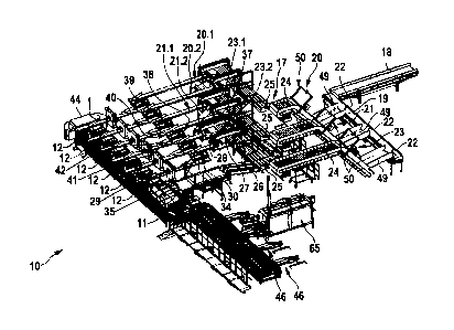
The invention deals with a fish supply system 10, configured and adapted for
automatedly supplying fish 100, in particular of the salmon species, with
defined
head/tail alignment and defined prone/supine alignment automatically to a fish
processing apparatus 65, comprising a speed conveyor 11, which is configured
and
adapted for transverse axially conveying the fish 100 with defined head/tail
alignment
and defined prone/supine alignment to the fish processing apparatus 65, as
well as at
least two feeding apparatuses 12 arranged above the speed conveyor 11, which
each
comprise at least one cascade conveyor 13 for transverse axially conveying the
fish
100, having at least two receptacles 15 separated from each other by two
controllable
flaps 14, wherein each cascade conveyor 13 has at least one clocking flap 16
for the
controlled output of fish 100 to the speed conveyor 11 at least in the last
receptacle 15
prior to the speed conveyor 11 in conveying direction.
This fish supply system 10 is characterised according to the invention in that
a supply
device 17 is allocated to the speed conveyor 11 with the feeding apparatuses
12, which
supply device comprises the following components, coming from the apparatus
for
bleeding the fish: a first central conveyor belt 18 for conveying the fish 100
from the
18558-CA English
Date Recue/Date Received 2022-12-19
- 14 -
apparatus for bleeding in the direction of the speed conveyor 11, wherein flow
scales
for determining the regulated mass throughput of fish 100 flowing from the
apparatus
for bleeding onto the first conveyor belt 18 is allocated to the first
conveyor belt 18, a
second central conveyor belt 19 following on from the first conveyor belt 18
for
conveying the fish 100 in the direction of the speed conveyor 11, wherein the
second
conveyor belt 19 is configured and adapted to be speed regulatable, at least
two
conveyor strands 20, 21, 23, which continuously connect the second conveyor
belt 19
with the feeding apparatuses 12 of the speed conveyor 11 for supplying the
fish 100,
wherein control flaps 22 for separating out the fish 100 from the second
conveyor belt
19 to the at least two conveyor strands 20, 21 are allocated to the second
conveyor
belt 19, and a control device 44 connected at least with the first conveyor
belt 18 and
the flow scales, the second conveyor belt 19 and the control flaps 22, the
conveyor
strands 20, 21 as well as the speed conveyor 11 and the feeding apparatuses 12
in a
control technical way for supplying the speed conveyor 11 with fish 100.
The features and further developments described in the following constitute
preferred
embodiments on their own or in combination with each other. It is specifically
pointed
out that features summarised in the claims and/or the description and/or the
drawing or
described in a common embodiment can also develop the fish supply system 10
described above further in a functionally independent way.
The first conveyor belt 18 is aligned at a substantially right angle to the
second
conveyor belt 19. The two conveyor belts 18, 19 can also be arranged at any
other
angle to each other, in particular also flush. The speed conveyor 11 is a
transverse
conveyor, which for conveying the fish 100 is configured transverse to their
head/tail
alignment. The orientation of the fish 100 with regard to their head/tail
alignment can be
any in principle, wherein the fish 100 are preferably orientated in such a way
that
conveyed behind the speed conveyor 11 they are with their tail first. The
embodiment
shown has a third conveyor strand 23 in addition to the two conveyor strands
20, 21.
The three, or also more conveyor strands 20, 21, 23 are all constructed
comparably,
which is why only one of the conveyor strands 20, 21, 23 is described in more
detail in
the following by way of example. The other conveyor strands 23, 21, 20 are
configured
comparably. A feeding apparatus 12E is allocated to ach conveyor strand 20,
21, 23.
Each feeding apparatus 12 comprises at least one cascade conveyor 13 with
several
receptacles 15 separated from each other by controllable flaps 14. With two
receptacles 15 at least one of the flaps 14 is a controllable storage flap
element. The
18558-CA English
Date Recue/Date Received 2022-12-19
- 15 -
last flap 14 before the speed conveyor 11 in conveying direction is the
controllably
moveable clocking flap 16.
For a continuous and gapless connection of the second conveyor belt 19 with
the
feeding apparatuses 12, each conveyor strand 20, 21, 23 comprises at least one
ascending conveyor 24 following on from the second conveyor belt 19 for
separating
and transverse axially conveying the fish 100, a slide 25 following on from
the
ascending conveyor 24 for untangling the fish 100, a first belt conveyor 26
following on
from the slide 25 for the longitudinal conveying of the fish 100, at least one
handling
apparatus 27 arranged above the first belt conveyor 26 which is configured and
adapted for taking the fish 100 off the first belt conveyor 26 and releasing
the fish 100
head first to at least one second belt conveyor 28, and the or any second belt
conveyor
28 following on from the first belt conveyor 26 for longitudinal axially
conveying the fish
100 head first, to which a deflector 29 for deflecting the fish 100 from the
second belt
conveyor 28 to a cascade conveyor 30 is allocated, the cascade conveyor 30
following
on from the second belt conveyor 28 for transverse axially conveying the fish
100,
which has at least two receptacles 32 separated from each other by
controllable flaps
31, wherein the cascade conveyor 30 has at least one clocking flap 33 in in
the last
receptacle 32 in conveying direction, a third belt conveyor 34 following on
from the
cascade conveyor 30 for longitudinal axially conveying the fish 100 head
first, a turning
station 35 allocated to the third belt conveyor 34 for carrying out a
correction of the
prone/supine alignment, and a handling apparatus 36 arranged above the third
belt
conveyor 34 for transverse axially conveying the fish 100 from the third belt
conveyor
34 to one of the feeding apparatuses 12. The ascending conveyor 24, the first
belt
conveyor 26, the or each handling apparatus 27, the second belt conveyor 28,
the
cascade conveyor 30 with the clocking flap 33, the third belt conveyor 34 and
the or
each handling apparatus 36 are preferably connected with the control device 44
in
order to be able to centrally collect and/or process and/or control the data
and/or
information of the components.
Two handling apparatuses 27, 37 are allocated to the first belt conveyor 26
one behind
the other in conveying direction in the illustrated embodiment in such a way
that parts
of the product stream formed by the fish 100 and lying on the first belt
conveyor 26 are
taken off by the first handling apparatus 27 and other parts of the product
stream are
taken off by the second handling apparatus 37. The product stream or each
conveyor
strand 20, 21, 23, respectively, are thus divided into two partial strands
20.1, 20.2;
18558-CA English
Date Recue/Date Received 2022-12-19
- 16 -
21.1, 21.2; 23.1, 23.2, so that each partial strand 20.1, 20.2; 21.1, 21.2;
23.1, 23.2
supplies one feeding apparatus 12. The individual components of each partial
strand
20.1, 20.2; 21.1, 21.2; 23.1, 23.2 are preferably identical in construction. A
second belt
conveyor 28, 38 is provided behind each handling apparatus 27, 37 for this
purpose,
which belt conveyor 28, 38 supplies a separate cascade conveyor 30, 40 via a
deflector 29, 39. The or each deflector 29, 39 can be a simple, locationally
fixed
deflector plate. The or each deflector 29, 39 can however optionally also be a
controlled deflector flap. The or each cascade conveyor 30, 40 following the
second
belt conveyor 28, 38 is preferably configured according to the cascade
conveyor 13 of
the feeding apparatus 12. Each cascade conveyor 30, 40 is followed by a third
belt
conveyor 34, 41 with its own turning station 35, 42 as well as with its own
handling
apparatus 36, 43, which are configured for releasing the fish 100 to separate
feeding
apparatuses 12.
The control device 44, with which all components of the fish supply system 10
are
preferably connected, comprises a program component that is configured and
adapted
for adjusting the capacity of the conveyor strands 20, 21, 23 to the capacity
of the
speed conveyor 11. All information supplied to the control devices 44, in
particular in
the form of control signals, which amongst other things include information
about the
number of fish supplied, the mass throughput as well as the capacities of the
speed
conveyor 11 on the one hand, and all conveyor strands 20, 21, 23 on the other
hand,
are processed by means of the control device 44 and related to each other
and/or
brought in connection with each other in order to control the fish supply
system 10 with
regard to a maximum and gapless filling of the speed conveyor 11.
The speed conveyor 11 as a transverse conveyor is a circumferentially driven
endless
conveyor and comprises troughs 45 for the individual reception of fish,
wherein each
trough 45 is configured and adapted for forwarding the fish 100 to a
longitudinal
conveyor 46 lying below the troughs 45, wherein the longitudinal conveyor 46
is
configured and adapted for longitudinal axially conveying the fish 100, tail
first. The
troughs 45 are equipped with fish 100 in an upper run 47 of the speed conveyor
11.
The troughs 45 return empty in a lower run 48. The longitudinal conveyors 46
are
preferably placed between the upper run 47 and the lower run 48 in order to
receive
the fish 100 sliding out of the troughs 45. For releasing the fish 100 to the
longitudinal
conveyor 46 the troughs 45 have a moveable floor such that the floor or parts
thereof
18558-CA English
Date Recue/Date Received 2022-12-19
- 17 -
can be controlled flap-like from a closed position into a release position and
back
again.
Scales (not explicitly illustrated) for determining the actual mass of the
fish 100 to be
conveyed are arranged before the ascending conveyor 24 between the second
conveyor belt 19 and the ascending conveyor 24 of each conveyor strand 20, 21,
23 in
the illustrated embodiment. The scales are preferably integrated into a slide
49, which
ensures a sliding transfer of the fish 100 from the second conveyor belt 19 to
the
ascending conveyor 24. Each ascending conveyor 24 is configured as a
circumferentially driven trough conveyor and a detection means for detecting
the
occupation of the troughs of the ascending conveyor is allocated to the
ascending
conveyor 24 of each conveyor strand 20, 21, 23. The detection means 50 can be
a
simple camera arranged above an upper run of the trough conveyor at a portal.
The
number of cameras or any other suitable detection means 50 as well as their
positioning can of course vary. The or each detection means 50 is preferably
connected with the control device 44 in order to be able to centrally collect
and process
the data and/or information of the detection means 50. The ascending conveyor
24
itself can also be in operative connection with the control device 44 in order
to be able
to control the ascending conveyor 24. The or each ascending conveyor 24
comprises
not only the upwards running upper run for the separate conveying of the fish
100 lying
in the troughs, but also a downwards running lower run for returning the empty
troughs.
At the upper end of the ascending conveyor 24 the same is configured and
adapted to
issue the fish 100 in the deflection region 51 from upper run to lower run.
Each ascending conveyor 24 is allocated a housing 52 in the deflection region
51 from
upper run to lower run for this, which housing 52 is configured and adapted
for guiding
and holding the fish 100 in the troughs, wherein the housing 52 has at least
one
controlled flap 53 for the overhead release of the fish 100 from the ascending
conveyor
24 on the side facing the upper run above the conveyor means downstream from
the
ascending conveyor 24. To put it simply the deflection region describes a U-
turn so that
a horizontally aligned output region 54 is formed in such a way that several
troughs of
the ascending conveyor 24 lie above the following conveyor means. An output of
fish
100 that is staggered in the direction of width and/or length of the following
conveyor
means is thus guaranteed. The or each flap 53 is preferably connected with the
control
device 44 in order to be able to control the flap 53. The following conveyor
means is a
circumferentially driven belt conveyor 55 in the embodiment shown, by means of
which
18558-CA English
Date Recue/Date Received 2022-12-19
- 18 -
the fish 100 can be conveyed to the slide 25. The slide 25 has several paths,
gulleys or
suchlike distributed across its width in such a way that the fish 100 can be
conveyed in
several tracks next to each other in the direction of the first belt conveyor
26. In the
embodiment shown, the slide 25 is exemplarily followed by a belt conveyor 66
with
guide plates 67 arranged in a fan shape, by means of which the fish 100 are
guided
onto the first belt conveyor 26, distributed across its width. Both belt
conveyors 55, 56
are preferably connected with the control device 44 in order to be able to
control the
belt conveyors 55, 56.
At least one detection means 56 for detecting the position of the fish 100 on
the belt
conveyor 26 and for detecting the orientation of the fish 100 on the belt
conveyor are
allocated to the first belt conveyor 26 of each conveyor strand 20, 21, 23.
The detection
means 56 can be a simple camera, which is arranged at a portal above the first
belt
conveyor 26. The number of cameras or any other suitable detection means 56 as
well
as their positioning can of course vary. The or each detection means 56 is
preferably
connected with the control device 44 much like the first belt conveyor 26 in
order to be
able to centrally collect and process the data and/or information of the
detection means
50 and control the first belt conveyor 26.
The or each handling apparatuses 27, 37 allocated to the first belt conveyor
26 are
configured and adapted for establishing an operative connection with the fish
by being
positioned on the same from above as well as for aligning and pulling the
sliding fish
100 from the first belt conveyor 26 to the or each second belt conveyor 28,
38. Each
handling apparatus 27, 37 has a linear guide 57, on which a displaceable
cartridge 58
is arranged. The cartridge 58 is displaceable along the linear guide 57
transverse to the
conveying direction of the first belt conveyor 26. The linear guide 57, or
preferably the
cartridge 58, is additionally configured to also be moveable vertical to the
first belt
conveyor 26. A gripper head 59 is arranged on the cartridge 58 as a gripper
means,
which is rotatably mounted on the cartridge 58. In the embodiment shown the
gripper
head 59 comprises several, preferably four holding paddles, configured and
adapted
for abutting the fish 100 lying on one side. The or each holding apparatus 27,
37 is
preferably connected with the control device 44 in order to be able to control
the
handling apparatus 27, 37. The fish 100 can be pulled from the first belt
conveyor 26
directly onto the second belt conveyor 28, 38 by means of the gripper head 59
and
aligned head first in this way. In the specific embodiment the first belt
conveyor 26 and
the second belt conveyor 28, 38 are connected with each other by a slide 60.
The
18558-CA English
Date Recue/Date Received 2022-12-19
- 19 -
defined head/tail alignment of the fish 100 therefore takes place in the
transition region
between the first belt conveyor 26 and the second belt conveyors 28, 38. Each
second
belt conveyor 28, 38 is preferably connected with the control device 44 in
order to be
able to control the second belt conveyor 28, 38.
Apart from the turning station 35, 42 at least one detection device 61, 62 is
allocated to
the third belt conveyor 34, 41 behind the turning station 35, 42 and before
the feeding
apparatus 12, which detection device is configured and adapted for assessing
different
quality criteria. The detection device 61, 62 is configured as a camera
station with four
cameras. The number of cameras or any other suitable detection device 61, 62
as well
as their positioning can of course vary. The or each detection device 61, 62
is
connected with the control device 44 in order to be able to centrally collect
and process
the data and/or information of the detection device 61, 62. The third belt
conveyor 34,
41 can be configured continuously up to the feeding apparatus 12. In the
embodiment
shown the third belt conveyor 34, 41 is divided in such a way that a fourth
belt
conveyor 63, 64 is arranged flush behind the third belt conveyor 34, 41 in
conveying
direction, wherein the detection device 61, 62 is arranged in the transition
from the third
belt conveyor 34, 41 to the fourth belt conveyor 63, 64 and the handling
device 36, 43
for transverse axially conveying the fish 100 to the feeding apparatus 12 is
arranged on
the fourth belt conveyor 63, 64. The or each fourth belt conveyor 63, 64 is
preferably
connected with the control device 44 in order to be able to control the fourth
belt
conveyor 63, 64.
The fish supply system 10 can also be divided across more than three conveyor
strands 20, 21, 23 and/or each conveyor strand 20, 21, 23 can be divided into
more
than two partial strands 20.1, 20.2; 21.1, 21.2; 23.1, 23.2.
The method will be explained in more detail with reference to the drawing in
the
following. The method serves for supplying fish 100, in particular of the
salmon
species, with defined head/tail alignment and defined prone/supine alignment
to at
least one fish processing apparatus 65 and is correspondingly suited. The
method
comprises the steps: aligning the fish 100 in the defined head/tail alignment
and the
defined prone/supine alignment, positioning the aligned fish 100 in a feeding
apparatus
12 upstream of the speed conveyor 11 for transverse axially conveying the fish
100,
wherein the fish 100 are conveyed from a receptacle 15 of a cascade conveyor
13 to
the next receptacle 15 of the cascade conveyor 13 in the feeding apparatuses
12 until
18558-CA English
Date Recue/Date Received 2022-12-19
- 20 -
they lie in conveying direction in the last receptacle 15 at a clocking flap
16, by means
of which the fish 100 are supplied to the speed conveyor 11 in a controlled
way, and
transverse axially conveying the fish 100 supplied to the speed conveyor 11 in
the
direction of the or each fish processing apparatus 65. The speed conveyor 11
preferably supplies four fish processing apparatuses 65.
This method is characterised according to the invention in that the fish 100
is conveyed
by means of a supply device 17 from a device for bleeding the fish 100 to a
feeding
apparatus 12 of the speed conveyor 11, wherein the fish 100 are continuously
automatically conveyed starting from the device for bleeding to the speed
conveyor 11,
and the regulated mass throughput of fish 100 is determined, and the fish 100
are
conveyed in a speed regulated way and distributed onto several conveyor
strands 20,
21, 23 in a controlled way, wherein the supply device 17 is controlled at the
speed
conveyor 11 depending on the capacity required.
The fish 100 are stunned and then killed. The fish 100 are counted during
this. The
counted fish 100 are then supplied to the device for bleeding, for example a
spiral tank.
The fish 100 are then guided directly onto a first conveyor belt 18, which is
part of the
supply device 17, from the spiral tank unsorted and as a batch. The fish 100
are then
conveyed from the device for bleeding the fish 100 to one or more ascending
conveyors 24 by means of the first conveyor belt 18 and the second conveyor
belt 19.
The mass throughput of the fish 100 is determined along or on the first
conveyor belt
18. The conveying speed, in particular of the second conveyor belt 19, is
regulated in
order to distribute the required mass of fish 100 to individual conveyor
strands 20, 21,
23. Control flaps 22 on the second conveyor belt 19 are controlled for this
purpose.
The fish 100 are, initially individually separated along each conveyor strand
20, 21, 23,
namely for example by means of the ascending conveyor 24, then untangled,
namely
for example by means of a slide 25, then aligned head first with regard to
head/tail
alignment, namely for example by means of a handling apparatus 27, 37, then
aligned
with regard to prone/supine alignment, namely for example by means of a
turning
station 35, 42, and subsequently supplied to the feeding apparatuses 12. The
fish 100
are continuously supplied by several conveyor means for this, which guarantee
continuous conveying from the second conveyor belt 19 to the feeding
apparatuses 12.
Starting with the second conveyor belt 19, in the embodiment shown the
ascending
conveyor 24, the slide 25, a first belt conveyor 26, a second belt conveyor
28, 38, a
18558-CA English
Date Recue/Date Received 2022-12-19
- 21 -
cascade conveyor 30, 40 and a third belt conveyor 34, 41 form a continuous
conveying
path,. Each conveyor strand 20, 21, 23 in fact divides into two partial
strands 20.1,
20.2; 21.1, 21.2; 23.1, 23.2 behind the first conveyor belt 26. The actual
mass of fish
100 along each conveyor strand 20, 21, 23 is determined, for example by means
of
scales, before the fish 100 are taken over by the ascending conveyor 24.
According to the arrangement of the conveyor means the fish 100 are conveyed
first
transverse axially, then longitudinal axially along each conveyor strand 20,
21, 23, then
turned around an axis of rotation, which is aligned vertical to the
longitudinal alignment
of the fish 100 and vertical to the plane of transportation, then conveyed
initially
longitudinal axially again, then transverse axially, and then longitudinal
axially again,
before they are transverse axially conveyed into the feeding apparatus 12.
Whilst
conveying the fish 100 along the conveying path a first detection for
detecting the
occupation of each conveyor strand 20, 21, 23 takes place during the
transverse
conveying of the fish 100 in an ascending conveyor 24 along each conveyor
strand 20,
21, 23. It is detected, for example with a camera, whether troughs of the
ascending
conveyor 24 are unoccupied or are occupied doubly or multiple times. This
information
is forwarded to the control device 44. A second detection for detecting the
position of
the fish 100 and the head/tail alignment is carried out on each conveyor
strand 20, 21,
23 whilst further carrying the fish 100 along the conveying path along each
conveyor
strand 20, 21, 23 during the longitudinal conveying of the fish 100 on the
first belt
conveyor 26. The fish 100 lie on the first belt conveyor 26 with their
longitudinal
expansion in conveying direction at a distance from each other on several
paths next to
each other. The position of every fish 100 on the belt conveyor 26 is detected
on the
one hand, for example with a camera. On the other hand, its head/tail
alignment is
detected. This information is forwarded to the control device 44, which then
controls the
handling apparatuses 27, 37 accordingly in such a way that the fish 100 is
moved head
first onto the second belt conveyor 28, 38.
Alignment in the correct and final head/tail alignment takes place when a
force is
applied from above to the fish 100 lying on the first belt conveyor 26 and the
fish are
then pulled from the first belt conveyor 26 onto a second belt conveyor 28, 38
by
means of the handling apparatus 27, 37, wherein the fish 100 are then aligned
head
first. Following the head/tail alignment the fish 100 are conveyed to the
clocking flap
33, receptacle 32 by receptacle 32, via the cascade conveyor 30, 40 and
transferred to
the second belt conveyor 28, 38 in a controlled way. The fish 100 are then
also aligned
18558-CA English
Date Recue/Date Received 2022-12-19
- 22 -
with regard to the prone/supine alignment on the second belt conveyor 28, 38
following
the head/tail alignment. For this the fish 100 are forced through the turning
station 35,
42. Once they leave the turning station 35, 42 the fish 100 are conveyed
through the
third belt conveyor 34, 41 or from the third belt conveyor 34, 41 and a fourth
belt
conveyor 63, 64 to the feeding apparatuses 12. On the way to the latter the
fish 100
pass a detection device 61, 62 for assessing different quality criteria during
the
longitudinal conveying of the fish 100. This information is forwarded to the
control
device 44, by means of which the handling apparatus 36, 43 is controlled in
such a way
that the fish 100, which preferably fulfil the quality criteria stored in the
control device
44, are pulled off the third belt conveyor 34, 41 and conveyed into the
receptacles 15 of
the cascade conveyor 13 of the feeding apparatus 12, whilst fish 100 that do
not
comply with the quality criteria pass the handling device 36, 43 and are
separated out.
The method is preferably carried out with a fish supply system 10 according to
one or
several of the claims 1 to 14.
18558-CA English
Date Recue/Date Received 2022-12-19