Note: Descriptions are shown in the official language in which they were submitted.
REHEAT SCHEDULING FOR WATER HEATERS
TECHNICAL FIELD
[0001] The present disclosure relates to water heaters, and more particularly
to scheduling of
reheating cycles for water heaters.
BACKGROUND
[0002] There have been many attempts to balance the load on electrical
utilities, and to
distribute demand either more evenly throughout the day or into periods where
the electricity
has lower costs. One particular target of these efforts has been water
heaters, given their
significant electrical demands.
[0003] U.S. Patent No. 6,208,806 to Newton Langford describes a domestic water
heater that
includes a water meter and a timer. A programmable means stores water usage
and heating
data to determine the time period required for heating the water in the tank,
and also stores
power load curve data from the power utility and matches the required heating
time to an
appropriate portion of a low in the power load curve. By pre-allocating the
tanks into groups,
a power utility can reallocate the water heater power load into low cost
periods of the power
load curve.
SUMMARY
[0004] In one aspect, a method for reheating a tank-style water heater
comprises obtaining
full reheating duration data from a volumetric tank flow for the tank,
communicating the full
reheating duration data to a power scheduler, and, responsive to a timed full
reheat signal
from the power scheduler, initiating a full reheating cycle for the tank to
reheat the water in
the tank to the setpoint temperature, wherein the timed full reheat signal
times initiation of the
full reheating cycle to complete the full reheating cycle prior to a
predetermined time
according to an estimated full reheating time.
[0005] In one embodiment, the full reheating duration data may be a duration
required to fully
reheat the tank to the setpoint temperature calculated from the volumetric
tank flow. In
another embodiment, the full reheating duration data may comprise the
volumetric tank flow,
1
Date Recue/Date Received 2022-09-28
and the power scheduler may calculate a duration required to fully reheat the
tank to the
setpoint temperature from the volumetric tank flow.
[0006] In some embodiments, the volumetric tank flow may be one of a
volumetric inflow
into the tank, a volumetric outflow from the tank, and a combination of the
volumetric inflow
into the tank and the volumetric outflow from the tank.
[0007] In some embodiments, the power scheduler may be one of a power utility
and a third
party power scheduler.
[0008] In some embodiments, the method may further comprise, responsive to the
volumetric
tank flow exceeding a first reheat threshold, initiating a first interim
reheating cycle for the
tank, after the first interim reheating cycle, curtailing heating of the tank,
obtaining first
updated full reheating duration data according to the first interim reheating
cycle and the
volumetric tank flow, and communicating the first updated full reheating
duration data to the
power scheduler. In one such embodiment, the first updated full reheating
duration data may
be a duration required to fully reheat the tank to the setpoint temperature
calculated from the
volumetric tank flow and the first interim reheating cycle. In another such
embodiment, the
first updated full reheating duration data may comprise the volumetric tank
flow and first
interim reheating cycle data, and the power scheduler may calculate a duration
required to
fully reheat the tank to the setpoint temperature from the volumetric tank
flow and the first
interim reheating cycle data.
[0009] In some embodiments, the predetermined time may be based on load
balancing by the
power scheduler.
[0010] In some embodiments, the first interim heating cycle may be initiated
immediately
upon exceeding the first reheat threshold. In other embodiments, the first
interim heating
cycle may be scheduled for a time after exceeding the first reheat threshold.
[0011] In some embodiments, the method may further comprise, responsive to the
volumetric
tank flow exceeding a second reheat threshold that is greater than the first
reheat threshold,
initiating a second interim reheating cycle for the tank, after the second
interim reheating
2
Date Recue/Date Received 2022-09-28
cycle, again curtailing heating of the tank, obtaining second updated full
reheating duration
data according to the second interim reheating cycle and the volumetric tank
flow, and
communicating the second updated full reheating duration data to the power
scheduler.
[0012] In some embodiments, the second updated full reheating duration data
may be a
duration required to fully reheat the tank to the setpoint temperature
calculated from the
volumetric tank flow, the first interim reheating cycle and the second interim
reheating cycle.
In other embodiments, the second updated full reheating duration data may
comprise the
volumetric tank flow, the first interim reheating cycle data and the second
interim reheating
cycle data, and the power scheduler my calculate a duration required to fully
reheat the tank to
the setpoint temperature from the volumetric tank flow, the first interim
reheating cycle data
and the second interim reheating cycle data.
[0013] In some embodiments, communicating the full reheating duration data to
the power
scheduler may occur daily.
[0014] In another aspect, a controller for controlling reheating of a tank-
style water heater is
provided. The controller is adapted to selectively activate and deactivate at
least one water
heater heating element and cause the at least one water heater heating element
to perform
heating until deactivated by the controller or terminated by at least one
respective water heater
limit switch. The controller is adapted to monitor volumetric tank flow for
the water heater
and to communicate with a power scheduler. The controller executes program
logic for
obtaining full reheating duration data from a volumetric tank flow for the
tank,
communicating the full reheating duration data to the power scheduler, and
responsive to a
timed full reheat signal from the power scheduler, initiating a full reheating
cycle for the tank
to reheat the water in the tank to the setpoint temperature. The timed full
reheat signal times
initiation of the full reheating cycle to complete the full reheating cycle
prior to a
predetermined time according to an estimated full reheating time.
[0015] In one embodiment, the full reheating duration data may be a duration
required to fully
reheat the tank to the setpoint temperature calculated from the volumetric
tank flow. In
another embodiment, the full reheating duration data may comprise the
volumetric tank flow,
3
Date Recue/Date Received 2022-09-28
and the power scheduler may calculate a duration required to fully reheat the
tank to the
setpoint temperature from the volumetric tank flow.
[0016] In some embodiments, the volumetric tank flow may be one of a
volumetric inflow
into the tank, a volumetric outflow from the tank and a combination of the
volumetric inflow
into the tank and the volumetric outflow from the tank.
[0017] In some embodiments, the power scheduler may be one of a power utility
and a third
party power scheduler.
[0018] In some embodiments, the controller may further execute program logic
for,
responsive to the volumetric tank flow exceeding a first reheat threshold,
initiating a first
interim reheating cycle for the tank, after the first interim reheating cycle,
curtailing heating
of the tank, obtaining first updated full reheating duration data according to
the first interim
reheating cycle and the volumetric tank flow, and communicating the first
updated full
reheating duration data to the power scheduler.
[0019] In some embodiments, the first updated full reheating duration data may
be a duration
required to fully reheat the tank to the setpoint temperature calculated from
the volumetric
tank flow and the first interim reheating cycle. In other embodiments, the
first updated full
reheating duration data may comprise the volumetric tank flow and first
interim reheating
cycle data, and the power scheduler may calculate a duration required to fully
reheat the tank
to the setpoint temperature from the volumetric tank flow and the first
interim reheating cycle
data.
[0020] In some embodiments, the predetermined time may be based on load
balancing by the
power scheduler.
[0021] In some embodiments, the first interim heating cycle may be initiated
immediately
upon exceeding the first reheat threshold. In other embodiments, the first
interim heating
cycle may be scheduled for a time after exceeding the first reheat threshold.
4
Date Recue/Date Received 2022-09-28
[0022] In some embodiments, the controller may further execute program logic
for,
responsive to the volumetric tank flow exceeding a second reheat threshold
that is greater than
the first reheat threshold, initiating a second interim reheating cycle for
the tank, after the
second interim reheating cycle, again curtailing heating of the tank,
obtaining second updated
full reheating duration data according to the second interim reheating cycle
and the volumetric
tank flow, and communicating the second updated full reheating duration data
to the power
scheduler.
[0023] In some embodiments, the second updated full reheating duration data
may be a
duration required to fully reheat the tank to the setpoint temperature
calculated from the
volumetric tank flow, the first interim reheating cycle and the second interim
reheating cycle.
[0024] In some embodiments, the second updated full reheating duration data
may comprise
the volumetric tank flow, the first interim reheating cycle data and second
interim reheating
cycle data, and the power scheduler may calculate a duration required to fully
reheat the tank
to the setpoint temperature from the volumetric tank flow, the first interim
reheating cycle
data and the second interim reheating cycle data.
[0025] In some embodiments, the controller may be configured to communicate
the full
reheating duration data to the power scheduler daily.
[0026] In another aspect, a method for controlling reheating of a tank-style
water heater
having at least an upper heating element and a lower heating element comprises
monitoring
the water heater for presence or absence of an upper heating element
activation signal
indicating activation of the upper heating element, responsive to detecting
the presence of the
upper heating element activation signal, permitting supply of electrical power
to the water
heater, and responsive to detecting the absence of the upper heating element
activation signal,
denying supply of electrical power to the water heater outside of a scheduled
time.
[0027] In some embodiments, the water heater has at least one intermediate
heating element
disposed between the upper heating element and the lower heating element.
5
Date Recue/Date Received 2022-09-28
[0028] In another aspect, a controller for controlling reheating of a tank-
style water heater
having at least an upper heating element and a lower heating element is
provided. The
controller is adapted to selectively permit and deny supply of electrical
power to the water
heater and is adapted to detect an upper heating element activation signal
indicating activation
of the upper heating element. The controller executes program logic for
monitoring the water
heater for presence or absence of the upper heating element activation signal,
responsive to
detecting the presence of the upper heating element activation signal,
permitting supply of
electrical power to the water heater and, responsive to detecting the absence
of the upper
heating element activation signal, denying supply of electrical power to the
water heater
outside of a scheduled time.
[0029] In a further aspect, a method for reheating a tank-style water heater
having an upper
heating element and a lower heating element comprises monitoring a volumetric
tank flow for
the tank, responsive to the volumetric tank flow exceeding a first reheat
threshold, testing the
water heater for presence or absence of an upper heating element activation
signal indicating
activation of the upper heating element, responsive to detecting the presence
of the upper
heating element activation signal, initiating a first interim reheating cycle
for the tank and,
after the first interim reheating cycle, curtailing heating of the tank, and
responsive to
detecting the absence of the upper heating element activation signal, delaying
the first interim
reheating cycle for the tank.
[0030] In some embodiments, initiating the first interim reheating cycle for
the tank
comprises permitting supply of electrical power to the water heater and
delaying the first
interim reheating cycle for the tank comprises denying supply of electrical
power to the water
heater outside of a scheduled time.
[0031] In yet a further aspect, a controller for controlling reheating of a
tank-style water
heater having at least an upper heating element and a lower heating element is
provided. The
controller is adapted to control activation and deactivation of the upper
heating element and
the lower heating element and cause the upper heating element and the lower
heating element
to perform heating until deactivated by the controller or terminated by a
respective limit
switch. The controller is also adapted to monitor volumetric tank flow for the
water heater
6
Date Recue/Date Received 2022-09-28
and to detect an upper heating element activation signal indicating activation
of the upper
heating element. The controller executes program logic for monitoring the
volumetric tank
flow for the tank, responsive to the volumetric tank flow exceeding a first
reheat threshold,
testing the water heater for presence or absence of the upper heating element
activation signal
indicating activation of the upper heating element, responsive to detecting
the presence of the
upper heating element activation signal, initiating a first interim reheating
cycle for the tank
and, after the first interim reheating cycle, curtailing heating of the tank
and, responsive to
detecting the absence of the upper heating element activation signal, delaying
the first interim
reheating cycle for the tank.
[0032] In some embodiments, initiating the first interim reheating cycle for
the tank
comprises permitting supply of electrical power to the water heater and
delaying the first
interim reheating cycle for the tank comprises denying supply of electrical
power to the water
heater outside of a scheduled time.
[0033] In yet a further aspect, a method for reheating a tank-style water
heater having an
upper heating element and a lower heating element, comprises obtaining full
reheating
duration data from a volumetric tank flow for the tank communicating the full
reheating
duration data to a power scheduler and, responsive to a timed full reheat
signal from the
power scheduler, initiating a full reheating cycle for the tank to reheat the
water in the tank to
a setpoint temperature. The timed full reheat signal times initiation of the
full reheating cycle
to complete the full reheating cycle prior to a predetermined time according
to an estimated
full reheating time. The method further comprises, responsive to the
volumetric tank flow
exceeding a first reheat threshold where an upper heating element activation
signal indicating
activation of the upper heating element is present, initiating a first interim
reheating cycle for
the tank, after the first interim reheating cycle, curtailing heating of the
tank, obtaining first
updated full reheating duration data according to the first interim reheating
cycle and the
volumetric tank flow, and communicating the first updated full reheating
duration data to the
power scheduler.
[0034] In another aspect, a controller for controlling reheating of a tank-
style water heater
having at least an upper heating element and a lower heating element is
provided. The
7
Date Recue/Date Received 2022-09-28
controller is adapted to control activation and deactivation of the upper
heating element and
the lower heating element and cause the upper heating element and the lower
heating element
to perform heating until deactivated by the controller or terminated by a
respective limit
switch. The controller is adapted to monitor volumetric tank flow for the
water heater, to
detect an upper heating element activation signal indicating activation of the
upper heating
element, and to communicate with a power scheduler. The controller executes
program logic
for obtaining full reheating duration data from the volumetric tank flow for
the tank,
communicating the full reheating duration data to the power scheduler and,
responsive to a
timed full reheat signal from the power scheduler, initiating a full reheating
cycle for the tank
to reheat the water in the tank to a setpoint temperature. The timed full
reheat signal times
initiation of the full reheating cycle to complete the full reheating cycle
prior to a
predetermined time according to an estimated full reheating time. The
controller executes
further program logic for, responsive to the volumetric tank flow exceeding a
first reheat
threshold where the upper heating element activation signal is present,
initiate a first interim
reheating cycle for the tank, after the first interim reheating cycle,
curtailing heating of the
tank, obtaining first updated full reheating duration data according to the
first interim
reheating cycle and the volumetric tank flow and communicating the first
updated full
reheating duration data to the power scheduler.
[0035] In a still further aspect, a method for reheating a tank-style water
heater having an
upper heating element and a lower heating element comprises obtaining full
reheating
duration data from a volumetric tank flow for the tank, communicating the full
reheating
duration data to a power scheduler and, responsive to a timed full reheat
signal from the
power scheduler, initiating a full reheating cycle for the tank to reheat the
water in the tank to
a setpoint temperature. The timed full reheat signal times initiation of the
full reheating cycle
to complete the full reheating cycle prior to a predetermined time according
to an estimated
full reheating time. The method further comprises, responsive to determining
an upper
heating element activation signal indicating activation of the upper heating
element is present,
initiating a first interim reheating cycle for the tank, after the first
interim reheating cycle,
curtailing heating of the tank, obtaining first updated full reheating
duration data according to
8
Date Recue/Date Received 2022-09-28
the first interim reheating cycle and the volumetric tank flow and
communicating the first
updated full reheating duration data to the power scheduler.
[0036] In still yet a further aspect, a controller for controlling reheating
of a tank-style water
heater having at least an upper heating element and a lower heating element is
provided. The
controller is adapted to control activation and deactivation of the upper
heating element and
the lower heating element and cause the upper heating element and the lower
heating element
to perform heating until deactivated by the controller or terminated by a
respective limit
switch. The controller is further is adapted to monitor volumetric tank flow
for the water
heater, to detect an upper heating element activation signal indicating
activation of the upper
heating element, and to communicate with a power scheduler. The controller
executes
program logic for obtaining full reheating duration data from a volumetric
tank flow for the
tank, communicating the full reheating duration data to a power scheduler and,
responsive to a
timed full reheat signal from the power scheduler, initiating a full reheating
cycle for the tank
to reheat the water in the tank to a setpoint temperature. The timed full
reheat signal times
initiation of the full reheating cycle to complete the full reheating cycle
prior to a
predetermined time according to an estimated full reheating time. The
controller executes
further program logic for, responsive to determining the upper heating element
activation
signal is present, initiating a first interim reheating cycle for the tank,
after the first interim
reheating cycle, curtailing heating of the tank, obtaining first updated full
reheating duration
data according to the first interim reheating cycle and the volumetric tank
flow and
communicating the first updated full reheating duration data to the power
scheduler.
[0037] In implementations of the above-described embodiments, the upper
heating element
activation signal is a current in a circuit of the upper heating element when
electrical power is
supplied to the water heater. In other implementations of the above-described
embodiments,
the upper heating element activation signal is an electrical characteristic of
the water heater
when electrical power is supplied to the water heater. The electrical
characteristic may be a
current at an electrical input of the water heater or a resistance at an
electrical input of the
water heater. In some implementations of the above-described embodiments, the
upper
heating element activation signal is a sensor signal.
9
Date Recue/Date Received 2022-09-28
[0038] In another aspect, a method for controlling reheating of a tank-style
water heater
having an upper heating element and a lower heating element, comprises
identifying whether
the upper heating element, the lower heating element, or neither of the upper
heating element
and the lower heating element is energized when electrical power is supplied
to the water
heater, and determining whether to continue supply of electrical power to the
water heater
based on which of the upper heating element, the lower heating element or
neither of the
upper heating element and the lower heating element is energized when
electrical power is
supplied to the water heater.
[0039] In a further aspect, a controller for controlling reheating of a tank-
style water heater
having at least an upper heating element and a lower heating element is
provided. The
controller is adapted to selectively permit and deny supply of electrical
power to the water
heater, and the controller executes program logic for identifying whether the
upper heating
element, the lower heating element, or neither of the upper heating element
and the lower
heating element is energized when electrical power is supplied to the water
heater, and
determining whether to continue supply of electrical power to the water heater
based on
which of the upper heating element, the lower heating element or neither of
the upper heating
element and the lower heating element is energized when electrical power is
supplied to the
water heater.
[0040] In yet another aspect, a method for controlling reheating of a tank-
style water heater
having an upper heating element and a lower heating element, comprises
identifying whether
the upper heating element will be energized when electrical power is supplied
to the water
heater, and supplying the electrical power to the water heater only when the
upper heating
element will be energized thereby.
[0041] In still yet a further aspect, a controller for controlling reheating
of a tank-style water
heater having at least an upper heating element and a lower heating element is
adapted to
selectively permit and deny supply of electrical power to the water heater and
the controller
executes program logic for identifying whether the upper heating element will
be energized
when electrical power is supplied to the water heater and supplying the
electrical power to the
water heater only when the upper heating element will be energized thereby.
Date Recue/Date Received 2022-09-28
BRIEF DESCRIPTION OF THE DRAWINGS
[0042] These and other features of the invention will become more apparent
from the
following description in which reference is made to the appended drawings
wherein:
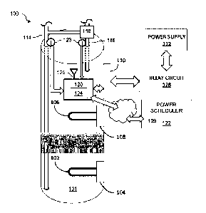
FIGURE 1 is a block diagram showing an illustrative tank-style electric water
heater with a
controller according to an aspect of the present disclosure;
FIGURE 2 is a flowchart showing a first illustrative method for reheating
water in a tank-style
electric water heater;
FIGURE 3 is a plot showing a function and a best fit line relating volume of
water
consumption (since tank was last fully reheated and then power curtailed) to
load, represented
both in kW hours and by reheating time;
FIGURE 4 is a flow chart showing a second illustrative method for reheating
water in a tank-
style electric water heater;
FIGURE 4A is a flow chart showing a third illustrative method for reheating
water in a tank-
style electric water heater
FIGURE 5 is a flow chart showing a fourth illustrative method for reheating
water in a tank-
style electric water heater;
FIGURE 6 is a flowchart showing a fifth illustrative method for reheating
water in a tank-
style electric water heater; and
FIGURE 7 is a flowchart showing a sixth illustrative method for reheating
water in a tank-
style electric water heater;
DETAILED DESCRIPTION
[0043] Reference is now made to Figure 1, which shows an illustrative tank-
style electric
water heater 100 coupled to a controller 120 according to an aspect of the
present disclosure.
The water heater 100 comprises a tank 101 and includes a lower heating element
102, a lower
thermostatically controlled temperature limit switch 104, an upper heating
element 106, an
11
Date Recue/Date Received 2022-09-28
upper thermostatically controlled temperature limit switch 108, and an
electrical junction 110.
For clarity, the terms "lower" and "upper" refer to the physical position of
the heating
elements and temperature limit switches when the water heater 100 is upright,
and not to
temperature values. The electrical junction 110 is coupled in electrical
communication with
an electrical power supply 112, for example 220V AC, via a relay circuit 128.
Electrical
power to the lower heating element 102 and the upper heating element 106 from
the junction
110 is governed by the temperature limit switches 104, 108. The lower
temperature limit
switch 104 and the upper temperature limit switch 108 are typically robust
thermo-mechanical
thermostats, such as adjustable mechanical "snap-disk" thermostats that
physically open an
electrical circuit when a set temperature is reached, although other types of
thermostatically
controlled temperature limit switches may be used. Other components of the
water heater 100
are known to those of skill in the art, and are omitted for simplicity of
illustration.
[0044] The water heater 100 has a water inlet 114 for receiving cooler water
into the tank
101, for example from a municipal water supply, a water outlet 116 for
releasing heated water
from the tank 101, and may include a mixing valve 118 for mixing the cooler
water with the
heated water to achieve a more comfortable temperature.
[0045] In one typical embodiment, when both the lower temperature limit switch
104 and the
upper temperature limit switch 108 are open, indicating the temperature has
risen above a
predetermined level (the setpoint temperature), the open temperature limit
switches 104, 108
will interrupt the electrical power to the lower heating element 102 and the
upper heating
element 106, respectively, to prevent overheating. Where a mixing valve (e.g.
mixing valve
118) is present to prevent scalding, the predetermined level may be set to 60
C or higher to
comply with World Health Organization recommendations for Legionella control.
Other
types of electric water heater may have a single heating element and a single
temperature limit
switch, or more than two heating elements and temperature limit switches (e.g.
three). For
example, a water heater may have at least one intermediate heating element
disposed between
the upper heating element and the lower heating element. In any case, when all
of the
temperature limit switch(es) are open, indicating that the setpoint
temperature has been
reached, the temperature limit switch(es) will interrupt the electrical power
to the heating
12
Date Recue/Date Received 2022-09-28
element(s) and the water heater will cease to draw current. Accordingly,
unless interrupted by
the controller 120, where the setpoint temperature is 60 C or higher, the
water heater will
only cease to draw current when the temperature has reached a level sufficient
to comply with
WHO recommendations for Legionella control. Optionally, a safety override
circuit as
described in Canadian Patent Application No. 3,129,944 filed September 3, 2021
may be used
for Legionella control during load shifting.
[0046] The controller 120 monitors volumetric tank flow, and communicates with
a power
scheduler 122, which may be a power utility or a third party power scheduler,
which may in
turn cooperate with the power utility. In the illustrated embodiment, the
controller 120 is
coupled to flow meters 123 on both the water inlet 114 and the water outlet
116, although in
other embodiments the controller may be coupled only to a flow meter on the
water inlet or
only to a flow meter on the water outlet. Thus, the volumetric tank flow may
be the
volumetric inflow into the tank (e.g. through water inlet 114), the volumetric
outflow from the
tank (e.g. through water outlet 116), or may be a combination of the
volumetric inflow into
the tank and the volumetric outflow from the tank. The controller 120 obtains
full reheating
duration data 124 from the volumetric tank flow, and can communicate the full
reheating
duration data 124 to the power scheduler 122. For example, the controller 120
may include a
wireless communication module 125 (e.g. Wi-Fi) to communicate with a local
network which
is in turn coupled to the Internet so as to be able to communicate with the
power scheduler
122 through the Internet.
[0047] The full reheating duration data 124 is data which enables the power
scheduler 122 to
determine approximately how long it will take to fully reheat the water in the
tank to the
setpoint temperature, and can take a number of forms. It will be appreciated
that the amount
of time needed to fully reheat the water in the tank to the setpoint
temperature will depend on
several factors, including the volumetric tank flow, the temperature of the
water coming into
the water inlet 114 and the energy output of the heating element(s) (e.g.
heating elements 102,
106).
[0048] In some embodiments, the full reheating duration data 124 consists of
an estimated or
calculated duration required to fully reheat the tank to the setpoint
temperature, which may be
13
Date Recue/Date Received 2022-09-28
generated locally (e.g. by the controller 120). The duration may be obtained
from the
volumetric tank flow as well as other data, such as actual (e.g. measured) or
more preferably
estimated (e.g. seasonal approximation) temperature of the water coming into
the water inlet
114 a reheating profile for the water heater, which may include information
about the rate of
energy transfer from the heating elements 102, 106. Alternatively or
additionally, historical
values for the amount of time needed to fully reheat after known amounts of
volumetric tank
flow may be used. For example, the controller 120 may have an initialization
period during
which the historical values are generated, and may then periodically or
continuously update
the historical values. The historical values may also be seasonal (e.g.
different historical
values for different parts of the year), or a seasonal adjustment may be
applied (e.g. where
historical values from December are to be used for calculations in January, an
adjustment may
be applied to reflect an expectation that the incoming water will be colder in
January).
Alternatively, the full reheating duration data 124 communicated at step 208
may comprise, or
may consist solely of, the volumetric tank flow, and automated computer
systems associated
with the power scheduler 122 may carry out the actual calculation of the
duration required to
fully reheat the tank to the setpoint temperature from the volumetric tank
flow. For example,
the power scheduler computer systems may store a reheating profile for the
water heater as
well as seasonally estimated temperatures for the water entering the water
inlet 114. The full
reheating duration data 124 may include load requirements.
[0049] The controller 120 is also coupled to and can control the heating
elements 102, 106.
The controller 120 is adapted to selectively activate and deactivate the
heating elements 102,
106 and cause the heating elements 102, 106 to perform heating until
deactivated by the
controller 120 or by the respective limit switches 104, 108. Although the
controller 120 is
shown as mounted on an exterior of the tank 101 for purposes of illustration,
this is merely
one example, and the controller 120 may be mounted elsewhere, for example on a
wall, as
long as it is electrically coupled to the relevant components. In a preferred
embodiment, the
controller 120 is not integrated directly with the internal electronics of the
water heater 100.
Instead, the controller is configured to selectively permit and deny supply of
electrical power
to the water heater 100 and thereby indirectly control the heating elements
102, 106. For
example, in the illustrated embodiment the controller 120 is coupled to the
electrical junction
14
Date Recue/Date Received 2022-09-28
110, although other configurations are possible. This arrangement facilitates
retrofitting to
existing water heaters, and reduces potential safety or warranty issues
associated with
alterations to internal electrical wiring of the water heater 100. It is also
contemplated,
however, that the controller 120 may be integrated into the electronics of the
water heater 100
so as to more directly control the heating elements 102, 106. For example, the
controller 120
may be integrated into a water heater 100 as supplied by an original equipment
manufacturer.
The power scheduler 122 can send a timed full reheat signal 126 to the
controller 120 and,
responsive to the timed full reheat signal 126 from the power scheduler 122,
the controller
120 initiates a full reheating cycle to the setpoint temperature. The timed
full reheat signal
126 times initiation of the full reheating cycle to complete the full
reheating cycle prior to a
predetermined time according to an estimated full reheating time (the
estimated duration
required to fully reheat the tank to the setpoint temperature) so as to take
advantage of
available load capacity of the power utility, availability of lower carbon
electricity, or
availability of lower cost electricity. For example, the predetermined time
may be based on
load balancing by the power scheduler 122. The timed full reheat signal 126
may be a signal
to immediately begin the full reheating cycle, wherein the signal is sent at a
time such that full
reheating will be completed prior to the predetermined time. Or, the timed
full reheat signal
126 may be a signal to begin the full reheating cycle at a later time, wherein
commencement
of the full reheating cycle will enable completion of the full reheating cycle
before the
predetermined time (i.e. the full reheat signal may contain a start time). The
word "timed" in
the phrase "timed full reheat signal" refers to signal causing the water
heater 100 to begin a
full reheating cycle at a time such that estimated full reheating time (the
estimated duration
required to fully reheat the tank to the setpoint temperature) will be
complete before the
predetermined time. Thus, by way of non-limiting example, if the predetermined
time is 5:00
am and the estimated full reheating time is two hours, the timed full reheat
signal 126 would
be configured to cause the controller 120 to energize the water heater 100 by
no later than
3:00 am. Once the water heater 100 begins a full reheating cycle, the heating
element(s) 102,
106 will remain active until the water reaches the setpoint temperature,
regardless of the
estimated full reheating time, which may be different from the actual time
required to fully
reheat the water to the setpoint temperature. For example, the estimated full
reheating time
Date Recue/Date Received 2022-09-28
may not be precisely correct, or more hot water may be used during the full
reheating cycle,
which will increase the time required. Continuing the aforesaid non-limiting
example, if the
water heater 100 were to be energized at 3:00 am but actual time required to
complete the full
reheating cycle were longer than two hours, the controller 120 would maintain
the full
reheating cycle past 5:00 am until the setpoint temperature is reached and the
temperature
limit switches 104, 108 deactivate the heating elements 102, 106. It is
expected that in most
cases the estimated full reheating time will be very close to actual time
required for full
reheating.
[0050] The controller 120 is further able to provide for interim reheating,
apart from the
timed full reheat signal 126, to avoid cold-water events.
[0051] Reference is now made to Figure 2, which is a flow chart showing an
illustrative
method 200 for reheating water in a tank-style water heater. The method 200
may, for
example, be administered by the controller 120, which may execute program
logic for
implementing the method 200. In some embodiments, the controller 120 is a
programmable
logic controller (PLC), although any suitable controller may be used.
[0052] At step 202, the method 200 begins with the tank (e.g. tank 101) fully
heated at a
setpoint temperature (e.g. 60 C or higher to comply with WHO recommendations
for
Legionella control) and resets the volumetric tank flow. At step 204, the
method 200 curtails
heating of the tank.
[0053] At step 206, the method 200 obtains full reheating duration data (e.g.
full reheating
duration data 124 in Figure 1) from at least a volumetric tank flow for the
tank. The
volumetric tank flow is monitored to obtain the full reheating duration data,
which may be
according to any of the methods described above, for example (other data may
also be
embodied in the full reheating duration data). Preferably, the method 200
communicates the
full reheating duration data to a power scheduler (e.g. power scheduler 122,
such as a power
utility or a third party power scheduler) at predetermined intervals, for
example once per hour,
or once per day at a suitable time to enable scheduling of a full reheating
cycle for all of the
water heaters managed by the power scheduler. Thus, in the illustrated
embodiment the
16
Date Recue/Date Received 2022-09-28
method 200 proceeds from step 206 to step 208 to check whether it is time to
communicate
the full reheating duration data to a power scheduler. Where it is time to
communicate the
full reheating duration data ("yes" at step 208), the method proceeds to step
210 and
communicates the full reheating duration data, and then to step 212. If it is
not yet time to
communicate the full reheating duration data ("no" at step 208), the method
bypasses step 210
and proceeds directly to step 212.
[0054] At step 212, the method 200 checks for a timed full reheat signal (e.g.
timed full reheat
signal 126) from the power scheduler. Responsive to a timed full reheat signal
from the
power scheduler ("yes" at step 212), the method 200 proceeds to step 214 and
initiates a full
reheating cycle for the tank to reheat the water in the tank to the setpoint
temperature. Thus,
the controller 120 may control heating elements 102, 106 and cause them to
begin heating
until terminated by the respective limit switches 104, 108. As noted above,
the timed full
reheat signal times initiation of the full reheating cycle to complete the
full reheating cycle
prior to a predetermined time. After step 214, the method 200 returns to step
202. Where a
timed full reheat signal is not received from the power scheduler ("no" at
step 212), the
method proceeds to step 216.
[0055] At step 216, the method 200 tests whether the volumetric tank flow has
exceeded a
first reheat threshold, i.e. whether the volumetric tank flow exceeds a first
predetermined
volume of water. The first predetermined volume of water may be calculated
based on a
volume of hot water use that would begin to materially degrade the temperature
of the water
emerging from the water outlet 116 or mixing valve 118, or may be a predefined
value
wherein the remaining capacity of the tank 101 would be below a minimum level.
For
example, if the tank (e.g. tank 101) has a capacity of 280 litres, the first
predetermined
volume of water may be 185 litres, or about 66% of the capacity of the tank.
This is merely
an illustrative example, and is not limiting. The reheat threshold(s) will be
determined by a
number of factors and can change over time. Relevant factors may include, but
are not
limited to tank capacity, number of residents, historic water use levels,
among others.
[0056] Responsive to the volumetric tank flow failing to exceed the first
reheat threshold
("no" at step 216), the method 200 returns to step 206. Thus, as long as no
timed full reheat
17
Date Recue/Date Received 2022-09-28
signal is received at step 212 and the threshold is not exceeded at step 216,
the method 200
will continue to cycle through obtaining full reheating duration data from the
volumetric tank
flow at step 206 and, at the appropriate time as determined at step 208,
communicating the
full reheating duration data to the power scheduler at step 210.
[0057] Responsive to the volumetric tank flow exceeding the first reheat
threshold ("yes" at
step 216), the method 200 proceeds to step 218. At step 218, the method 200
initiates a first
interim reheating cycle for the tank. In some embodiments, the first interim
heating cycle
may be initiated immediately upon exceeding the first reheat threshold; in
other embodiments
the first interim heating cycle may be scheduled for a later time after
exceeding the first reheat
threshold; the later time may take into account load balancing, electricity
cost and/or carbon
footprint, for example. Scheduling of the first interim reheating cycle may be
dependent on
an amount by which the first reheat threshold is exceeded (equivalently the
first reheat
threshold may comprise a deferred reheating subthreshold and a higher
immediate reheating
subthreshold). For example, if the tank (e.g. tank 101) has a capacity of 280
litres and the
first reheat threshold is 140 litres, the first interim heating cycle may be
scheduled for some
time within the next three hours (i.e. deferred reheating subthreshold is 140
litres), but if the
first reheat threshold is exceeded by more than 40 litres then the first
interim heating cycle
may begin immediately (i.e. a 180 litre immediate reheating subthreshold). In
this example,
the duration of the first interim reheating cycle may be approximately thirty
minutes. These
are merely illustrative, non-limiting examples.
[0058] Preferably, the first interim reheating cycle does not fully reheat the
tank to the
setpoint temperature, but rather the heating element(s) (e.g. heating elements
102, 106) will be
active for a predetermined period of time and will be deactivated before the
temperature limit
switch(es) (e.g. temperature limit switches 104, 108) engage.
[0059] After step 218, the method 200 proceeds to step 220, wherein the reheat
threshold
value(s) are updated. The first reheat threshold may be updated to a second
reheat threshold.
For example, if the tank has a capacity of 280 litres and the first reheat
threshold is 185 litres,
the second reheat threshold may be 220 litres. Again, these are merely non-
limiting
illustrative examples. Updating the first reheat threshold to the second
reheat threshold may
18
Date Recue/Date Received 2022-09-28
be by way of a stored value, or by indexing from a predefined first reheat
threshold to a
predefined second reheat threshold, among other techniques. Similarly, the
first interim
reheating cycle may be updated to a second interim reheating cycle, which may
be longer than
the first interim reheating cycle. Continuing the non-limiting illustrative
example, if the tank
has a capacity of 280 litres and the first reheat threshold is 185 litres, the
duration of the first
interim reheating cycle is approximately thirty minutes and the second reheat
threshold is 220
litres, the second interim reheating cycle may have a duration of
approximately sixty minutes.
Examples of techniques for updating the first interim reheating cycle to the
second interim
reheating cycle include updating a stored value, and indexing from a
predefined first duration
to a predefined second duration, among others.
[0060] After the first interim reheating cycle initiated at step 218 and
updating the reheat
threshold(s) at step 220, the method 200 returns to step 204 and again
curtails heating of the
tank after first predetermined time, before the temperature limit switches
(e.g. temperature
limit switches 104, 106) engage. The method 200 then proceeds again to step
206, obtaining
first updated full reheating duration data, which reflects the first interim
reheating cycle and
the volumetric tank flow. The first updated full reheating duration data is
then communicated
to the power scheduler at a second iteration of step 208.
[0061] In one embodiment, on the second iteration of step 206 the first
updated full reheating
duration data is a duration required to fully reheat the tank to the setpoint
temperature, which
is calculated from the volumetric tank flow and the first interim reheating
cycle. The
calculation may be similar to that used for the full reheating duration data
on the first iteration
of step 206, but also taking into account the heat added by the first interim
reheating cycle. In
this embodiment, the calculation may be carried out by the controller 120. In
another
embodiment, the first updated full reheating duration data comprises the
volumetric tank flow
as well as first interim reheating cycle data, and the power scheduler 122
calculates a duration
required to fully reheat the tank to the setpoint temperature from the
volumetric tank flow and
the first interim reheating cycle data. The first interim reheating cycle data
may be any data
used by the power scheduler to enable the calculation. For example, the first
interim
reheating cycle data may be the duration of the first interim reheating cycle,
or the time of
19
Date Recue/Date Received 2022-09-28
commencement or completion of the first interim reheating cycle, or merely the
fact that the
first interim reheating cycle has occurred (if the power schedule has a
sufficient profile of the
water heater 100).
[0062] After the second iteration of step 208, the method 200 proceeds once
more to step 212
and, if no timed full reheat signal is received from the power scheduler ("no"
at step 212), the
method 200 proceeds again to step 216. Where the first reheat threshold was
updated to a
second reheat threshold at step 220 as described above, step 216 will test
whether the
volumetric tank flow exceeds the second reheat threshold. Responsive to the
volumetric tank
flow exceeding the second reheat threshold ("yes" at step 216), the method 200
proceeds to
step 218 and initiates a second interim reheating cycle for the tank, then to
step 220 to update
the reheat threshold value(s), and then returns to step 204 so that after the
second interim
reheating cycle, heating of the tank is again curtailed. Preferably, the
second interim
reheating cycle does not fully reheat the tank to the setpoint temperature,
but rather the
heating element(s) (e.g. heating elements 102, 106) will be active for a
predetermined period
of time and will be deactivated before the temperature limit switches (e.g.
temperature limit
switches 104, 108) engage.
[0063] From step 204 the method 200 again proceeds to step 206, where the
method 200
obtains second updated full reheating duration data according to the second
interim reheating
cycle and the volumetric tank flow. At the appropriate time as determined at
step 208, the
method 200 may communicate the second updated full reheating duration data to
the power
scheduler at step 210. The second updated full reheating duration data may be
a duration
required to fully reheat the tank to the setpoint temperature calculated (e.g.
by the controller
120) from the volumetric tank flow, the first interim reheating cycle and the
second interim
reheating cycle. The second updated full reheating duration data may comprise
the
volumetric tank flow, the first interim reheating cycle data and second
interim reheating cycle
data (e.g. the duration of the second interim reheating cycle, time of
commencement or
completion of the second interim reheating cycle, or merely the occurrence of
the second
interim reheating). In this latter case, the power scheduler calculates a
duration required to
Date Recue/Date Received 2022-09-28
fully reheat the tank to the setpoint temperature from the volumetric tank
flow, the first
interim reheating cycle data and the second interim reheating cycle data.
[0064] In one embodiment, the method 200 may continue to iterate until a timed
full reheat
signal is received from the power scheduler, with interim reheating cycles
performed as
required according to corresponding thresholds. In other embodiments, after a
certain number
of interim reheating cycles, the method 200 may, if the volumetric tank flow
exceeds a further
threshold, initiate a full reheating cycle for the tank to reheat the water in
the tank to the
setpoint temperature even in the absence of a timed full reheat signal from
the power
scheduler. For example, if the tank has a capacity of 280 litres, the first
reheat threshold is
185 litres and the second reheat threshold is 220 litres, a third reheat
threshold may be set at
260 litres, and if the volumetric tank flow exceeds this third threshold, a
full reheating cycle
may be initiated. Stated another way, in such an embodiment the third interim
reheating cycle
may be a full reheating cycle.
[0065] If a subsequent threshold is exceeded before completion of a prior
interim reheating
cycle (e.g. if the second reheat threshold is exceeded before the first
interim reheat cycle is
completed), a subsequent interim reheating cycle may be added to the prior
interim reheating
cycle (e.g. the first interim reheating cycle may be extended by the duration
of the second
interim reheating cycle).
[0066] Preferably, the reheat thresholds and scheduling of interim reheat
cycles are
dynamically adjustable based on water usage patterns and/or rate structure
and/or carbon
footprint and/or load distribution, among other factors. For example, if water
usage is
consistently higher than expected, the reheat threshold(s) may be lowered.
[0067] Of note, the method 200 is able to estimate the duration required to
fully reheat the
tank without any information about measured temperature within the tank (only
the setpoint
temperature) and without any information about measured temperature of water
entering the
water inlet (historical data being used). While actual temperature
measurements may be
incorporated, they need not be, and it is preferable to avoid actual
temperature measurements
in order to avoid the need for additional sensors and to simplify the system.
21
Date Recue/Date Received 2022-09-28
[0068] Reference is now made again to Figure 1. Within the tank 101, the
cooler water from
the water inlet 114 tends to sink, while the warmer (heated) water tends to
rise, such that there
is a thermal gradient band 130 between the cooler water at the bottom and the
warmer
(heated) water at the top of the tank 101. For this reason, the water outlet
116 typically draws
water from above the % point of the tank 101, where the water will be warmest.
When the
tank 101 is fully reheated, thermal gradient band 130 will be narrow, and will
be located at the
bottom of the tank. As warmer water is drawn from the water outlet 116 and
replaced by
cooler water from the water inlet 114, thermal gradient band 130 will rise and
also expand as
the cooler and warmer water mix. After a certain volume of the warmer water
has been
consumed and replaced by the cooler water, thermal gradient band 130 will rise
and expand to
the point where the temperature of the water drawn from the water outlet 116
is insufficient
for user comfort. While this could be obviated by a full reheating cycle,
depending on the
timing this may be economically inefficient and/or environmentally
inefficient, and the use of
the interim reheating cycles can maintain the temperature at a comfortable
level while
deferring a substantial amount of the reheating load.
[0069] The following provides an illustrative, non-limiting example of the
method 200 where
the full reheating duration data is the duration required to fully reheat the
tank to the setpoint
temperature, calculated from the volumetric tank flow (measured as outflow
from the water
outlet 116) by the controller 120. In this example, the tank 101 of the water
heater 100 has a
capacity of 280 litres and a setpoint temperature of 60 C, and water enters
the water inlet 114
at a temperature of between 7 C and 8 C (winter). The first reheat threshold
is set to include
a deferred reheating subthreshold of 140 litres (about 50% of capacity) and an
immediate
reheating subthreshold of 180 litres (about 65% of capacity). The second
reheat threshold is
set to 220 litres (about 78% of capacity). A third reheat threshold is set at
260 litres (about
93% of capacity).
[0070] When the tank 101 is fully heated, water may enter the water outlet 116
at 60 C and
emerge from the mixing valve 118 at about 50 C. After the volumetric tank flow
reaches 65
litres (about 23% of capacity) the temperature at the water outlet 116 will be
about 55 C and
22
Date Recue/Date Received 2022-09-28
will still emerge from the mixing valve 118 at about 50 C. At this point, the
duration
required to fully reheat the tank to the setpoint temperature is about sixty
minutes.
[0071] If the volumetric tank flow (which approximates consumption) is less
than the
deferred reheating subthreshold of 140 litres (about 50% of capacity) before a
set time (e.g. 11
pm), the controller 120 estimates the load required, that is, the duration
required to fully
reheat the tank to the setpoint temperature, which is communicated to the
power scheduler
122 as the full reheating duration data 124. The power scheduler 122 then
schedules a full
reheating cycle for overnight, and sends a timed full reheat signal 126 to the
controller 120.
By providing the duration required to fully reheat the tank to the setpoint
temperature to the
power scheduler in advance, the full reheating cycle can be scheduled
appropriately for
capacity management purposes.
[0072] If the volumetric tank flow exceeds the deferred reheating subthreshold
of 140 litres
(about 50% of capacity), the controller 120 schedules a first interim
reheating cycle (e.g. 30
minutes) as a "top-up" reheating at some point in the near future, e.g. within
the next three
hours, with the balance of re-heating expected to be scheduled for overnight.
The first interim
reheating cycle will be scheduled to minimize consumer cost and for utility
load management,
and the controller 120 may communicate with the power scheduler 122 to obtain
load
management information and/or scheduling information for this purpose, or the
same may be
stored locally on the controller 120 and updated from time to time. If the
volumetric tank
flow exceeds the immediate reheating subthreshold of 180 litres (about 65% of
capacity), the
controller 120 begins the first interim reheating cycle immediately. At this
point, the duration
required to fully reheat the tank to the setpoint temperature is about one
hundred and fifty
minutes (2.5 hours), and a first interim reheating cycle of 30 minutes can
increase the
available hot water by 80 to 100 litres, while still deferring most reheating
to more efficient
time periods.
[0073] If the volumetric tank flow exceeds the second reheat threshold of 220
litres (about
78% of capacity), the controller 120 will immediately initiate the second
interim reheating
cycle (e.g. sixty minutes). Note that when the volumetric tank flow exceeds
the second reheat
threshold, it will have already exceeded the first reheat threshold and the
first reheating cycle
23
Date Recue/Date Received 2022-09-28
will have at least started. If the first interim reheating cycle is not yet
complete when the
second reheat threshold is exceeded, the additional duration of the second
interim reheating
cycle is added to the first interim reheating cycle.
[0074] Where the first interim reheating cycle is triggered, or both the first
interim reheating
cycle and the second interim reheating cycle are triggered, at the set time,
the controller 120
estimates the load required, that is, the duration required to fully reheat
the tank to the setpoint
temperature, taking into account the updated volumetric tank flow as well as
the impact of the
interim reheating cycle(s). This estimated duration is communicated to the
power scheduler
as the full reheating duration data.
[0075] If the volumetric tank flow exceeds the third threshold 260 litres
(about 93% of
capacity), a full reheating cycle is initiated (the third interim reheating
cycle may be a full
reheating cycle).
[0076] Although references have been made to the volumetric tank flow as a
percentage of
capacity, it will be understood that water leaving the tank 101 through the
water outlet 116 is
replaced by water entering the tank 101 through the water inlet 114.
[0077] The interim reheating thresholds and the durations of the interim
reheating cycles will
vary seasonally. Figure 3 is a plot showing a function and a best fit line
relating volume of
hot water consumption (since tank was last fully reheated and then power
curtailed) to load,
represented both in kW hours and by reheating time. The plot shown in Figure 3
is for winter;
the volume versus load curve varies by season (due to changes in water
temperature at the
water inlet) and by water heater manufacturer. The controller 120 may be
programmed with
suitable information to calculate or otherwise obtain the estimated duration
required to fully
reheat the tank to the setpoint temperature based on the volumetric tank flow
representing the
volume of hot water consumption, or a similar process may be undertaken at the
power
scheduler 122 based on the volumetric tank flow provided by the controller
120. In a
situation in which heating of the tanks of two million water heaters is to be
completed by 5:30
am, without advance load information, a power scheduler must assume that a
full reheating
cycle (of three hour duration) is required and reheating of the last water
heater therefore must
24
Date Recue/Date Received 2022-09-28
commence by 2:30 am. However, with the load forecasting made possible by
knowing the
estimated duration required to fully reheat each tank to the setpoint
temperature, a substantial
number of the water heaters can be scheduled to start as late as 4:30 am or
even later,
depending on need and load distribution objectives. This is merely an
illustrative, non-
limiting example.
[0078] Referring again to Figure 1, as noted above, when both the lower
temperature limit
switch 104 and the upper temperature limit switch 108 are open, indicating the
temperature
has risen above a predetermined level (the setpoint temperature), the open
temperature limit
switches 104, 108 will interrupt the electrical power to the lower heating
element 102 and the
upper heating element 106, respectively. In some embodiments, the upper
temperature limit
switch 108 can be leveraged to provide further control over the reheating
process, or to
provide an alternate means of control.
[0079] A typical tank style water heater (of which the water heater 100 shown
in Figure 1 is
representative) will fill from the bottom via the water inlet 114, while the
water outlet 116
typically draws water from the top of the tank 101, where the water will be
warmest. With a
conventional water heater (absent any modification according to the present
disclosure)
during a typical day the lower heating element 102 is activated frequently as
heated water is
consumed. As noted above, the cooler water from the water inlet 114 enters the
bottom of the
tank and stays below warmer water. When the tank is fully reheated and cooler
water enters at
the bottom, the mixing of warmer and cooler water stays in a limited section
causing a
thermal gradient band 130 between the cooler water at the bottom and the
warmer (heated)
water at the top of the tank 101. As such, for most water heaters, almost all
reheating is done
by the lower heating element 102 and the upper heating element 106 is
activated only during a
period of high usage where the temperature in the upper portion of the tank
101 degrades
below the setpoint of the upper temperature limit switch 108. Within the
control circuitry of
the water heater 100, the upper temperature limit switch 108 has priority: if
both temperature
limit switches are closed, only the upper heating element 106 is activated;
the lower heating
element 102 is activated only if the lower temperature limit switch 104 is
closed and the upper
temperature limit switch 108 is open. Thus, if the upper temperature limit
switch 108 closes
Date Recue/Date Received 2022-09-28
because the surrounding water temperature falls below its setpoint, the upper
heating element
106 is activated and remains activated (energized) until the setpoint
temperature is reached,
with the lower heating element 102 remaining deactivated despite the lower
temperature limit
switch 108 also being closed. Once the setpoint temperature is reached for the
water in the
upper portion of the tank 101 and the upper temperature limit switch 108
opens, heating
continues with the lower heating element 102. Note that where the temperature
limit switches
104, 108 are thermomechanical thermostat devices, the temperature needs to
drop several
degrees below the setpoint in order to trigger reheating.
[0080] The fact that the upper temperature limit switch 108 has priority can
be utilized to
provide additional or alternate control over reheating. Reference is now made
to Figure 4,
which is a flow chart showing a method 400 for controlling reheating of a tank-
style water
heater having at least an upper heating element and a lower heating element.
At step 402, the
method 400 identifies whether the upper heating element 106, the lower heating
element 102,
or neither the upper heating element 106 nor the lower heating element 102 is
energized when
electrical power is supplied to the water heater 100. At step 404, the method
400 determines
whether to continue supply of electrical power to the water heater 100 based
on whether the
upper heating element 106, the lower heating element 102, or neither of them,
is energized
when electrical power is supplied to the water heater 100. Typically, where
the upper heating
element 106 is energized when electrical power is supplied to the water heater
100, the
method 400 will continue supply of electrical power to the water heater 100,
because this
indicates that the water in the upper portion of the tank 101 has fallen below
the setpoint,
whereas if the lower heating element 102 is energized or neither the upper
heating element
106 nor the lower heating element 102 is energized when electrical power is
supplied to the
water heater 100, the method 400 will curtail supply of electrical power to
the water heater.
Supply of electrical power can be curtailed without adversely affecting
performance of the
water heater 100 because non-activation of the upper heating element 106
indicates that the
temperature of the water in the upper portion of the tank 101, from which
water is withdrawn
via the water outlet 116, remains above (or at least close to) the setpoint.
26
Date Recue/Date Received 2022-09-28
[0081] Figure 4A shows another method 400A for controlling reheating of a tank-
style water
heater having at least an upper heating element and a lower heating element.
At step 402A,
the method 400A identifies whether the upper heating element will be energized
when
electrical power is supplied to the water heater. If the upper heating element
will be energized
when electrical power is supplied to the water heater ("yes" at step 402A),
the method 400A
proceeds to step 404A and supplies electrical power to the water heater. If
the upper heating
element will not be energized when electrical power is supplied to the water
heater ("no" at
step 402A) the method 400A returns to step 402A and continues to check. Thus,
according to
the method 400A, supply of electrical power to the water heater only occurs
when the upper
heating element will be energized thereby.
[0082] The methods 400 and 400A may be implemented, for example, by a suitably
modified
embodiment of the controller 120 shown in Figure 1.
[0083] In one embodiment, the methods 400 and 400A may be implemented by
interrupting
and then restoring supply of electrical power to the water heater 100, in
particular to the lower
heating element 102 and the upper heating element 106 via the electrical
junction 110. In a
particular non-limiting embodiment, the controller 120 may be configured to
selectively
permit and deny supply of electrical power to the water heater 100 and thereby
indirectly
control the heating elements 102, 106. For example, in the illustrated
embodiment the
controller 120 is coupled to the electrical junction 110 to achieve this end;
the controller may
also be coupled to the relay circuit 128. In other embodiments, sensor
configurations which
avoid the need to supply electrical power to the water heater 100 through the
electrical
junction 110 may be used. Such a sensor arrangement may provide an upper
heating element
activation signal indicating activation of the upper heating element without
supplying
electrical power to the water heater 100 through the electrical junction 110.
As another non-
limiting alternative, solid state relays may be used to provide a lower
current for testing
cycles. Any suitable direct or indirect method of monitoring when the upper
heating element
106 would be activated may be used.
[0084] Determining whether to supply (or continue to supply) electrical power
to the water
heater 100 based on whether or not the upper heating element 106 is energized
when electrical
27
Date Recue/Date Received 2022-09-28
power is supplied to the water heater 100 may be implemented in conjunction
with a
scheduled reheating time. The scheduled reheating time may be a variable time
determined
using volumetric tank flow as described above, such that the scheduled
reheating time will
vary based on the full reheating duration data, or may be a fixed time, for
example based on
lower utility rates or lower carbon footprint, typically overnight (e.g. 3:00
a.m. to 5:00 a.m.).
[0085] Reference is now made to Figure 5, which shows an illustrative method
500 for
controlling reheating of a tank-style water heater having at least an upper
heating element and
a lower heating element.
[0086] At step 502, the method 500 checks whether the current time is within a
scheduled
time (which may be, for example, a predefined time or a time determined from
full reheating
duration data). If the current time is outside of the scheduled time ("no" at
step 502), the
method 500 proceeds to step 504. At step 504, the method 500 monitors the
water heater for
presence or absence of an upper heating element activation signal indicating
activation of the
upper heating element. However, if the current time is within the scheduled
time ("yes" at
step 502), the method 500 proceeds to step 506A and permits supply of
electrical power to the
water heater and then returns to step 502. As long as the current time is
within the scheduled
time ("yes" at step 502), the method 500 will continue supply of electrical
power to the water
heater. Outside of the scheduled time, however ("no" at step 502), supply of
electrical power
to the water heater is governed by the presence or absence of the upper
heating element
activation signal.
[0087] The upper heating element activation signal may take a variety of
forms. In some
embodiments, the upper heating element activation signal may be a sensor
signal. For
example, a CT clamp sensor may be used to detect the presence or absence of
current in the
circuitry associated with the upper heating element 106. Optionally, a CT
clamp sensor may
also be used to detect the presence or absence of current in the circuitry
associated with the
lower heating element 102 (or the circuit associated with an intermediate
heating element).
The CT clamp sensor(s) may be coupled to the controller 120. A CT clamp sensor
on the
circuit for the upper heating element 106 alone can provide a direct upper
heating element
activation signal ¨ if the upper heating element 106 is energized, electrical
power may
28
Date Recue/Date Received 2022-09-28
continue to be supplied. A CT clamp on the circuit for the lower heating
element 102 in
combination with a current sensor for the water heater 100 as a whole can
provide an indirect
upper heating element activation signal ¨ if the water heater 100 is drawing a
current and the
circuit for the lower heating element 102 is not drawing a current, it can be
inferred that the
upper heating element 106 is drawing the current so electrical power may
continue to be
supplied. Where the circuits for the upper heating element 106 and the lower
heating element
102 each have a respective CT clamp and neither circuit draws a current when
electrical
power is supplied to the water heater 100, then supply of electrical power may
be curtailed.
Thus, the upper heating element activation signal may be a sensor signal from
one or more
sensors, for example but not limited to CT clamp sensor(s), or other sensor(s)
that could be
coupled to circuitry associated with the upper heating element 106 and/or the
lower heating
element 102 and configured to send a signal to identify which circuit was (or
would be)
energized. In other embodiments, the upper heating element activation signal
may be an
electrical characteristic of the water heater when electrical power is
supplied to the water
heater. For example, there is often a slight difference in the electrical
resistance between any
two heating elements, and the current at the electrical input to the water
heater may thus
indicate which heating element (if any) is activated when electrical power is
supplied to the
water heater. Similarly, resistance at the electrical input to the water
heater may also indicate
which heating element (if any) is activated when electrical power is supplied
to the water
heater. Thus, the electrical characteristic used as an upper heating element
activation signal
may be the current at the electrical input of the water heater or the
resistance at the electrical
input of the water heater, or a combination thereof.
[0088] At step 506B, responsive to detecting the presence of the upper heating
element
activation signal ("yes" at step 504), the method 500 permits (e.g. continues
to permit) supply
of electrical power to the water heater until the upper heating element
activation signal is
absent. Absence of the upper heating element activation signal indicates that
the water in the
upper portion of the tank has sufficiently reheated to open the upper
temperature limit switch
108. Thus, as shown in Figure 5, as long as the upper heating element
activation signal is
present, the method 500 cycles through steps 504 and 506B, and once the upper
heating
element activation signal is absent the method 500 diverts from step 504 to
step 508. At step
29
Date Recue/Date Received 2022-09-28
508, responsive to detecting the absence of the upper heating element
activation signal ("no"
at step 504) either initially or after a cycle including step 506B, the method
500 denies supply
of electrical power to the water heater and then returns to step 502.
[0089] The following is a non-limiting illustrative example of an
implementation of the
method 500 shown in Figure 5, with reference also to Figure 1. The controller
120 will
permit supply of electrical power to the water heater 100 via the electrical
junction 110 within
the scheduled time so as to permit full reheating when scheduled (steps 502
and 506A).
Outside of the scheduled time, the controller 120 will by default deny supply
of electrical
power to the water heater 100 via the electrical junction 110 outside of the
scheduled time,
except that the controller will intermittently permit supply of electrical
power to the water
heater 100 and determine whether or not the upper heating element 106 is
energized by
detecting the presence or absence of the upper heating element activation
signal (step 504).
Supply of electrical power may be permitted at timed intervals, or at
intervals based on the
volume of water consumed since the previous supply of electrical power. The
intervals at
which the controller 120 permits supply of electrical power to the water
heater 100 may
depend on a number of factors, including the size and thermal characteristics
of the tank 101,
the capacity of the upper heating element 106, the temperature of water
entering the water
inlet 114, the month or season (which may serve as a proxy for water
temperature), as well as
other factors, and may be fixed intervals or variable intervals. If the
controller 120 determines
that the upper heating element 106 is not energized ("no" at step 504), this
is because the
upper temperature limit switch 108 is open, which indicates that the
temperature of the water
in the upper portion of the tank 101 remains above (or at least close to) the
setpoint. The
controller 120 then discontinues supply of electrical power to the water
heater 100 (step 508)
and no reheating will occur by either the upper heating element 106 or the
lower heating
element 102. If the controller 120 determines that the upper heating element
106 is energized
("yes" at step 504), this means that the upper temperature limit switch 108 is
closed,
indicating that the temperature of the water in the upper portion of the tank
101 has fallen
below the setpoint. The controller 120 then permits continued supply of
electrical power to
the water heater 100, such that the upper heating element 106 remains
energized. This will
rapidly reheat the (already relatively warm) water in the upper portion of the
tank 101 which
Date Recue/Date Received 2022-09-28
feeds the water outlet 116, while deferring reheating of the colder water in
the lower portion
of the tank 101 until the scheduled time. By way of a non-limiting
illustrative example, in a
water heater 100 with a 60 gallon (227.125 litre) tank 101 that begins fully
heated,
approximately 50% of the volume can be consumed before the temperature in the
upper
portion of the tank 101 falls to the point where the upper temperature limit
switch 108 closes.
Leaving the upper heating element 106 energized for about 20 minutes will add
approximately 100 litres of additional capacity (water in the upper portion of
the tank 101 at a
suitable temperature); this "top up" reheating can be repeated a few times
(optionally with a
slightly increased duration each time) to maintain availability of hot water
while deferring full
reheating until the scheduled time (typically overnight). Once the controller
120 determines
that the upper heating element 106 is no longer energized (because the
temperature of the
water in the upper portion of the tank 101 has risen sufficiently to open the
upper temperature
limit switch 108), supply of electrical power to the water heater 100 is again
denied (step
508).
[0090] Controlling reheating based on whether or not the upper heating element
106 is
energized when electrical power is supplied to the water heater 100 may be
implemented as
an alternative to, or in conjunction with, the use of volumetric measurement
to control interim
reheating. Where used as an alternative, the full reheating duration data may
be used to
determine a scheduled reheating time, while the determination of whether to
perform an
interim reheating cycle is made based on whether or not the upper heating
element 106 is
energized when electrical power is supplied to the water heater 100 rather
than based on
volumetric measurement. When used in conjunction with volumetric measurement,
an
interim reheat cycle will be initiated only where the volumetric measurement
indicates that an
interim reheating cycle is appropriate and the upper heating element 106 is
energized when
electrical power is supplied to the water heater. In one embodiment, even if
the volumetric
measurement indicates that an interim reheating cycle is appropriate, the
controller 120 will
first test whether the upper heating element 106 is energized when electrical
power is supplied
to the water heater 100. If not, reheating is delayed to prevent the lower
heating element 102
from being energized first. Although this is unlikely, during summer months
where the water
entering through the water inlet 114 is warmer, it is possible that the
volumetric measurement
31
Date Recue/Date Received 2022-09-28
may indicate that an interim reheating cycle is appropriate while the upper
temperature limit
switch 108 remains open.
[0091] Reference is now made to Figure 6, which shows an illustrative method
600 for
reheating a tank-style water heater having at least an upper heating element
and a lower
heating element in which full reheating duration data may be used to determine
a scheduled
reheating time, while the determination of whether to perform an interim
reheating cycle is
made solely based on whether or not the upper heating element 106 is energized
when
electrical power is supplied to the water heater 100. The method 600 may, for
example, be
administered by the controller 120, which may execute program logic for
implementing the
method 600.
[0092] The method 600 shown in Figure 6 is similar to the method 200 shown in
Figure 2,
with like reference numerals denoting like features except with the prefix "6"
instead of "2",
and as such details described above in the context of Figure 2 are not
repeated here. The
method 600 shown in Figure 6 differs from the method 200 shown in Figure 2 in
that instead
of testing whether the volumetric tank flow has exceeded a reheat threshold at
step 216, at
step 616A the method 600 tests whether an upper heating element activation
signal indicating
activation of the upper heating element is present. For example, the
controller 120 may
permit the temporary supply of electrical power to test whether the upper
heating element
activation signal is present when electrical power is supplied to the water
heater 100.
Responsive to determining that the upper heating element activation is not
present ("no" at
step 616A), the method 600 returns to step 606. Thus, as long as no timed full
reheat signal is
received at step 612 and the upper heating element activation signal is not
present at step
616A, the method 600 will continue to cycle through obtaining full reheating
duration data
from the volumetric tank flow at step 606 and, at the appropriate time as
determined at step
608, communicating the full reheating duration data to the power scheduler at
step 610.
[0093] Responsive to determining that the upper heating element activation is
present ("yes"
at step 616A), the method 600 proceeds to step 618 to initiate an interim
reheating cycle for
the tank, and then to step 620 and back to step 604 where heating is
curtailed.
32
Date Recue/Date Received 2022-09-28
[0094] Reference is now made to Figure 7, which shows an illustrative method
700 for
reheating a tank-style water heater having at least an upper heating element
and a lower
heating element in which full reheating duration data may be used to determine
a scheduled
reheating time, and where the determination of whether to perform an interim
reheating cycle
is made based on a combination of volumetric tank flow and whether or not the
upper heating
element 106 is energized when electrical power is supplied to the water heater
100. The
method 700 may, for example, be administered by the controller 120, which may
execute
program logic for implementing the method 700.
[0095] The method 700 shown in Figure 7 is similar to the method 200 shown in
Figure 2,
with like reference numerals denoting like features except with the prefix "7"
instead of "2",
and as such details described above in the context of Figure 2 are not
repeated here. The
method 700 shown in Figure 7 differs from the method 200 shown in Figure 2 in
that in
addition to testing whether the volumetric tank flow has exceeded a reheat
threshold at step
716, at step 716A the method 700 tests whether an upper heating element
activation signal
indicating activation of the upper heating element is present. Thus, if the
method 700
determines at step 716 that the volumetric tank flow has exceeded the reheat
threshold ("yes"
at step 716), the method 700 proceeds to step 716A to test whether the upper
heating element
activation signal is present or absent. Responsive to determining that the
upper heating
element activation is present ("yes" at step 716A), the method 700 proceeds to
step 718 to
initiate an interim reheating cycle for the tank, and then to step 720 and
back to step 704
where heating is curtailed. Initiating the interim reheating cycle may
comprise permitting
(e.g. continuing to permit) supply of electrical power to the water heater.
However,
responsive to determining either that the volumetric tank flow has not
exceeded the reheat
threshold ("no" at step 716) or that the upper heating element activation
signal is absent ("no"
at step 716A), the method 700 returns to step 706. Accordingly, the interim
reheating cycle is
initiated responsive to the volumetric tank flow exceeding a reheat threshold
where the upper
heating element activation signal indicating activation of the upper heating
element is present,
and an interim reheat cycle is only initiated where the volumetric tank flow
has exceeded the
reheat threshold ("yes" at step 716) and the upper heating element activation
is present ("yes"
at step 716A); both conditions must be satisfied. Even if the volumetric tank
flow has
33
Date Recue/Date Received 2022-09-28
exceeded the reheat threshold ("yes" at step 716), responsive to detecting the
absence of the
upper heating element activation signal ("no" at step 716A), the method 700
delays the
interim reheating cycle. Delaying the interim reheating cycle may comprise
denying supply
of electrical power to the water heater outside of a scheduled time.
Accordingly, as long as no
timed full reheat signal is received at step 712 and either the volumetric
tank flow has not
exceeded the reheat threshold ("no" at step 716) or the upper heating element
activation signal
is absent ("no" at step 716A), the method 700 will continue to cycle through
obtaining full
reheating duration data from the volumetric tank flow at step 706 and, at the
appropriate time
as determined at step 708, communicating the full reheating duration data to
the power
scheduler at step 710. Steps 716 and 716A may be performed in reverse order.
[0096] The use of volumetric tank flow to determine a scheduled reheating time
requires
installing at least one water volume meter with each tank, which is a
straightforward process
when a new water heater is installed, and the use of an upper heating element
activation signal
to govern interim reheating can be integrated into this approach. Thus, a
combination of
volumetric tank data for scheduling full reheating with use of an upper
heating element
activation signal to govern interim reheating is well suited to new
installations (including
replacements).
[0097] For existing water heaters, the use of an upper heating element
activation signal to
govern interim reheating can still be employed without the need to install
water meter(s), with
full reheating being scheduled for fixed times rather than times determined
from volumetric
tank flow.
[0098] In one embodiment, a second electrical box can be retrofit onto an
existing water
heater with a short visit by an electrician and no plumber is required. This
system does not
provide an estimate of reheating power required, but can limit daytime
reheating to the upper
heating element and permit scheduling of full reheating so as to defer the
bulk of reheating
until desired periods (e.g. overnight periods). In this embodiment, in
addition to the high
voltage electrical relay, a second, low voltage controller is coupled to the
electrical relay and
configured to control supply of electrical power to the water heater through
the electrical
relay. In other embodiments, the electrical relay and the controller may be
integrated.
34
Date Recue/Date Received 2022-09-28
[0099] Certain currently preferred embodiments have been described by way of
example. It
will be apparent to persons skilled in the art that a number of variations and
modifications can
be made without departing from the scope of the invention as defined in the
claims.
Date Recue/Date Received 2022-09-28