Note: Descriptions are shown in the official language in which they were submitted.
1
Drilling turbine and method for directional drilling
The invention relates to a drilling turbine having a housing in which a drive
shaft is rotatably mounted, and having a turbine impeller which is
designed to set the drive shaft in rotation, the drive shaft being
connectable to a drilling tool, and the housing having at least one drive
line with at least one drive mouth through which a drive fluid can be
directed to the turbine impeller. The invention also relates to a method for
directional drilling.
US 4,33,539 discloses a drilling turbine of this type and a method of this
type. This known drilling turbine has a compressed air turbine which drives
a drilling tool via a reduction gear.
The disadvantage of this known drilling turbine is that it has a large overall
length, so that directional drill holes can only be established with a large
minimum radius. Furthermore, the use in deep, water-filled drill holes is
difficult or impossible due to the hydrostatic pressure.
On the basis of the prior art, the object of the invention is therefore to
provide a drilling turbine and a method for directional drilling, which allows
for narrow minimum radii and can also be applied in water-bearing rock
strata. The object of the invention is also to provide a drilling turbine and
a
method for directional drilling which is suitable for hard rock.
CA 03177009 2022- 10- 26
2
According to the invention, this object is achieved by a drilling turbine
according to claim 1 and a method according to claim 19.
Advantageous further developments of the invention are found in the
subclaims.
According to the invention, a drilling turbine having a housing is proposed.
The housing can be made of a metal or an alloy or a plastic material, in
particular fiber-reinforced plastic materials. The housing can be
manufactured by primary forming and/or machining. The housing can
have a basic cylindrical shape. A plurality of lines or fluid channels can be
formed in the housing to transport a supplied drive fluid to
predeterminable locations within the housing or to allow it to exit through
various openings arranged at predeterminable locations.
At least one drive shaft is rotatably mounted in the housing. The drive
shaft can also be made of a metal or an alloy by primary forming and/or
machining. The drive shaft can be balanced in a manner known per se to
allow smooth running in the housing and to prevent or reduce vibrations.
The drive shaft can be mounted by means of a rolling bearing or a plain
bearing or a hydrodynamic bearing.
Furthermore, the drilling turbine according to the invention includes at
least one turbine impeller which is designed to set the drive shaft in
rotation. For this purpose, the turbine impeller can be joined to the drive
shaft, for example by bonding and/or soldering and/or welding and/or
clamping. The turbine impeller can be made of a metal or an alloy or a
plastic material, in particular of fiber-reinforced plastic materials. The
turbine impeller can be manufactured in one piece, for example by
milling or laminating. This can reduce imbalances and/or increase
strength. In other embodiments of the invention, the turbine impeller can
CA 03177009 2022- 10- 26
3
be made in multiple pieces, the individual components being joined for
final assembly. This can facilitate repair and/or maintenance.
It is also proposed to connect the drive shaft to a drilling tool during the
operation of the drilling turbine. The drilling tool can be selected from a
milling cutter or a drill bit or a grinding tool. The drilling tool can be
made
of a metal or an alloy. The drilling tool can be provided with an optional
hard coating, for example TiN or DLC or diamond. In some embodiments
of the invention, the drilling tool can be directly connected to the drive
shaft, or the drive shaft can form the shank or part of the shank of the
drilling tool. In other embodiments of the invention, the drilling tool can be
connected to the drive shaft via a clamping tool. In yet other
embodiments of the invention, the drilling tool can be attached to the
turbine impeller.
In some embodiments of the invention, all components of the drilling
turbine are made of temperature resistant materials and, for example, no
elastomers are installed. This gives the advantage that the drilling turbine
can also be operated at very high operating temperatures, for example in
geothermal reservoirs.
In some embodiments of the invention, a clamping tool can be provided
which is connected to the drive shaft and in which the drilling tool is
received. This can allow for changing the drilling tool quickly.
Finally, the housing includes at least one drive line. A first end of the
drive
line is made as a drive mouth or is provided with at least one drive mouth.
During the operation of the drilling turbine, a drive fluid can be supplied to
the drive line via the opposite second end. The drive fluid exits the drive
line via the drive mouth and is directed to the turbine impeller, causing the
turbine impeller to generate drive torque on the drive shaft. The drive
CA 03177009 2022- 10- 26
4
mouth can be designed as a freely blowing-out pipe end. This allows the
drilling turbine to have a particularly simple design. In other embodiments
of the invention, the drive mouth can contain, or consist of, a nozzle, the
geometry of which is designed in such a way that the flow velocity and/or
the jet diameter and/or the jet geometry of the exiting drive fluid is
adapted to predeterminable set values.
According to the invention, it is proposed to connect the turbine impeller
directly to the drive shaft. Likewise, the drilling tool or the clamping tool
for
receiving the drilling tool is directly connected to the drive shaft so that
during operation the turbine impeller and the drive shaft and the drilling
tool rotate at the same rotational speed. This feature has the effect of
increasing the rotational speed and reducing the torque compared to
known drilling turbines. Because of the high rotational speed and the low
torque, cutting tools with grinding or scraping rock destruction
mechanisms and low bit aggressiveness are suitable. As a result, only a low
torque needs to be applied to the drive shaft to rotate the drilling tool. As
a result, very fine drill hole cuttings are produced during the drilling
process
so that a suspension is formed in admixture with the back-flowing drive
fluid. In addition, a drill hole with a uniform and straight drill hole wall
is
formed. Both have an advantageous effect on the removal of the drill
hole cuttings from the drill hole. Since the drill bit is directly connected
to
the turbine impeller without an intermediate gearbox, the drilling turbine
can be made very small and compact. This renders possible a small
deflection radius of the drill hole. In addition, there are no mechanical
losses or weak points due to a possible gearbox.
According to the invention, the housing has a length of about 3 cm to
about 15 cm and/or a diameter of about 3 cm to about 7.5 cm. The
compact external dimensions allow for small guide radii so that directional
drill holes at an angle of about 300 to about 900 or about 35 to about 60
CA 03177009 2022- 10- 26
5
can also be carried out even from comparatively small vertical drill holes
having a diameter of, for example, about 10 cm to about 15 cm or about
cm to about 25 cm.
In some embodiments of the invention, the drilling turbine is designed as a
constant pressure turbine. A turbine with constant pressure blading can
have a greater breakaway torque compared to other turbines. This
reduces the risk of the drilling tool jamming during the drilling process.
Another advantage can be that the turbine drive can be made very
compact.
In some embodiments of the invention, the drilling turbine can be
operated with recycled water. For this purpose, the drive fluid exiting the
drilling turbine is collected, cleaned of drill hole cuttings and impurities,
and supplied back to the drilling turbine via a pump as recycled water.
The cleaning operation can be accomplished via at least one solids
separator and/or at least one filter layer and/or at least one cyclone
separator and/or via at least one settling tank.
In some embodiments of the invention, the housing of the drilling turbine is
provided with a plurality of guide skids. This can allow for an easy feed of
the drilling turbine through the drill hole and/or can increase the
directional stability during drilling.
In some embodiments of the invention, the plurality of guide skids can be
selected between about 3 and about 8 guide skids. This allows for stable
guidance in the case of small contact surfaces so that the feed forces
can be reduced.
In some embodiments of the invention, the outer surfaces of the guide
skids are disposed on an envelope having a diameter that is
CA 03177009 2022- 10- 26
6
approximately equal to the diameter of the drilling tool. In some
embodiments of the invention, the diameter of the envelope can be
between about 0% and about 5% less than the diameter of the drilling
tool. This may avoid or reduce jamming of the drilling tool in the drill hole.
In some embodiments of the invention, the housing has a single supply line
that is provided with a second hose coupling. The second hose coupling
can be made in the form of a quick coupling to allow for rapid
changeover in the field. As a result, lines of different lengths and/or
different diameters can be connected to adapt the drilling turbine to
different operating conditions.
In some embodiments of the invention, the supply line arranged in the
housing can be divided into a plurality of sub-supply lines. This allows the
drive fluid to be distributed in the housing in such a way that a partial flow
is available where it is needed. At the same time, the drilling turbine can
be connected to a central utility line that allows for easy handling.
In some embodiments of the invention, at least one sub-supply line is
connected to at least one drive line. As a result, multiple drive lines or
multiple drive mouths can be arranged along the circumference of the
housing, creating a redundant and uniform flow of the drive element. This
can increase the operational reliability of the drilling turbine and/or the
torque at the drive shaft and/or can make the power output more
uniform.
In some embodiments of the invention, at least one return line is
connected to at least one sub-supply line. In some embodiments of the
invention, the return line terminates at at least one return opening that is
arranged at the housing end that is opposite to the drilling tool. This allows
for a uniform feed of the drilling turbine so that it can produce a
CA 03177009 2022- 10- 26
7
directional drill hole having the desired trajectory. The return opening can
be designed as a freely blowing-out pipe end. As a result, the drilling
turbine can have a particularly simple design. In other embodiments of
the invention, the return opening can contain, or consist of, a nozzle, the
geometry of which is designed in such a way that the flow velocity and/or
the jet diameter and/or the jet geometry and/or the jet direction of the
exiting drive fluid is adapted to predeterminable set values. As a result,
control of the drilling turbine during feed can be achieved and/or the
torque acting on the housing due to the cutting forces can be dissipated.
The drilling turbine can be stabilized by tilting the nozzle orientation
slightly
outward at an angle.
In some embodiments of the invention, the housing has at least one first
supply line and at least one second supply line. In some embodiments of
the invention, the first supply line and the second supply line can be
concentric with respect to each other. In this case, the drilling turbine can
be supplied with drive fluid via a supply line which has an inner line and an
outer line surrounding the inner line. The effect of these features is that
the
amount of fluid supplied to the return lines and the amount of fluid
supplied to the drive lines can be controlled separately from one another.
As a result, the feed force and the drive torque can be adjusted
separately from one another.
Some embodiments of the invention can provide a plurality of first supply
lines so as to be able to adjust in this way the pressure and/or amount of
drive fluid in different return lines having at least one return opening in
each case separately from one another. As a result, the direction of feed
of the drilling turbine according to the invention can be influenced during
the drilling process.
CA 03177009 2022- 10- 26
8
In some embodiments of the invention, the drive line has at least one
longitudinal portion that includes an angle of about 200 to about 700 with
respect to the longitudinal axis of the drilling turbine. In other embodiments
of the invention, the drive line has at least one longitudinal portion which
includes an angle of about 300 to about 60 with respect to the
longitudinal axis of the drilling turbine. In yet other embodiments of the
invention, the drive line has at least one longitudinal portion that includes
an angle of about 45 with respect to the longitudinal axis of the drilling
turbine. In some embodiments of the invention, the turbine impeller is
provided with a plurality of baffle elements, each having a baffle surface.
The drive line can have at least one longitudinal portion that is
approximately parallel to the normal vector of the baffle surfaces. As a
result, the generated torque and/or rotational speed can be increased.
In some embodiments of the invention, the baffle elements can have
curved baffle surfaces. The curvature can be concave on the side facing
the jet. This can increase the efficiency of the constant pressure turbine
compared to planar baffle surfaces.
In some embodiments of the invention, the housing has at least one
mounting chamber containing at least one ball bearing for the drive shaft.
The mounting by means of at least one ball bearing has the advantage of
low frictional resistance even at high rotational speeds and at high forces
acting in the axial direction. Furthermore, ball bearings as wearing parts
can be replaced at low cost.
In some embodiments of the invention, the drive shaft can be mounted in
the housing by at least one hydro-mount and/or at least one plain
bearing.
CA 03177009 2022- 10- 26
9
In some embodiments of the invention, the housing has at least one
mounting chamber and at least one connecting line, the connecting line,
which starts from the supply line and/or a sub-supply line, opens into the
mounting chamber. As a result, a part of the drive fluid can be supplied to
the mounting chamber. This embodiment has the advantage of
producing good lubrication and cooling of the bearings in a simple
manner. Furthermore, sealing of the mounting chamber can be dispensed
with since drill hole cuttings cannot be transported into the mounting
chamber against the flow of the drive fluid or are discharged from the
mounting chamber by the drive fluid. Therefore, frictional losses due to
sealing are avoided.
In some embodiments of the invention, the drive shaft can have at least
one hollow drill hole. This hollow drill hole can be connected to at least
one flushing opening through which a fluid can be directed to an end
face of the drilling tool during the operation of the drilling turbine. This
renders possible the lubrication and/or cooling of the drilling tool and the
removal of the resulting drill hole cuttings so that rapid advance can be
made possible in the case of a long service life of the drilling tool.
In some embodiments of the invention, the housing has a diameter of
about 3 cm to about 7.5 cm. In other embodiments of the invention, the
housing has a diameter of about 2.5 cm to about 4.5 cm.
In some embodiments of the invention, the housing has a length of about
3 cm to about 7 cm. In other embodiments of the invention, the housing
has a length of about 4 cm to about 6 cm. The compact external
dimensions allow for small guide radii, so that directional drill holes at an
angle of about 300 to about 900 or about 35 to about 60 can be carried
out from comparatively small vertical drill holes having a diameter of, for
example, about 10 cm to about 15 cm or about 10 cm to about 25 cm.
CA 03177009 2022- 10- 26
10
In some embodiments of the invention, the turbine impeller and/or a
clamping tool and/or the drilling tool has an imbalance. Since the cutting
speed of a rotating drilling tool increases with increasing distance from the
axis of rotation, it is avoided that the center of the drilling tool is always
positioned at the same point in the rock. The amount of material removed
can thus be increased.
In some embodiments of the invention, the turbine impeller and/or a
clamping tool and/or the drilling tool has at least one opening into which
at least one weight can be received. This allows an unbalance to be
adjusted by inserting weights of different masses into different openings.
The opening can have a polygonal or round cross-section. The opening
can be designed as an annular groove into which an annular weight can
be inserted. For this purpose, the weight can be inhomogeneous or the
annular groove can be introduced off-center.
In some embodiments of the invention, the weight can have a mass of
about 0.1 g to about 10 g. In other embodiments of the invention, the
weight can have a mass of about 0.5 g to about 3 g. In some
embodiments of the invention, the weight can have a mass of about 10 g
to about 100 g. In other embodiments of the invention, the weight can
have a mass of about 15 g to about 50 g. In yet other embodiments of the
invention, the weight can have a mass of about 10 g to about 20 g. The
indicated mass range allows for the creation of an imbalance which is, on
the one hand, sufficiently large to allow for efficient feed and, on the
other hand, still allows to control the drilling turbine.
The invention also proposes a method for directional drilling, in which an
above described drilling turbine is used. Directional drilling is understood
to
mean, for the purposes of the present description, a deep drill bore, the
CA 03177009 2022- 10- 26
11
direction of which is influenced. In the simplest case, this ensures that the
drill hole is perpendicular starting from the surface of the earth. In further
embodiments of the invention, the drill hole can be made in a desired
direction. For example, a drill hole can branch off almost horizontally
starting from a vertically running drill hole. In this way, reservoirs can be
reached in a targeted manner or new pathways can be created that
improve the fill rate of the drill hole. The method according to the
invention can be used, for example, for the exploitation of geothermal
energy, for well construction or for oil production.
In some embodiments of the invention, the directional drilling can be
performed starting from a first drill hole. In some embodiments, the first
drill
hole can be cased. In some embodiments, the first drill hole can have a
larger diameter than the directional drill hole. The first drill hole can have
a
diameter between about 8 cm and about 22 cm. In some embodiments
of the invention, the drilling turbine can be inserted into the first drill
hole to
a predeterminable location where it can be aligned at a predeterminable
angle to the wall of the first drill hole by means of a deflection shoe. In
some embodiments of the invention, a first drilling tool is used to drill
through a casing of the first drill hole and a second drilling tool is used to
advance the directional drill hole. The first drilling tool can be a milling
head for metal working and the second drilling tool can be a drill bit for
producing a small-bore directional drill hole in hard rock. In other
embodiments of the invention, the identical drilling tool is used to drill
through the casing and to advance the directional drill hole.
In some embodiments of the invention, the drilling turbine according to
the invention is used to drill through a casing of the first drill hole. The
advancing of the small-bore directional drill hole can then also be carried
out by means of another known method. In other embodiments of the
invention, a known method is used to drill through a casing of the first drill
CA 03177009 2022- 10- 26
12
hole. Provided that the vertical drill hole does not have a casing, the
method step of drilling through the casing can also be omitted.
Subsequently, the small-bore directional drill hole is advanced with the
drilling turbine according to the invention, as described above.
In some embodiments of the invention, an incompressible fluid is used as
the drive fluid to operate the drilling turbine. This allows an operation even
when the drilling turbine is fully submerged in liquid.
In some embodiments of the invention, the drive fluid can contain, or
consist of, water. This allows an operation in well construction or
geothermal reservoirs without introducing impurities.
In some embodiments of the invention, the drive fluid can be supplied at a
pressure of about 80 bar to about 200 bar. In other embodiments of the
invention, the drive fluid can be supplied at a pressure of about 100 bar to
about 160 bar. In some embodiments of the invention, the drive fluid can
be supplied at a flow rate of about 80 l/min to about 300 l/min. In other
embodiments of the invention, the drive fluid can be supplied at a flow
rate of about 150 l/min to about 250 l/min. This pressure can also be
supplied to the drilling turbine through comparatively small hose diameters
over long distances of more than 150 m or more than 500 m or more than
1000 m or more than 3000 m so that the drive power resulting from the
product of pressure and flow rate can be reliably supplied even at large
drill hole depths.
In some embodiments of the invention, the drive shaft and the drilling tool
can rotate at a rotational speed of about 15,000 min-1 to about 35,000
min-1 during operation. In other embodiments of the invention, the drive
shaft and the drilling tool can rotate during operation at a rotational
speed of about 20,000 min-1 to about 30,000 min-1. The rotational speed
CA 03177009 2022- 10- 26
13
during the operation of the drilling tool is established from the torque
balance between the drive torque applied by the turbine impeller and
the counter torque generated by the cutting forces of the drilling tool. In
some embodiments of the invention, the idle speed of the drilling tool can
be between about 50,000 min-1 and about 100,000 min-1.
In some embodiments of the invention, a torque of about 0.5 Nm to about
Nm can be generated at the drive shaft and the drilling tool. In other
embodiments of the invention, a torque of about 1 Nm to about 3 Nm can
be generated at the drive shaft and the drilling tool. In yet other
embodiments of the invention, a torque of about 1.5 Nm to about 2.5 Nm
can be generated at the drive shaft and the drilling tool. Due to the high
rotational speed and the torque which is low compared to known drilling
turbines, cutting tools with grinding or scraping rock destruction
mechanisms are suitable. As a result, very small drill hole cuttings are
produced during the drilling process so that a suspension is formed in
admixture with the back-flowing drive fluid. In addition, a drill hole having
a uniform and straight drill hole wall is formed. Both occurrences have an
advantageous effect on the removal of the drill hole cuttings from the drill
hole.
In some embodiments of the invention, the drive fluid can be supplied via
a supply line which includes a first longitudinal portion having a first
diameter and a second longitudinal portion having a second diameter,
the first diameter being larger than the second diameter. The first
longitudinal portion avoids the occurrence of high pressure losses over the
greater part of the distance to be covered, and the second longitudinal
portion is chosen to be small enough to allow the line to pass through a
deflection shoe even in a directional drill hole of small diameter and with
a small radius. In some embodiments of the invention, the first diameter is
selected between about 25 mm and about 100 mm or between about 35
CA 03177009 2022- 10- 26
14
mm and about 60 mm. The second diameter can be selected between
about 5 mm and about 20 mm, or between about 10 mm and about 16
mm.
The invention shall be explained in more detail below with reference to
exemplary embodiments and drawings without limiting the general
concept of the invention. In these drawings,
figure 1 shows a first method step when using the drilling turbine according
to the invention in a cased geothermal drill hole.
Figure 2 shows a second method step when using the drilling turbine
according to the invention in a cased geothermal drill hole.
Figure 3 shows a first view of a first exemplary embodiment of a drilling
turbine according to the invention.
Figure 4 shows a second view of a first exemplary embodiment of a drilling
turbine according to the invention.
Figure 5 shows a third view of a first exemplary embodiment of a drilling
turbine according to the invention.
Figure 6 shows a first section of the drilling turbine according to the first
exemplary embodiment.
Figure 7 shows a second section of the drilling turbine according to the first
exemplary embodiment.
Figure 8 shows a first view of a second exemplary embodiment of a drilling
turbine according to the invention.
CA 03177009 2022- 10- 26
15
Figure 9 shows a second view of a second exemplary embodiment of a
drilling turbine according to the invention.
Figure 10 shows a third view of a second exemplary embodiment of a
drilling turbine according to the invention.
Figure 11 shows a first section of the drilling turbine according to the
second exemplary embodiment.
Figure 12 shows a second section of the drilling turbine according to the
second exemplary embodiment.
Figure 1 and figure 2 show the exemplary use of the drilling turbine
according to the invention in a cased geothermal drill hole 17. The
geothermal drill hole 17 extends along a predeterminable direction, for
example vertically, from the surface 34 downward through the earth
layers 35 to the desired depth. In some embodiments of the invention, the
geothermal drill hole can have a depth of more than 150 m, or more than
500 m, or more than 1000 m, or more than 3000 m. The drill hole casing 33
can have an inner diameter of about 10 cm to about 20 cm. The drill hole
casing 33 can be made of a metal or an alloy, e.g. of a steel.
Figure 1 shows the drilling turbine according to the invention during the
first
method step when producing the drill hole casing bore 42 which
penetrates the drill hole casing 33. The device used for this purpose
includes at least one pipe 28, which extends downwardly through the drill
hole casing 33 over a preselected distance. The pipe 28 can be any pipe
of polymeric or metallic material known in the art. A deflection shoe 29 is
attached to the end of the pipe 28, for example by bolting, welding,
soldering or bonding.
CA 03177009 2022- 10- 26
16
The deflection shoe 29 can have a polyhedral or cylindrical base body
made of a metal or an alloy or a plastic material. The deflection shoe 29
has a first opening 31 facing the clear cross-section of the pipe 28.
Furthermore, the deflection shoe 29 has a second hole 32 formed in a side
surface and facing the drill hole casing 33. The first and second holes 31
and 32 in the deflection shoe 29 are connected to one another by a
deflection passage 30. The deflection shoe 29 can be aligned by rotating
the pipe 28 to a predetermined position within the drill hole casing 33 and
then be fixed. Due to the length of the pipe 28 and the orientation of the
deflection shoe 29, the second drill hole can thus be aligned with the
location where the drill hole casing 33 shall be penetrated. The first hole 31
and the second hole 32 can be connected to each other by the
deflection passage 30 at a predeterminable angle. Figures 1 and 2 show
an angle of approximately 90 . In other embodiments of the invention, the
angle can be between about 20 and about 90 , or between about 20
and about 70 , or between about 25 and about 45 .
A supply line is guided within the pipe 28 and is designed to supply a drive
fluid to the drilling turbine. In the illustrated exemplary embodiment, the
supply line includes a first longitudinal portion 27 having a first diameter
and a second longitudinal portion 7 having a second diameter, the first
diameter being larger than the second diameter. The connection
between the first longitudinal portion 27 and the second longitudinal
portion 7 is established by means of an optional hose coupling 26, which
allows for a pressure-tight connection and is detachable in a simple
manner. In other embodiments, the hose coupling 26 can also be omitted.
In particular in the case of short line lengths, it is also possible to use a
line
having a constant diameter. The supply line can be designed as a hose
line to facilitate handling. At least the second longitudinal portion 7 can
be made of a plastic material, a metal or a composite material and can
CA 03177009 2022- 10- 26
17
be designed for an internal operating pressure of at least 200 bar. The
outer diameter of the second longitudinal portion 7 can be 20 mm and
the inner diameter can be 12 mm. The length of the small-bore hose line 7
corresponds at least to the bore length of the directional drill hole 38.
The end of the second longitudinal portion 7 opposite the hose coupling
26 is connected to the drilling turbine 1 by means of an optional second
hose coupling 8 so that the drive fluid can be conveyed from the surface
34 by means of a pump (not shown) through the first longitudinal portion
27 into the second longitudinal portion 7 and from there to the drilling
turbine 1.
In order to make the drill hole casing bore 42, the well turbine 1 with the
second longitudinal portion 7 of the supply line is guided through the
deflection shoe 29 to the inner side 43 of the drill hole casing 33. The
flexibility, dimensions and surface property of the second longitudinal
portion 7 allow the pipe to be deflected by the deflection shoe 29 without
significant frictional losses. In the first method step, the drilling turbine
1 is
equipped with a milling head 4. By supplying a drive fluid, for example
water, with a pressure of about 100 bar to about 200 bar or of about 100
bar to about 160 bar and with a flow rate of about 100 l/min to about 300
l/min or of about 150 l/min to about 250 l/min, the milling head 4 is set in
rotation. A linear feed is used to chip the material of the drill hole casing
33
and allow the production of the drill hole casing bore 42. After about 20
minutes to about 40 minutes, the drill hole casing 33 having a wall
thickness of about 5 mm is drilled through.
After producing the drill hole casing bore 42, the drilling turbine 1 is
brought via the drill hole casing 33 in an optional method step to the
surface 33 where the drilling tool can optionally be changed. For
CA 03177009 2022- 10- 26
18
example, the milling head 4 can be replaced with a drill bit 5. In other
embodiments, the change of the drilling tool can be omitted.
Figure 2 shows the drilling turbine according to the invention during the
second method step when producing the directional drill hole 38 in the
earth layer 35 starting from the drill hole wall 44 at the exit of the drill
hole
casing bore 42. Identical components of the invention are followed by the
same reference signs, as a result of which the following description is
limited to the essential differences.
The drilling turbine 1 is provided with a drill bit 5, as described above, and
is inserted into the cased geothermal drill hole 17 using the pipe 28 and
the deflection shoe 29, as described above, so that the drilling turbine 1
can be passed through the previously made drill hole casing bore 42s0
that the end face of the drill bit 5 is in contact with the inner side 43 of
the
drill hole wall 44. By supplying the drive fluid, the drill bit 5 is set in
rotation
and a feed force is applied so that the directional drill hole 38 is driven
into
the earth layer 35. The resulting drill hole cuttings are conveyed, together
with the drive fluid, as an emulsion 46 to the surface 34 via the annular
space 36. The drive fluid is applied to the drilling turbine 1 until a desired
drill hole length of the directional drill hole 38 is obtained. The second
longitudinal portion 7 of the line is supplied from the drill hole casing 33
behind the drilling turbine 1 by the feed force generated by the drilling
turbine 1.
The milling heads 4 and drill bits 5, which are used as drilling tools, have a
design known per se for cutting the drill hole casing 33 and/or the earth
layer 35 to render possible the production of the drill hole casing bore 42
and/or the directional drill hole. For this purpose, different drill bits can
be
used for different rock types or soil conditions. The cutting elements of the
milling head 4 and the drill bit 5 can be made of cemented carbide,
CA 03177009 2022- 10- 26
19
diamond or other materials. In some embodiments, a replacement of the
drilling tool can also be omitted, e.g. because a universal drilling tool is
used or the geothermal drill hole 17 does not have a drill hole casing 33.
The dimensions of the drilling tools 4 and 5 are selected in such a way that
the equipped drilling turbine 1 can be guided smoothly through the
deflection shoe 29. The drilling turbine 1 equipped with the drill bit 5 is
suitable to produce small-bore directional drill holes in earth layers of
crystalline hard rock, such as in granite.
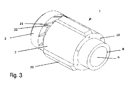
A first exemplary embodiment of the drilling turbine 1 according to the
invention is explained in more detail with reference to figure 3, figure 4,
figure 5, figure 6 and figure 7.
The drilling turbine 1 has a housing 2, a drive shaft 6 and a turbine impeller
3 and has a modular design. The drilling turbine 1 is dimensioned in such a
way that it can be passed together with a fitted milling head 4 or drill bit 5
through the deflection shoe 29. In the illustrated exemplary embodiment,
the housing can have a diameter of about 36 mm and a length of about
42 mm.
The housing 2 has a first end at which the drilling tool or a clamping tool
designed to receive the drilling tool is located. Furthermore, the housing 2
has an opposite second end at which the second hose coupling 8 is
located. Via this coupling, the drive fluid can be introduced into the
supply line 9. During operation, the drive fluid is allowed to flow against
the
turbine impeller 3, as a result of which the turbine impeller 3, the drive
shaft
6 and the milling head 4 or the drill bit 5 rotate with identical angular
velocity.
As can be seen in figures 3 and 4, three guide skids 20, which are regularly
spaced in the circumferential direction, are arranged on the housing 2 of
CA 03177009 2022- 10- 26
20
the drilling turbine 1 and have the same or an outer diameter which is
slightly smaller than that of the milling head 4 or the drill bit 5. This
allows
the drilling turbine 1 to be advanced through the resulting directional drill
hole 38.
As can be seen in figures 5 and 6, the supply line 9 is divided into six sub-
supply lines 10, which extend radially outward in the housing 2. From the
sub-supply lines 10, six return lines 11 extend to the rear side of the
housing
2, where each of them opens into a return opening 18. During the
operation of the drilling turbine, the return lines generate a feed force
which engages the drilling tool with the material to be cut. In other
embodiments of the invention, the number of return openings 18 can be
greater or smaller. The invention does not teach the use of exactly 6 return
openings as a solution principle.
As can best be seen from the sectional views shown in figure 6 and figure
7, the drilling turbine 1 has six drive lines 12, which are uniformly arranged
along the circumference in the housing and extend from each of the six
sub-supply lines 10 via a branch 41 to the first side of the housing 2. At the
first side of the housing 2, each drive line12 opens into a drive mouth 19.
The drive fluid exiting via the drive mouth 19 impinges on the turbine
impeller 3 where it generates a drive torque. In other embodiments of the
invention, the number of drive mouths 19 can be greater or smaller. The
invention does not teach the use of exactly 6 drive mouths as a solution
principle.
Furthermore, figure 7 shows that the turbine impeller 3 is provided with a
plurality of inclined baffle elements 21, each having a baffle surface 22.
The baffle elements 21 can form a constant pressure blading of the
turbine impeller 3. Figure 7 also shows that the drive line 12 has a
longitudinal portion which includes an angle of about 20 to about 70
CA 03177009 2022- 10- 26
21
with respect to the longitudinal axis of the drilling turbine. This angle is
selected in such a way that the longitudinal portion is approximately
parallel to the normal vector of the baffle surfaces. As a result, the
generated torque and/or rotational speed can be increased.
Figures 6 and 7 also show that the turbine impeller 3 is openly arranged on
the housing 2 or is not enclosed by a housing wall in the radial direction.
This allows the drive fluid and contaminants to be easily discharged
without causing the turbine impeller 3 to jam.
Furthermore, figure 6 shows a mounting chamber 16 in which the drive
shaft 6 is rotatably mounted on the longitudinal axis X with at least one
optional ball bearing 37. A connecting line 13 is arranged between the
supply line 9 and the mounting chamber 16, along the longitudinal axis X
and allows a part of the drive fluid F to pass through. As a result, the
mounting chamber 16 and/or the at least one ball bearing 37 can be
flushed with a portion of the drive fluid F. Furthermore, the at least one
ball
bearing 37 can be cooled. Finally, the drive fluid F can provide a
hydrodynamic mounting support for the drive shaft 6.
The drive shaft 6 has at least one optional hollow drill hole 25 along the
longitudinal axis X, through which a passage of part of the drive fluid F is
also possible. As shown in figure 6, the turbine impeller 3 is aligned
coaxially with the drive shaft 6 via a shaft-hub connection 24 and is fixed
thereto. A hollow drill hole 25 is formed in the turbine impeller 3 and allows
the passage of a portion of the drive fluid F. A clamping tool 32 for the
drilling tool is provided on the side of the turbine impeller 3 facing away
from the housing 2. Thus, the drive fluid exiting through the hollow drill
hole
25 can be used to cool the drilling tool and/or to remove the drill hole
cuttings. In some embodiments of the invention, the drive fluid exiting at
the front can cause rock removal.
CA 03177009 2022- 10- 26
22
The course of the drive fluid in the drilling turbine 1 is indicated by the
arrows F. The supplied flow of the drive fluid F passes from the second hose
coupling 8 into the supply line 9, where the flow is divided into the
exemplarily 6 sub-supply lines 10 and passes in each case to a branch 41.
There the flow is divided in each case again into the drive lines 12 and the
return lines 11. The fluid flow Fa emerges from the drive mouths 19 of the
drive lines 12 of the housing 2 in the form of fluid jets Fdrive and, through
corresponding alignment of the drive mouths 19, strikes the baffle surfaces
22 of the baffle elements 21, as a result of which the turbine impeller 3
including the milling head 4 is driven or set in rotation. The fluid flow Fb
emerges from the return openings 18 of the return lines 11 of the housing 2
in the form of fluid jets Frefum, which, due to a corresponding alignment of
the return openings 18, generate on the drilling turbine 1 a feed force
which acts along the longitudinal axis X in the direction of the milling head
4.
Finally, a fluid flow Fc enters the mounting chamber 16 from the supply line
9 through the connecting line 13.1n the mounting chamber 16, this fluid
flow Fc splits into two partial flows Fd and Fe. The fluid flow Fd flows
through the open ball bearings 37, which are thereby lubricated and/or
cooled. Subsequently, the fluid flow Fd exits at the front of the housing 2.
The fluid flow Fe flows out of the mounting chamber 16 and first through
the hollow drill holes 25 of the drive shaft 6 and the turbine impeller 3 and
then exits from the flushing opening 40. From there, it can be directed via
flushing channels in the drilling tool to its tool cutting edges so that the
fluid
flow Fe as a drilling fluid ensures drill hole bottom cleaning and cooling of
the drilling tool 4 or 5.
The diameters of the supply line 9, the drive lines 12, the return lines 11,
the
connecting line 13 and the hollow drill holes 25 of the drilling turbine 1 are
CA 03177009 2022- 10- 26
23
selected in such a way that sufficient feed force, torque, rotational speed
and flushing fluid are provided. By optimizing the number and/or the cross-
sections of the lines, an advantageous ratio of the parameters to one
another can be set, as a result of which long operating times of the drilling
turbine 1 are possible with the highest possible drilling progress. In some
embodiments of the invention, individual drive mouths 19 and/or return
openings 18 can be provided with threaded inserts so that they can be
easily closed with appropriate screw caps. This allows the drilling turbine 1
to be adapted to different operating conditions. For example, individual
return openings 18 can be closed so that drilling operations can be
carried out at high rotational speed or high torque and low feed force. For
drilling operations in other geological formations, individual drive mouths
can be closed to lower the rotational speed or torque and increase the
feed force in return.
With reference to figure 8, figure 9, figure 10, figure 11 and figure 12, a
second exemplary embodiment of the drilling turbine 1 according to the
invention is explained in more detail. Identical features of the invention are
followed by the same reference signs so that the following description is
limited to the essential differences.
According to the second exemplary embodiment, the drilling turbine 1
according to the invention has essentially two differences from the first
exemplary embodiment described in figures 3 - 6. These two differences
are described individually below. It should be noted that they need not
always be realized together in one embodiment. The present invention
also extends to a third embodiment and a fourth embodiment which has
only one of the below described differences with respect to the first
embodiment.
CA 03177009 2022- 10- 26
24
As is clear from figure 8 and figure 11, in contrast to the first embodiment,
the housing 2 does not only have a single supply line 9. On the contrary, a
first supply line 91 and a second supply line 92 are provided in the housing
2. In some embodiments of the invention, the first supply line 91 and the
second supply line 92 can be arranged concentrically or coaxially, as
shown in figures 10 and 11. In other embodiments of the invention, they
can also be arranged side-by-side or one on top of the other on the side
of the housing 2 opposite the turbine impeller 3.
When the drilling turbine 1 is in operation, the first supply line 91 and the
second supply line 92 can each be connected to a hose line or a coaxial
hose line with two conveying devices or pumps. This feature has the effect
that the drive fluid each supplied to the first supply line 91 and the second
supply line 92 can be different in type and/or quantity and/or pressure.
Similarly, a single conveying device or pump can be used if one or both of
the hose lines contain a throttle or control valve which affects the flow
rate or the pressure in the respective line.
As also shown in figure 11, the first supply line 91 is connected to at least
one return line 11 by means of at least one first sub-supply line 101. The
return line 11 opens at a return opening 18, as described above. The return
opening 18 opens at the side of the housing 2 opposite the turbine
impeller 3, as described above. Unlike the first embodiment described
above, the drive fluid cannot flow from the first supply line 91 to the
turbine
impeller 3 via a drive line 12 when the drilling turbine 1 is in operation.
Furthermore, it can be seen from figure 11 and figure 12 that the second
supply line 92 is connected to at least one drive line 12 by means of at
least one second sub-supply line 102. The drive line 12 is designed to direct
the drive fluid at a predeterminable angle via at least one drive mouth 19
onto the baffle surfaces 22 of the baffle elements 21 of the turbine impeller
CA 03177009 2022- 10- 26
25
3, as a result of which the turbine impeller 3 including the milling head 4 is
driven or set in rotation. Unlike in the first embodiment described above,
however, the drive fluid cannot flow from the second supply line 92 via a
return line 11 to a return opening 18 during the operation of the drilling
turbine 1.
Since the drive fluid supplied to the first supply line 91 and the second
supply line 92 can each be different in terms of type and/or quantity
and/or pressure, these features of the second embodiment allow the drive
torque or drive power of the drilling turbine 1 to be controlled
independently of the feed force. As a result, the service life of the tool can
be prolonged and/or the advance can be accelerated. Moreover, it is
possible to adjust the drilling turbine 1 dynamically during operation to the
rock encountered in each case. For this purpose, the drill hole cuttings
discharged from the drill hole can be separated and analyzed in order to
adjust the operating conditions.
As shown in figures 9 and 11, the turbine impeller 3 has six openings 390 in
which at least one weight 39 can be received. In the illustrated exemplary
embodiment, the openings 390 have a circular cross-section. In other
embodiments of the invention, the openings 390 can also have a
polygonal cross-section. In some embodiments of the invention, the
number of openings can be between about 2 and about 16 or between
about 4 and about 10. The invention does not teach the use of exactly six
openings 390 as a solution principle. In yet another embodiment, at least
one opening can be introduced as an annular groove into the turbine
impeller 3.
The weights 39 can have a different size and/or be made of different
materials which, for example, have different densities. In the application of
the drilling turbine 1, the operator can be provided with an assortment of
CA 03177009 2022- 10- 26
26
different weights from which the operator may select. The weights 39 can
be secured in the openings 390 by press-fitting, inserting, bolting, gluing,
and/or otherwise. In the same manner as described above for a turbine
impeller 3, the milling head 4 and/or the drill bit 5 and/or the clamping tool
23 can also be provided with openings 390.
By selecting the weights 39, which are inserted into and secured in the
respective openings 390, the rotating parts can be balanced so that the
drilling turbine 1 exhibits smooth running. In other embodiments of the
invention, different weights having different masses can be inserted into
the openings so that the drilling turbine 1 exhibits imbalance. This feature
has the effect that the center of the cutting edge of a drill bit 5 or a
milling
head 4, which is located on the axis of rotation, is not stationary in the
radial direction of the drilling turbine. The center of the cutting edge of
the
drill bit 5 or the milling head 4 rather describes approximately a circular
path in the material to be cut.
The cutting speed of a rotating cutting tool increases linearly with radius,
i.e. at the center point of the cutting edge of a known drill bit 5 or milling
head 4, the cutting speed is zero and the removal is accordingly low. This
low removal limits the processing time for the entire drilling operation. Due
to the imbalance of the drilling turbine 1 used according to the invention,
the center point of the cutting edge of the drill bit 5 or of the milling head
4 describes approximately a circular path in the material to be cut. Each
point of this circular path is traveled over in further machining phases by
other partial surfaces of the drill bit 5 or the milling head 4 at a higher
cutting speed so that the removal rate increases when considered over
the entire cross-section of the drill hole, and the machining times can be
reduced.
CA 03177009 2022- 10- 26
27
Of course, the invention is not limited to the illustrated embodiments.
Therefore, the above description should not be regarded as restrictive but
as explanatory. The following claims should be understood in such a way
that an indicated feature is present in at least one embodiment of the
invention. This does not exclude the presence of further features. Provided
that the claims and the above description define "first" and "second"
embodiments, this designation is used to distinguish between two similar
embodiments without determining a ranking order.
CA 03177009 2022- 10- 26