Note: Descriptions are shown in the official language in which they were submitted.
CA 03180102 2022-10-12
WO 2021/243012 PCT/US2021/034503
SEALING SYSTEM FOR A MACHINE FOR THERMAL TREATMENT OF BULK
MATERIAL
FIELD OF THE INVENTION
[0001] The present invention relates to a machine for thermal treatment
of bulk material.
More specifically, the disclosure further relates to a sealing system for the
machine for thermal
treatment of bulk material.
BACKGROUND ART
[0002] Machines for thermal treatment of bulk material, such as a
sintering or a
pelletizing system, are known in the art. These machines are configured to
transform the bulk
material, or pelletized concentrate, into hardened pellets that e.g. can be
used as blast furnace
feed or direct reduction furnace feed. The machines comprise a furnace and a
plurality of pallet
cars, wherein the pallet cars are arranged for transporting the bulk material
into the furnace. The
machines comprise different heating and cooling zones and the pallet cars are
arranged for
transporting the bulk material through the different zones of the machine such
that hardened
pellets are produced.
[0003] A problem with the machines is that a gap is defined between the
pallet cars and
the furnace when the pallet cars are traveling through the furnace. A drawback
with this gap is
that dust and other particulate matter as well as hazardous gases can escape
the furnace and
tramp air can enter the hot gases within the furnace.
[0004] In an attempt to meet this problem, US Patent Application
U52293904A suggests
maintaining a sealing system with a drop bar seal design being arranged
between a traveling
grate and a gas collecting hood. The drop bar seal design defines continuous
troughs along the
sides of the traveling grate for carrying dust out of the hood. US Patent
Application
U520150233641 Al suggests maintaining a sealing system with a spring-loaded
sealing strip
contacting a planar sealing surface being arranged along the furnace. However,
with the
solutions disclosed by US1183394 A and U520150233641 Al there is a need in the
art for
improvements in terms of increased sealing efficiency and increased
durability.
1
CA 03180102 2022-10-12
WO 2021/243012 PCT/US2021/034503
SUMMARY
[0005] It is an object to mitigate, alleviate or eliminate one or more of
the above-
identified deficiencies in the art and disadvantages singly or in any
combination and solve at
least the above-mentioned problem.
[0006] According to a first aspect there is provided a machine for
thermal treatment of
bulk material, comprising:
[0007] a stationary furnace which presents a support structure, and
[0008] a plurality of pallet cars traveling through the furnace along a
traveling direction,
said plurality of pallet cars together defining, at a lateral side thereof, a
common engagement
surface which extends through the furnace along the traveling direction,
[0009] wherein a gap is defined between the support structure of the
furnace and the
common engagement surface of the plurality of pallet cars, said gap having a
gap length along
the traveling direction, the machine further comprising:
[0010] a sealing system comprising:
[0011] one or more drop bars distributed after each other along the
traveling direction;
[0012] wherein each drop bar of the one or more drop bars includes a
brush arranged on
the drop bar such that the brush is configured to be in engagement with the
common engagement
surface such that the one or more drop bars covers the gap over at least parts
of the gap length.
[0013] By the term "bulk material" is here meant any metal ore. Given as
a non-limiting
example, bulk material may be iron ore, copper ore, zinc ore, phosphate ore or
any other metallic
or non-metallic mineral ore normally treated within the mining industry.
[0014] By the phrase "machine for thermal treatment" is here meant any
machine
performing any type of treatment involving elevating the temperature of the
bulk material. Such
thermal treatment may be but is not limited to pelletizing or sintering. By
way of example, the
bulk material may be filled into the pallet cars which subsequently travel
along a track through a
furnace. The furnace may comprise one or more treatment zones. Each treatment
zone is adapted
for a specific thermal treatment process of the bulk material. Given as non-
limiting examples,
thermal treatment in the different zones may involve heating, firing, drying
or cooling the bulk
material. The machine may comprise one or more wind boxes arranged in the
zones of the
furnace, below the track of the pallet cars and by suction generate a flow of
the hot air or gas
above the pallet cars through the bulk material. The machine may be a straight
grate furnace.
2
CA 03180102 2022-10-12
WO 2021/243012 PCT/US2021/034503
[0015] By the term "support structure" is here meant a steady and
stationary part of the
furnace that may allow mounting or attachment of other parts thereto. Given
only as examples, a
support structure may be a part of a wall of the furnace or a metal framework.
Herein, the
support structure serves to support one or more parts of the sealing system.
[0016] By the term "drop bar" is here meant a stationary rigid part of
the sealing system.
The drop bar may be of a rectangular shape, wherein the length of the drop bar
is substantially
longer than the width and the height of the drop bar. Herein, the length of
the drop bar is the
dimension of the drop bar in the traveling direction of the pallet cars. Given
only as example, the
drop bar may be a metal framework of the sealing system. The one or more drop
bars may be
distributed after each other along the traveling direction so as to form a
sealing surface. Each
drop bar of the one or more drop bars may have an elongate extension. Each
drop bar of the one
or more drop bars may be aligned such that the elongate extension is parallel
with the traveling
direction. Each drop bar of the one or more drop bars may be slidably
connected to the
support structure of the furnace. Preferably, each drop bar is slidably
connected to the
support structure such that the drop bar is displaceable in a vertical, or
substantially
vertical, direction. This implies that each drop bar may be displaceable in a
direction
transverse to the common engagement surface. For some embodiments, the drop
bars
may be forced, by gravity, to be in engagement with the common engagement
surface.
[0017] By the term "brush" is here meant a part of the drop bar
comprising a plurality of
bristles. The bristles are arranged such as a brush seal is provided. The
length of the bristles may
be substantially longer than the thickness of the bristles. Herein, the length
of the bristles is the
dimension perpendicular to the traveling direction of the pallet cars.
[0018] The sealing system may be advantageous as it seals the gap between
the support
structure of the furnace and the common engagement surface of pallet cars,
wherein the gap
occurs when the pallet cars are traveling along the traveling direction
through the furnace. The
sealing system may cover the gap over at least parts of the gap length such as
it prevents dust
from escaping and tramp air from entering the hot gases. The sealing system
according to the
present disclosure is particularly advantageous in that it combines any
conventional drop bar seal
design with the brush such as a more efficient and a more durable seal will be
provided
compared to conventional arrangements.
3
CA 03180102 2022-10-12
WO 2021/243012 PCT/US2021/034503
[0019] A further advantage of the sealing system of the disclosure is
that a more efficient
and flexible sealing system is achieved compared to conventional arrangements.
By this
arrangement, the sealing system is efficiently adjusted to uneven surfaces by
reason of the
slidable connection and the flexibility of the brush. By way of example,
uneven surfaces may be
the result of uneven height positioning of the pallet cars or of the common
engagement surfaces
thereof, or it may be a result of material getting stuck between the common
engagement surface
and the brush. In case of an uneven surface causing an individual part of the
brush to lose contact
with the common engagement surface of the pallet car, it does not affect
adjacent parts of the
brush. Consequently, adjacent parts of the brush may continue to be in contact
with the common
engagement surface, maintaining the seal to a higher degree than compared to
conventional seal
systems based on drop bars or long flexible seals, which would create large
leaks through the
seal in similar situations since such conventional seal systems cannot adjust
the seal efficiently
enough to uneven surfaces.
[0020] Yet a further advantage, since the sealing system will be exposed
to high
temperatures within some zones of the furnace, may be that cooling air can get
through the brush
and thereby cool the brush in an easy way. Further, including the brush in the
sealing system will
provide for a sealing system which is good to endure heat, and hence, a more
durable seal is
achieved.
[0021] In the manner described above fuel and power efficiency of the
machine is
increased. By the present arrangement, energy savings of up to 10% may be
provided, compared
to a machine for thermal treatment of bulk material without such a sealing
system with brushes.
[0022] Yet a further advantage of the disclosed sealing system is that it
is possible to
replace one brush within the sealing system without the need of replacing the
whole sealing
system. By this arrangement, it may be easy to perform maintenance operations
to the sealing
system, and especially to the brush.
[0023] Yet a further advantage with the disclosed design is that the
brush is equally well
capable of moving over the common engagement surface independent on the
traveling direction
of the pallet cars. Thus, even if there typically is one specific travelling
direction used during
operation of the machine, the need to operate the machine in reverse, e.g.
during maintenance,
will be equally possible.
4
CA 03180102 2022-10-12
WO 2021/243012 PCT/US2021/034503
[0024] The brush may comprise a plurality of brush bristles which are
each attached to a
brush element. The brush element may be an elongated structure having a
substantially
rectangular cross section but may alternatively have a rounded cross section.
[0025] According to some embodiments, brush bristles of the brush are
made of stainless
steel. For alternative embodiments, the brush bristles of the brush are made
of regular steel, or
synthetic polymers such as Nylon.
[0026] Preferably, the bristles are made of stainless steel. This
material is durable and
withstands high temperature well. Also, the material is flexible enough for
the sealing system to
efficiently adjust to uneven surfaces.
[0027] According to some embodiments, brush bristles of the brush has a
length of at
least 20 mm, preferably between 20 and 100 mm, and more preferably 50 mm.
[0028] According to some embodiments, each drop bar further comprises a
drop bar
structure slidably connected to the support structure of the furnace, wherein
the brush is carried
by the drop bar structure. This implies that the drop bar structure may
correspond to a
conventional drop bar. The drop bar structure may, however, be structurally
different than a
conventional drop bar. This is further elaborated on herein.
[0029] By the term "slidably connected" is here meant a connection
wherein the drop bar
structure being connected to the support structure in a way that the drop bar
structure can be
moved smoothly along a surface in relation to the support structure. Herein,
the drop bar
structure allows to move in a vertical direction, wherein the vertical
direction is perpendicular to
the common engagement surface. The connection defines how much the drop bar
structure is
allowed to move in the vertical direction in relation to the drop bar
structure. This slidable
connection allows for the brush to be moved in the vertical direction as well.
[0030] By the term "carried by the drop bar structure" is here meant that
the brush is
attached to, or clamped by, the drop bar structure, wherein the drop bar
structure is arranged to
keep the brush in place.
[0031] According to some embodiments, the brush protrudes out from the
drop bar
structure such that a clearance is formed between the drop bar structure and
the common
engagement surface.
CA 03180102 2022-10-12
WO 2021/243012 PCT/US2021/034503
[0032] According to some embodiments, the clearance between the drop bar
structure
and the common engagement surface is at least 1 mm, preferably 5 to 20 mm, and
more
preferably 10 mm.
[0033] An advantage with these embodiments may be that the sealing system
is further
efficient. By this arrangement, the common engagement surface may have an
uneven surface
without the drop bar structure being in engagement with the common engagement
surface. This
arrangement will provide for less wear one wear parts and thus, an increased
life time of the
sealing system.
[0034] According to some embodiments, the drop bar structure of each drop
bar of the
one or more drop bars comprises a recess configured to receive the brush
therein.
[0035] According to some embodiments, each drop bar of the one or more
drop bars
further comprises a fastening plate configured to connect the brush to the
drop bar structure. The
brush may be connected to the drop bar structure by clamping. The brush may be
directly
clamped between the fastening plate and the drop bar structure. Alternatively,
the brush may be
held by a further element which, in turn, is clamped, between the fastening
plate and the drop bar
structure, as will be detailed later.
[0036] By the term "clamped" is here meant that the brush is attached or
fastened
between the drop bar structure and the fastening plate in order to be kept in
place. The brush may
be clamped towards the drop bar structure using bolts or screws.
[0037] An advantage with these embodiments may be that it is possible to
attach or
detach the brush from the drop bar structure in an easy and user-friendly way.
[0038] According to some embodiments, each drop bar of the one or more
drop bars
further comprises a brush holder configured to hold the brush and wherein the
fastening plate is
configured to clamp the brush holder towards the drop bar structure.
[0039] An advantage with these embodiments may be that it is easier to
attach or detach
the brush from the drop bar structure than if the brush is mounted directly to
the drop bar without
the use of a brush holder. The brush holder may be tailored so as to perfectly
fit a specific kind
of brush. This allows for mounting different kinds of brushes to the exact
same drop bar structure
without having to modify it. Instead, it is possible to select another kind of
brush holder capable
of holding the specific brush. The brush holders may then be attached to the
drop bar structure in
the exact same way, independent on the kind of brush mounted therein.
6
CA 03180102 2022-10-12
WO 2021/243012 PCT/US2021/034503
[0040] According to some embodiments, the brush is arranged on the drop
bar such that
brush bristles of the brush are directed substantially perpendicular to the
common engagement
surface.
[0041] An advantage with these embodiments may be that it is possible to
insert and/or
remove the brush from the drop bar structure in an easy way. By this
arrangement, the brush may
seal the gap, and especially the clearance in an efficient way.
[0042] According to some embodiments, the brush is arranged on the drop
bar such that
brush bristles of the brush form an oblique angle with the common engagement
surface.
[0043] An advantage with these embodiments may be that it provides for an
even more
efficient sealing system compared to when the bristles are directed
perpendicular to the common
engagement surface. By this arrangement, a more flexible brush seal may be
provided as the
brush bristles more easily adjust to the shape of the common engagement
surface.
[0044] According to some embodiments, the machine further comprises a
further sealing
system connected to the support structure of the furnace and arranged along
the traveling
direction, the further sealing system being arranged to be in engagement with
the common
engagement surface so as to cover the gap over at least parts of the gap
length, and wherein the
further sealing system is arranged at a spaced distance from the sealing
system such that an
elongate cavity is formed therebetween.
[0045] The further sealing system may be advantageous as it allows
increasing the
overall sealing efficiency. Moreover, it allows establishing a high-pressure
zone between the
sealing systems to further prevent gas penetrating the sealing systems. This
may be of
importance especially in situations where it is unavoidable to operate a
process or a portion of a
process of the machine at higher pressure than the ambient pressure outside of
the machine. If
purging the double seal arrangement with air or another suitable purge gas at
a higher pressure
than each one of the process and the ambient external pressure, the purge gas
will leak into the
process and out into the environment, which will effectively prevent process
gas from reaching
the environment.
[0046] According to some embodiments, the further sealing system
comprises:
[0047] a series of leaf members which are partially overlapping so as to
form a sealing
surface, wherein each leaf member of the series of leaf members is connected
to the support
7
CA 03180102 2022-10-12
WO 2021/243012 PCT/US2021/034503
structure at a first end thereof, and in engagement with the common engagement
surface at a
second, opposite, end thereof.
[0048] By the term "leaf member" is here meant an individual member of a
series of leaf
members that together form a flexible seal. A leaf member is a substantially
planar member with
a thickness significantly smaller than the length and width of the leaf
member. The width of a
leaf member is the dimension of the leaf member in the traveling direction of
the pallet cars,
whereas the length of a leaf member is a dimension of the leaf member in a
direction
perpendicular to the traveling direction. The leaf member may have a
substantially rectangular or
squared shape, but is not limited to these shapes and may also have an oval,
circular, triangular
or any other planar shape. The leaf member may be made of a flexible material,
such as to
provide a spring-like or self-biasing function.
[0049] According to some embodiments, the further sealing system
comprises a further
one or more drop bars distributed after each other along the traveling
direction.
[0050] According to some embodiments, each drop bar of the further one or
more drop
bars includes a brush arranged on the drop bar structure such that the brush
is configured to be in
engagement with the common engagement surface such that the further one or
more drop bars
covers the gap over at least parts of the gap length.
[0051] According to some embodiments, the sealing system and the further
sealing
system is arranged in parallel to each other so as to cover the gap along a
common gap width
which extends over at least a firing zone and a cooling zone of the furnace.
[0052] In the transition from the firing zone and the cooling zone, there
may be arranged
an after firing zone. Leakage from this zone may cause hazards as combustible
gases from the
furnace may mix with oxidants from ambient air, thereby creating a risk of
unwanted ignition.
[0053] An advantage with these embodiments may be that leakage in these
zones may be
minimized or eliminated, hence minimizing the risk of unwanted ignition or
explosion. Thus, by
this arrangement, the seal may be even further improved.
[0054] A further advantage of these embodiments may be that the same
sealing
arrangement continues from the firing zone into the cooling zone such that no
gaps are created in
the transition between the firing zone and the cooling zone. By the present
arrangement, a
sealing system that may minimize leakage either into, or out from, the furnace
may be provided.
8
CA 03180102 2022-10-12
WO 2021/243012 PCT/US2021/034503
[0055] A further advantage with these embodiments may be that the thermal
load on the
outmost of the two sealing systems may be lowered.
[0056] A further advantage with these embodiments may be that the sealing
system may
be arranged along full length of the furnace, and that the further sealing
system may optionally
be arranged only in zones in which a dual sealing system may be required, such
as in the firing
zone and the cooling zone.
[0057] According to some embodiments, there may be further provided a gas
flow in the
elongate cavity between the sealing system and the further sealing system. The
gas in the gas
flow may be, but is not limited to, air, or inert gases such as Nitrogen, or
any other suitable gas.
Given as non-limiting examples, the gas may be supplied to the elongate cavity
from a supply of
pressurized air, or air from the cooling zone may be supplied.
[0058] An advantage with these embodiments may be that the gas flow may
cool the
sealing system and the further sealing system, enabling the use of even higher
temperatures in
the furnace than would otherwise be possible in order not to thermally damage
the sealing
system or the further sealing system.
[0059] A further advantage with these embodiments may be that, when
providing an air
flow through the cavity formed between the sealing system and the further
sealing system, the
high pressure in the cavity will be easier to keep at the right level.
[0060] According to a second aspect, there is provided a method for
attaching a brush to
a drop bar in a sealing system for a machine for thermal treatment of bulk
material,
[0061] wherein the sealing system comprises one or more drop bars being
configured to
be distributed after each other along a traveling direction, and
[0062] wherein the machine comprises a stationary furnace which presents
an attachment
structure, and a plurality of pallet cars traveling through the furnace along
a traveling direction,
said plurality of pallet cars together defining, at a lateral side thereof, a
common engagement
surface which extends through the furnace along the traveling direction,
wherein a gap is defined
between the attachment structure of the furnace and the common engagement
surface of the
plurality of pallet cars, the method comprising:
[0063] dismantling at least one drop bar of the one or more drop bars
from the machine,
[0064] attaching a brush, or a brush holder which carries the brush, to
the at least one
drop bar, and
9
CA 03180102 2022-10-12
WO 2021/243012 PCT/US2021/034503
[0065] mounting said at least one drop bar back on the machine,
[0066] wherein the brush or brush holder is attached to the drop bar such
that the brush is
configured to be in engagement with the common engagement surface when in use
on the
machine.
[0067] According to some embodiments, the method further comprises:
[0068] milling a recess in each drop bar of the one or more drop bars,
and
[0069] inserting the brush or the brush holder into the recess.
[0070] According to some embodiments, attaching the brush or the brush
holder to the at
least one drop bar comprises clamping the brush or the brush holder towards
the at least one drop
bar by means of a fastening plate.
[0071] According to a third aspect, there is provided a sealing system
for a machine for
the thermal treatment of bulk material,
[0072] wherein the machine comprises a stationary furnace which presents
an attachment
structure, and a plurality of pallet cars traveling through the furnace along
a traveling direction,
said plurality of pallet cars together defining, at a lateral side thereof, a
common engagement
surface which extends through the furnace along the traveling direction,
wherein a gap is defined
between the attachment structure of the furnace and the common engagement
surface of the
plurality of pallet cars, the sealing system comprising:
[0073] one or more drop bars being configured to be distributed after
each other along
the traveling direction;
[0074] wherein each drop bar of the one or more drop bars includes a
brush arranged on
the drop bar such that the brush is configured to be in engagement with the
common engagement
surface such that the one or more drop bars covers the gap over at least parts
of the gap length.
[0075] Effects and features of the second and third aspects are largely
analogous to those
described above in connection with the first aspect. Embodiments mentioned in
relation to the
first aspect are largely compatible with the second and third aspect. It is
further noted that the
inventive concepts relate to all possible combinations of features unless
explicitly stated
otherwise. A further scope of applicability of the present invention will
become apparent from
the detailed description given below. However, it should be understood that
the detailed
description and specific examples, while indicating preferred embodiments of
the invention, are
CA 03180102 2022-10-12
WO 2021/243012 PCT/US2021/034503
given by way of illustration only, since various changes and modifications
within the scope of
the invention will become apparent to those skilled in the art from this
detailed description.
[0076] Hence, it is to be understood that this invention is not limited
to the particular
component parts of the device described or steps of the methods described as
such device and
method may vary. It is also to be understood that the terminology used herein
is for purpose of
describing particular embodiments only and is not intended to be limiting. It
must be noted that,
as used in the specification and the appended claim, the articles "a", "an",
"the", and "said" are
intended to mean that there are one or more of the elements unless the context
clearly dictates
otherwise. Thus, for example, reference to "a unit" or "the unit" may include
several devices, and
the like. Furthermore, the words "comprising", "including", "containing" and
similar wordings
does not exclude other elements or steps.
BRIEF DESCRIPTION OF THE DRAWINGS
[0077] The above, as well as additional objects, features and advantages
of the present
invention, will be better understood through the following illustrative and
non-limiting detailed
description of embodiments of the present invention, with reference to the
appended drawings,
where the same reference numerals may be used for similar elements, and
wherein:
[0078] Fig. lA is a perspective view of a machine for thermal treatment
of bulk material.
[0079] Fig. 1B is a cross section of a machine for thermal treatment of
bulk material.
[0080] Figs 2A-2B illustrate a sealing system comprising a series of leaf
members, as
arranged when connected to the support structure of the machine.
[0081] Fig. 3 illustrates a sealing system, providing some more details
on the sealing
functionality of the concept of using leaf seals.
[0082] Fig. 4 illustrates a drawback that would occur if a more
conventional long flexible
seal member were to be used.
[0083] Fig. 5A illustrates parts of the sealing system comprising a
series of leaf
members.
[0084] Fig. 5B illustrates three overlapping leaf members.
[0085] Fig. 6A illustrates parts of the sealing system comprising two
series of leaf
members and a series of flexible blanket members.
[0086] Fig. 6B illustrates three overlapping leaf members and a flexible
blanket member.
11
CA 03180102 2022-10-12
WO 2021/243012 PCT/US2021/034503
[0087] Fig. 7 illustrates part of a machine comprising a sealing system.
[0088] Fig. 8A is a perspective view of a sealing system which comprises
a drop bar
including a drop bar structure and a brush.
[0089] Fig. 8B illustrates a front view of the sealing system illustrated
in Fig. 8A.
[0090] Fig. 8C illustrates a cross section of the sealing system
illustrated in Fig. 8A and
8B, wherein the brush forms an oblique angle to a common engagement surface.
[0091] Fig. 9 illustrates a cross section of a sealing system, wherein
the brush is
perpendicular to a common engagement surface.
[0092] Figs 10A-10B illustrate an embodiment of a sealing assembly
comprising the
sealing system with a series of leaf members, and a further sealing system
comprising a drop bar.
[0093] Figs 11A-11B illustrate an embodiment of a sealing assembly
comprising the
sealing system with a series of leaf members, and a further sealing system
comprising a drop bar
with a brush.
[0094] Fig. 12 illustrates an embodiment of a sealing assembly comprising
a sealing
system comprising a drop bar including a drop bar structure and a brush, and a
further sealing
system comprising a drop bar.
[0095] Fig. 13 illustrates an embodiment of a sealing assembly comprising
a sealing
system and a further sealing system, both comprising a drop bar including a
drop bar structure
and a brush.
[0096] Fig. 14 illustrates an embodiment of a sealing assembly comprising
a sealing
system and a further sealing system, both comprising a respective series of
leaf members,
together with yet a further sealing system comprising a drop bar.
DETAILED DESCRIPTION OF PREFERRED EMBODIMENTS
[0097] The present invention will now be described more fully hereinafter
with reference
to the accompanying drawings, in which currently preferred embodiments of the
invention are
shown. This invention may, however, be embodied in many different forms and
should not be
construed as limited to the embodiments set forth herein; rather, these
embodiments are provided
for thoroughness and completeness, and fully convey the scope of the invention
to the skilled
person.
12
CA 03180102 2022-10-12
WO 2021/243012 PCT/US2021/034503
[0098] The present disclosure relates to a machine for thermal treatment
of bulk material
and a sealing system for the machine. With reference to Fig. 1 of the present
disclosure, the
machine for thermal treatment of bulk material will be discussed. For the sake
of clarity, a
number of different seal designs that may be used in conjunction with the
machine will be
discussed in the following sections. With reference to Figs 2-6 of the present
disclosure, a
sealing system comprising a leaf seal design will be discussed. With reference
to Figs 7-9 of the
present disclosure, a sealing system comprising a brush seal design will be
discussed. With
reference to Figs 10-14 of the present disclosure, a sealing system comprising
different
combinations of seal designs will be discussed.
[0099] In particular, the present disclosure relates to a single sealing
system according to
the sealing system discussed in connection with Figs 7-9. Further, the present
disclosure also
relates to dual sealing systems, or sealing assemblies, being any combination
of sealing systems
discussed throughout this disclosure in connection with Figs 2-9.
[0100] Figures 1A-1B illustrate a part of a machine 100 for thermal
treatment of bulk
material, such as metal ore. However, it should be understood that only a part
of the machine 100
is illustrated in the figures and hence, the machine 100 may comprise more
features than
discussed herein. The machine 100 may be any machine for thermal treatment of
bulk material
known in the art.
[0101] The machine 100 comprises a stationary furnace 10 configured to
process bulk
material. By processing the material, is herein meant, drying, heating or
cooling the bulk material
using the stationary furnace 10.
[0102] The machine 100 further comprises a plurality of pallet cars 12.
The pallet cars 12
are configured to transport the bulk material through the stationary furnace
10. The pallet cars 12
are traveling through the stationary furnace 10 on a set of rails (not shown).
The pallet cars 12
are traveling through the stationary furnace 10 along a traveling direction
TD. The traveling
direction TD extends along a substantially horizontal direction.
[0103] The pallet cars 12 are arranged with holes in the bottom plate for
receiving a gas
flow through the bottom plate. Although not illustrated in Figs 1A-1B, the
machine 100
comprises an arrangement below the track of the pallet cars 12 that by suction
generates a flow
of hot air or gas above the pallet cars 12 through the bulk material and the
pallet cars 12. Such an
13
CA 03180102 2022-10-12
WO 2021/243012 PCT/US2021/034503
arrangement may be, but is not limited to, wind boxes. Further, generation of
gas or air flow may
alternatively be used for cooling the bulk material in other parts of the
machine 100.
[0104] The stationary furnace 10 presents a support structure 16. The
support structure
16 is a steady and stationary part of the furnace 10, located on either
lateral side of the furnace
10. The support structure 16 is arranged such that when the plurality of
pallet cars 12 travel
through the furnace 10, the lateral sides of the pallet cars 12 pass in the
vicinity of the support
structure 16. The support structure 16 together with the pallet cars 12
defines a portion of the
boundary between the interior of the furnace 10 and the ambient air.
[0105] The plurality of pallet cars 12 together define a common
engagement surface 14.
The common engagement surface 14 extends through the stationary furnace 10
along the
traveling direction TD. The common engagement surface 14 and the support
structure 16 of the
furnace 10 together define a gap 18 therebetween. The gap 18 has a gap length
L along the
traveling direction through the stationary furnace 10 along the traveling
direction TD.
[0106] The machine 100 further comprises a sealing system (not
illustrated in Fig. 1).
The sealing system is configured to seal the gap defined between the common
engagement
surface 14 and the support structure 16 so as to prevent gas, droplets and/or
particulate matter
from passing through the gap 18. The sealing system will be discussed in more
detail in
connection with Figs 2-11.
[0107] Figure 2A illustrates a sealing system 200 as arranged when
connected to the
support structure 16 of the machine 100. As discussed in relation to Figs 1A-
1B, a gap 18
defined between the support structure 16 of the furnace 10 and the common
engagement surface
14 of the plurality of pallet cars 12. A purpose of the sealing system 200 is
to seal the gap 18
between the support structure 16 and the common engagement surface 14, so as
to prevent gas,
droplets and/or particulate matter from passing through the gap 18. In the
present example
embodiment, the sealing system 200 comprises a series 210 of leaf members 212
which are
partially overlapping so as to form a sealing surface. The leaf members 212 in
the present
embodiment have a rectangular shape, however it is conceivable that leaf
members in other
embodiments may have different shapes. The sealing system 200 of the present
embodiment
further comprises a number of brackets 220. In Fig. 2A two brackets 220 are
illustrated, although
it should be understood that only a portion of the machine 100 is illustrated,
and thus the number
of brackets 220 in the full machine 100 may be different. Each of the brackets
220 comprises an
14
CA 03180102 2022-10-12
WO 2021/243012 PCT/US2021/034503
attachment surface 222, onto which a first end 214 of each of the leaf members
212 is connected
to a bracket 220. Further, the brackets 220 are attached to the support
structure 16. In the present
example embodiment, the attachment surface 222 of each of the brackets 220 is
angled with
respect to the engagement surface 14. The angled attachment surface 222
provides self-biasing of
the leaf members 212 attached thereto, towards the common engagement surface
14. The angled
attachment surface 222 may form an angle in relation to the common engagement
surface being
to 50 degree. However, larger, or smaller, angles are also conceivable.
[0108] The leaf members of the disclosure, such as the leaf members 212
may be made
of thin spring steel. A property of such spring steel is that it is resilient
and may thus return to its
original shape despite being subjected to deflection and twisting. Leaf
members of the disclosure
may however alternatively be made of other types of material. By way of
example, the leaf
members may be made of, but are not limited to, stainless steel, iron, copper,
polytetrafluoroethylene or fluoropolymers, such as used in TeflonTM, plastics
and composites
such as steel with a rubber tip.
[0109] As illustrated in Fig. 2A, the otherwise planar leaf members 212
take a bent shape
as a result of the angled attachment surface 222 such that a second end 216 of
each of the leaf
members 212 in engagement with the engagement surface 14 is pushed against the
engagement
surface 14 by the resilient force of the leaf members 212. By the present
arrangement the gap 18
between the support structure 16 and the common engagement surface 14 is
covered and thereby
sealed such as to prevent passage of gas, droplets and/or particulate matter
from the interior of
the furnace to the ambient air, or vice versa.
[0110] Figure 2B illustrates the same sealing system 200 as in Fig. 2A
from a different
point of view. Further to what has been discussed above, Fig. 2B illustrates
that a significant
portion of a length of each of the leaf members 212 is arranged in an
overlapping manner with
the common engagement surface 14. As the plurality of pallet cars 12 travel
through the furnace
an edge 218 of the second end 216 of each of the leaf members 212 may wear
off. If the leaf
members 212 were arranged in a planar manner, the wearing of the edge 218
would eventually
result in loss of contact between the leaf members 212 and the common
engagement surface 14,
whereby the seal across the gap 18 would be impaired. However, as the leaf
members 212 are
arranged to be self-biased into engagement with the common engagement surface
14, the
resilience of each leaf member 212 will push the second end 216 of the leaf
member 212 towards
CA 03180102 2022-10-12
WO 2021/243012 PCT/US2021/034503
the common engagement surface 14 even as the edge 218 wears off. By the
present arrangement,
contact between the leaf members 212 and the common engagement surface 14 is
maintained,
ensuring continued seal.
[0111] Figure 3 illustrates the sealing system 200 providing some more
details on the
sealing functionality of the concept of using leaf seals. A problem of sealing
the gap 18 between
the common engagement surface 14 and the support structure 16 may be that the
engagement
surfaces 14a, 14b, 14c of individual pallet cars 12 (pallet cars not shown in
the present figure),
may be shifted in a vertical direction with respect to each other. Such a
shift may be due to slight
variation in manufacturing of the pallet cars 12 or, more likely, that the
pallet cars 12 sag over
time partly due to a combination of carried heavy load and harsh environment
with extreme
temperatures in the furnace 10. Such a vertical shift is illustrated in Fig. 3
with the individual
engagement surfaces 14a, 14b, 14c having different vertical positions. The
leaf members 212 are
arranged to be in good physical contact with the flat engagement surfaces 14a,
14b, 14c.
However, at a transition from one engagement surface 14a to another engagement
surface 14b,
the common surface is no longer flat due to the difference in vertical
position and thus the leaf
members 212 are deformed to adjust to the shifting structure of the surface
due to the resilience
of the material out of which the leaf members 212 are made. It is illustrated
in Fig. 3 that said
deformation substantially occurs for the individual leaf members 212 at such
transitions, whereas
adjacent leaf members 212 are to a large extent unaffected by the transition
and hence maintain
contact with the engagement surfaces 14a, 14b, 14c. The present arrangement
results in only a
small gap 30 at the transition as a result of deformation of an individual
leaf member 212.
Consequently, only a small leak may result due to differences in vertical
position of the pallet
cars 12, thus maintaining high sealing efficiency.
[0112] Figure 4 illustrates a drawback that would occur if a more
conventional long
flexible seal member 210' were to be used. The situation is similar to the one
just described in
relation to Fig. 3, wherein the engagement surface 14 of individual pallet
cars 12 are shifted in
the vertical direction with respect to each other. Since the long flexible
seal 210' is continuous it
will be affected by the shift not only in the vicinity of the transition
between individual pallet
cars 12, but also along a larger portion of the common engagement surface 14.
This may cause a
significantly larger gap 30' between the long flexible seal member 210' and
the common
16
CA 03180102 2022-10-12
WO 2021/243012 PCT/US2021/034503
engagement surface 14, resulting in significantly larger leak through the seal
than compared to
the sealing system 200 based on a series 210 of leaf members 212.
[0113] Returning now to Fig. 3, a further situation that may occur in
sealing systems of a
machine 100 for thermal treatment of bulk material is illustrated, namely that
pellets may
occasionally get stuck underneath the seal. In Fig. 3, a pellet 20 is
illustrated to be stuck between
the series 210 of leaf members 212 and an individual engagement surface 14b.
The stuck pellet
20 may lift up some of the leaf members 212, which are thus deformed such that
they are bent
upwards. Said deformation substantially occurs for the individual leaf members
212 in contact
with the pellet 20, whereas adjacent leaf members 212 to a large extent are
unaffected by the
stuck pellet 20 and hence maintain contact with the engagement surfaces 14a,
14b, 14c. Similarly
to the situation at the transition between individual pallet cars 12, the
present arrangement results
in only a small gap 40 in the vicinity of the pellet 20 as a result of
deformation of one or a few
individual leaf members 212. Consequently, only a small leak may result due to
the stuck pellet
20, thus maintaining high sealing efficiency.
[0114] Figure 5A illustrates the sealing system 200 viewed in the
traveling direction TD.
The leaf member 212 is illustrated to be connected to the bracket 220 by means
of a bolt 224 and
nut 226 arrangement. Bolts 224 are inserted into through holes of the bracket
220 and into
through holes 217 of the leaf member 212. Nuts 226 are tightened onto the
other end of the bolts
224, attaching the leaf member 212 to the bracket 220. To simplify replacement
of individual
leaf members, the bolts 224 may be pre-welded onto the bracket 220. It should
be understood
that also other means for connecting leaf members 212 to the bracket 220 are
conceivable.
[0115] In Fig. 5A it is further illustrated that the bracket 220 comprise
an attachment
surface 222 onto which the leaf member 212 is connected to the bracket 220.
The attachment
surface 222 is angled with respect to the engagement surface 14. The present
arrangement
provides the leaf member 212 with a curvature which due to the resilience of
the material out of
which the leaf member 212 is made, results in a self-biased state, thereby
pushing the second end
216 of the leaf member 212 towards the engagement surface 14.
[0116] Figure 5B illustrates three leaf members 212a, 212b, 212c viewed
in a direction
perpendicular to the traveling direction TD. The three leaf members 212a,
212b, 212c are
partially overlapping so that a through hole 217 of leaf member 212a coincides
with a through
hole 217 of the adjacent leaf member 212b and so on. The ratio of overlap may
vary between
17
CA 03180102 2022-10-12
WO 2021/243012 PCT/US2021/034503
different embodiments. Figure 5B illustrates that in the present embodiment a
leaf member 212a
overlaps with the consecutive leaf member 212b by typically less than 50%.
[0117] Figure 6A illustrates a sealing system 300 viewed in the traveling
direction TD.
The sealing system comprises brackets 220 each of which having an attachment
surface 222.
Onto the attachment surface 222 is a first series 310 of leaf members 312
connected. The leaf
members 312 in the first series 310 of leaf members 312 are partially
overlapping so as to form a
sealing surface. It should be understood that the first series 310 of leaf
members 312 may be of
the same type as in the series 210 of leaf members 212 in sealing system 200,
or they may be of a
different type.
[0118] Further, the sealing system 300 comprises a series 330 of flexible
blanket
members 332. Each flexible blanket member 332 of the series 330 of flexible
blanket members
332 is connected to the bracket at a first end 334 of the flexible blanket
member 332. The series
330 of flexible blanket members 332 is positioned adjacent the first series
310 of leaf members
312 so as to cover overlapping edges of adjacent leaf members 312. The
flexible blanket
members of the disclosure may be made of, but are not limited to, Neopren
(i.e.
polychloroprene), welding blanket of woven blanket biomass, synthetic polymers
such as Nylon,
woven or nonwoven fiber blanket material, gasket material made of
polytetrafluoroethylene or
fluoropolymers, such as used in TeflonTM.
[0119] Further, the sealing system 300 comprises a second series 340 of
leaf members
342. Each leaf member 342 of the series 340 of leaf members 342 is connected
to the bracket at a
first end 344 of the leaf member 342. It should be understood that the second
series 340 of leaf
members 342 may be of the same type as in the first series 310 of leaf members
312, or they may
be of a different type. The second series 340 of leaf members 342 is
positioned adjacent the
series 330 of flexible blanket members 332 on an opposite side with respect to
the first series 310
of leaf members 312, so as to sandwich the series 330 of flexible blanket
members 332 between
the first series 310 and the second series 340.
[0120] The leaf members 312, 342 and the flexible blanket members 332 are
illustrated
to be connected to the bracket 220 by means of a bolt 224 and nut 226
arrangement. Bolts 224
are inserted into through holes of the bracket 220 and into through holes 317
of the leaf member
312, 342 and the flexible blanket members 332. Nuts 226 are tightened onto the
other end of the
bolts 224, attaching the leaf members 312, 342 and the flexible blanket
members 332 to the
18
CA 03180102 2022-10-12
WO 2021/243012 PCT/US2021/034503
bracket 220. To simplify replacement of individual leaf members, the bolts 224
may be pre-
welded onto the bracket 220. It should be understood that also other means for
connecting leaf
members 312, 342 and the flexible blanket members 332 to the bracket 220 are
conceivable.
[0121] In Fig. 6A it is further illustrated that the bracket 220 comprise
an attachment
surface 222 onto which the leaf members 312, 342 and the flexible blanket
members 332 are
connected to the bracket 220. The attachment surface 222 is angled with
respect to the
engagement surface 14. The present arrangement provides the leaf members 312,
342 and the
flexible blanket member 332 with a curvature which due to the resilience of
the material out of
which they are made, results in a self-biased state, thereby pushing the
second ends 316, 336,
346 in a direction towards the engagement surface 14. In the illustrated
example embodiment,
the flexible blanket member 332 is shorter in length as compared to the leaf
members 312, 342,
such that the flexible blanket member 332 does not extend to reach the edge
318 of the second
end 316 of the leaf member 312. The present arrangement allows the second end
316 of the leaf
member 312 to be in direct engagement with the common engagement surface 14.
An advantage
with the present arrangement is that good sealing effect is provided, since
the engagement of the
leaf members 312 with the common engagement surface 14, which constitute the
primary seal, is
ensured.
[0122] Figure 6B illustrates three leaf members 312a, 312b, 312c viewed
in a direction
perpendicular to the traveling direction TD. The three leaf members 312a,
312b, 312c are
partially overlapping so that a through hole 317 of leaf member 312a coincides
with a through
hole 317 of the adjacent leaf member 312b and so on. The ratio of overlap may
vary between
different embodiments. Figure 6B illustrates that in the present embodiment a
leaf member 312a
overlaps with the consecutive leaf member 312b by typically less than 50%. In
comparison to the
three leaf members 312a, 312b, 312c also a flexible blanket member 332 is
illustrated in Fig. 6B.
As explained in relation to Fig. 6A, also the flexible blanket members 332 are
connected by a
bolt 224 and nut 226 arrangement, using through holes 317 in the flexible
blanket members. The
flexible blanket member 332 is wider than the leaf members 312 such that the
flexible blanket
member 332 covers the three leaf members 312a, 312b, 312c, in the present
embodiment.
[0123] Figure 7 illustrates a sealing system 400 as arranged when
connected to the
support structure 16 of the machine 100. The sealing system 400 is also
illustrated in isolation in
Figs 8A-C. In the example embodiment, the sealing system 400 comprises a drop
bar 402 having
19
CA 03180102 2022-10-12
WO 2021/243012 PCT/US2021/034503
an elongated extension 401 (illustrated in Fig. 8A). The drop bar 402 is
arranged along the
traveling direction TD so as to form a sealing surface S (illustrated in Fig.
8A). However, it
should be understood, as only a part of the sealing system 400 is illustrated
in Fig. 7, the sealing
system 400 may comprise more than one drop bar 402. If the sealing system 400
comprises more
than one drop bar 402, the more than one drop bars 402 are distributed after
each other along the
traveling direction TD so as to form the sealing surface S.
[0124] The drop bar 402 includes a drop bar structure 404 and a brush
406, wherein the
brush comprises a plurality of bristles 407 (illustrated in Fig. 8A). The
brush 406 is carried by
the drop bar structure 404 such that the brush 406 is configured to be in
engagement with the
common engagement surface 14 of the pallet cars 12. In the example embodiment,
the brush 406
is forced, by gravity, to be in engagement with the common engagement surface
14. Other
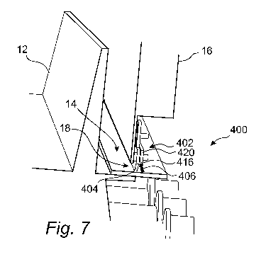
engagement means are however conceivable, such as biasing by e.g. a spring.
The attachment of
the brush to the drop bar structure will be further discussed in relation to
Figs 8C and 9.
[0125] The drop bar structure 404 comprises connecting means 410 for
connecting the
sealing system 400 to the machine 100. As best illustrated in Figs 8A and 8B,
in the example
embodiment, the drop bar structure 404 comprises four connecting means 410,
but it should be
understood, as only a part of the machine 100 and the sealing system 400 is
illustrated in the
figure, that the drop bar structure 404 may comprise any number of connecting
means 410.
Connecting means for drop bars are well known in the art and may for example
be embodied by
an engagement between a pin 411 and an elongate opening 413, as illustrated in
Fig. 8A.
[0126] The drop bar structure 404 and the brush 406 together forms the
sealing surface S
that covers the gap 18 over at least parts of the gap length L.
[0127] Figure 8A illustrates the sealing system 400 in isolation and
provides more details
thereof. The sealing system 400 comprises the drop bar 402, wherein the drop
bar 402 includes
the drop bar structure 404 and the brush 406. In this example embodiment, the
drop bar 402
further comprises a brush holder 416 which is configured to hold the brush
406. A fastening
plate 420 is configured to clamp the brush holder 416 towards the drop bar
structure
404. The fastening plate 420 is clamped towards the drop bar structure 404 by
means of screws
or bolts 422. Fig 8A further illustrates how the brush 406 is configured to be
in engagement with
the common engagement surface 14 (illustrated here by surfaces 14a and 14b of
two adjacent
CA 03180102 2022-10-12
WO 2021/243012 PCT/US2021/034503
pallet cars), of the pallet cars 12. In the example embodiment, it is further
illustrated that the
brush 406 extends over the elongated extension 401 so as to form the sealing
surface S.
[0128] A problem of sealing the gap 18 between the common engagement
surface 14 and
the support structure 16 may be that the engagement surfaces 14a, 14b of
individual pallet cars
12 (pallet cars not shown in the present figure), may be shifted in a vertical
direction with respect
to each other. Such a shift may be due to slight variation in manufacturing of
the pallet cars 12
or, more likely, that the pallet cars 12 sag over time partly due to a
combination of carried heavy
load and harsh environment with extreme temperatures in the furnace. Such a
vertical shift is
illustrated in Fig. 8A with the individual pallet cars 14a, 14b having
different vertical positions.
The bristles 407 of the brush 406 are arranged to be in good physical contact
with the flat
engagement surfaces 14a, 14b. However, at a transition from one engagement
surface 14a to
another engagement surface 14b, the surface is no longer flat due to the
difference in vertical
position and thus the bristles 407 of the brush 406 are deformed to adjust to
the sifting structure
of the surface due to the resilience of the material out of which the bristles
407 of the brush 406
are made. It is illustrated in Fig. 8A that said deformation substantially
occurs for one or more
bristles, independently of the adjacent bristles, at such transitions, whereas
adjacent bristles are
to a large extent unaffected by the transition and hence maintain contact with
the engagement
surface 14a, 14b. The present arrangement results in only a small gap 412 at
the transition as a
result of deformation of one or more bristles of the brush 406. Consequently,
only a small leak
may result due to differences in vertical position of the pallet cars, thus
maintaining high sealing
efficiency.
[0129] Figure 8B illustrates a front view of the sealing system 400
illustrated in Fig. 8A.
Further to what have been discussed above, Fig. 8B illustrates that each of
the connecting means
410 are arranged with a distance from each other. In the example embodiment,
each of the
connecting means 410 are arranged with the same distance from each other,
although it should be
understood that each of the connecting means 410 may be arranged with
different distances from
each other as well.
[0130] Figure 8C illustrates the sealing system 400 viewed in the
traveling direction TD.
In addition to what have been discussed above, Fig. 8C illustrates how the
brush 406 is carried
by the drop bar structure 404 in more detail by means of a dedicated brush
holder 416. The brush
holder 416 has an upper extension arranged to be sandwiched between the drop
bar structure 404
21
CA 03180102 2022-10-12
WO 2021/243012 PCT/US2021/034503
and the fastening plate 420. The lower end of the brush holder 416 is shaped
so as to partially
encompass the brush 406 to keep the brush 406 in a firm grip. In the example
embodiment, the
brush element 409 is shaped so as to be held in a firm position by the brush
holder 416. The
brush holder 416 is fastened in relation to the drop bar structure 404 such
that the brush 406
protrudes out from a bottom end of the drop bar structure 404 towards the
common engagement
surface 14 such as the brush 406 is in engagement with the common engagement
surface 14.
This defines a clearance 418 between the drop bar structure 404 and the common
engagement
surface 14. As can be seen in the Figures, the clearance 418 is covered by the
brush 406 and the
resilient nature of the brush 406 allows the drop bar 402 to keep a more
efficient sealing than a
drop bar having no brush.
[0131] The brush holder 416 is arranged such that the brush 406 forms an
oblique angle a
with the common engagement surface 14. The angle may preferably be within the
range 20-40
degrees, but may alternatively be smaller, or larger.
[0132] Figure 9 illustrates a sealing system 500 according to an
alternative embodiment.
The sealing system 500 has many features in common with the sealing system 400
illustrated in
Figs 8A-8B, namely a drop bar 502 which includes a drop bar structure 504 and
a brush 506.
However, in this example embodiment, the drop bar structure 504 further
comprises a recess 514
for receiving the brush 506. The fastening plate 520 is for this embodiment
received into the
drop bar structure 404 in a further recess 515. This way, the drop bar
structure 504 and the
fastening plate 520 will have upper surfaces being flush with each other. The
brush 506, which
includes brush element 509 and bristles 507, may be clamped towards the drop
bar structure 504
using bolts or screws 522 as illustrated in Fig. 9. The brush 506 is arranged
with respect to the
drop bar structure 504 such that the bristles 507 of the brush 506 are
directed perpendicular, or
substantially perpendicular, to the common engagement surface 14.
[0133] As for Fig. 8C, Fig. 9 illustrates the clearance 418 between the
drop bar structure
504 and the common engagement surface 14 such that the brush 506 is the only
part of the
sealing system 500 that is in engagement with the common support structure 14.
[0134] Figures 8C and 9 illustrate two different example embodiments of
the brush-based
sealing system according to the disclosure, wherein the brush 406, 506 is
arranged in different
ways. However, it should be understood that theses embodiments are only
examples and the
arrangement of the brush is not limited to these embodiments. Thus, for
example, the brush may
22
CA 03180102 2022-10-12
WO 2021/243012 PCT/US2021/034503
be angled in any direction, towards or away from the drop bar structure but
also along the drop
bar structure. Alternative embodiments may include a drop bar including two or
more brushes
arranged parallel to each other. For example, in one embodiment the drop bar
includes two
brushes arranged on opposite sides of the drop bar, wherein each brush forms a
respective
oblique angle with the common engagement surface.
[0135] Figures 10-14 illustrate different embodiments of the sealing
system arranged in
parallel with a further sealing system so as to define a sealing assembly of
the machine.
[0136] The further sealing system may be any of the sealing system
discussed in relation
to Figs 2-9, or alternatively another sealing system not disclosed therein.
The further sealing
system is connected to the support structure 16 of the furnace 10 and arranged
along the traveling
direction TD.
[0137] A purpose of the further sealing system is to seal the gap 18
between the support
structure 16 and the common engagement surface 14, so as to prevent gas,
droplets and/or
particulate matter from passing through the gap 18. The further sealing system
is arranged at a
spaced distance from the sealing system such that an elongate cavity is
formed.
[0138] Figures 10A-10B illustrate an embodiment of a sealing assembly 600
comprising
the sealing system 200 in parallel with a sealing system 70 as arranged when
connected to the
support structure 16 of the machine 100. The sealing system 70 comprises a
drop bar 60 of
conventional type well known in the art. The sealing system 70 is slidably
connected to the
support structure in a manner similar to what has been described herein. The
sealing system 70 is
arranged at a spaced distance from the sealing system 200, at an interior side
of the furnace 10,
such that an elongate cavity 650 is formed between the two sealing systems 70,
200. For a person
skilled in the art, it is conceivable that the sealing system, although
illustrated here as a sealing
system 200, may alternatively be a sealing system 300 according to the
embodiment disclosed in
Figs 6A-6B.
[0139] Figures 11A-11B illustrate an embodiment of a sealing assembly 700
comprising
the sealing system 200 in parallel with the sealing system 400 previously
disclosed herein. As for
sealing assembly 600, the two sealing systems 200, 400 are arranged in
parallel to each other
along the traveling direction TD. The sealing system 400 comprises a drop bar
402 including a
drop bar structure 404 and a brush 406, as previously disclosed in detail with
reference to Figs 7-
8. The sealing system 400 is slidably connected to the support structure 16
via each of the drop
23
CA 03180102 2022-10-12
WO 2021/243012 PCT/US2021/034503
bar structures 404. The sealing system 400 is arranged at a spaced distance
from the sealing
system 200, at an interior side of the furnace 10, such that an elongate
cavity 750 is formed
between the two sealing systems 200, 400. For a person skilled in the art, it
is conceivable that
the sealing system illustrated here as a sealing system 200, may alternatively
be a sealing system
300 according to the embodiment disclosed in Figs 6A-6B. Similarly, for a
person skilled in the
art, it is conceivable that the sealing system illustrated here as a sealing
system 400, may
alternatively be a sealing system 500 according to the embodiment disclosed in
Fig. 9.
[0140] Figure 12 illustrates an embodiment of a sealing assembly 800 of
the sealing
system 400 in parallel with sealing system 70 as arranged when connected to
the support
structure 16 of the machine 100.
[0141] The sealing system 400 comprises a drop bar 402 including a drop
bar structure
404 and a brush 406, according to the embodiment of a sealing system disclosed
in Figs 7 and
8A-8C. The sealing system 70 comprises a drop bar 60 of conventional type
known in the art.
Thus, the main difference between the sealing system 70 and the sealing system
400 is that the
sealing system 70 lacks a brush.
[0142] The sealing system 70 is arranged at a spaced distance from the
sealing system
400, at an interior side of the furnace 10, such that an elongate cavity 850
is formed between the
two sealing systems 70, 400. For a person skilled in the art, it is
conceivable that the sealing
system 400 and the sealing system 70 may be arranged in an opposite way, such
that the sealing
system 400 is arranged facing the pallet cars 12 and the sealing system 70 is
arranged on the
opposite side facing the interior of the furnace 10. The sealing system 400 is
connected to a first
side of the support structure 16 and the sealing system 70 is connected to a
second side of the
support structure 16, opposite the first side, such that the sealing system
400 and the sealing
system 70 are facing each other. For a person skilled in the art, it is
conceivable that the sealing
system, although illustrated here as a sealing system 400, may alternatively
be a sealing system
500 according to the embodiment disclosed in Fig. 9.
[0143] Figure 13 illustrates an embodiment of a sealing assembly 900 of
the sealing
system 400a in parallel with another sealing system 400b as arranged when
connected to the
support structure 16 of the machine 100. In the example embodiment, the
sealing system 400a
and the sealing system 400b are similar to the sealing system 400 which
comprises drop bar 402
including a drop bar structure 404 and a brush 406, according to the
embodiment of a sealing
24
CA 03180102 2022-10-12
WO 2021/243012 PCT/US2021/034503
system disclosed in Figs 7-8. The sealing system 400a is connected to a first
side of the support
structure 16 and the sealing system 400b is connected to a second side of the
support structure
16, opposite the first side, such that the sealing system 400a and the sealing
system 400b are
facing each other. For a person skilled in the art, it is conceivable that any
one of the sealing
systems, although illustrated here as sealing system 400, may alternatively be
a sealing system
500 according to the embodiment disclosed in Fig. 9.
[0144] Figure 14 illustrates an embodiment of a sealing assembly 1000 of
the sealing
system 200 in parallel with another sealing system 200' as arranged when
connected to the
support structure 16 of the machine 100. In the example embodiment, sealing
systems 200 and
200' are of similar type. Specifically, both sealing system 200 and sealing
system 200' comprises
a respective series 210, 210' of leaf members 212, 212' which are each
partially overlapping so
as to form a respective sealing surface. Bracket 220' differs from bracket 220
in that it provides a
respective attachment surface 222, 222' for each of the series 210, 210' of
leaf members 212,
212'. A cavity 1050 is formed between the two sealing systems 200, 200'. As
can be seen in Fig.
14, the sealing system 100 further comprises sealing system 70 based on a
conventional drop bar
60. Consequently, for sealing system 1000, a further cavity 1050' is formed
between sealing
system 70 and sealing system 200. Sealing system 200 and sealing system 200'
may share
common features, such as the shape and structure of the leaf members 212,
212'. However, it is
also conceivable that sealing system 200 and sealing system 200' are different
from each other in
one or more ways.
[0145] By the embodiments disclosed in Figs 10-14, the sealing may be
even further
improved. This is advantageous in the firing and cooling zones of the machine
100, and
particularly in the transition therebetween referred to as the after firing
zone, as the risk of
leakage may otherwise be high. Leakage from this zone may cause hazards as
combustible gases
from the furnace 10 may mix with oxidants from ambient air, thereby creating a
risk of unwanted
ignition. Therefore, it is of particular interest to minimize leakage in these
zones.
[0146] Further, by the present arrangement, the innermost sealing system
may protect the
outermost sealing system from excessive thermal load.
[0147] Moreover, the elongate cavity 650, 750, 850, 950, 1050 and 1050'
between the
sealing systems may be provided with a gas flow so as to decrease the high
temperature. By such
an arrangement, the sealing systems may be cooled by the gas, enabling the use
of even higher
CA 03180102 2022-10-12
WO 2021/243012
PCT/US2021/034503
temperatures in the furnace than would otherwise be possible in order not to
thermally damage
the sealing systems.
[0148] The
person skilled in the art realizes that the present invention by no means is
limited to the preferred embodiments described above. On the contrary, many
modifications and
variations are possible within the scope of the appended claims. Additionally,
variations to the
disclosed embodiments can be understood and effected by the skilled person in
practicing the
claimed invention, from a study of the drawings, the disclosure, and the
appended claims.
26