Note: Descriptions are shown in the official language in which they were submitted.
CA 03180319 2022-10-14
WO 2021/216681
PCT/US2021/028360
PIPE COUPLING GASKET ASSEMBLY
TECHNICAL FIELD
[0001] The
present invention relates generally to the field of fluid conduit repair and
couplings, and more particularly to an improved pipe coupling gasket assembly.
BACKGROUND ART
[0002] Split
repair and encapsulating sleeves or clamps are used in the repair or
reinforcement of pipes. For example, conventional assemblies for coupling and
sealing
adjacent ends of two adjacent pipe sections include a sleeve, shell, ring or
collar with each
pipe end extending into a respective end of the sleeve. Gaskets are placed
between the sleeve
and each pipe end, respectively, such that tightening the sleeve to the pipe
sections
compresses the gasket against the pipe ends, thereby sealing the pipe coupling
to the pipes.
[0003] U.S.
Patent No. 6,168,210, entitled "Pipe Coupling," discloses a sleeve, flanges
and gaskets that are coupled together via bolts to compress the gaskets
against pipe ends as
the flanges are drawn towards each other. U.S. Patent No. 4,391,458, entitled
"Pipe Coupling
With Gasket Locating Means," discloses a pipe coupling having a split housing
surrounding a
split-ring gasket. U.S. Patent Application Publication No. 2010/0327576,
entitled "Pipe
Coupler and Gasket With Positive Retention and Sealing Capability," discloses
a coupler
which provides positive retention of a gasket about the circumference of the
coupler. U.S.
Patent No. 8,776,351, entitled "Split-Ring Gland Pipe Coupling With Corrugated
Armor,"
discloses a pipe coupling for coupling adjacent ends of a pair of pipes that
includes a sleeve, a
split-ring gland positioned around one of the ends of the sleeve, and an
annular gasket
positioned within the split-ring gland and configured to be compressed by the
split-ring gland
for sealing one pipe end to the sleeve. U.S. Patent No. 7,654,586, entitled
"Pipe Seal
Element," is directed to a gasket that maintains contact with a pipe and a
flange during and
after seal compression.
BRIEF SUMMARY OF THE INVENTION
[0004] With
parenthetical reference to corresponding parts, portions or surfaces of the
disclosed embodiment, merely for the purposes of illustration and not by way
of limitation,
an improved conduit coupling assembly (15) configured to clamp to a fluid
conduit (19)
oriented about a longitudinal axis (x-x) is provided comprising: an arcuate
clamp ring (16)
having a first longitudinal edge (28A) and a second longitudinal edge (28B); a
spanner (60)
1
CA 03180319 2022-10-14
WO 2021/216681
PCT/US2021/028360
configured to extend across a longitudinal ring gap (29) between the first
longitudinal edge
(28A) and the second longitudinal edge (28B) of the clamp ring (16); a
connecting assembly
(18) configured to tighten the spanner (60) and the clamp ring (16) to the
fluid conduit (19)
from a non-actuated position to a tightened position; an arcuate gasket (25)
configured to be
positioned between the clamp ring (16) and the spanner (60) on an outer side
(40, 48) of the
gasket (25) and the fluid conduit (19) on an inner side of the gasket (42,
42); and the gasket
comprising a spanner recess (70) in the outer side (40, 48) of the gasket (25)
configured to
receive at least a portion (61, 62) of the spanner (60).
[0005] The
gasket (25) may comprise an outer cylindrical arc surface (48) and the
spanner recess (70) may comprise a radial recess (72) in the outer cylindrical
arc surface (48)
of the gasket (25) configured to receive at least a portion (62) of the
spanner (60). The radial
recess (72) of the spanner recess (70) may have a radial depth (74); the
spanner (60) may
comprise a cylindrical arc portion (62) having a radial thickness (91); and
the radial recess
(72) and the cylindrical arc portion (62) may have a radial depth to radial
thickness ratio
(74/91) of between about 0.5 and about 0.9. The radial recess (72) of the
spanner recess (70)
may have an axial width (76); the spanner (60) may comprise a cylindrical arc
portion (62)
having an axial length (92); and the radial recess (72) and the cylindrical
arc portion (62) may
have an axial width to axial length ratio (76/92) of between about 1.01 and
about 1.5.
[0006] The
gasket (25) may comprise an outer end wall (43) and the spanner recess (70)
may comprise an axial recess (71) in the outer end wall (43) of the gasket
(25) configured to
receive at least a portion (61) of the spanner (60). The axial recess (71) of
the spanner recess
(70) may have an axial depth (73); the spanner may comprise an annular arc
portion (61)
having an axial thickness (90); and the axial recess (71) and the annular arc
portion (61) may
have an axial depth to axial thickness ratio (73/90) of between about 0.9 and
about 1.1. The
axial recess (71) may have a radial width (75); the spanner (60) may comprise
an annular arc
portion (61) having a radial length (93); and the axial recess (71) and the
annular arc portion
(61) may have a radial width to radial length ratio (75/93) of between about
1.01 and about
1.5.
[0007] The
spanner (60) may have a spanner arc length (94) from a first edge (95)
transverse to the longitudinal axis (x-x) to a second edge (96) transverse to
the longitudinal
axis (x-x) of the spanner (60); the spanner recess (70) may have a recess arc
length (77) from
a first edge (78) transverse to the longitudinal axis (x-x) to a second edge
(79) transverse to
the longitudinal axis (x-x) of the spanner recess (70); and the spanner recess
(70) and the
2
CA 03180319 2022-10-14
WO 2021/216681
PCT/US2021/028360
spanner (60) may have a recess arc length to spanner arc length ratio (77/94)
of between
about 1.01 and about 1.5.
[0008] The gasket (25) may comprise an outer gasket layer (40) and a
separate inner
gasket layer (30) and the inner and outer gasket layers may be configured to
be selectively
engaged (49A, 39A, 49B, 39B) with each other.
BRIEF DESCRIPTION OF THE DRAWINGS
[0009] FIG. 1 is a perspective view of an embodiment of the improved
assembly.
[0010] FIG. 2 is a left end view of the assembly shown in FIG. 1.
[0011] FIG. 3 is a longitudinal vertical cross-sectional view of the
assembly shown in
FIG. 2, taken generally on line AB-AB of FIG. 2.
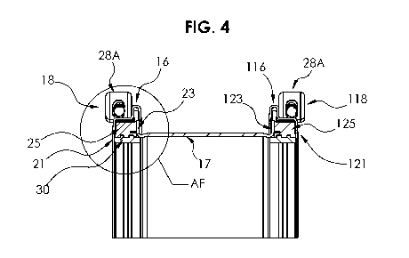
[0012] FIG. 4 is a partial longitudinal cross-sectional view of the
assembly shown in FIG.
2, taken generally on line AE-AE of FIG. 2.
[0013] FIG. 5 is a partial longitudinal cross-sectional view of the
assembly shown in FIG.
4, taken generally within the indicated circle AF of FIG. 4.
[0014] FIG. 6 is a perspective view of the end gasket and end spanner shown
in FIG. 1.
[0015] FIG. 7 is an enlarged perspective view of the end gasket and end
spanner shown in
FIG. 6, taken generally within the indicated circle Al of FIG. 6.
[0016] FIG. 8 is a left end view of the end gasket and end spanner shown in
FIG. 6.
[0017] FIG. 9 is a longitudinal vertical cross-sectional view of the end
gasket and end
spanner shown in FIG. 8, taken generally on line AK-AK of FIG. 8.
[0018] FIG. 10 is an enlarged longitudinal vertical cross-sectional view of
the end gasket
and end spanner shown in FIG. 9, taken generally within the indicated circle
AL of FIG. 9.
[0019] FIG. 11 is a left end view of the end gasket shown in FIG. 6.
[0020] FIG. 12 is a partial longitudinal vertical cross-sectional view of
the end gasket
shown in FIG. 11, taken generally on line AG-AG of FIG. 11.
[0021] FIG. 13 is an enlarged partial longitudinal vertical cross-sectional
view of the end
gasket shown in FIG. 12, taken generally within the indicated circle AH of
FIG. 11.
DETAILED DESCRIPTION OF THE EMBODIMENTS
[0022] At the outset, it should be clearly understood that like reference
numerals are
intended to identify the same structural elements, portions or surfaces
consistently throughout
the several drawing figures, as such elements, portions or surfaces may be
further described
3
CA 03180319 2022-10-14
WO 2021/216681
PCT/US2021/028360
or explained by the entire written specification, of which this detailed
description is an
integral part. Unless otherwise indicated, the drawings are intended to be
read (e.g., cross-
hatching, arrangement of parts, proportion, degree, etc.) together with the
specification, and
are to be considered a portion of the entire written description of this
invention. As used in
the following description, the terms "horizontal", "vertical", "left",
"right", "up" and "down",
as well as adjectival and adverbial derivatives thereof (e.g., "horizontally",
"rightwardly",
"upwardly", etc.), simply refer to the orientation of the illustrated
structure as the particular
drawing figure faces the reader. Similarly, the terms "inwardly" and
"outwardly" generally
refer to the orientation of a surface relative to its axis of elongation, or
axis of rotation, as
appropriate.
[0023]
Referring now to the drawings, and more particularly to FIGS. 1-3 thereof, an
improved pipe coupling assembly is provided, of which a first embodiment is
generally
indicated at 15. As shown, assembly 15 generally comprises middle
encapsulation sleeve or
ring 17 and two end ring gasket assemblies comprising end rings 16 and 116,
end spanners 60
and 160, and end gaskets 25 and 125, respectively, which surround pipe 19.
Middle ring 17,
end rings 16 and 116, end gaskets 25 and 125 and pipe 19 are all generally
ring-like
cylindrical structures orientated about axis x-x. In operation, middle ring 17
and end rings 16
and 116 and end gaskets 25 and 125 are circumferentially disposed on the
outside of pipe 19.
[0024] End
rings 16 and 116 overlap the respective annular flanged edges 23 and 123 of
middle ring 17. End ring 16 includes semi-cylindrical half ring 18A and semi-
cylindrical half
ring 18B, which are bolted together via tightening assembly 18 to encapsulate
pipe 19. Semi-
cylindrical half ring 18A and semi-cylindrical half ring 18B include abutting
ends 27A and
27B and spaced ends 28A and 28B, respectively. Abutting ends 27A and 27B are
configured
to be securely coupled together in a generally gap-free relationship as shown
in FIG. 1. With
abutting ends 27A and 27B coupled via bolt 80 and nut 81, spaced ends 28A and
28B define
a variable gap 29 therebetween. Spaced end 28A of half ring 18A includes a
first bolt lug
projecting radially outwardly from spaced end 28A. Similarly, spaced end 28B
of half ring
18B includes a second bolt lug projecting radially outwardly from spaced end
28B. Half ring
18A and half ring 18B are thereby connected and tightened around pipe 19 via
bolt 80,
extending between openings in the respective lugs, and corresponding nut 81.
Similarly, end
ring 116 includes semi-cylindrical half ring 118A and semi-cylindrical half
ring 118B, which
are bolted together via tightening assembly 118 to encapsulate pipe 19. Half
ring 118A and
half ring 118B are thereby connected and tightened around pipe 19 via bolt 80
and
corresponding nut 81.
4
CA 03180319 2022-10-14
WO 2021/216681
PCT/US2021/028360
[0025] End
gaskets 25 and 125 are configured to wrap around and encircle pipe 19
between the outer surface of pipe 19 and inner pockets 21 and 121 of end rings
16 and 116,
respectively, of assembly 15 to form a seal, with end gaskets 25 and 125
sealing on pipe 19.
Assembly 15 is thereby configured and arranged to be tightened around pipe 19.
[0026] End
gaskets 25 and 125 have specially contoured features and are disposed
generally between the inner annular surfaces of end rings 16 and 116 and end
spanners 60
and 160, the inner cylindrical surfaces of rings 16 and 116 and end spanners
60 and 160, the
outer annular surface of flanges 23 and 123 of middle ring 17, respectively,
and the outer
cylindrical surface of pipe 19. Thus, end gaskets 25 and 125 are sandwiched
between the
inside cylindrical surfaces of end rings 16 and 116 and end spanners 60 and
160 and the
outside cylindrical surface of conduit 19 to provide sufficient sealing force
to prevent leakage
of fluid. Elastic or sealing energy is imparted into assembly 15 by tightening
end rings 16
and 116 from a loosened or a non-actuated position to a tightened sealed
position.
[0027] As shown
in FIGS. 1-7, each of end gaskets 25 and 125 comprises two nested
gasket split-ring layers 30 and 40 that can be separated from each other. Each
end gasket 25
and 125 comprises outer gasket split-ring 40 and removable inner gasket split-
ring 30. Inner
split-ring or layer 30 may be removed from outer split-ring or layer 40.
[0028] As shown
in FIG. 13, outer split ring gasket 40 is a specially-configured ring-
shaped solid penannular member elongated along axis x-x, and is generally
bounded by
rightwardly-facing vertical annular surface 41, inwardly-facing horizontal
cylindrical surface
42, leftwardly-facing vertical annular surface 43, outwardly-facing horizontal
cylindrical arc
surface 44, leftwardly-facing vertical annular arc surface 45, outwardly-
facing horizontal
cylindrical arc surface 46, leftwardly-facing vertical annular arc surface 47,
and outwardly-
facing horizontal cylindrical surface 48, joined at its right marginal end to
the outer marginal
end of surface 41.
[0029] As
shown, surface 41 includes annular pressure assist cavity 56 to aid in sealing
to
pipe 19 under compressive pressure, and surface 42 includes first annular
channel 49A
extending into surface 42 and second annular channel 49B extending into
surface 42.
Surfaces 44, 45, 46 and 47 define end spanner recess 70 in outer annular
surface 43 and outer
cylindrical surface 48 of outer gasket 40, with recess 70 configured to
receive outer leg 61
and middle leg 62 of end spanner 60.
[0030] As shown
in FIG. 7, inner split ring gasket 30 is a specially-configured ring-
shaped solid penannular member elongated along axis x-x and is generally
bounded by
rightwardly-facing vertical annular surface 31, inwardly-facing horizontal
cylindrical surface
CA 03180319 2022-10-14
WO 2021/216681
PCT/US2021/028360
32, leftwardly-facing vertical annular surface 33, and outwardly-facing
horizontal cylindrical
surface 34, joined at its right marginal end to the outer marginal end of
surface 31. As
shown, surface 34 includes first spline 39A extending outwardly from surface
34 and second
spline 39B extending outwardly from surface 34.
[0031] Splines
39A and 39B of inner gasket 30 are orientated in a plane substantially
perpendicular to axis x-x and mate with channels 49A and 49B of outer gasket
40,
respectively. Inner gasket split-ring 30 is manually removable from outer
gasket split-ring 40
to allow end gaskets 25 and 125 to be installed on an oversize pipe. Inner
split-ring 30 and
outer split-ring 40 are loosely connected to each other via annular splines
39A and 39B of
inner gasket 30 being nested in annular channels 49A and 49B, respectively,
such that inner
split-ring 30 is adapted to be removed from outer split-ring 40 at a
predetermined location.
This allows end gaskets 25 and 125 to be used with pipes of substantially
different diameters.
For pipes of greater outer diameter, inner split-ring 30 is manually separated
from outer split-
ring 40 and just outer split-ring 40 is used as the end gasket.
[0032] As
shown, inner gasket layer 30 has an axial width between side surfaces 31 and
33 that is greater than the axial width between side surfaces 41 and 43 of
outer gasket layer
40. As shown, outer split-ring 40 does not entirely overlap inner split-ring
30. Inner split-
ring 30 has outer axial width along axis x-x and outer split ring 40 has outer
axial width
along axis x-x less than the axial width of inner split ring 30.
[0033] Split-
ring end gaskets 25 and 125 are formed of a resilient material and are cut
radially so as to be penannular and not form a full ring. Thus, instead of
being a full
continuous annular ring, a radial break or gap is provided through each layer
30 and 40 at a
circumferential location. Thus, each layer 30 and 40 has a radial split
through the entire
gasket cross-section. The edges of the gap may thereby be manually separated
or pulled apart
from each other to form a more open C-shaped member. Once installed on pipe
19, the
opposed ends of the split-ring gasket layers 30 and 40 will move back towards
each other and
the gap will close up.
[0034] As shown
in FIG. 5, end ring 16 includes cylindrical horizontal center portion 64
with an inner end and an outer end, inwardly-facing U-shaped groove portion 69
(defined by
annular vertical portion 66, cylindrical horizontal portion 64, and annular
vertical portion 66)
extending radially outward from the inner end of center portion 64, and
annular outer portion
65 extending radially inward from the outer end of center portion 64. U-shaped
portion 69 is
configured to axially and radially overlap annular flange 23 of middle ring
17. At least a
portion of gasket 25 is captured axially between outer portion 65 of end ring
16 and flange 23
6
CA 03180319 2022-10-14
WO 2021/216681
PCT/US2021/028360
of middle ring 17. At least a portion of gasket 25 is captured radially
between center portion
64 of end ring 16 and pipe 19. Thus, outer portion 65 of end ring 16, center
portion 64 of end
ring 16, and flange 23 of middle ring 17 collectively define gasket seat 21
for split-ring
gasket 25.
[0035] To
bridge gap 29 that is formed between spaced ends 28A and 28B of end ring 16,
end spanner plate 60, placed in recess 70 on the outside of gasket 25 and
orientated transverse
to axis x-x, is employed to provide gasket compression across gap 29. As shown
in FIG. 10,
end spanner 60 is generally S-shaped in cross section and has an arcuate shape
along its
length 94 and is generally bounded by rightwardly-facing vertical annular arc
surface 82,
inwardly-facing horizontal cylindrical arc surface 83, rightwardly-facing
vertical arc surface
84, inwardly-facing horizontal cylindrical arc end surface 85, leftwardly-
facing vertical
annular arc surface 86, outwardly-facing horizontal cylindrical arc surface
87, leftwardly-
facing vertical annular arc surface 88, and outwardly-facing horizontal
cylindrical arc end
surface 89, joined at its right marginal end to the outer marginal end of
surface 82. Thus,
opposed surfaces 83 and 87 define center arcuate leg 62, surfaces 84, 85 and
86 define
outside arcuate leg 61 extending generally perpendicular to, and radially
inwardly of, center
leg 62 at the outside end of center leg 62, and surfaces 88, 89 and 82 define
inside arcuate leg
63, extending generally perpendicular to, and radially outwardly of, center
leg 62 at the inside
end of center leg 62. Inside leg 63 and outside leg 61 extend in differing
directions from
center leg 62 to form the generally S-shaped cross section of arcuate spanner
plate 60.
Spanner plate 60 fits in recess 70 in the outer surface of elastomeric gasket
25 and is
compressed radially inward by the lugs of spaced ends 28A and 28B of end ring
16.
[0036] When end
spanner 60 is positioned in gap 29 between spaced ends 28A and 28B
of end rings 16 and 116, center leg 62 is positioned radially inward of center
portion 64 of
rings 16 and 116 at spaced ends 28A and 28B, outside leg 61 is positioned
axially inside of
outer portion 65 of rings 16 and 116 at spaced ends 28A and 28B, and inside
leg 63 is
positioned axially inside of, and radially overlaps, annular vertical portion
66 of groove
portion 69 of rings 16 and 116 at spaced ends 28A and 28B. End spanner 60
thereby defines
an arc length 94 that is at least long enough to span gap 29. And end spanner
60 and split end
ring 16 collectively define a closed ring or loop for receiving annular gasket
25. Thus,
spanner 60 is a metallic strip that spans arc-shaped gap 29 between opposed
edges 28A and
28B of end ring 16. The interior edges and surfaces of end ring 16 that are in
contact with
spanner 60 apply a normal force or pressure that is directed radially inward
toward the center
axis of pipe 19, which develops the necessary sealing pressure between spanner
60 and pipe
7
CA 03180319 2022-10-14
WO 2021/216681
PCT/US2021/028360
19. Spanner 60 is designed to compress gasket 25 across gap 29 between
longitudinal edges
28A and 28B of end ring 16. The opposed spaced ends 28A and 28B of end ring 16
are
intended to slide, translate or slip over outer surface 87 of spanner 60, and
thereby provide
diameter reduction and gasket compression upon the tightening of connection
assembly 18.
As nut 81 is tightened on bolt 80 of connection assembly 18, a radially
orientated inward
force is applied to spanner 60 and the opposed lugs of opposed ends 28A and
28B of end ring
16 are drawn together, thereby tightening assembly 15 to pipe 19.
[0037] As shown
in FIGS. 6-13, arcuate recess 70 in gasket layer 40 comprises both axial
recess portion 71 and radial recess portion 72 that are configured to receive
and contain legs
61 and 62 of end spanner 60, respectively. As shown, recess 70 is generally a
L-shaped space
in cross section and has an arcuate shape along its length 77 and is generally
defined by
surfaces 44, 45, 46 and 47 of gasket layer 40 of gasket 25. Thus, surfaces 46
and 47 of gasket
layer 40 define radial recess portion 72 of recess 70 and surfaces 44 and 45
of gasket layer 40
define axial recess portion 71 extending generally perpendicular to, and
radially inwardly of,
radial recess portion 72 at the outside end of radial recess portion 72. As
shown, radial recess
portion 72 has radial depth 74 inward radially from outer cylindrical surface
48 of gasket
layer 40. Axial recess portion 71 has axial depth 73 inward axially from outer
annular
surface 43 of gasket layer 40. Center leg 62 of spanner has radial thickness
91 between
surfaces 83 and 87 and outer leg 61 has axial thickness 90 between surfaces 86
and 84. In
this embodiment, radial thickness 91 of center leg 62 of spanner 60 is
slightly greater than
radial depth 74 of recess 70 of gasket layer 40 and axial thickness 90 of
outer leg 61 of
spanner 60 is equal to axial depth 73 of recess 70 of gasket layer 40.
Abutment between
spanner edge 82 and gasket edge 47 maintains axial alignment and position of
spanner 60 in
gasket layer 40. Such relative depth to thicknesses may be varied as desired.
Preferably, the
depth to thickness ratio 73/90 of axial recess 71 is between about 0.9 and
about 1.1 and the
depth to thickness ratio 74/91 of radial recess 72 is between about 0.5 and
about 0.9. Thus,
the outer sides of gasket layer 40 generally include uniform outer surfaces 43
and 48 and
spanner recess 70 in outer surfaces 43 and 48 is sized to receive spanner 60
such that portions
of spanner 60 may be embedded or nested into gasket 25. In certain
embodiments, such
portions of spanner 60 lie flush with surface 43 and/or 48 of the outer sides
of gasket 25 and
do not project above the outer surfaces of arcuate gasket 25.
[0038] Radial
recess 72 has axial width 76 between annular arc surface 47 and annular
surface 43 of gasket layer 40. Axial width 76 of radial recess 72 may be
adjusted relative to
axial length 92 of center leg 62 to provide the desired clearance between
surfaces 47 and 82
8
CA 03180319 2022-10-14
WO 2021/216681
PCT/US2021/028360
of gasket layer 40 and spanner 60, respectively. Preferably, the width to
length ratio 76/92 of
radial recess 72 is between about 1.01 and about 1.5.
[0039] Axial
recess 71 has radial width 75 between cylindrical arc surface 44 and
cylindrical surface 48 of gasket layer 40. Radial width 75 of axial recess 71
may be adjusted
relative to radial length 93 of outer leg 61 to provide the desired clearance
between surfaces
44 and 85 of gasket layer 40 and spanner 60, respectively. Preferably, the
width to length
ratio 75/93 of axial recess 71 is between about 1.01 and about 1.5.
[0040] Spanner
60 has an arc radius about axis x-x and spanner arc length 94 from its left
edge 95 to its right edge 96 transverse to axis x-x and spanner recess 70 has
corresponding
arc radius and recess arc length 77 from its left edge 78 to its right edge 79
transverse to axis
x-x. Recess arc length 77 of recess 70 may be adjusted relative to spanner arc
length 94 of
spanner 60 to provide the desired clearance between the opposed left
transverse edges 95 and
78 and opposed right transverse edges 96 and 79 of recess 70 of gasket layer
40 and spanner
60, respectively. Preferably, the recess arc length to spanner arc length
ratio 77/94 of recess
70 is between about 1.01 and about 1.5.
[0041] The
aforementioned clearances may be selected to provide desired volumetric
space or clearance for gasket layer 40 to move into as end ring 16 is
tightened to pipe 19 and
gasket 25 is radially compressed between end ring 16 and pipe 19, facilitating
an improved
seal.
[0042] Gasket
recess 70 provides a number of unexpected benefits over the prior art. For
example, and without limitation, gasket recess 70 provides clearance for
gasket 25 and
spanner 60 to fit into the seat 21 of end ring 16, which assists in assembly.
Gasket recess 70
locates and positions spanner 60 so that spanner 60 does not move and is
retained in recess 70
in gasket layer 40 instead of sliding around relative to gasket layer 40.
Gasket recess 70
provides improved control over and uniformity of gasket pressure in the
vicinity and region
of spanner 60. Gasket recess 70 prevents spanner 60 from digging into or
rupturing the outer
rubber gasket surfaces 43 and 48 due to otherwise excessive pressure at
spanner edges 95, 96,
85 and/or 82. Gasket spanner recess 70 depth relative to spanner thickness can
be selected to
control overall gasket compression. Gasket recess 70 helps prevent spanner 60
from
"snagging" on the inner surfaces and coatings of both center portion 64 and
outer portion 65
of end ring 16 so that spanner 60 and end ring 16 will slide freely relative
to each other and
thereby allow for assembly installation and tightening without interference or
snagging.
Gasket recess 70 provides for increased seal pressure and seal reliability at
spanner 60 and
9
CA 03180319 2022-10-14
WO 2021/216681
PCT/US2021/028360
provides an improved circumferential seal when assembly 18 is tightened and
assists in the
progressive seal that occurs near spanner 60 during installation and bolt
tightening.
[0043] End ring
116, end spanner 170, and end gasket 125 are configured and function
substantially the same as end ring 16, spanner 70 and end gasket 25.
[0044] The
present invention contemplates that many changes and modifications may be
made. Therefore, while forms of the improved coupling assembly have been shown
and
described, and a number of alternatives discussed, persons skilled in this art
will readily
appreciate that various additional changes and modifications may be made
without departing
from the scope of the invention, as defined and differentiated by the claims.