Note: Descriptions are shown in the official language in which they were submitted.
CA 03180700 2022-10-20
SUPPORT DEVICE AND WIND GENERATING SET
CROSS-REFERENCE TO RELATED APPLICATIONS
[0001] The present application claims the priority to Chinese Patent
Application No.
202010342220.8, titled "SUPPORT DEVICE AND WIND TURBINE", filed on April 27,
2020, which is incorporated herein by reference in its entirety.
FIELD
[0002] The present application relates to the technical field of wind power,
and in particular
to a support device and a wind turbine.
BACKGROUND
[0003] A converter cabinet, a main control cabinet, a water-cooling cabinet, a
switch cabinet,
a fire hydrant cabinet and other electrical equipment are enclosed in the
tower of the wind
turbine. These equipment need to be placed inside the tower and at a certain
height from the
ground, which, on the one hand, facilitates the cabling of these cabinets, and
on the other hand,
avoids the equipment from being immersed when water enters the tower.
Therefore, the
electrical equipment needs the support device to support.
[0004] In the construction of wind power projects, situation that needs to add
equipment or
needs to change the tower model in the later stage according to the special
circumstances of
the project often occur. Especially for the case of adding equipment in the
later stage, the
support device needs to be retrofitted according to the existing conditions,
for example,
changing the dimension of the support device. Due to the unreasonable
structural design of
the existing support device, it is difficult to retrofit the support device
according to the project
requirements, which adversely affects versatility of the support device.
[0005] Therefore, there is an urgent need for a new support device and a wind
turbine.
- 1 -
Date Regue/Date Received 2022-10-20
CA 03180700 2022-10-20
SUMMARY
[0006] A support device and a wind turbine are provided according to the
embodiments of the
present application. The support device is configured to support electrical
equipment of the
wind turbine, and the dimension and/or load-bearing capacity of the support
device can be
adjusted according to the requirements of the equipment, so the support device
has better
versatility.
[0007] In one aspect, a support device for a wind turbine is provided
according to the
embodiments of the present application. The wind turbine includes electrical
equipment, and
the support device includes a support frame and a support platform. The
support frame has a
hollow frame structure and includes multiple beam members, adjacent beam
members are
connected to each other, and the relative position between at least one group
of two beam
members connected to each other is adjustable. The support platform is
arranged on a surface
of the support frame in a height direction of the support frame and connected
with the beam
members, and the support platform is configured to support the electrical
equipment.
[0008] In an embodiment according to one aspect of the present application,
the support
device further includes a first connecting member, and at least two beam
members intersect
with each other and are connected by the first connecting member, and the
relative position
between the first connecting member and at least one beam member is
adjustable, and the first
connecting member is detachably connected with the at least one beam member.
[0009] In any one of the foregoing embodiments according to one aspect of the
present
application, the beam member defines a first sliding groove, and the first
connecting member
includes a first extension portion and a second extension portion which
intersect with each
other. The first extension portion is snapped in a first sliding groove of one
of the two
intersecting beam members, and the first extension portion is in sliding fit
with the first
sliding groove. The second extension portion is snapped in a first sliding
groove of the other
of the two intersecting beam members, and the second extension portion is in
sliding fit with
the corresponding first sliding groove. The support device further includes a
first fastener, the
first extension portion is provided with the first fastener, and/or, the
second extension portion
is provided with the first fastener, so as to lock the relative position
between the first
connecting member and the corresponding beam member.
- 2 -
Date Regue/Date Received 2022-10-20
CA 03180700 2022-10-20
10010] In any one of the foregoing embodiments according to one aspect of the
present
application, the support device further includes a second connecting member,
at least two
beam members extend in a same direction and are arranged in sequence in the
extension
direction, and the two beam members that extend in the same direction and are
arranged in
sequence in the extension direction are connected to each other by the second
connecting
member, wherein the relative position between the second connecting member and
the at least
one beam member is adjustable and the second connecting member is detachably
connected
with the at least one beam member.
[0011] In any one of the foregoing embodiments according to one aspect of the
present
application, the beam member defines the first sliding groove, the second
connecting member
is of a strip shape and includes a first connecting end and a second
connecting end that are
oppositely arranged, the first connecting end is inserted in the first sliding
groove of one of
the two beam members that extend in the same direction and are arranged in
sequence in the
extension direction and the first connecting end is in sliding fit with the
first sliding groove,
and the second connecting end is inserted in the first sliding groove of the
other of the two
beam members that extend in the same direction and are arranged in sequence in
the extension
direction and the second connecting end is in sliding fit with the
corresponding first sliding
groove. The support device further includes a second fastener, the first
connecting end is
provided with the second fastener, and/or, the second connecting end is
provided with the
second fastener, so as to lock the relative position between the second
connecting member
and the beam member.
[0012] In any one of the foregoing embodiments according to one aspect of the
present
application, the beam member is of a prismatic shape, at least one side wall
surface of the
beam member defines the first sliding groove recessed inwards, and the first
sliding groove
penetrates through the beam member in the extension direction.
[0013] In any one of the foregoing embodiments according to one aspect of the
present
application, the beam member is made of a first material, and the first
material includes at
least one of aluminum alloy, magnesium aluminum alloy, titanium alloy,
aluminum silicon
alloy, aluminum copper alloy, and aluminum zinc alloy.
[0014] In any one of the foregoing embodiments according to one aspect of the
present
application, the beam member has a profile structure and has at least one
cavity inside, and a
- 3 -
Date Regue/Date Received 2022-10-20
CA 03180700 2022-10-20
projection of the side wall defining the cavity in the extension direction of
the beam member
is a polygon or a honeycomb shape.
[0015] In any one of the foregoing embodiments according to one aspect of the
present
application, the support platform includes a body portion and a surrounding
plate arranged
around the body portion, and the surrounding plate is movably connected with
the body
portion, so that the dimension of the outer edge of the support platform is
adjustable.
[0016] In any one of the foregoing embodiments according to one aspect of the
present
application, the body portion includes a support plate and an enclosing part
wrapping the
outer periphery of the support plate. The enclosing part has a horizontal
extension portion and
a vertical installation portion stacked above the horizontal extension portion
in the height
direction. The vertical installation portion defines an adjustment groove, and
the surrounding
plate is inserted into the adjustment groove and is in clearance fit with the
adjustment groove.
In the height direction, at least part of the surrounding plate overlaps with
and is detachably
connected with the body portion.
[0017] In any one of the foregoing embodiments according to one aspect of the
present
application, the surrounding plate includes a pressing portion and an
adjustment portion that
are intersected and connected with each other, the adjustment portion is
arranged around the
body portion, and the adjustment portion is inserted into the adjustment
groove and is
detachably connected with the body portion, and/or, the surrounding plate
includes multiple
arc-shaped units, and the multiple arc-shaped units are sequentially arranged
along the outer
edge of the body portion, and the relative position between each arc-shaped
unit and the body
portion is adjustable.
[0018] In any one of the foregoing embodiments according to one aspect of the
present
application, the beam member at least connected to the support platform, among
the multiple
beam members, further includes a second sliding groove, and the support device
further
includes a third connecting member and a third fastener. The third connecting
member
includes a first snapping end and a second snapping end that are sequentially
arranged. At
least part of the first snapping end extends in the second sliding groove and
engages with the
side wall defining the second sliding groove. The second snapping end abuts
against the
support platform and is detachably connected to the support platform through
the third
fastener.
- 4 -
Date Regue/Date Received 2022-10-20
CA 03180700 2022-10-20
[0019] In any one of the foregoing embodiments according to one aspect of the
present
application, the support device further includes a height adjusting member
which is arranged
on one side of the support frame away from the support platform and connected
to at least
part of the beam members to adjust the height of the support platform.
[0020] In any one of the foregoing embodiments according to one aspect of the
present
application, the support device further includes a flip cover plate, the
support platform defines
at least one notch, and the flip cover plate is movably connected in at least
one notch.
[0021] In any one of the foregoing embodiments according to one aspect of the
present
application, the support device further includes a bridge frame, which is
movably connected
to at least one beam member.
[0022] In any one of the foregoing embodiments according to one aspect of the
present
application, the support device further includes a reinforcing support member
which is
connected between the support frame and the support platform.
[0023] In any one of the foregoing embodiments according to one aspect of the
present
application, the support device further includes an installation port, and the
installation port is
movably connected with at least one beam member.
[0024] In another aspect, a wind turbine is provided according to the
embodiments of the
present application, which includes a tower, the tower includes a tower body
and an
accommodation space defined by the tower body; a support device, the support
device is
arranged in the accommodation space; and electrical equipment, the electrical
equipment is
installed on the support platform of the support device.
[0025] According to the support device and the wind turbine provided by the
embodiments of
the present application, the support device includes the support frame and the
support
platform, the support platform is configured to support and place the
electrical equipment, and
the support frame is configured to support the support platform and the
electrical equipment
thereon at a predetermined height. Besides, since the support frame has a
hollow frame
structure and includes multiple beam members and the relative position between
at least one
group of two beam members connected to each other is adjustable, the dimension
and/or load-
bearing capacity of the support frame is adjustable, that is, the dimension
and/or load-bearing
capacity of the support frame can be adjusted by adjusting the relative
position between the
- 5 -
Date Regue/Date Received 2022-10-20
CA 03180700 2022-10-20
beam members connected to each other according to the project requirements,
thereby
improving the overall versatility of the support device.
BRIEF DESCRIPTION OF THE DRAWINGS
.. [0026] Features, advantages, and technical effects of exemplary embodiments
of the present
application will be described below with reference to the accompanying
drawings.
[0027] Figure 1 is a structural view of part of a wind turbine according to an
embodiment of
the present application;
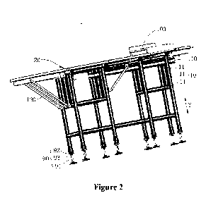
[0028] Figure 2 is a perspective view of a support device according to an
embodiment of the
present application;
[0029] Figure 3 is a front view of the support device according to an
embodiment of the
present application;
[0030] Figure 4 is a top view of the support device according to an embodiment
of the present
application;
[0031] Figure 5 is a schematic structural view of a first connecting member
according to an
embodiment of the present application;
[0032] Figure 6 is a partial enlarged view of the support device according to
an embodiment
of the present application;
[0033] Figure 7 is a schematic structural view of a second connecting member
according to
an embodiment of the present application;
[0034] Figure 8 is a state view of beam members extending in a same direction
and connected
to each other according to an embodiment of the present application;
[0035] Figure 9 is another state view of the beam members extending in the
same direction
and connected to each other according to an embodiment of the present
application;
[0036] Figure 10 is a schematic structural view of the beam member according
to an
embodiment of the present application;
[0037] Figure 11 is a schematic structural view of the beam member according
to another
embodiment of the present application;
- 6 -
Date Regue/Date Received 2022-10-20
CA 03180700 2022-10-20
[0038] Figure 12 is a schematic structural view of the beam member according
to another
embodiment of the present application;
[0039] Figure 13 is a schematic structural view of the beam member according
to another
embodiment of the present application;
[0040] Figure 14 is a schematic structural view of the beam member according
to another
embodiment of the present application;
[0041] Figure 15 is a schematic structural view of the beam member according
to another
embodiment of the present application;
[0042] Figure 16 is a schematic structural view of the beam member according
to another
embodiment of the present application;
[0043] Figure 17 is a schematic structural view of the beam member according
to another
embodiment of the present application;
[0044] Figure 18 is a schematic structural view of the beam member according
to another
embodiment of the present application;
[0045] Figure 19 is a schematic structural view of the beam member according
to another
embodiment of the present application;
[0046] Figure 20 is a schematic structural view of the beam member according
to another
embodiment of the present application;
[0047] Figure 21 is another partial enlarged view of the support device
according to an
embodiment of the present application;
[0048] Figure 22 is a schematic structural view of a third connecting member
according to an
embodiment of the present application;
[0049] Figure 23 is another partial enlarged view of the support device
according to an
embodiment of the present application;
[0050] Figure 24 is another partial enlarged view of the support device
according to an
embodiment of the present application;
[0051] Figure 25 is a top view of the support device according to another
embodiment of the
present application; and
- 7 -
Date Regue/Date Received 2022-10-20
CA 03180700 2022-10-20
[0052] Figure 26 is a partial enlarged view of portion A shown in Figure 25.
[0053] Reference numerals in the drawings:
1 support device; 10 support frame;
11 beam member; 111 first sliding groove;
112 cavity; 113 second sliding groove;
114 third position-limiting protrusion; 20 support platform;
21 body portion; 211 support plate;
212 enclosing part; 212a horizontal extension
portion;
212b vertical installation portion; 212c adjustment groove;
2121 arc-shaped unit; 22 surrounding plate;
221 pressing portion; 222 adjustment portion;
23 notch; 30 first connecting member;
31 first extension portion; 311 first opening;
32 second extension portion; 321 second opening;
33 first position-limiting protrusion; 40 first fastener;
50 second connecting member; 51 first connecting end;
511 third opening; 52 second connecting end;
521 fourth opening; 53 second position-limiting
protrusion;
60 second fastener; 70 third connecting member;
71 first snapping end; 72 second snapping end;
80 third fastener; 90 height adjusting member;
91 adjustment screw rod; 92 connecting block;
93 position-limiting nut; 100 flip cover plate;
110 bridge frame; 120 reinforcing support
member;
130 installation port;
- 8 -
Date Regue/Date Received 2022-10-20
CA 03180700 2022-10-20
2 tower; 2a tower body;
2b accommodation space;
3 electrical equipment; X horizontal extension
direction;
Y height direction; M extension direction.
[0054] In the drawings, same components are denoted by the same reference
numerals. The
drawings are not drawn to actual scale.
DETAILED DESCRIPTION OF THE EMBODIMENTS
[0055] Characteristics and exemplary embodiments of the present application
are described in
detail hereafter. Specific details are provided in the following description
for a thorough
understanding of the present application. It should be obvious to those
skilled in the art that
the present application can be implemented without some of the specific
details. The
description of the exemplary embodiments is only intended to provide a better
understanding
of the present application. In the drawings and the following description, at
least part of well-
known structures and techniques are omitted to avoid unnecessarily obscuring
the present
application. The dimensions of part of the structures may be enlarged for a
clear illustration.
Furthermore, the described features, structures, or characteristics may be
combined in any
suitable manner in one or more embodiments.
[0056] All the orientation words appearing in the following description are
the directions
shown in the drawings and are not intended to limit the specific structures of
the support
device and the wind turbine of the present application. In a description of
the present
application, it should be further noted that, unless otherwise explicitly
specified and defined,
terms such as "installation" and "connection" should be understood in a broad
sense, for
example, the terms may imply a fixed connection, a detachable connection, or
an integral
connection; a direct connection or an indirect connection. For the person
skilled in the art, the
terms in the present application should be explained in the light of specific
situation.
[0057] In order to better understand the present application, the support
device and the wind
turbine according to the embodiments of the present application are described
in detail below
with reference to Figures 1 to 26.
- 9 -
Date Regue/Date Received 2022-10-20
CA 03180700 2022-10-20
[0058] Referring to Figure 1, a wind turbine according to an embodiment of the
present
application includes a tower 2, a support device 1, and electrical equipment
3. The tower 2
includes a tower body 2a and an accommodation space 2b defined by the tower
body 2a. The
support device 1 is arranged in the accommodation space 2b, and the electrical
equipment 3 is
mounted on the support device 1. The electrical equipment 3 is supported at a
certain height
from the ground by the support device 1, which not only facilitates the
cabling of the
electrical equipment 3, but also avoids the electrical equipment 3 from being
immersed when
water enters the tower 2 and further affecting the safety performance of the
wind turbine.
[0059] Optionally, the electrical equipment 3 may be at least one of the
following: a converter
cabinet, a main control cabinet, a water-cooling cabinet, a switch cabinet,
and a fire hydrant
cabinet. The number of electrical equipment 3 may be determined according to
the power
generation requirements of the wind turbine, which is not limited herein.
[0060] In a case that the dimension of the tower 2 or the number or weight of
the electrical
equipment 3 need to be changed, an existing support device cannot adapt to the
above
parameter changes according to the engineering requirements, resulting in poor
versatility of
the support device 1, which adversely affects the power generation efficiency
of the wind
turbine.
[0061] Therefore, a new type of support device 1 is further provided according
to the
embodiments of the present application, which can be produced and sold
separately as an
independent component. Of course, the support device can be used in the wind
turbine
according to the above embodiments and used as a component of the wind
turbine. In order to
better understand the support device 1 according to the embodiments of the
present
application, the support device 1 according to the embodiments of the present
application is
described in detail below with reference to Figures 2 to 26.
[0062] Referring to Figures 2 to 4, a support device 1 is provided according
to the
embodiments of the present application, which includes a support frame 10 and
a support
platform 20. The support frame 10 has a hollow frame structure and includes
multiple beam
members 11, adjacent beam members 11 are connected to each other, and the
relative position
between at least one group of two beam members 11 connected to each other is
adjustable.
The support platform 20 is arranged on a surface of the support frame 10 in a
height direction
- 10 -
Date Regue/Date Received 2022-10-20
CA 03180700 2022-10-20
Y of the support frame and connected with the beam members 11, and the support
platform
20 is configured to support the electrical equipment 3.
[0063] In the support device 1 according to the embodiments of the present
application, the
relative position between at least one group of two beam members 11 connected
to each other
of the support frame 10 is adjustable, so that the dimension and/or load-
bearing capacity of
the support frame 10 can be adjusted by adjusting the relative position
between the beam
members 11 connected to each other, thereby improving the overall versatility
of the support
device 1.
[0064] Optionally, the dimension of the support device 1 can be adjusted by
adjusting the
relative distance between two beam members 11 connected to each other, so that
the support
device 1 can be adapted to different situations, for example, the tower 2 has
a different radial
dimension or the electrical equipment 3 is required to be located further from
the ground.
[0065] Of course, in some embodiments, at least local strength of the support
device 1 can be
adjusted by adjusting the connection position between two beam members 11
connected to
each other, thereby changing the load-bearing capacity of the corresponding
position.
[0066] Optionally, in the support device 1 according to the above embodiments,
the number
of beam members 11 included in the support frame 10 is not limited to specific
numerical
values, and the lengths and extension directions of the multiple beam members
11 may be
different. For example, some of the multiple beam members 11 are arranged
along the height
direction Y of the support frame 20, at least part of the beam members 11 are
arranged along
the horizontal extension direction X of the support platform 10, and the beam
members 11
arranged in the horizontal extension direction X are intersected and connected
with the beam
members 11 arranged in the height direction Y.
[0067] Referring to Figures 5 and 6, as an alternative embodiment, the support
device 1
according to the above embodiments further includes a first connecting member
30, and at
least two beam members 11 are intersected and connected with each other
through the first
connecting member 30. The relative position between the first connecting
member 30 and at
least one beam member 11 is adjustable, and the first connecting member is
detachably
connected with the at least one beam member. By providing the first connecting
member 30,
two beam members 11 intersected and connected with each other may be connected
to each
other through the first connecting member 30, so as to ensure the stability of
the support
- 11 -
Date Regue/Date Received 2022-10-20
CA 03180700 2022-10-20
frame 10. In addition, by limiting that the relative position between the
first connecting
member 30 and at least one beam member 11 is adjustable and the first
connecting member is
detachably connected with the at least one beam member, the position
adjustment between the
two beam members 11 connected to each other and the assembly requirements can
be
facilitated.
[0068] In some optional embodiments, in the support device 1 according to the
above
embodiments, the beam member 11 defines a first sliding groove 111, and the
first connecting
member 30 includes a first extension portion 31 and a second extension portion
32 which
intersect with each other. The first extension portion 31 is snapped in a
first sliding groove
111 of one of the two intersecting beam members 11, and the first extension
portion 31 is in
sliding fit with the first sliding groove. The second extension portion 32 is
snapped in a first
sliding groove of the other of the two intersecting beam members 11, and the
second
extension portion 32 is in sliding fit with the corresponding first sliding
groove. The support
device 1 further includes a first fastener 40, and the first extension portion
31 is provided with
the first fastener 40. Through the above arrangement, the form of the first
connecting member
30 can be simplified, and the connection between the two beam members 11
intersected and
connected with each other can be facilitated. Moreover, when the distance
between the two
intersecting beam members 11 needs to be adjusted, the first extension portion
31 can be
unlocked by screwing the first fastener 40, so that the first extension
portion 31 can move
along the first sliding groove 111 of the beam member 11 cooperating with the
first extension
portion, which in turn drives the beam member 11 connected to the second
extension portion
32 to move, so as to change the connection position between the two
intersecting beam
members 11 and adjust the local strength of the support frame 10.
[0069] Optionally, in the support device 1 according to the embodiments of the
present
application, the first fastener 40 is provided on the second extension portion
32 to lock the
relative position between the first connecting member 30 and the beam member
11. Through
the above arrangement, the two beam members 11 connected to each other can be
more stable
after position adjustment, thereby improving the safety performance of the
support device 1.
[0070] As an alternative embodiment, the first extension portion 31 may be of
a strip
structure, and be provided with a first opening 311 that matches the shape of
the first fastener
and cooperates with the first fastener. Optionally, the second extension
portion 32 may be
- 12 -
Date Regue/Date Received 2022-10-20
CA 03180700 2022-10-20
of a strip structure and be provided with a second opening 321 that matches
the shape of the
first fastener 40 and cooperates with the first fastener, so as to facilitate
the locking and
unlocking requirements of the relative position with the corresponding beam
member 11.
[0071] Optionally, the first extension portion 31 and the second extension
portion 32 may be
perpendicular to each other, which can facilitate the connection and position
adjustment
between the two intersecting beam members 11 and can optimize the overall
strength of the
support device 1.
[0072] Optionally, each of the first extension portion 31 and the second
extension portion 32
may be provided with a first position-limiting protrusion 33, so that the
first extension portion
31 cannot be detached from the first sliding groove 111 in a direction
intersecting with the
extension direction or the length direction of the beam member 11 connected
with the first
extension portion, and the second extension portion 32 cannot be detached in a
direction
intersecting with the extension direction or the length direction of the beam
member 11
connected with the second extension portion.
[0073] In the support device 1 according to the embodiments of the present
application, at
least two beam members 1111 are intersected and connected with each other
through the first
connecting member 30, so that the connection position between the two beam
members 11
can be adjusted by the first connecting member 30. One beam member 11 can be
moved to
any position of the other beam member 11 through the first connecting member
30. For
example, when the support device 1 requires a higher load-bearing capacity at
some positions,
multiple beam members 11 can be moved to these positions, so the beam members
11 at these
positions become denser and the load-bearing capacity here is further
improved. Moreover,
the intersecting beam members 11 are connected in this way, so that when the
support device
1 is applied to a wind turbine, the positions of the beam members 11 can be
adjusted to avoid
other components such as wiring, thus the support device 1 can be used
flexibly.
[0074] Referring to Figures 7 to 10, in some optional embodiments, the support
device 1
according to the embodiments of the present application further includes a
second connecting
member 50, at least two beam members 11 of the multiple beam members 11 of the
support
frame 10 extend in a same direction and are arranged in sequence in the
extension direction,
and the two beam members 11 that extend in the same direction and are arranged
in sequence
in the extension direction are connected to each other by the second
connecting member 50,
- 13 -
Date Regue/Date Received 2022-10-20
CA 03180700 2022-10-20
and, the relative position between the second connecting member 50 and the at
least one beam
member 11 is adjustable and the second connecting member is detachably
connected with the
at least one beam member. Through the above arrangement, the dimension of the
support
device 1 can be adjusted by adjusting the relative distance between two beam
members
connected to each other, so that the support device 1 can be adapted to
different situations, for
example, the tower 2 has a different radial dimension or the electrical
cabinet is required to be
located further from the ground.
[0075] For example, as shown in Figures 7 and 8, two beam members 11 extending
in the
height direction Y and arranged in sequence are connected to each other by the
second
connecting member 50, and the distance between the two beam members 11
extending in the
height direction Y can be increased by adjusting the relative position between
the second
connecting member 50 and one or two of the beam members 11, so that the
overall dimension
of the two beam members 11 and the second connecting member 50 connecting the
two beam
members becomes longer in the height direction Y, which meets the requirement
of adjusting
the overall height of the support device 1.
[0076] Of course, when the height value required to be increased in the height
direction Y is
greater, since the second connecting member 50 is detachably connected to the
beam member
11, the second connecting member 50 may be detached and separated from one of
the beam
members 11, and then another beam member 11 with a predetermined required
length and
another second connecting member 50 may be added between the two beam members
11
extending in the height direction Y, both ends of the additional beam member
11 are
connected to the initial beam members 11 of the support device 1 through the
second
connecting member 50, which can also increase the height of the support device
1 in the
height direction Y.
[0077] That is, when the dimension to be adjusted is in a small degree, the
dimension to be
adjusted can be realized by adjusting the relative position between the second
connecting
member 50 and the beam member 11, that is, by adjusting the dimension of the
second
connecting member 50 extending out of the beam member 11. When the dimension
to be
adjusted is in a large degree, the dimension to be adjusted can be realized by
increasing the
number of the beam members 11 and connecting these newly added beam members to
the
- 14 -
Date Regue/Date Received 2022-10-20
CA 03180700 2022-10-20
initial beam members 11 through the second connecting member 50, thereby
improving the
versatility of the support device 1.
[0078] It is conceivable that, in the above embodiments, the two beam members
11 extending
in the height direction Y are connected by the second connecting member 50. Of
course, in
some other embodiments, the two beam members 11 extending in the horizontal
extension
direction X may be connected by the second connecting member 50, so that the
size of the
support frame 10 in the horizontal extension direction X is adjustable. The
principle is the
same as the above, which will not be repeated again.
[0079] Referring to Figures 7 to 10, as an alternative embodiment, in the
support device 1
.. according to the above embodiments, the beam member 11 defines the first
sliding groove
111, the second connecting member 50 is of a strip shape and includes a first
connecting end
51 and a second connecting end 52 that are oppositely arranged, the first
connecting end 51 is
inserted in the first sliding groove 111 of one of the two beam members 11
that extend in the
same direction and are arranged in sequence in the extension direction and the
first connecting
.. end is in sliding fit with the first sliding groove, and the second
connecting end 52 is inserted
in the first sliding groove 111 of the other of the two beam members 11 that
extend in the
same direction and are arranged in sequence in the extension direction and the
second
connecting end is in sliding fit with the corresponding first sliding groove.
The support device
1 further includes a second fastener 60, the first connecting end 51 is
provided with the
.. second fastener 60, and/or, the second connecting end 52 is provided with
the second fastener
60, so as to lock the relative position between the second connecting member
50 and the beam
member 11. Similarly, through the above arrangement, the form of the second
connecting
member 50 can be simplified, and the connection between the two beam members
11
extending in the same direction and arranged in sequence can be facilitated.
.. [0080] Moreover, when the distance between the two beam members 11
extending in the
same direction and connected to each other needs to be adjusted, the first
connecting end 51
can move along the first sliding groove 111 of the beam member 11 cooperating
with the first
connecting end by screwing the second fastener 60, and the second connecting
end 52 can
move along the first sliding groove 111 of the corresponding beam member 11
cooperating
with the second connecting end, so as to change the distance between the two
beam members
- 15 -
Date Regue/Date Received 2022-10-20
CA 03180700 2022-10-20
11 extending in the same direction. Furthermore, the dimension of the support
frame 10 in the
height direction Y or the horizontal extension direction X can be better
adjusted.
[0081] Optionally, the second connecting member 50 may be of a strip-shaped
structure, the
first connecting end 51 defines a third opening 511 that matches the shape of
the second
fastener 60 and cooperates with the second fastener, and the second connecting
end 52 defines
a fourth opening 521 that matches the shape of the second fastener 60 and
cooperates with the
second fastener, so as to facilitate the locking and unlocking requirements of
the relative
position with the corresponding beam member 11.
[0082] Optionally, the first connecting end 51 and/or the second connecting
end 52 is
provided with a second position-limiting protrusion 53, so that the second
connecting member
50 cannot be detached from the first sliding groove 111 of the beam member 11
in a direction
intersecting with the extension direction or the length direction of the beam
member 11
connected with the second connecting member, thereby guaranteeing the safety
of the support
device 1.
[0083] Referring to Figure 10, in some optional embodiments, in the support
device 1
according to the above embodiments, the beam member 11 is of a prism shape, at
least one
side wall of the beam member 11 defines the first sliding groove 111 recessed
inwards, and
the first sliding groove 111 penetrates through the beam member 11 in the
extension direction
M or the length direction. Through the above arrangement, the disassembly and
assembly of
the first connecting member 30 and the second connecting member 50 can be
facilitated, so
that the first connecting member 30 and the second connecting member 50 can be
inserted or
slide into the first sliding groove 111 of the corresponding beam member 11
along the
extension direction M of the beam member 11 with which the connecting members
cooperate,
which can not only facilitate the overall forming of the support frame 10, but
also facilitate
the adjustment of the dimension and/or load-bearing capacity of the support
frame 10.
[0084] Optionally, one first sliding groove 111 of the beam member 11 may be
provided. Of
course, in some other embodiments, multiple first sliding grooves 111 may be
provided.
Moreover, the number of the first sliding groove 111 on each wall surface of
the beam
member 11 may be one or more, which can be specifically determined based on
the number
of the connected first connecting members 30 and/or the connected second
connecting
members 50, as long as the provided first sliding grooves can meet the
connection
- 16 -
Date Regue/Date Received 2022-10-20
CA 03180700 2022-10-20
requirements and position adjustment requirements of the beam members 11 of
the support
frame 10.
[0085] Since the first sliding groove 111 is formed by recessing the side wall
surface of the
beam member 11 toward the inside of the beam member 11, the first sliding
groove 111 is
through in the extension direction X of the beam member 11 and penetrates
through the side
wall of the beam member 11 to form a socket 115 to facilitate the installation
of the first
connecting member 30 and the second connecting member 50, facilitate the
insertion, locking
and unlocking of the first connecting member 30 by the first fastener 40, and
facilitate the
insertion, locking and unlocking of the second connecting member 50 by the
second fastener
60.
[0086] Furthermore, due to the above-mentioned structural form of the first
sliding groove,
there is no need to connect the beam members 11 by welding, which can reduce
pollution and
prevent the beam members 11 from deformation by welding, and further guarantee
the
supporting strength of the support device 1.
[0087] Optionally, in order to restrict the first connecting member 30 and the
second
connecting member 50 from separating from the beam member 11 with which the
connecting
members cooperate in a direction intersecting with the extension direction X
of the beam
member 11, a side wall surface of the beam member 11 may be provided with a
third
position-limiting protrusion 114 extending into the socket 115 formed by the
first sliding
groove 111. The first connecting member 30 and the second connecting member 50
can be
prevented from detaching in a direction intersecting with the extension
direction of the beam
member 11 through the cooperation of the third position-limiting protrusion
114 and the first
connecting member 30 and the second connecting member 50.
[0088] Optionally, in a case that the first connecting member 30 includes the
first position-
limiting protrusion 33, the third position-limiting protrusion 114 may be
configured to
cooperate with the first position-limiting protrusion 33, so as to restrict
the first connecting
member 30 from detaching from the beam member 11 as a whole in a direction
intersecting
with the extension direction of the beam member 11 where the first connecting
member is
located. Similarly, in a case that the second connecting member 50 includes
the second
position-limiting protrusion 53, the third position-limiting protrusion 114
may be configured
to cooperate with the second position-limiting protrusion 53, so as to
restrict the second
- 17 -
Date Regue/Date Received 2022-10-20
CA 03180700 2022-10-20
connecting member 50 from detaching from the beam member 11 as a whole in a
direction
intersecting with the extension direction of the beam member 11 where the
second connecting
member is located.
[0089] As an alternative embodiment, in the support device 1 according to the
above
embodiments, the beam member 11 is made of a first material, and the first
material includes
at least one of aluminum alloy, magnesium aluminum alloy, titanium alloy,
aluminum silicon
alloy, aluminum copper alloy, and aluminum zinc alloy. Through the above
arrangement, the
weight of the support device 1 can be further reduced, making the support
device light and
easy to install. The forming efficiency of the support device 1 is effectively
improved.
Moreover, since the beam member 11 is made of the above-mentioned materials,
the oxide
film formed by the beam member 11 itself can still ensure good anti-corrosion
performance,
and there is no need to perform anti-corrosion treatment. The beam member is
suitable for use
in various harsh climate environments, and has no pollution to the
environment, and meets the
requirements of environmental protection policies.
[0090] In some optional embodiments, in the support device 1 according to the
above
embodiments, the beam member 11 has a profile structure, which is low in cost
and easy to
form, and more importantly, realizes generalization and standardization. After
the structure is
determined, the beam member can be designed as a versatile structure and can
be mass-
produced. The structure of the beam member 11 will not change due to the
change of the
diameter of the tower 2, which is beneficial to production and will not cause
material waste.
[0091] As an optional embodiment, in the support device 1 according to the
above
embodiments, the beam member 11 has at least one cavity 112 inside, the weight
of the
support device 1 can be further ensured by providing the cavity 112 inside the
beam member
11 on the basis of guaranteeing the overall strength of the formed support
device 1, and the
-- cost can be saved.
[0092] Optionally, a projection of the side wall defining the cavity 112 in
the extension
direction of the beam member 11 is like a polygon, for example, a regular
quadrilateral such
as a rhombus and the like, which apparently is an optional way. The projection
is not limited
to the above shape, and the shape is applicable as long as the strength of the
beam member 11
-- can be guaranteed.
- 18 -
Date Regue/Date Received 2022-10-20
CA 03180700 2022-10-20
[0093] Referring to Figures 11 to 20, in some embodiments such as the
embodiments shown
in Figures 12 and 13, in a case that the projection of the sidewall defining
the cavity 112 in
the extension direction of the beam member 11 is quadrilateral, the projection
may be a
rectangular shape. Of course, in some embodiments, as shown in Figures 14 to
20, the
projection of the sidewall defining the cavity 112 in the extension direction
of the beam
member 11 may be an irregular polygon, for example, an irregular polygon.
Moreover, in
some embodiments, the projection of the sidewall defining the cavity 112 in
the extension
direction of the beam member 11 may be a honeycomb shape as shown in Figure
20.
[0094] Moreover, as an optional embodiment, in the support device 1 according
to the above
embodiments, the number of cavity 112 of each beam member 11 may be one or
more. In a
case that multiple cavities are provided, shapes of these cavities 112 may be
the same or
different. For example, some cavities 112 may be of a regular-polygon shape,
some cavities
112 may be of an irregular-polygon shape, and some cavities 112 may be of a
honeycomb
shape, as long as the strength requirements of the beam member 11 and the
requirements of
reducing weight and cost can be met.
[0095] Referring to Figures 11 to 22, as an alternative embodiment, in the
support platform
according to the above embodiments, at least the beam member 11 connected to
the
support platform 20 among the multiple beam members 11 further includes a
second sliding
groove 113, and the support device 1 further includes a third connecting
member 70 and a
20 third fastener 80. The third connecting member 70 includes a first snapping
end 71 and a
second snapping end 72 that are sequentially arranged. At least part of the
first snapping end
71 extends in the second sliding groove 113 and engages with the side wall
defining the
second sliding groove 113. The second snapping end 72 abuts against the
support platform 20
and is detachably connected to the support platform 20 through the third
fastener 80. Through
the above arrangement, the requirements of connection strength between the
support platform
20 and the support frame 10 can be guaranteed, and the second snapping end 72
abuts against
the support platform 20 and is detachably connected to the support platform 20
through the
third fastener 80, which facilitates the disassembly and assembly between the
support
platform 20 and the support frame 10 and facilitates the transportation of the
support device 1.
-- [0096] Optionally, in a case that the beam member 11 includes the second
sliding groove 113,
the number of the second sliding groove 113 of the beam member may be one or
more, such
- 19 -
Date Regue/Date Received 2022-10-20
CA 03180700 2022-10-20
as two. Two second sliding grooves 113 may be symmetrically arranged, the
extension
direction of the first sliding groove 111 of a beam member 11 may be the same
as the
extension direction of the second sliding groove 113 of the same beam member
11, and each
first sliding groove 111 of the same beam member 11 may be arranged between
the two
second sliding grooves 113. Each second sliding groove 113 is provided with at
least one
third connecting member 70 connected to the support platform 20. Through the
above
arrangement, the connection strength between the support frame 10 and the
support platform
20 is improved.
[0097] As an alternative embodiment, as shown in Figures 21 and 22, the first
snapping end
71 of the third connecting member 70 may be of a U-shaped plate structure, and
the second
snapping end 72 may be of a flat plate structure. A side wall of the first
snapping end 71 may
extend into the second sliding groove 113 and engage with the second sliding
groove 113, and
the second snapping end 72 may be attached to a body portion 21 and be
detachably
connected to the body portion through the third fastener 80.
[0098] Optionally, in the above embodiments, the first fastener 40, the second
fastener 60,
and the third fastener 80 may be bolts, screws, jackscrews, and the like.
[0099] Referring to Figures 2 to 4, Figure 23 and Figure 24, in some optional
embodiments,
in the support device 1 according to the above embodiments, the support
platform 20 may
include a body portion 21 and a surrounding plate 22 arranged around the body
portion 21,
and the surrounding plate 22 is movably connected with the body portion 21, so
that the
dimension of the outer edge of the support platform 20 is adjustable. Through
the above
arrangement, the support device 1 can better adapt to the dimension change of
the tower 2 of
the wind turbine, so that the overall dimension of the outer edge of the
support platform 20
can be adjusted according to the dimension of the tower 2, and the outer edge
of the support
platform 20 can abut against the inner wall of the tower body 2a of the tower
2 or the gap
between the outer edge of the support platform and the inner wall of the tower
body 2a is kept
within a required range, thereby meeting the support requirements of the
electrical equipment
3.
[0100] In some optional embodiments, in the support device 1 according to the
above
.. embodiments, the body portion 21 includes a support plate 211 and an
enclosing part 212
wrapping the outer periphery of the support plate 211. The enclosing part 212
has a horizontal
- 20 -
Date Regue/Date Received 2022-10-20
CA 03180700 2022-10-20
extension portion 212a and a vertical installation portion 212b stacked above
the horizontal
extension portion 212a in the height direction Y. The vertical installation
portion 212b defines
an adjustment groove 212c, and the surrounding plate 22 is inserted into the
adjustment
groove 212c and is in clearance fit with the adjustment groove 212c. In the
height direction Y,
at least part of the surrounding plate 22 overlaps with and is detachably
connected with the
body portion 21.
[0101] Through the above arrangement, the structure of the body portion 21 can
be simplified,
and the connection between the body portion 21 and the surrounding plate 22
and the
adjustment of the relative position between the body portion and the
surrounding plate can be
facilitated. The surrounding plate 22 can slide along the adjustment groove
212c on the
vertical installation portion 212b to adjust the overall dimension of the
outer edge of the
support platform 20, that is, to adjust the overall dimension of the support
platform 20 in the
radial direction of the tower 2, so that the support device can better adapt
to the tower 2 with
different radial dimensions. Besides, the problem of interference between the
support device 1
and the tower 2 during assembly due to errors during processing and
manufacturing can be
avoided, so that the support device 1 has better versatility and adaptability.
[0102] As an optional embodiment, in the height direction Y, at least part of
the surrounding
plate 22 overlaps with the body portion 21, and the relative position between
the overlapped
portions can be locked by screw rods, positioning pins and other fasteners.
[0103] In some optional embodiments, in the support device 1 according to the
above
embodiments, the surrounding plate 22 includes a pressing portion 221 and an
adjustment
portion 222 that are intersected and connected with each other, the adjustment
portion 222 is
arranged around the body portion 21, and the adjustment portion 222 is
inserted into the
adjustment groove 212c and is detachably connected with the body portion 21.
The above
structural form of the surrounding plate 22 can meet the requirements of
adjusting the relative
position between the surrounding plate and the body portion 21, and can ensure
that the
pressing portion 221 better abuts against the inner wall of the tower body of
the tower 2 to
meet the ensure the safety support requirements of the support device 1 for
the electrical
equipment 3.
[0104] Optionally, the pressing portion 221 and the adjustment portion 222 may
both be of a
plate-like structure, which can reduce the weight of the surrounding plate 22
and reduce the
-21 -
Date Regue/Date Received 2022-10-20
CA 03180700 2022-10-20
cost. Optionally, the pressing portion 221 and the adjustment portion 222 may
be
perpendicular to each other, which can ensure the reliability of the
coordination between the
surrounding plate 22 and the tower 2.
[0105] As an optional embodiment, in the support device 1 according to the
above
embodiments, the surrounding plate 22 includes multiple arc-shaped units 2121,
and the
multiple arc-shaped units 2121 are sequentially arranged along the outer edge
of the body
portion 21, and the relative position between each arc-shaped unit 2121 and
the body portion
21 is adjustable. Through the above arrangement, the connection and position
adjustment
between the surrounding plate 22 and the body portion 21 can be facilitated,
and the smooth
movement of the body portion 21 relative to the surrounding plate 22 can be
ensured to adjust
the overall dimension of the outer edge of the support platform 20.
Optionally, each arc-
shaped unit 2121 is inserted into the adjustment groove 212c and is slidably
connected to the
adjustment groove 212c, and the relative position between each arc-shaped unit
2121 and the
body portion 21 can be locked by screw rods, positioning pins and other
fasteners.
[0106] Referring to Figures 25 and 26, as an optional embodiment, the support
device 1
according to the above embodiments of the present application further includes
an installation
port 130, and the installation port 130 is movably connected with at least one
beam member
11. By providing the installation port 130, the installation of the electrical
equipment 3 can be
facilitated, and the installation port 130 is movably connected to the
corresponding beam
member 11, so that the installation port 130 can be adjusted according to the
position setting
requirements of the electrical equipment 3 to ensure the connection
requirements of the
electrical equipment 3 and the support device 1.
[0107] In some optional embodiments, a notch 23 is provided on the support
plate 211, and
multiple notches 23 may be provided. The beam members 11 connected to the
support
platform 20 can be exposed on the surface of the support platform 20 away from
the support
frame 10 through some of the notches 23. In some optional embodiments, the
installation port
130 may be connected through the second connecting member to where the beam
members 11
are exposed at the support platform 20, so as to better meet the requirements
of adjusting
position between the installation port 130 and the corresponding beam member
11, and
further meet the installation and connection requirements of the electrical
equipment 3.
- 22 -
Date Regue/Date Received 2022-10-20
CA 03180700 2022-10-20
[0108] Referring to Figures 2 to 26, in some optional embodiments, the support
device 1
according to the above embodiments further includes a height adjusting member
90 which is
arranged on one side of the support frame 10 away from the support platform 20
and
connected to at least part of the beam members 11 to adjust the height of the
support platform
20. Through the above arrangement, the versatility of the support device 1 can
be further
improved, so the support device can meet support requirements of the
electrical equipment 3
at different heights.
[0109] Optionally, the height adjusting member 90 is telescopic in the height
direction Y.
Optionally, the height adjusting member 90 is a telescopic cylinder. In some
optional
embodiments, the height adjusting member 90 includes an adjustment screw rod
91 and a
connecting block 92. The connecting block 92 may be connected to the beam
member 11
arranged along the height direction Y. The connecting block 92 is supported on
the
adjustment screw rod 91 through a position-limiting nut 93. By adjusting the
position of the
position-limiting nut 93 on the adjustment screw rod 91, the position
adjustment requirement
of the connecting block 92 on the adjustment screw rod 91 can be met to adjust
the overall
height of the support device 1.
[0110] As an optional embodiment, the support device 1 further includes a flip
cover plate
100, and the flip cover plate 100 is movably connected in at least one notch
23. By providing
the openable flip cover plate 100, it is convenient for the operator to pass.
[0111] In some optional embodiments, the support device 1 according to the
above
embodiments further includes a bridge frame 110, which is movably connected to
at least one
beam member 11. The bridge frame 110 is configured to place the wiring of the
electrical
equipment 3 to ensure the safety of the wiring. Moreover, the bridge frame 110
is movably
connected to at least one beam member 11, so that the position of the beam
member 11 on the
.. support frame 10 can be adjusted according to the wiring requirements, and
the versatility of
the support device 1 can further be improved.
[0112] The optional bridge frame 110 may cooperate with the first sliding
groove 111 of the
corresponding beam member 11 through the first connecting member 30 or the
second
connecting member 50, so as to better realize the movable connection with the
beam member
11 and ensure wiring requirements and/or avoidance requirements for other
components.
- 23 -
Date Regue/Date Received 2022-10-20
CA 03180700 2022-10-20
[0113] In some optional embodiments, the support device 1 according to the
above
embodiments further includes a reinforcing support member 120, which is
connected between
the support frame 10 and the support platform 20. By providing the reinforcing
support
member 120, the connection strength between the support frame 10 and the
support platform
20 can be further improved.
[0114] Optionally, the reinforcing support member 120 may be an oblique
support, and the
reinforcing support member 120 may be hinged to the support frame 10 and the
support
platform 20 respectively, which can ensure the requirement for strengthening
the connection
strength and facilitate the installation of the reinforcing support member
120.
.. [0115] Therefore, according to the support device 1 provided by the
embodiments of the
present application, the support device includes the support frame 10 and the
support platform
20, the support platform 20 is configured to support and place the electrical
equipment 3, and
the support frame 10 is configured to support the support platform 20 and the
electrical
equipment 3 thereon at a predetermined height. Besides, since the support
frame 10 has a
hollow frame structure and includes multiple beam members 11 and the relative
position
between at least one group of two beam members 11 connected to each other is
adjustable, the
dimension and/or load-bearing capacity of the support frame 10 is adjustable,
that is, the
dimension and/or load-bearing capacity of the support frame 10 can be adjusted
by adjusting
the relative position between the beam members 11 connected to each other
according to the
project requirements, thereby improving the overall versatility of the support
device 1.
Therefore, the support device 1 can be widely used in the towers 2 of
different types of wind
turbines and support the electrical equipment 3.
[0116] Since the wind turbine includes the support device 1 provided by the
above
embodiments, which can support the electrical equipment 3 to a predetermined
height, the
wind turbine provided by the embodiments of the present application can adapt
to
requirements of number increase, position change or height change from the
ground of the
electrical equipment 3 through the support device 1, which can ensure the
safety performance
of the electrical equipment 3 and allow the wind turbine to have higher power
generation
efficiency.
[0117] Although the present application has been described with reference to
the preferred
embodiments, various improvements can be made to it and the components therein
can be
- 24 -
Date Regue/Date Received 2022-10-20
CA 03180700 2022-10-20
replaced with equivalents, without departing from the scope of the present
application. In
particular, as long as there is no structural conflict, the various technical
features mentioned in
the various embodiments can be combined in any manner. The present application
is not
limited to the specific embodiments disclosed herein, but includes all
technical solutions
falling within the scope of the claims.
- 25 -
Date Regue/Date Received 2022-10-20