Note: Descriptions are shown in the official language in which they were submitted.
CA 03181332 2022-10-25
WO 2021/222022
PCT/US2021/028857
SYSTEM AND METHOD FOR A MULTI-PRIMARY WIDE GAMUT COLOR
SYSTEM
CROSS REFERENCES TO RELATED APPLICATIONS
[0001] This application relates to and claims priority from the following
applications.
This application claims priority from U.S. Application No. 16/860,769, filed
April 28, 2020,
U.S. Application No. 16/887,807, filed May 29, 2020, U.S. Application No.
17/009,408, filed
September 1, 2020, U.S. Application No. 17/060,959, filed October 1, 2020, and
U.S.
Application No. 17/180,441, filed February 19, 2021, each of which is
incorporated herein by
reference.
[0002] U.S. Application No. 16/860,769 is a continuation-in-part of U.S.
Application No.
16/853,203, filed April 20, 2020, which is a continuation-in-part of U.S.
Patent Application
No. 16/831,157, filed March 26, 2020, which is a continuation of U.S. Patent
Application No.
16/659,307, filed October 21, 2019, now U.S. Patent No. 10,607,527, which is
related to and
claims priority from U.S. Provisional Patent Application No. 62/876,878, filed
July 22, 2019,
U.S. Provisional Patent Application No. 62/847,630, filed May 14, 2019, U.S.
Provisional
Patent Application No. 62/805,705, filed February 14, 2019, and U.S.
Provisional Patent
Application No. 62/750,673, filed October 25, 2018, each of which is
incorporated herein by
reference in its entirety.
[0003] U.S. Application No. 16/887,807 is a continuation-in-part of U.S.
Application No.
16/860,769, filed April 28, 2020, which is a continuation-in-part of U.S.
Application No.
16/853,203, filed April 20, 2020, which is a continuation-in-part of U.S.
Patent Application
No. 16/831,157, filed March 26, 2020, which is a continuation of U.S. Patent
Application No.
16/659,307, filed October 21, 2019, now U.S. Patent No. 10,607,527, which is
related to and
claims priority from U.S. Provisional Patent Application No. 62/876,878, filed
July 22, 2019,
U.S. Provisional Patent Application No. 62/847,630, filed May 14, 2019, U.S.
Provisional
Patent Application No. 62/805,705, filed February 14, 2019, and U.S.
Provisional Patent
1
CA 03181332 2022-10-25
WO 2021/222022
PCT/US2021/028857
Application No. 62/750,673, filed October 25, 2018, each of which is
incorporated herein by
reference in its entirety.
[0004] U. S . Application No. 17/009,408 is a continuation-in-part of U.S.
Application No.
16/887,807, filed May 29, 2020, which is a continuation-in-part of U.S.
Application No.
16/860,769, filed April 28, 2020, which is a continuation-in-part of U.S.
Application No.
16/853,203, filed April 20, 2020, which is a continuation-in-part of U.S.
Patent Application
No. 16/831,157, filed March 26, 2020, which is a continuation of U.S. Patent
Application No.
16/659,307, filed October 21, 2019, now U.S. Patent No. 10,607,527, which is
related to and
claims priority from U.S. Provisional Patent Application No. 62/876,878, filed
July 22, 2019,
U.S. Provisional Patent Application No. 62/847,630, filed May 14, 2019, U.S.
Provisional
Patent Application No. 62/805,705, filed February 14, 2019, and U.S.
Provisional Patent
Application No. 62/750,673, filed October 25, 2018, each of which is
incorporated herein by
reference in its entirety.
[0005] U. S . Application No. 17/060,959 is a continuation-in-part of U.S.
Application No.
17/009,408, filed September 1, 2020, which is a continuation-in-part of U.S.
Application No.
16/887,807, filed May 29, 2020, which is a continuation-in-part of U.S.
Application No.
16/860,769, filed April 28, 2020, which is a continuation-in-part of U.S.
Application No.
16/853,203, filed April 20, 2020, which is a continuation-in-part of U.S.
Patent Application
No. 16/831,157, filed March 26, 2020, which is a continuation of U.S. Patent
Application No.
16/659,307, filed October 21, 2019, now U.S. Patent No. 10,607,527, which is
related to and
claims priority from U.S. Provisional Patent Application No. 62/876,878, filed
July 22, 2019,
U.S. Provisional Patent Application No. 62/847,630, filed May 14, 2019, U.S.
Provisional
Patent Application No. 62/805,705, filed February 14, 2019, and U.S.
Provisional Patent
Application No. 62/750,673, filed October 25, 2018, each of which is
incorporated herein by
reference in its entirety.
2
CA 03181332 2022-10-25
WO 2021/222022
PCT/US2021/028857
[0006] U. S . Application No. 17/180,441 is a continuation-in-part of U.S.
Application No.
17/009,408, filed September 1, 2020, which is a continuation-in-part of U.S.
Application No.
16/887,807, filed May 29, 2020, which is a continuation-in-part of U.S.
Application No.
16/860,769, filed April 28, 2020, which is a continuation-in-part of U.S.
Application No.
16/853,203, filed April 20, 2020, which is a continuation-in-part of U.S.
Patent Application
No. 16/831,157, filed March 26, 2020, which is a continuation of U.S. Patent
Application No.
16/659,307, filed October 21, 2019, now U.S. Patent No. 10,607,527, which is
related to and
claims priority from U.S. Provisional Patent Application No. 62/876,878, filed
July 22, 2019,
U.S. Provisional Patent Application No. 62/847,630, filed May 14, 2019, U.S.
Provisional
Patent Application No. 62/805,705, filed February 14, 2019, and U.S.
Provisional Patent
Application No. 62/750,673, filed October 25, 2018, each of which is
incorporated herein by
reference in its entirety.
BACKGROUND OF THE INVENTION
[0007] 1. Field of the Invention
[0008] The present invention relates to color systems, and more
specifically to a wide
gamut color system with an increased number of primary colors.
[0009] 2. Description of the Prior Art
[0010] It is generally known in the prior art to provide for an increased
color gamut
system within a display.
[0011] Prior art patent documents include the following:
[0012] U. S . Patent No. 10,222,263 for RGB value calculation device by
inventor
Yasuyuki Shigezane, filed February 6, 2017 and issued March 5, 2019, is
directed to a
microcomputer that equally divides the circumference of an RGB circle into 6xn
(n is an
integer of 1 or more) parts, and calculates an RGB value of each divided
color. (255, 0, 0) is
stored as a reference RGB value of a reference color in a ROM in the
microcomputer. The
3
CA 03181332 2022-10-25
WO 2021/222022
PCT/US2021/028857
microcomputer converts the reference RGB value depending on an angular
difference of the
RGB circle between a designated color whose RGB value is to be found and the
reference
color, and assumes the converted RGB value as an RGB value of the designated
color.
[0013] U. S . Patent No. 9,373,305 for Semiconductor device, image
processing system
and program by inventor Hiorfumi Kawaguchi, filed May 29, 2015 and issued June
21, 2016,
is directed to an image process device including a display panel operable to
provide an input
interface for receiving an input of an adjustment value of at least a part of
color attributes of
each vertex of n axes (n is an integer equal to or greater than 3) serving as
adjustment axes in
an RGB color space, and an adjustment data generation unit operable to
calculate the degree
of influence indicative of a following index of each of the n-axis vertices,
for each of the n
axes, on a basis of distance between each of the n-axis vertices and a target
point which is an
arbitrary lattice point in the RGB color space, and operable to calculate
adjusted coordinates
of the target point in the RGB color space.
[0014] U. S . Publication No. 20130278993 for Color-mixing bi-primary color
systems for
displays by inventor Heikenfeld, et.al, filed September 1, 2011 and published
October 24,
2013, is directed to a display pixel. The pixel includes first and second
substrates arranged to
define a channel. A fluid is located within the channel and includes a first
colorant and a
second colorant. The first colorant has a first charge and a color. The second
colorant has a
second charge that is opposite in polarity to the first charge and a color
that is complimentary
to the color of the first colorant. A first electrode, with a voltage source,
is operably coupled
to the fluid and configured to moving one or both of the first and second
colorants within the
fluid and alter at least one spectral property of the pixel.
[0015] U. S . Patent No. 8,599,226 for Device and method of data conversion
for wide
gamut displays by inventor Ben-Chorin, et. al, filed February 13, 2012 and
issued December
3, 2013, is directed to a method and system for converting color image data
from a, for
4
CA 03181332 2022-10-25
WO 2021/222022
PCT/US2021/028857
example, three-dimensional color space format to a format usable by an n-
primary display,
wherein n is greater than or equal to 3. The system may define a two-
dimensional sub-space
having a plurality of two-dimensional positions, each position representing a
set of n primary
color values and a third, scaleable coordinate value for generating an n-
primary display input
signal. Furthermore, the system may receive a three-dimensional color space
input signal
including out-of range pixel data not reproducible by a three-primary additive
display, and
may convert the data to side gamut color image pixel data suitable for driving
the wide gamut
color display.
[0016] U. S . Patent No. 8,081,835 for Multiprimary color sub-pixel
rendering with
metameric filtering by inventor Elliot, et. al, filed July 13, 2010 and issued
December 20,
2011, is directed to systems and methods of rendering image data to
multiprimary displays
that adjusts image data across metamers as herein disclosed. The metamer
filtering may be
based upon input image content and may optimize sub-pixel values to improve
image
rendering accuracy or perception. The optimizations may be made according to
many
possible desired effects. One embodiment comprises a display system
comprising: a display,
said display capable of selecting from a set of image data values, said set
comprising at least
one metamer; an input image data unit; a spatial frequency detection unit,
said spatial
frequency detection unit extracting a spatial frequency characteristic from
said input image
data; and a selection unit, said unit selecting image data from said metamer
according to said
spatial frequency characteristic.
[0017] U. S . Patent No. 7,916,939 for High brightness wide gamut display
by inventor
Roth, et. al, filed November 30, 2009 and issued March 29, 2011, is directed
to a device to
produce a color image, the device including a color filtering arrangement to
produce at least
four colors, each color produced by a filter on a color filtering mechanism
having a relative
segment size, wherein the relative segment sizes of at least two of the
primary colors differ.
CA 03181332 2022-10-25
WO 2021/222022
PCT/US2021/028857
[0018] U. S . Patent No. 6,769,772 for Six color display apparatus having
increased color
gamut by inventor Roddy, et. al, filed October 11, 2002 and issued August 3,
2004, is
directed to a display system for digital color images using six color light
sources or two or
more multicolor LED arrays or OLEDs to provide an expanded color gamut.
Apparatus uses
two or more spatial light modulators, which may be cycled between two or more
color light
sources or LED arrays to provide a six-color display output. Pairing of
modulated colors
using relative luminance helps to minimize flicker effects.
SUMMARY OF THE INVENTION
[0019] It is an object of this invention to provide an enhancement to the
current RGB
systems or a replacement for them.
[0020] In one embodiment, the present invention provides system for
displaying a
primary color system including a set of image data, an image data converter, a
set of Session
Description Protocol (SDP) parameters, and at least one display device,
wherein the set of
image data includes primary color data for at least four primary color values,
wherein the at
least one display device and the image data converter are in network
communication, and
wherein the image data converter is operable to convert the set of image data
for display on
the at least one display device.
[0021] In another embodiment, the present invention provides a system for
displaying a
primary color system including a set of image data, an image data converter,
wherein the
image data converter includes a digital interface, wherein the digital
interface is operable to
encode and decode the set of image data, a set of Session Description Protocol
(SDP)
parameters, and at least one display device, wherein the set of image data
further includes
primary color data for at least four primary color values, wherein the at
least four primary
color values include a cyan primary, wherein the at least one display device
and the image
6
CA 03181332 2022-10-25
WO 2021/222022
PCT/US2021/028857
data converter are in network communication, and wherein the image data
converter is
operable to convert the set of image data for display on the at least one
display device.
[0022] In yet another embodiment, the present invention provides a system
for displaying
a primary color system including a set of image data, an image data converter,
wherein the
image data converter includes a digital interface, wherein the digital
interface is operable to
encode and decode the set of image data, a set of Session Description Protocol
(SDP)
parameters, and at least one display device, wherein the set of image data
further includes
primary color data for at least four primary color values, wherein the at
least four primary
color values include at least one white emitter, wherein the at least one
display device and the
image data converter are in network communication, and wherein the image data
converter is
operable to convert the set of image data for display on the at least one
display device.
[0023] In still another embodiment, the present invention provides a method
for
displaying a multi-primary color system including providing a set of image
data, encoding the
set of image data using a digital interface of an image data converter,
wherein the image data
converter is in network communication with at least one display device,
decoding the set of
image data using the digital interface of the image data converter, and
converting the set of
image data for display on the at least one display device.
[0024] These and other aspects of the present invention will become
apparent to those
skilled in the art after a reading of the following description of the
preferred embodiment
when considered with the drawings, as they support the claimed invention.
BRIEF DESCRIPTION OF THE DRAWINGS
[0025] The patent or application file contains at least one drawing
executed in color.
Copies of this patent or patent application publication with color drawing(s)
will be provided
by the Office upon request and payment of the necessary fee.
7
CA 03181332 2022-10-25
WO 2021/222022
PCT/US2021/028857
[0026] FIG. 1 illustrates one embodiment of a four primary system including
a red
primary, a green primary, a cyan primary, and a blue primary.
[0027] FIG. 2 illustrates one embodiment of a four primary system including
a red
primary, a first green primary, a second green primary, and a blue primary.
[0028] FIG. 3 illustrates another embodiment of a four primary system
including a red
primary, a first green primary, a second green primary, and a blue primary.
[0029] FIG. 4 illustrates one embodiment of a five primary system including
a red
primary, a green primary, a cyan primary, a blue primary, and a white emitter.
[0030] FIG. 5 illustrates one embodiment of a five primary system including
a red
primary, a first green primary, a second green primary, a blue primary, and a
white emitter.
[0031] FIG. 6 illustrates another embodiment of a five primary system
including a red
primary, a first green primary, a second green primary, a blue primary, and a
white emitter.
[0032] FIG. 7 illustrates another embodiment of a five primary system
including a red
primary, a first green primary, a second green primary, a blue primary, and a
white emitter.
[0033] FIG. 8 illustrates one embodiment of a six primary system including
a red
primary, a green primary, a blue primary, a cyan primary, a magenta primary,
and a yellow
primary ("6P-B") compared to ITU-R BT.709-6.
[0034] FIG. 9 illustrates another embodiment of a six primary system
including a red
primary, a green primary, a blue primary, a cyan primary, a magenta primary,
and a yellow
primary ("6P-C") compared to SMPTE RP431-2 for a D60 white point.
[0035] FIG. 10 illustrates yet another embodiment of a six primary system
including a red
primary, a green primary, a blue primary, a cyan primary, a magenta primary,
and a yellow
primary ("6P-C") compared to SMPTE RP431-2 for a D65 white point.
[0036] FIG. 11 illustrates Super 6Pa compared to 6P-C.
[0037] FIG. 12 illustrates Super 6Pb compared to Super 6Pa and 6P-C.
8
CA 03181332 2022-10-25
WO 2021/222022
PCT/US2021/028857
[0038] FIG. 13 illustrates one embodiment of a six primary system including
a red
primary, a yellow primary, a green primary, a cyan primary, a blue primary,
and a white
emitter.
[0039] FIG. 14 illustrates one embodiment of a six primary system including
a red
primary, a first green primary, a second green primary, a blue primary, a
first white emitter,
and a second white emitter.
[0040] FIG. 15A illustrates one embodiment of a six primary system
including a a red
primary, a green primary, a blue primary, a first white emitter, a second
white emitter, and a
third white emitter.
[0041] FIG. 15B illustrates an example of the emission spectra of a six
primary system
including a red primary, a green primary, a blue primary, a first white
emitter, a second white
emitter, and a third white emitter.
[0042] FIG. 15C illustrates an example of the emission spectra of a six
primary system
including a first red primary, a second red primary, a first green primary, a
second green
primary, a first blue primary, and a second blue primary.
[0043] FIG. 16 illustrates an embodiment of an encode and decode system for
a multi-
primary color system.
[0044] FIG. 17 illustrates a sequential method where three color primaries
are passed to
the transport format as full bit level image data and inserted as normal
("System 2").
[0045] FIG. 18 illustrates one embodiment of a system encode and decode
process using
a dual link method ("System 3").
[0046] FIG. 19 illustrates one embodiment of an encoding process using a
dual link
method.
[0047] FIG. 20 illustrates one embodiment of a decoding process using a
dual link
method.
9
CA 03181332 2022-10-25
WO 2021/222022
PCT/US2021/028857
[0048] FIG. 21 illustrates one embodiment of a six-primary color system
encode using a
4:4:4 sampling method.
[0049] FIG. 22 illustrates one embodiment for a method to package six
channels of
primary information into the three standard primary channels used in current
serial video
standards by modifying bit numbers for a 12-bit SDI and a 10-bit SDI.
[0050] FIG. 23 illustrates a simplified diagram estimating perceived viewer
sensation as
code values define each hue angle.
[0051] FIG. 24 illustrates one embodiment for a method of stacking/encoding
six-primary
color information using a 4:4:4 video system.
[0052] FIG. 25 illustrates one embodiment for a method of
unstacking/decoding six-
primary color information using a 4:4:4 video system.
[0053] FIG. 26 illustrates one embodiment of a 4:4:4 decoder for a six-
primary color
system.
[0054] FIG. 27 illustrates one embodiment of an optical filter.
[0055] FIG. 28 illustrates another embodiment of an optical filter.
[0056] FIG. 29 illustrates an embodiment of the present invention for
sending six primary
colors to a standardized transport format.
[0057] FIG. 30 illustrates one embodiment of a decode process adding a
pixel delay to
the RGB data for realigning the channels to a common pixel timing.
[0058] FIG. 31 illustrates one embodiment of an encode process for 4:2:2
video for
packaging five channels of information into the standard three-channel
designs.
[0059] FIG. 32 illustrates one embodiment for a non-constant luminance
encode for a six-
primary color system.
[0060] FIG. 33 illustrates one embodiment of a packaging process for a six-
primary color
system.
CA 03181332 2022-10-25
WO 2021/222022
PCT/US2021/028857
[0061] FIG. 34 illustrates a 4:2:2 unstack process for a six-primary color
system.
[0062] FIG. 35 illustrates one embodiment of a process to inversely
quantize each
individual color and pass the data through an electronic optical function
transfer (EOTF) in a
non-constant luminance system.
[0063] FIG. 36 illustrates one embodiment of a constant luminance encode
for a six-
primary color system.
[0064] FIG. 37 illustrates one embodiment of a constant luminance decode
for a six-
primary color system.
[0065] FIG. 38 illustrates one example of 4:2:2 non-constant luminance
encoding.
[0066] FIG. 39 illustrates one embodiment of a non-constant luminance
decoding system.
[0067] FIG. 40 illustrates one embodiment of a 4:2:2 constant luminance
encoding
system.
[0068] FIG. 41 illustrates one embodiment of a 4:2:2 constant luminance
decoding
system.
[0069] FIG. 42 illustrates a raster encoding diagram of sample placements
for a six-
primary color system.
[0070] FIG. 43 illustrates one embodiment of the six-primary color unstack
process in a
4:2:2 video system.
[0071] FIG. 44 illustrates one embodiment of mapping input to the six-
primary color
system unstack process.
[0072] FIG. 45 illustrates one embodiment of mapping the output of a six-
primary color
system decoder.
[0073] FIG. 46 illustrates one embodiment of mapping the RGB decode for a
six-primary
color system.
11
CA 03181332 2022-10-25
WO 2021/222022
PCT/US2021/028857
[0074] FIG. 47 illustrates one embodiment of an unstack system for a six-
primary color
system.
[0075] FIG. 48 illustrates one embodiment of a legacy RGB decoder for a six-
primary,
non-constant luminance system.
[0076] FIG. 49 illustrates one embodiment of a legacy RGB decoder for a six-
primary,
constant luminance system.
[0077] FIG. 50 illustrates one embodiment of a six-primary color system
with output to a
legacy RGB system.
[0078] FIG. 51 illustrates one embodiment of six-primary color output using
a non-
constant luminance decoder.
[0079] FIG. 52 illustrates one embodiment of a legacy RGB process within a
six-primary
color system.
[0080] FIG. 53 illustrates one embodiment of packing six-primary color
system image
data into an /CTCp (ITP) format.
[0081] FIG. 54 illustrates one embodiment of a six-primary color system
converting
RGBCYM image data into XYZ image data for an ITP format.
[0082] FIG. 55 illustrates one embodiment of six-primary color mapping with
SMPTE
ST424.
[0083] FIG. 56 illustrates one embodiment of a six-primary color system
readout for a
SMPTE ST424 standard.
[0084] FIG. 57 illustrates a process of 2160p transport over 12G-SDI.
[0085] FIG. 58 illustrates one embodiment for mapping RGBCYM data to the
SMPTE
ST2082 standard for a six-primary color system.
[0086] FIG. 59 illustrates one embodiment for mapping YRGB YCYM CR CB CC Cy
data to
the SMPTE ST2082 standard for a six-primary color system.
12
CA 03181332 2022-10-25
WO 2021/222022
PCT/US2021/028857
[0087] FIG. 60 illustrates one embodiment for mapping six-primary color
system data
using the SMPTE ST292 standard.
[0088] FIG. 61 illustrates one embodiment of the readout for a six-primary
color system
using the SMPTE ST292 standard.
[0089] FIG. 62 illustrates modifications to the SMPTE ST352 standards for a
six-primary
color system.
[0090] FIG. 63 illustrates modifications to the SMPTE ST2022 standard for a
six-primary
color system.
[0091] FIG. 64 illustrates a table of 4:4:4 sampling for a six-primary
color system for a
10-bit video system.
[0092] FIG. 65 illustrates a table of 4:4:4 sampling for a six-primary
color system for a
12-bit video system.
[0093] FIG. 66 illustrates sequence substitutions for 10-bit and 12-bit
video in 4:2:2
sampling systems in a Y Cb Cr Cc Cy color space.
[0094] FIG. 67 illustrates sample placements of six-primary system
components for a
4:2:2 sampling system image.
[0095] FIG. 68 illustrates sequence substitutions for 10-bit and 12-bit
video in 4:2:0
sampling systems using a Y Cb Cr Cc Cy color space.
[0096] FIG. 69 illustrates sample placements of six-primary system
components for a
4:2:0 sampling system image.
[0097] FIG. 70 illustrates modifications to SMPTE ST2110-20 for a 10-bit
six-primary
color system in 4:4:4 video.
[0098] FIG. 71 illustrates modifications to SMPTE ST2110-20 for a 12-bit
six-primary
color system in 4:4:4 video.
13
CA 03181332 2022-10-25
WO 2021/222022
PCT/US2021/028857
[0099] FIG. 72 illustrates modifications to SMPTE ST2110-20 for a 10-bit
six primary
color system in 4:2:2 video.
[00100] FIG. 73 illustrates modifications to SMPTE ST2110-20 for a 12-bit six-
primary
color system in 4:2:0 video.
[00101] FIG. 74 illustrates an RGB sampling transmission for a 4:4:4 sampling
system.
[00102] FIG. 75 illustrates a RGBCYM sampling transmission for a 4:4:4
sampling
system.
[00103] FIG. 76 illustrates an example of System 2 to RGBCYM 4:4:4
transmission.
[00104] FIG. 77 illustrates a Y Cb Cr sampling transmission using a 4:2:2
sampling
system.
[00105] FIG. 78 illustrates a Y Cr Cb Cc Cy sampling transmission using a
4:2:2 sampling
system.
[00106] FIG. 79 illustrates an example of a System 2 to Y Cr Cb Cc Cy 4:2:2
Transmission as non-constant luminance.
[00107] FIG. 80 illustrates a Y Cb Cr sampling transmission using a 4:2:0
sampling
system.
[00108] FIG. 81 illustrates a Y Cr Cb Cc Cy sampling transmission using a
4:2:0 sampling
system.
[00109] FIG. 82 illustrates a dual stack LCD projection system for a six-
primary color
system.
[00110] FIG. 83 illustrates one embodiment of a single projector.
[00111] FIG. 84 illustrates a six-primary color system using a single
projector and
reciprocal mirrors.
[00112] FIG. 85 illustrates a dual stack DMD projection system for a six-
primary color
system.
14
CA 03181332 2022-10-25
WO 2021/222022
PCT/US2021/028857
[00113] FIG. 86 illustrates one embodiment of a single DMD projector solution.
[00114] FIG. 87 illustrates one embodiment of a color filter array for a six-
primary color
system with a white OLED monitor.
[00115] FIG. 88 illustrates one embodiment of an optical filter array for a
six-primary
color system with a white OLED monitor.
[00116] FIG. 89 illustrates one embodiment of a matrix of an LCD drive for a
six-primary
color system with a backlight illuminated LCD monitor.
[00117] FIG. 90 illustrates one embodiment of an optical filter array for a
six-primary
color system with a backlight illuminated LCD monitor.
[00118] FIG. 91 illustrates an array for a Quantum Dot (QD) display device.
[00119] FIG. 92 illustrates one embodiment of an array for a six-primary color
system for
use with a direct emissive assembled display.
[00120] FIG. 93 illustrates one embodiment of a six-primary color system in an
emissive
display that does not incorporate color filtered subpixels.
[00121] FIG. 94 illustrates one embodiment of a primary triad system for a
multi-primary
system including red, green, blue, cyan, magenta, and yellow primaries.
[00122] FIG. 95 illustrates one embodiment of out-of-gamut color mapping.
[00123] FIG. 96 illustrates another embodiment of out-of-gamut color mapping.
[00124] FIG. 97 illustrates a process to validate the ACES-to-6P-to-ACES
conversion
process according to one embodiment of the present invention.
[00125] FIG. 98 illustrates one embodiment of a system with at least eight
primary triads.
[00126] FIG. 99 illustrates a flow chart of an embodiment of a system with
eight triads in a
six-primary system.
[00127] FIG. 100 illustrates one embodiment of a system with primary triads
including a
virtual primary.
CA 03181332 2022-10-25
WO 2021/222022
PCT/US2021/028857
[00128] FIG. 101 is a schematic diagram of an embodiment of the invention
illustrating a
computer system.
DETAILED DESCRIPTION
[00129] The present invention is generally directed to a multi-primary color
system.
[00130] In one embodiment, the present invention provides system for
displaying a
primary color system including a set of image data, an image data converter, a
set of Session
Description Protocol (SDP) parameters, and at least one display device,
wherein the set of
image data includes primary color data for at least four primary color values,
wherein the at
least one display device and the image data converter are in network
communication, and
wherein the image data converter is operable to convert the set of image data
for display on
the at least one display device. In one embodiment, the at least one display
device is operable
to display the primary color system based on the set of image data, wherein
the primary color
system displayed on the at least one display device is based on the set of
image data. In one
embodiment, the at least four primary color values include at least one white
emitter. In one
embodiment, the at least four primary color values include a red primary, a
green primary, a
cyan primary, and a blue primary. In one embodiment, the at least four primary
color values
include a red primary, a first green primary, a second green primary, and a
blue primary,
wherein the first green primary and the second green primary have different
chromaticity
values. In one embodiment, the at least four primary color values include a
red primary, a
green primary, a cyan primary, a blue primary, and a white emitter. In one
embodiment, the
at least four primary color values include a red primary, a yellow primary, a
green primary, a
cyan primary, and a blue primary. In one embodiment, the at least four primary
color values
include a red primary, a first green primary, a second green primary, a blue
primary, and a
white emitter, wherein the first green primary and the second green primary
have different
chromaticity values. In one embodiment, the at least four primary color values
include a red
16
CA 03181332 2022-10-25
WO 2021/222022
PCT/US2021/028857
primary, a green primary, a blue primary, a cyan primary, a magenta primary,
and a yellow
primary. In one embodiment, the at least four primary color values include a
red primary, a
yellow primary, a green primary, a cyan primary, a blue primary, and a white
emitter. In one
embodiment, the at least four primaries include a red primary, a first green
primary, a second
green primary, a blue primary, a first white emitter, and a second white
emitter, wherein the
first green primary and the second green primary have different chromaticity
values, and
wherein the first white emitter and the second white emitter have different
color
temperatures. In one embodiment, the at least four primary color values
include a first red
primary, a second red primary, a first green primary, a second green primary,
a first blue
primary, and a second blue primary, wherein the first red primary, the first
green primary,
and the first blue primary are narrow band primaries, and wherein the second
red primary, the
second green primary, and the second blue primary are wide band primaries. In
one
embodiment, the system further includes a set of saturation data corresponding
to the set of
image data, wherein the set of image data includes a first set of color
channel data and a
second set of color channel data, and wherein the set of saturation data is
used to extend a set
of hue angles for the first set of color channel data and the second set of
color channel data.
In one embodiment, the set of image data includes a first set of color channel
data and a
second set of color channel data, wherein the image data converter further
includes a first link
component and a second link component, wherein the first link component is
operable to
transport the first set of color channel data to the at least one display
device, and wherein the
second link component is operable to transport the second set of color channel
data to the at
least one display device in parallel with the first link component.
[00131] In another embodiment, the present invention provides a system for
displaying a
primary color system including a set of image data, an image data converter,
wherein the
image data converter includes a digital interface, wherein the digital
interface is operable to
17
CA 03181332 2022-10-25
WO 2021/222022
PCT/US2021/028857
encode and decode the set of image data, a set of Session Description Protocol
(SDP)
parameters, and at least one display device, wherein the set of image data
further includes
primary color data for at least four primary color values, wherein the at
least four primary
color values include a cyan primary, wherein the at least one display device
and the image
data converter are in network communication, and wherein the image data
converter is
operable to convert the set of image data for display on the at least one
display device. In one
embodiment, the cyan primary is positioned to limit maximum saturation. In one
embodiment, the cyan primary is positioned by expanding a set of hue angles
for the at least
four primaries.
[00132] In yet another embodiment, the present invention provides a system for
displaying
a primary color system including a set of image data, an image data converter,
wherein the
image data converter includes a digital interface, wherein the digital
interface is operable to
encode and decode the set of image data, a set of Session Description Protocol
(SDP)
parameters, and at least one display device, wherein the set of image data
further includes
primary color data for at least four primary color values, wherein the at
least four primary
color values include at least one white emitter, wherein the at least one
display device and the
image data converter are in network communication, and wherein the image data
converter is
operable to convert the set of image data for display on the at least one
display device. In one
embodiment, the at least one white emitter includes at least three white
emitters, wherein the
at least three white emitters each have a different color temperature, and
wherein the at least
three white emitters include a mid-Kelvin white emitter. In one embodiment,
the mid-Kelvin
white emitter includes a green bias.
[00133] In still another embodiment, the present invention provides a method
for
displaying a multi-primary color system including providing a set of image
data, encoding the
set of image data using a digital interface of an image data converter,
wherein the image data
18
CA 03181332 2022-10-25
WO 2021/222022
PCT/US2021/028857
converter is in network communication with at least one display device,
decoding the set of
image data using the digital interface of the image data converter, and
converting the set of
image data for display on the at least one display device. In one embodiment,
the method
includes modifying a set of Session Description Protocol (SDP) parameters
based on the
conversion. In one embodiment, the method includes processing the set of image
data using
at least one transfer function (TF). In one embodiment, the method includes
the image data
converter converting a bit level of the set of image data, thereby creating an
updated bit level.
In one embodiment, the method includes displaying the multi-primary system on
the at least
one display device based on the set of image data.
[00134] The present invention relates to color systems. A multitude of color
systems are
known, but they continue to suffer numerous issues. As imaging technology is
moving
forward, there has been a significant interest in expanding the range of
colors that are
replicated on electronic displays. Enhancements to the television system have
expanded from
the early CCIR 601 standard to ITU-R BT.709-6, to SMPTE RP431-2, and ITU-R
BT.2020.
Each one has increased the gamut of visible colors by expanding the distance
from the
reference white point to the position of the Red (R), Green (G), and Blue (B)
color primaries
(collectively known as "RGB") in chromaticity space. While this approach
works, it has
several disadvantages. When implemented in content presentation, issues arise
due to the
technical methods used to expand the gamut of colors seen (typically using a
more-narrow
emissive spectrum) can result in increased viewer metameric errors and require
increased
power due to lower illumination source. These issues increase both capital and
operational
costs.
[00135] With the current available technologies, displays are limited in
respect to their
range of color and light output. There are many misconceptions regarding how
viewers
interpret the display output technically versus real-world sensations viewed
with the human
19
CA 03181332 2022-10-25
WO 2021/222022
PCT/US2021/028857
eye. The reason we see more than just the three emitting primary colors is
because the eye
combines the spectral wavelengths incident on it into the three bands. Humans
interpret the
radiant energy (spectrum and amplitude) from a display and process it so that
an individual
color is perceived. The display does not emit a color or a specific wavelength
that directly
relates to the sensation of color. It simply radiates energy at the same
spectrum which humans
sense as light and color. It is the observer who interprets this energy as
color.
[00136] When the CIE 2 standard observer was established in 1931, common
understanding of color sensation was that the eye used red, blue, and green
cone receptors
(James Maxwell & James Forbes 1855). Later with the Munsell vision model
(Munsell
1915), Munsell described the vision system to include three separate
components: luminance,
hue, and saturation. Using RGB emitters or filters, these three primary colors
are the
components used to produce images on today's modern electronic displays.
[00137] There are three primary physical variables that affect sensation of
color. These are
the spectral distribution of radiant energy as it is absorbed into the retina,
the sensitivity of
the eye in relation to the intensity of light landing on the retinal pigment
epithelium, and the
distribution of cones within the retina. The distribution of cones (e.g., L
cones, M cones, and
S cones) varies considerably from person to person.
[00138] Enhancements in brightness have been accomplished through larger
backlights or
higher efficiency phosphors. Encoding of higher dynamic ranges is addressed
using higher
range, more perceptually uniform electro-optical transfer functions to support
these
enhancements to brightness technology, while wider color gamuts are produced
by using
narrow bandwidth emissions. Narrower bandwidth emitters result in the viewer
experiencing
higher color saturation. But there can be a disconnect between how saturation
is produced
and how it is controlled. What is believed to occur when changing saturation
is that
increasing color values of a color primary represents an increase to
saturation. This is not
CA 03181332 2022-10-25
WO 2021/222022
PCT/US2021/028857
true, as changing saturation requires the variance of a color primary spectral
output as
parametric. There are no variable spectrum displays available to date as the
technology to do
so has not been commercially developed, nor has the new infrastructure
required to support
this been discussed.
[00139] Instead, the method that a display changes for viewer color sensation
is by
changing color luminance. As data values increase, the color primary gets
brighter. Changes
to color saturation are accomplished by varying the brightness of all three
primaries and
taking advantage of the dominant color theory.
[00140] Expanding color primaries beyond RGB has been discussed before. There
have
been numerous designs of multi-primary displays. For example, SHARP has
attempted this
with their four-color QUATTRON TV systems by adding a yellow color primary and
developing an algorithm to drive it. Another four primary color display was
proposed by
Matthew Brennesholtz which included an additional cyan primary, and a six
primary display
was described by Yan Xiong, Fei Deng, Shan Xu, and Sufang Gao of the School of
Physics
and Optoelectric Engineering at the Yangtze University Jingzhou China. In
addition, AU
OPTRONICS has developed a five primary display technology. SONY has also
recently
disclosed a camera design featuring RGBCMY (red, green, blue, cyan, magenta,
and yellow)
and RGBCMYW (red, green, blue cyan, magenta, yellow, and white) sensors.
[00141] Actual working displays have been shown publicly as far back as the
late 1990's,
including samples from Tokyo Polytechnic University, Nagoya City University,
and Genoa
Technologies. However, all of these systems are exclusive to their displays,
and any
additional color primary information is limited to the display's internal
processing.
[00142] Additionally, the Visual Arts System for Archiving and Retrieval of
Images
(VASARI) project developed a colorimetric scanner system for direct digital
imaging of
paintings. The system provides more accurate coloring than conventional film,
allowing it to
21
CA 03181332 2022-10-25
WO 2021/222022
PCT/US2021/028857
replace film photography. Despite the project beginning in 1989, technical
developments
have continued. Additional information is available at
https://www. south ampton. ac uki¨km2/prol sly as an: (last accessed March 30,
2020), which is
incorporated herein by reference in its entirety.
[00143] None of the prior art discloses developing additional color primary
information
outside of the display. Moreover, the system driving the display is often
proprietary to the
demonstration. In each of these executions, nothing in the workflow is
included to acquire or
generate additional color primary information. The development of a multi-
primary color
system is not complete if the only part of the system that supports the added
primaries is
within the display itself
[00144] Referring now to the drawings in general, the illustrations are for
the purpose of
describing one or more preferred embodiments of the invention and are not
intended to limit
the invention thereto.
[00145] Additional details about multi-primary systems are available in U.S.
Patent No.
10,607,527 and U.S. Publication No. 20200251039, each of which is incorporated
herein by
reference in its entirety.
[00146] The multi-primary system of the present invention includes at least
four primaries.
The at least four primaries preferably include at least one red primary, at
least one green
primary, and/or at least one blue primary. In one embodiment, the at least
four primaries
include a cyan primary, a magenta primary, and/or a yellow primary.
[00147] In one embodiment, the at least four primaries include at least one
white emitter.
In one embodiment, the at least one white emitter includes a D65 white
emitter, a D60 white
emitter, a D45 white emitter, a D27 white emitter, and/or a D25 white emitter.
Advantageously, using a D65 white emitter eliminates most of the problems with
metamerism. In a preferred embodiment, the at least one white emitter is a
single white
22
CA 03181332 2022-10-25
WO 2021/222022
PCT/US2021/028857
emitter that matches the white point (e.g., a D65 white emitter for a D65
white point). In
another embodiment, the at least one white emitter is at least two white
emitters. The at least
two white emitters are preferably separated such that a linear combination of
the at least two
white emitters covers a desired white Kelvin range. In one embodiment, the at
least two white
emitters include a D65 white emitter and a D27 white emitter. In another
embodiment, the at
least two white emitters include a D65 white emitter and a D25 white emitter.
[00148] In yet another embodiment, the at least two white emitters include
three white
emitters. In one embodiment, the three white emitters include a D65 white
emitter, a D45
white emitter, and a D27 white emitter. Alternatively, the three white
emitters include a D65
white emitter, a mid-Kelvin white emitter (e.g., D45), and a D27 white
emitter. In a preferred
embodiment, the mid-Kelvin white emitter includes a green bias.
Advantageously, the green
bias compensates for the slight magenta shift (e.g., when going from D25 to
D65 with the
straight line between the two points below the blackbody locus). Colors near
the white locus
and beyond are then a combination of the at least two white emitters (e.g.,
two white emitters,
three white emitters). A majority of colors will have a white component that
is broad band.
Therefore, the resultant spectra of a mixture of color primaries and white
primaries will also
be broad band with an extent dependent on an amount of the at least one white
primary. A
higher broad band character of light results in fewer metameric problems. This
is due to a
white point being comprised of a combination of color primaries (e.g., RGB,
CMY, RGBC,
RGBCMY, etc.) in a non-white emitter system. Total luminance is then related
to intensities
of the color primaries (e.g., RGB, CMY, RGBC, RGBCMY, etc.).
[00149] Advantageously, if at least one white emitter is included, increased
luminance can
be achieved separate from the color primaries. Additionally, colors such as
vibrantly colored
pastels are attained by using the color primaries to "color shift" a bright
white to the pastel.
Alternatively, a fine balance of the color primaries is required, and small
changes in a ratio of
23
CA 03181332 2022-10-25
WO 2021/222022
PCT/US2021/028857
the color primaries will produce an unwanted color shift. Thus, a system with
at least one
white emitter is more tolerant to minor variations of intensity of the color
primaries.
[00150] 4 PRIMARY SYSTEMS
[00151] In one embodiment, the multi-primary system includes four primaries.
In one
embodiment, the four primaries include a red primary, a green primary, a cyan
primary, and a
blue primary. In one embodiment, the red primary has a dominant wavelength of
615nm, the
green primary has a dominant wavelength of 545nm, the cyan primary has a
dominant
wavelength of 493nm, and the blue primary has a dominant wavelength of 465nm
as shown
in Table 1. In one embodiment, the dominant wavelength is approximately (e.g.,
within
10%) the value listed in the table below. Alternatively, the dominant
wavelength is within
5% of the value listed in the table below. In yet another embodiment, the
dominant
wavelength is within 2% of the value listed in the table below.
[00152] TABLE 1
u' v'
R 0.680 0.320 0.496 0.526 615nm
G 0.265 0.690 0.099 0.578 545nm
C 0.163 0.342 0.096 0.454 493nm
B 0.150 0.060 0.175 0.158 465nm
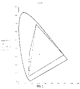
[00153] FIG. 1 illustrates one embodiment of a four primary system including a
red
primary, a green primary, a cyan primary, and a blue primary. The example
shown in FIG. 1
uses the values shown in Table 1.
[00154] In another embodiment, the four primaries include a red primary, a
first green
primary, a second green primary, and a blue primary. In one embodiment, the
red primary has
a dominant wavelength of 615nm, the first green primary has a dominant
wavelength of
525nm, the second green primary has a dominant wavelength of 550nm, and the
blue primary
has a dominant wavelength of 465nm as shown in Table 2. In one embodiment, the
dominant
24
CA 03181332 2022-10-25
WO 2021/222022
PCT/US2021/028857
wavelength is approximately (e.g., within 10%) the value listed in the table
below.
Alternatively, the dominant wavelength is within 5% of the value listed in
the table below.
In yet another embodiment, the dominant wavelength is within 2% of the value
listed in the
table below.
[00155] TABLE 2
u' v'
R 0.680 0.320 0.496 0.526 615nm
G1 0.300 0.700 0.111 0.583 525nm
G2 0.150 0.720 0.053 0.571 550nm
B 0.150 0.060 0.175 0.158 465nm
[00156] FIG. 2 illustrates one embodiment of a four primary system including a
red
primary, a first green primary, a second green primary, and a blue primary.
The example
shown in FIG. 2 uses the values shown in Table 2.
[00157] In another embodiment, the red primary has a dominant wavelength of
615nm, the
first green primary has a dominant wavelength of 520nm, the second green
primary has a
dominant wavelength of 550nm, and the blue primary has a dominant wavelength
of 465nm
as shown in Table 3. In one embodiment, the dominant wavelength is
approximately (e.g.,
within 10%) the value listed in the table below. Alternatively, the dominant
wavelength is
within 5% of the value listed in the table below. In yet another embodiment,
the dominant
wavelength is within 2% of the value listed in the table below.
[00158] TABLE 3
u' v'
R 0.680 0.320 0.496 0.526 615nm
G1 0.302 0.692 0.113 0.582 520nm
G2 0.074 0.834 0.023 0.584 550nm
B 0.150 0.060 0.175 0.158 465nm
CA 03181332 2022-10-25
WO 2021/222022
PCT/US2021/028857
[00159] FIG. 3 illustrates another embodiment of a four primary system
including a red
primary, a first green primary, a second green primary, and a blue primary.
The example
shown in FIG. 3 uses the values shown in Table 3.
[00160] 5 PRIMARY SYSTEMS
[00161] In one embodiment, the multi-primary system includes five primaries.
In one
embodiment, the five primaries include a red primary, a green primary, a cyan
primary, a
blue primary, and a white emitter. In one embodiment, the white emitter is a
D65 emitter. In
one embodiment, the red primary has a dominant wavelength of 615nm, the green
primary
has a dominant wavelength of 545nm, the cyan primary has a dominant wavelength
of
493nm, and the blue primary has a dominant wavelength of 465nm as shown in
Table 4.
[00162] TABLE 4
u' v'
W (D65) 0.313 0.329 0.198 0.468
0.680 0.320 0.496 0.526 615nm
0.265 0.690 0.099 0.578 545nm
0.163 0.342 0.096 0.454 493nm
0.150 0.060 0.175 0.158 465nm
[00163] FIG. 4 illustrates one embodiment of a five primary system including a
red
primary, a green primary, a cyan primary, a blue primary, and a white emitter.
The example
shown in FIG. 4 uses the values shown in Table 4.
[00164] In another embodiment, the five primaries include a red primary, a
yellow
primary, a green primary, a cyan primary, and a blue primary. In one
embodiment, the red
primary has a dominant wavelength of 615nm, the yellow primary has a dominant
wavelength of 570nm, the green primary has a dominant wavelength of 545nm, the
cyan
primary has a dominant wavelength of 493nm, and the blue primary has a
dominant
wavelength of 465nm as shown in Table 5. In one embodiment, the dominant
wavelength is
26
CA 03181332 2022-10-25
WO 2021/222022
PCT/US2021/028857
approximately (e.g., within 10%) the value listed in the table below.
Alternatively, the
dominant wavelength is within 5% of the value listed in the table below. In
yet another
embodiment, the dominant wavelength is within 2% of the value listed in the
table below.
[00165] TABLE 5
u' v'
R 0.680 0.320 0.496 0.526 615nm
Y 0.450 0.547 0.208 0.568 570nm
G 0.265 0.690 0.099 0.578 545nm
C 0.163 0.342 0.096 0.454 493nm
B 0.150 0.060 0.175 0.158 465nm
[00166] FIG. 5 illustrates another embodiment of a five primary system
including a red
primary, a yellow primary, a green primary, a cyan primary, and a blue
primary. The example
shown in FIG. 5 uses the values shown in Table 5.
[00167] In yet another embodiment, the five primaries include a red primary, a
first green
primary, a second green primary, a blue primary, and a white emitter. In one
embodiment, the
white emitter is a D65 emitter. In one embodiment, the red primary has a
dominant
wavelength of 615nm, the first green primary has a dominant wavelength of
525nm, the
second green primary has a dominant wavelength of 550nm, and the blue primary
has a
dominant wavelength of 465nm as shown in Table 6. In one embodiment, the
dominant
wavelength is approximately (e.g., within 10%) the value listed in the table
below.
Alternatively, the dominant wavelength is within 5% of the value listed in
the table below.
In yet another embodiment, the dominant wavelength is within 2% of the value
listed in the
table below.
[00168] TABLE 6
u' v'
W (D65) 0.313 0.329 0.198 0.468
27
CA 03181332 2022-10-25
WO 2021/222022
PCT/US2021/028857
0.680 0.320 0.496 0.526 615nm
G1 0.300 0.700 0.111 0.583 525nm
G2 0.150 0.720 0.053 0.571 550nm
0.150 0.060 0.175 0.158 465nm
[00169] FIG. 6 illustrates another embodiment of a five primary system
including a red
primary, a first green primary, a second green primary, a blue primary, and a
white emitter.
The example shown in FIG. 6 uses the values shown in Table 6.
[00170] In another embodiment, the red primary has a dominant wavelength of
615nm, the
first green primary has a dominant wavelength of 520nm, the second green
primary has a
dominant wavelength of 550nm, and the blue primary has a dominant wavelength
of 465nm
as shown in Table 7. In one embodiment, the dominant wavelength is
approximately (e.g.,
within 10%) the value listed in the table below. Alternatively, the dominant
wavelength is
within 5% of the value listed in the table below. In yet another embodiment,
the dominant
wavelength is within 2% of the value listed in the table below.
[00171] TABLE 7
u' v'
W (D65) 0.313 0.329 0.198 0.468
0.680 0.320 0.496 0.526 615nm
G1 0.302 0.692 0.113 0.582 520nm
G2 0.150 0.720 0.053 0.571 550nm
0.150 0.060 0.175 0.158 465nm
[00172] FIG. 7 illustrates another embodiment of a five primary system
including a red
primary, a first green primary, a second green primary, a blue primary, and a
white emitter.
The example shown in FIG. 7 uses the values shown in Table 7.
[00173] 6 PRIMARY SYSTEMS
28
CA 03181332 2022-10-25
WO 2021/222022
PCT/US2021/028857
[00174] In one embodiment, the multi-primary system includes six primaries. In
one
preferred embodiment, the six primaries include a red primary, a green
primary, a blue
primary, a cyan primary, a magenta primary, and a yellow primary.
[00175] 6P-B
[00176] 6P-B is a color set that uses the same RGB values that are defined in
the ITU-R
BT.709-6 television standard. The gamut includes these RGB primary colors and
then adds
three more color primaries orthogonal to these based on the white point. The
white point used
in 6P-B is D65 (ISO 11664-2).
[00177] In one embodiment, the red primary has a dominant wavelength of 609nm,
the
yellow primary has a dominant wavelength of 571m, the green primary has a
dominant
wavelength of 552nm, the cyan primary has a dominant wavelength of 491m, and
the blue
primary has a dominant wavelength of 465nm as shown in Table 8. In one
embodiment, the
dominant wavelength is approximately (e.g., within 10%) the value listed in
the table below.
Alternatively, the dominant wavelength is within 5% of the value listed in
the table below.
In yet another embodiment, the dominant wavelength is within 2% of the value
listed in the
table below.
[00178] TABLE 8
u' v'
W (D65) 0.3127 0.3290 0.1978 0.4683
0.6400 0.3300 0.4507 0.5228 609nm
0.3000 0.6000 0.1250 0.5625 552nm
0.1500 0.0600 0.1754 0.1578 464nm
0.1655 0.3270 0.1041 0.4463 491m
0.3221 0.1266 0.3325 0.2940
0.4400 0.5395 0.2047 0.5649 571m
[00179] FIG. 8 illustrates 6P-B compared to ITU-R BT.709-6.
[00180] 6P-C
29
CA 03181332 2022-10-25
WO 2021/222022
PCT/US2021/028857
[00181] 6P-C is based on the same RGB primaries defined in SMPTE RP431-2
projection
recommendation. Each gamut includes these RGB primary colors and then adds
three more
color primaries orthogonal to these based on the white point. The white point
used in 6P-B is
D65 (ISO 11664-2). Two versions of 6P-C are used. One is optimized for a D60
white point
(SMPTE 5T2065-1), and the other is optimized for a D65 white point.
[00182] In one embodiment, the red primary has a dominant wavelength of 615nm,
the
yellow primary has a dominant wavelength of 570nm, the green primary has a
dominant
wavelength of 545nm, the cyan primary has a dominant wavelength of 493nm, and
the blue
primary has a dominant wavelength of 465nm as shown in Table 9. In one
embodiment, the
dominant wavelength is approximately (e.g., within 10%) the value listed in
the table below.
Alternatively, the dominant wavelength is within 5% of the value listed in
the table below.
In yet another embodiment, the dominant wavelength is within 2% of the value
listed in the
table below.
[00183] TABLE 9
u' v'
W (D60) 0.3217 0.3377 0.2008 0.4742
0.6800 0.3200 0.4964 0.5256 615nm
0.2650 0.6900 0.0980 0.5777 545nm
0.1500 0.0600 0.1754 0.1579 465nm
0.1627 0.3419 0.0960 0.4540 493nm
0.3523 0.1423 0.3520 0.3200
0.4502 0.5472 0.2078 0.5683 570nm
[00184] FIG. 9 illustrates 6P-C compared to SMPTE RP431-2 for a D60 white
point.
[00185] In one embodiment, the red primary has a dominant wavelength of 615nm,
the
yellow primary has a dominant wavelength of 570nm, the green primary has a
dominant
wavelength of 545nm, the cyan primary has a dominant wavelength of 423nm, and
the blue
CA 03181332 2022-10-25
WO 2021/222022
PCT/US2021/028857
primary has a dominant wavelength of 465nm as shown in Table 10. In one
embodiment, the
dominant wavelength is approximately (e.g., within 10%) the value listed in
the table below.
Alternatively, the dominant wavelength is within 5% of the value listed in
the table below.
In yet another embodiment, the dominant wavelength is within 2% of the value
listed in the
table below.
[00186] TABLE 10
u' v'
W (D65) 0.3127 0.3290 0.1978 0.4683
0.6800 0.3200 0.4964 0.5256 615nm
0.2650 0.6900 0.0980 0.5777 545nm
0.1500 0.0600 0.1754 0.1579 465nm
0.1617 0.3327 0.0970 0.4490 492nm
0.3383 0.1372 0.3410 0.3110
0.4470 0.5513 0.2050 0.5689 570nm
[00187] FIG. 10 illustrates 6P-C compared to SMPTE RP431-2 for a D65 white
point.
[00188] SUPER 6P
[00189] One of the advantages of ITU-R BT.2020 is that it can include all of
the Pointer
colors and that increasing primary saturation in a six-color primary design
could also do this.
Pointer is described in "The Gamut of Real Surface Colors, M.R. Pointer,
Published in
Colour Research and Application Volume #5, Issue #3 (1980), which is
incorporated herein
by reference in its entirety. However, extending the 6P gamut beyond SMPTE
RP431-2 ("6P-
C") adds two problems. The first problem is the requirement to narrow the
spectrum of the
extended primaries. The second problem is the complexity of designing a
backwards
compatible system using color primaries that are not related to current
standards. But in some
cases, there may be a need to extend the gamut beyond 6P-C and avoid these
problems. If the
goal is to encompass Pointer's data set, then it is possible to keep most of
the 6P-C system
and only change the cyan color primary position. In one embodiment, the cyan
color primary
31
CA 03181332 2022-10-25
WO 2021/222022
PCT/US2021/028857
position is located so that the gamut edge encompasses all of Pointer's data
set. In another
embodiment, the cyan color primary position is a location that limits maximum
saturation.
With 6P-C, cyan is positioned as u'=0.096, v'=0.454. In one embodiment of
Super 6P, cyan
is moved to u'=0.075, v'=0.430 ("Super 6Pa" (S6Pa)). Advantageously, this
creates anew
gamut that covers Pointer's data set almost in its entirety. FIG. 11
illustrates Super 6Pa
compared to 6P-C.
[00190] Table 11 is a table of values for Super 6Pa. The definition of x,y are
described in
ISO 11664-3:2012/CIE S 014 Part 3, which is incorporated herein by reference
in its entirety.
The definition of u ',v ' are described in ISO 11664-5:2016/CIE S 014 Part 5,
which is
incorporated herein by reference in its entirety. defines each color primary
as dominant
color wavelength for RGB and complementary wavelengths CMY.
[00191] TABLE 11
v
W (D60) 0.3217 0.3377 0.2008 0.4742
W (D65) 0.3127 0.3290 0.1978 0.4683
R 0.6800 0.3200 0.4964 0.5256 615nm
G 0.2650 0.6900 0.0980 0.5777 545nm
B 0.1500 0.0600 0.1754 0.1579 465nm
C 0.1211 0.3088 0.0750 0.4300 490nm
M 0.3523 0.1423 0.3520 0.3200
Y 0.4502 0.5472 0.2078 0.5683 570nm
[00192] In an alternative embodiment, the saturation is expanded on the same
hue angle as
6P-C as shown in FIG. 12. Advantageously, this makes backward compatibility
less
complicated. However, this requires much more saturation (i.e., narrower
spectra). In another
embodiment of Super 6P, cyan is moved to u'=0.067, v'=0.449 ("Super 6Pb"
(S6Pb)).
Additionally, FIG. 12 illustrates Super 6Pb compared to Super 6Pa and 6P-C.
32
CA 03181332 2022-10-25
WO 2021/222022
PCT/US2021/028857
[00193] Table 12 is a table of values for Super 6Pb. The definition of x,y are
described in
ISO 11664-3:2012/CIE S 014 Part 3, which is incorporated herein by reference
in its entirety.
The definition of u ',v' are described in ISO 11664-5:2016/CIE S 014 Part 5,
which is
incorporated herein by reference in its entirety. defines each color primary
as dominant
color wavelength for RGB and complementary wavelengths CMY.
[00194] TABLE 12
u' v'
W (ACES D60) 0.32168 0.33767 0.2008 0.4742
W (D65) 0.3127 0.3290 0.1978 0.4683
0.6800 0.3200 0.4964 0.5256 615nm
0.2650 0.6900 0.0980 0.5777 545nm
0.1500 0.0600 0.1754 0.1579 465nm
0.1156 0.3442 0.0670 0.4490 493nm
0.3523 0.1423 0.3520 0.3200
0.4502 0.5472 0.2078 0.5683 570nm
[00195] In another embodiment, the six primaries include a red primary, a
yellow primary,
a green primary, a cyan primary, a blue primary, and white emitter. In one
embodiment, the
white emitter is a D65 white emitter. In one embodiment, the red primary has a
dominant
wavelength of 615nm, the yellow primary has a dominant wavelength of 570nm,
the green
primary has a dominant wavelength of 545nm, the cyan primary has a dominant
wavelength
of 493nm, and the blue primary has a dominant wavelength of 465nm as shown in
Table 13.
In one embodiment, the dominant wavelength is approximately (e.g., within
10%) the value
listed in the table below. Alternatively, the dominant wavelength is within
5% of the value
listed in the table below. In yet another embodiment, the dominant wavelength
is within 2%
of the value listed in the table below.
[00196] TABLE 13
u' v'
33
CA 03181332 2022-10-25
WO 2021/222022
PCT/US2021/028857
W (D65) 0.313 0.329 0.198 0.468
0.680 0.320 0.496 0.526 615nm
0.450 0.547 0.208 0.568 570nm
0.265 0.690 0.099 0.578 545nm
0.163 0.342 0.096 0.454 493nm
0.150 0.060 0.175 0.158 465nm
[00197] FIG. 13 illustrates one embodiment of a six primary system including a
red
primary, a yellow primary, a green primary, a cyan primary, a blue primary,
and a white
emitter. The example shown in FIG. 13 uses the values shown in Table 13.
[00198] In yet another embodiment, the six primaries include a red primary, a
first green
primary, a second green primary, a blue primary, a first white emitter, and a
second white
emitter. In one embodiment, the first white emitter is a D65 white emitter. In
one
embodiment, the second white emitter is a D25 white emitter. In one
embodiment, the red
primary has a dominant wavelength of 615nm, the first green primary has a
dominant
wavelength of 520nm, the second green primary has a dominant wavelength of
550nm, and
the blue primary has a dominant wavelength of 465nm as shown in Table 14. In
an
alternative embodiment, the first green primary has a dominant wavelength of
525nm. In one
embodiment, the dominant wavelength is approximately (e.g., within 10%) the
value listed
in the table below. Alternatively, the dominant wavelength is within 5% of
the value listed
in the table below. In yet another embodiment, the dominant wavelength is
within 2% of the
value listed in the table below.
[00199] TABLE 14
u' v'
W (D65) 0.313 0.329 0.198 0.468
W (D25) 0.477 0.414 0.272 0.531
0.680 0.320 0.496 0.526 615nm
G1 0.300 0.700 0.111 0.583 525nm
34
CA 03181332 2022-10-25
WO 2021/222022
PCT/US2021/028857
G2 0.150 0.720 0.053 0.571 550nm
0.150 0.060 0.175 0.158 465nm
[00200] FIG. 14 illustrates one embodiment of a six primary system including a
red
primary, a first green primary, a second green primary, a blue primary, a
first white emitter,
and a second white emitter. The example shown in FIG. 14 uses the values shown
in Table
14.
[00201] In still another embodiment, the six primaries include a red primary,
a green
primary, a blue primary, a first white emitter, a second white emitter, and a
third white
emitter. In one embodiment, the first white emitter is a D80 white emitter. In
one
embodiment, the second white emitter is a D20 white emitter. In one
embodiment, the third
white emitter is a D45 white emitter. In a preferred embodiment, the third
white emitter
includes a green bias (e.g., 40% green, 60% D45). In one embodiment, the red
primary has a
dominant wavelength of 630nm, the green primary has a dominant wavelength of
532nm, and
the blue primary has a dominant wavelength of 467nm as shown in Table 15. In
one
embodiment, the dominant wavelength is approximately (e.g., within 10%) the
value listed
in the table below. Alternatively, the dominant wavelength is within 5% of
the value listed
in the table below. In yet another embodiment, the dominant wavelength is
within 2% of the
value listed in the table below.
[00202] TABLE 15
W-R (D25) 0.5265 0.4133
W-G (D45-G) 0.2855 0.5393
W-B (D65) 0.2940 0.3094
0.708 0.292 630nm
0.170 0.797 532nm
0.131 0.046 467nm
CA 03181332 2022-10-25
WO 2021/222022
PCT/US2021/028857
[00203] FIG. 15A illustrates one embodiment of a six primary system including
a red
primary, a green primary, a blue primary, a first white emitter, a second
white emitter, and a
third white emitter. The example shown in FIG. 15A uses the values shown in
Table 15.
Advantageously, this embodiment allows for fewer metameric errors.
[00204] FIG. 15B illustrates an example of the emission spectra of a six
primary system
including a red primary, a green primary, a blue primary, a first white
emitter, a second white
emitter, and a third white emitter. The example shown in FIG. 15B uses the
values shown in
Table 15.
[00205] Alternatively, the six primary system includes a first red primary, a
second red
primary, a first green primary, a second green primary, a first blue primary,
and a second blue
primary. The first red primary, the first green primary, and the first blue
primary are
preferably narrow band primaries. The second red primary, the second green
primary, and the
second blue primary are preferably wide band primaries. In one embodiment, the
first red
primary has a dominant wavelength of 630nm, the first green primary has a
dominant
wavelength of 532nm, and the first blue primary has a dominant wavelength of
4671m. In
one embodiment, the dominant wavelength is approximately (e.g., within 10%)
the value
recited above. Alternatively, the dominant wavelength is within 5% of the
value recited
above. In yet another embodiment, the dominant wavelength is within 2% of the
value
recited above.
[00206] FIG. 15C illustrates an example of the emission spectra of a six
primary system
including a first red primary, a second red primary, a first green primary, a
second green
primary, a first blue primary, and a second blue primary. Advantageously, this
embodiment
also allows for fewer metameric errors.
[00207] In a preferred embodiment, a matrix is created from XYZ values of each
of the
primaries (e.g., the at least four primaries, the at least five primaries, the
at least six
36
CA 03181332 2022-10-25
WO 2021/222022
PCT/US2021/028857
primaries). As the XYZ values of the primaries change, the matrix changes.
Additional
details about the matrix are described below.
[00208] FORMATTING AND TRANSPORTATION OF MULTI-PRIMARY SIGNALS
[00209] The present invention includes three different methods to format video
for
transport: System 1, System 2, and System 3. System 1 is comprised of an
encode and decode
system, which can be divided into base encoder and digitation, image data
stacking, mapping
into the standard data transport, readout, unstack, and finally image
decoding. In one
embodiment, the basic method of this system is to combine opposing color
primaries within
the three standard transport channels and identify them by their code value.
[00210] System 2 uses a sequential method where three color primaries are
passed to the
transport format as full bit level image data and inserted as normal. The
three additional
channels are delayed by one pixel and then placed into the transport instead
of the first colors.
This is useful in situations where quantizing artifacts may be critical to
image performance.
In one embodiment, this system is comprised of the six primaries (e.g., RGB
plus a method to
delay the CYM colors for injection), image resolution identification to allow
for pixel count
synchronization, start of video identification, and RGB Delay.
[00211] System 3 utilizes a dual link method where two wires are used. In one
embodiment, a first set of three channels (e.g., RGB) are sent to link A and a
second set of
three channels (e.g., CYM) is sent to link B. Once they arrive at the image
destination, they
are recombined.
[00212] To
transport up to six color components (e.g., four, five, or six), System 1,
System
2, or System 3 can be used as described. If four color components are used,
two of the
channels are set to "0". If five color components are used, one of the
channels is set to "0".
Advantageously, this transportation method works for all primary systems
described herein
that include up to six color components.
37
CA 03181332 2022-10-25
WO 2021/222022
PCT/US2021/028857
[00213] COMPARISON OF THREE SYSTEMS
[00214] Advantageously, System 1 fits within legacy SDI, CTA, and Ethernet
transports.
Additionally, System 1 has zero latency processing for conversion to an RGB
display.
However, System 1 is limited to 11-bit words.
[00215] System 2 is advantageously operable to transport 6 channels using 16-
bit words
with no compression. Additionally, System 2 fits within newer SDI, CTA, and
Ethernet
transport formats. However, System 2 requires double bit rate speed. For
example, a 4K
image requires a data rate for an 8K RGB image.
[00216] In comparison, System 3 is operable to transport up to 6 channels
using 16-bit
words with compression and at the same data required for a specific
resolution. For example,
a data rate for an RGB image is the same as for a 6P image using System 3.
However, System
3 requires a twin cable connection within the video system.
[00217] NOMENCLATURE
[00218] In one embodiment, a standard video nomenclature is used to better
describe each
system.
[00219] R describes red data as linear light. G describes green data as linear
light. B
describes blue data as linear light. C describes cyan data as linear light. M
describes magenta
data as linear light. r and/or Y describe yellow data as linear light.
[00220] R' describes red data as non-linear light. G' describes green data as
non-linear
light. B' describes blue data as non-linear light. C' describes cyan data as
non-linear light. M'
describes magenta data as non-linear light. Yc and/or Y' describe yellow data
as non-linear
light.
[00221] Y6 describes the luminance sum of RGBCMY data. YRGB describes a System
2
encode that is the linear luminance sum of the RGB data. Yovry describes a
System 2 encode
that is the linear luminance sum of the CMY data.
38
CA 03181332 2022-10-25
WO 2021/222022
PCT/US2021/028857
[00222] CR describes the data value of red after subtracting linear image
luminance. CB
describes the data value of blue after subtracting linear image luminance. Cc
describes the
data value of cyan after subtracting linear image luminance. Cy describes the
data value of
yellow after subtracting linear image luminance.
[00223] TRGB describes a System 2 encode that is the nonlinear luminance sum
of the
RGB data. Y 'Civiy describes a System 2 encode that is the nonlinear luminance
sum of the
CMY data. -Y describes the sum of RGB data subtracted from Y6.
[00224] C 'R describes the data value of red after subtracting nonlinear image
luminance.
C '13 describes the data value of blue after subtracting nonlinear image
luminance. C'c
describes the data value of cyan after subtracting nonlinear image luminance.
C 'y describes
the data value of yellow after subtracting nonlinear image luminance.
[00225] B+Y describes a System 1 encode that includes either blue or yellow
data. G+M
describes a System 1 encode that includes either green or magenta data. R+C
describes a
System 1 encode that includes either green or magenta data.
[00226] CR+Cc describes a System 1 encode that includes either color
difference data.
CB+Cy describes a System 1 encode that includes either color difference data.
[00227] 4:4:4 describes full bandwidth sampling of a color in an RGB system.
4:4:4:4:4:4
describes full sampling of a color in an RGBCMY system. 4:2:2 describes an
encode where a
full bandwidth luminance channel (Y) is used to carry image detail and the
remaining
components are half sampled as a Cb Cr encode. 4:2:2:2:2 describes an encode
where a full
bandwidth luminance channel (Y) is used to carry image detail and the
remaining components
are half sampled as a Cb Cr Cy Cc encode. 4:2:0 describes a component system
similar to
4:2:2, but where Cr and Cb samples alternate per line. 4:2:0:2:0 describes a
component
system similar to 4:2:2, but where Cr, Cb, Cy, and Cc samples alternate per
line.
39
CA 03181332 2022-10-25
WO 2021/222022
PCT/US2021/028857
[00228] Constant luminance is the signal process where luminance (Y) are
calculated in
linear light. Non-constant luminance is the signal process where luminance (Y)
are calculated
in nonlinear light.
[00229] DERIVING COLOR COMPONENTS
[00230] When using a color difference method (4:2:2), several components need
specific
processing so that they can be used in lower frequency transports. These are
derived as:
[00231] Ye: = 0.1063R' + 0.2319511' + 0.3576G' + 0.19685C + 0.0361B' +
0.0712M'
[00232] G'e, ¨ __ 1 0.3576Y) (0.1063k) ¨ (0.03610 ¨ (0.196850 ¨ (0.2319511c)
¨
(0.07120)
[00233] ¨Y' = Ye: ¨ (C' + )Jc' + M')
Yc"¨Y'
1002341 CR = CR = Cc = Cy =
1.7874 1.9278 1.6063 1.5361
[00235] = ¨cR" B, = cB" = cc' -y6' yc, = CY6¨
1.7874 1.9278 1.6063 1.5361
[00236] The ratios for Cr, Cb, Cc, and Cy are also valid in linear light
calcuations.
[00237] Magenta can be calculated as follows:
[00238] M = B +R or M = ¨B+R
B xR BxR
[00239] SYSTEM 1
[00240] In one embodiment, the multi-primary color system is compatible with
legacy
systems. A backwards compatible multi-primary color system is defined by a
sampling
method. In one embodiment, the sampling method is 4:4:4. In one embodiment,
the sampling
method is 4:2:2. In another embodiment, the sampling method is 4:2:0. In one
embodiment of
a backwards compatible multi-primary color system, new encode and decode
systems are
divided into the steps of performing base encoding and digitization, image
data stacking,
mapping into the standard data transport, readout, unstacking, and image
decoding ("System
1"). In one embodiment, System 1 combines opposing color primaries within
three standard
CA 03181332 2022-10-25
WO 2021/222022
PCT/US2021/028857
transport channels and identifies them by their code value. In one embodiment
of a
backwards compatible multi-primary color system, the processes are analog
processes. In
another embodiment of a backwards compatible multi-primary color system, the
processes
are digital processes.
[00241] In one embodiment, the sampling method for a multi-primary color
system is a
4:4:4 sampling method. Black and white bits are redefined. In one embodiment,
putting black
at midlevel within each data word allows the addition of CYM color data.
[00242] FIG. 16 illustrates an embodiment of an encode and decode system for a
multi-
primary color system. In one embodiment, the multi-primary color encode and
decode system
is divided into a base encoder and digitation, image data stacking, mapping
into the standard
data transport, readout, unstack, and finally image decoding ("System 1"). In
one
embodiment, the method of this system combines opposing color primaries within
the three
standard transport channels and identifies them by their code value. In one
embodiment, the
encode and decode for a multi-primary color system are analog-based. In
another
embodiment, the encode and decode for a multi-primary color system are digital-
based.
System 1 is designed to be compatible with lower bandwidth systems and allows
a maximum
of 11 bits per channel and is limited to sending only three channels of up to
six primaries at a
time. In one embodiment, it does this by using a stacking system where either
the color
channel or the complementary channel is decoded depending on the bit level of
that one
channel.
[00243] SYSTEM 2
[00244] FIG. 17 illustrates a sequential method where three color primaries
are passed to
the transport format as full bit level image data and inserted as normal
("System 2"). The
three additional channels are delayed by one pixel and then placed into the
transport instead
of the first colors. This method is useful in situations where quantizing
artifacts is critical to
41
CA 03181332 2022-10-25
WO 2021/222022
PCT/US2021/028857
image performance. In one embodiment, this system is comprised of six
primaries
(RGBCYM), a method to delay the CYM colors for injection, image resolution
identification
to all for pixel count synchronization, start of video identification, RGB
delay, and for
YCCCCC systems, logic to select the dominant color primary. The advantage of
System 2 is
that full bit level video can be transported, but at double the normal data
rate.
[00245] SYSTEM 3
[00246] FIG. 18 illustrates one embodiment of a system encode and decode
process using
a dual link method ("System 3"). System 3 utilizes a dual link method where
two wires are
used. In one embodiment, RGB is sent to link A and CYM is sent to link B.
After arriving at
the image destination, the two links are recombined.
[00247] System 3 is simpler and more straight forward than Systems 1 and 2.
The
advantage with this system is that adoption is simply to format non-RGB
primaries (e.g.,
CYM) on a second link. So, in one example, for an SDI design, RGB is sent on a
standard
SDI stream just as it is currently done. There is no modification to the
transport and this link
is operable to be sent to any RGB display requiring only the compensation for
the luminance
difference because the CYM components are not included. CYM data is
transported in the
same manner as RGB data. This data is then combined in the display to make up
a 6P image.
The downside is that the system requires two wires to move one image. This
system is
operable to work with most any format including SMPTE 5T292, 424, 2082, and
2110. It
also is operable to work with dual HDMI/CTA connections. In one embodiment,
the system
includes at least one transfer function (e.g., OETF, EOTF).
[00248] FIG. 19 illustrates one embodiment of an encoding process using a dual
link
method.
[00249] FIG. 20 illustrates one embodiment of a decoding process using a dual
link
method.
42
CA 03181332 2022-10-25
WO 2021/222022
PCT/US2021/028857
[00250] TRANSFER FUNCTIONS
[00251] The system design minimizes limitations to use standard transfer
functions for
both encode and/or decode processes. Current practices used in standards
include, but are not
limited to, ITU-R BT.1886, ITU-R BT.2020, SMPTE ST274, SMPTE ST296, SMPTE
ST2084, and ITU-R BT.2100. These standards are compatible with this system and
require
no modification.
[00252] Encoding and decoding 6P images is formatted into several different
configurations to adapt to image transport frequency limitations. The highest
quality transport
is obtained by keeping all components as RGBCMY components. This uses the
highest
sampling frequencies and requires the most signal bandwidth. An alternate
method is to sum
the image details in a luminance channel at full bandwidth and then send the
color difference
signals at half or quarter sampling (e.g., Y Cr Cb Cc Cy). This allows a
similar image to pass
through lower bandwidth transports.
[00253] SIX-PRIMARY COLOR ENCODE USING A 4:4:4 SAMPLING METHOD
[00254] FIG. 21 illustrates one embodiment of a six-primary color system
encode using a
4:4:4 sampling method.
[00255] Subjective testing during the development and implementation of the
current
digital cinema system (DCI Version 1.2) showed that perceptible quantizing
artifacts were
not noticeable with system bit resolutions higher than 11 bits. Current serial
digital transport
systems support 12 bits. Remapping six color components to a 12-bit stream is
accomplished
by lowering the bit limit to 11 bits (values 0 to 2047) for 12-bit serial
systems or 9 bits
(values 0 to 512) for 10-bit serial systems. This process is accomplished by
processing
RGBCYM video information through a standard Optical Electronic Transfer
Function
(OETF) (e.g., ITU-R BT.709-6), digitizing the video information as four
samples per pixel,
and quantizing the video information as 11-bit or 9-bit.
43
CA 03181332 2022-10-25
WO 2021/222022
PCT/US2021/028857
[00256] In another embodiment, the RGBCYM video information is processed
through a
standard Optical Optical Transfer Function (00TF). In yet another embodiment,
the
RGBCYM video information is processed through a Transfer Function (TF) other
than OETF
or 00TF. TFs consist of two components, a Modulation Transfer Function (MTF)
and a
Phase Transfer Function (PTF). The MTF is a measure of the ability of an
optical system to
transfer various levels of detail from object to image. In one embodiment,
performance is
measured in terms of contrast (degrees of gray), or of modulation, produced
for a perfect
source of that detail level. The PTF is a measure of the relative phase in the
image(s) as a
function of frequency. A relative phase change of 180 , for example, indicates
that black and
white in the image are reversed. This phenomenon occurs when the TF becomes
negative.
[00257] There are several methods for measuring MTF. In one embodiment, MTF is
measured using discrete frequency generation. In one embodiment, MTF is
measured using
continuous frequency generation. In another embodiment, MTF is measured using
image
scanning. In another embodiment, MTF is measured using waveform analysis.
[00258] In one embodiment, the six-primary color system is for a 12-bit serial
system.
Current practices normally set black at bit 0 and white at bit 4095 for 12-bit
video. In order to
package six colors into the existing three-serial streams, the bit defining
black is moved to bit
2048. Thus, the new encode has RGB values starting at 2048 for black and bit
4095 for white
and CYM values starting at bit 2047 for black and bit 0 as white. In another
embodiment, the
six-primary color system is for a 10-bit serial system.
[00259] FIG. 22 illustrates one embodiment for a method to package six
channels of
primary information into the three standard primary channels used in current
serial video
standards by modifying bit numbers for a 12-bit SDI and a 10-bit SDI. FIG. 23
illustrates a
simplified diagram estimating perceived viewer sensation as code values define
each hue
angle. Table 16 and Table 17 list bit assignments for computer, production,
and broadcast for
44
CA 03181332 2022-10-25
WO 2021/222022
PCT/US2021/028857
a 12-bit system and a 10-bit system, respectively. In one embodiment,
"Computer" refers to
bit assignments compatible with CTA 861-G, November 2016, which is
incorporated herein
by reference in its entirety. In one embodiment, "Production" and/or
"Broadcast" refer to bit
assignments compatible with SMPTE ST 2082-0 (2016), SMPTE ST 2082-1 (2015),
SMPTE
ST 2082-10 (2015), SMPTE ST 2082-11(2016), SMPTE ST 2082-12 (2016), SMPTE ST
2110-10 (2017), SMPTE ST 2110-20 (2017), SMPTE ST 2110-21 (2017), SMPTE ST
2110-
30 (2017), SMPTE ST 2110-31 (2018), and/or SMPTE ST 2110-40 (2018), each of
which is
incorporated herein by reference in its entirety.
[00260] TABLE 16: 12-Bit Assignments
Computer Production Broadcast
RGB CYM RGB CYM RGB CYM
Peak Brightness 4095 0 4076 16 3839 256
Minimum Brightness 2048 2047 2052 2032 2304 1792
[00261] TABLE 17: 10-Bit Assignments
Computer Production Broadcast
RGB CYM RGB CYM RGB CYM
Peak Brightness 1023 0 1019 4 940 64
Minimum Brightness 512 511 516 508 576 448
[00262] In one embodiment, the OETF process is defined in ITU-R BT.709-6,
which is
incorporated herein by reference in its entirety. In one embodiment, the OETF
process is
defined in ITU-R BT.709-5, which is incorporated herein by reference in its
entirety. In
another embodiment, the OETF process is defined in ITU-R BT.709-4, which is
incorporated
herein by reference in its entirety. In yet another embodiment, the OETF
process is defined in
ITU-R BT.709-3, which is incorporated herein by reference in its entirety. In
yet another
CA 03181332 2022-10-25
WO 2021/222022
PCT/US2021/028857
embodiment, the OETF process is defined in ITU-R BT.709-2, which is
incorporated herein
by reference in its entirety. In yet another embodiment, the OETF process is
defined in ITU-
R BT.709-1, which is incorporated herein by reference in its entirety.
[00263] In one embodiment, the encoder is a non-constant luminance encoder. In
another
embodiment, the encoder is a constant luminance encoder.
[00264] SIX-PRIMARY COLOR PACKING/STACKING USING A 4:4:4 SAMPLING
METHOD
[00265] FIG. 24 illustrates one embodiment for a method of stacking/encoding
six-primary
color information using a 4:4:4 video system. Image data must be assembled
according the
serial system used. This is not a conversion process, but instead is a
packing/stacking process.
In one embodiment, the packing/stacking process is for a six-primary color
system using a
4:4:4 sampling method.
[00266] FIG. 25 illustrates one embodiment for a method of unstacking/decoding
six-
primary color information using a 4:4:4 video system. In one embodiment, the
RGB channels
and the CYM channels are combined into one 12-bit word and sent to a
standardized
transport format. In one embodiment, the standardized transport format is
SMPTE 5T424
SDI. In one embodiment, the decode is for a non-constant luminance, six-
primary color
system. In another embodiment, the decode is for a constant luminance, six-
primary color
system. In yet another embodiment, an electronic optical transfer function
(EOTF) (e.g., ITU-
R BT.1886) coverts image data back to linear for display. In one embodiment,
the EOTF is
defined in ITU-R BT.1886 (2011), which is incorporated herein by reference in
its entirety.
FIG. 26 illustrates one embodiment of a 4:4:4 decoder.
[00267] System 2 uses sequential mapping to the standard transport format, so
it includes a
delay for the CYM data. The CYM data is recovered in the decoder by delaying
the RGB
data. Since there is no stacking process, the full bit level video can be
transported. For
46
CA 03181332 2022-10-25
WO 2021/222022
PCT/US2021/028857
displays that are using optical filtering, this RGB delay could be removed and
the process of
mapping image data to the correct filter could be eliminated by assuming this
delay with
placement of the optical filter and the use of sequential filter colors.
[00268] Two methods can be used based on the type of optical filter used.
Since this
system is operating on a horizontal pixel sequence, some vertical compensation
is required
and pixels are rectangular. This can be either as a line double repeat using
the same
RGBCYM data to fill the following line as shown in FIG. 27, or could be
separated as RGB
on line one and CYM on line two as shown in FIG. 28. The format shown in FIG.
28 allows
for square pixels, but the CMY components requires a line delay for
synchronization. Other
patterns eliminating the white subpixel are also compatible with the present
invention.
[00269] FIG. 29 illustrates an embodiment of the present invention for sending
six primary
colors to a standardized transport format using a 4:4:4 encoder according to
System 2.
Encoding is straight forward with a path for RGB sent directly to the
transport format. RGB
data is mapped to each even numbered data segment in the transport. CYM data
is mapped to
each odd numbered segment. Because different resolutions are used in all of
the standardized
transport formats, there must be identification for what they are so that the
start of each
horizontal line and horizontal pixel count can be identified to time the
RGB/CYM mapping to
the transport. The identification is the same as currently used in each
standardized transport
function. Table 18, Table 19, Table 20, and Table 21 list 16-bit assignments,
12-bit
assignments, 10-bit assignments, and 8-bit assignments, respectively. In one
embodiment,
"Computer" refers to bit assignments compatible with CTA 861-G, November 2016,
which is
incorporated herein by reference in its entirety. In one embodiment,
"Production" and/or
"Broadcast" refer to bit assignments compatible with SMPTE ST 2082-0 (2016),
SMPTE ST
2082-1 (2015), SMPTE ST 2082-10 (2015), SMPTE ST 2082-11(2016), SMPTE ST 2082-
12 (2016), SMPTE ST 2110-10 (2017), SMPTE ST 2110-20 (2017), SMPTE ST 2110-21
47
CA 03181332 2022-10-25
WO 2021/222022
PCT/US2021/028857
(2017), SMPTE ST 2110-30 (2017), SMPTE ST 2110-31 (2018), and/or SMPTE ST 2110-
40
(2018), each of which is incorporated herein by reference in its entirety.
[00270] TABLE 18: 16-Bit Assignments
Computer Production
RGB CYM RGB CYM
Peak Brightness 65536 65536 65216 65216
Minimum Brightness 0 0 256 256
[00271] TABLE 19: 12-Bit Assignments
Computer Production Broadcast
RGB CYM RGB CYM RGB CYM
Peak Brightness 4095 4095 4076 4076 3839 3839
Minimum Brightness 0 0 16 16 256 256
[00272] TABLE 20: 10-Bit Assignments
Computer Production Broadcast
RGB CYM RGB CYM RGB CYM
Peak Brightness 1023 1023 1019 1019 940 940
Minimum Brightness 0 0 4 4 64 64
[00273] TABLE 21: 8-Bit Assignments
Computer Production Broadcast
RGB CYM RGB CYM RGB CYM
Peak Brightness 255 255 254 254 235 235
Minimum Brightness 0 0 1 1 16 16
48
CA 03181332 2022-10-25
WO 2021/222022
PCT/US2021/028857
[00274] The decode adds a pixel delay to the RGB data to realign the channels
to a
common pixel timing. EOTF is applied and the output is sent to the next device
in the system.
Metadata based on the standardized transport format is used to identify the
format and image
resolution so that the unpacking from the transport can be synchronized. FIG.
30 shows one
embodiment of a decoding with a pixel delay.
[00275] In one embodiment, the decoding is 4:4:4 decoding. With this method,
the six-
primary color decoder is in the signal path, where 11-bit values for RGB are
arranged above
data level 2048, while CYM levels are arranged below data level 2047 as 11-
bit. If the same
data set is sent to a display and/or process that is not operable for six-
primary color
processing, the image data is assumed as black at 0 level as a full 12-bit
word. Decoding
begins by tapping image data prior to the unstacking process.
[00276] SIX-PRIMARY COLOR ENCODE USING A 4:2:2 SAMPLING METHOD
[00277] In one embodiment, the packing/stacking process is for a six-primary
color system
using a 4:2:2 sampling method. In order to fit the new six-primary color
system into a lower
bandwidth serial system, while maintaining backwards compatibility, the
standard method of
converting from RGBCYM to a luminance and a set of color difference signals
requires the
addition of at least one new image designator. In one embodiment, the encoding
and/or
decoding process is compatible with transport through SMPTE ST 292-0 (2011),
SMPTE ST
292-1 (2011, 2012, and/or 2018), SMPTE ST 292-2 (2011), SMPTE ST 2022-1
(2007),
SMPTE ST 2022-2 (2007), SMPTE ST 2022-3 (2010), SMPTE ST 2022-4 (2011), SMPTE
ST 2022-5 (2012 and/or 2013), SMPTE ST 2022-6 (2012), SMPTE ST 2022-7 (2013),
and/or
and CTA 861-G (2106), each of which is incorporated herein by reference in its
entirety.
[00278] In order for the system to package all of the image while supporting
both six-
primary and legacy displays, an electronic luminance component (Y) must be
derived. The
first component is: E. It can be described as:
49
CA 03181332 2022-10-25
WO 2021/222022
PCT/US2021/028857
G6 = 0.1063ER' ed + 0.231954ellow 0.3576Ereen 0.19685Eyan + 0.036141,w
+ 0.0712E14agenta
[00279] Critical to getting back to legacy display compatibility, value Ely
is described as:
Ely = E ¨ (Ec'yan + Eeuow E enta)
[00280] In addition, at least two new color components are disclosed. These
are designated
as Cc and Cy components. The at least two new color components include a
method to
compensate for luminance and enable the system to function with older Y Cb Cr
infrastructures. In one embodiment, adjustments are made to Cb and Cr in a Y
Cb Cr
infrastructure since the related level of luminance is operable for division
over more
components. These new components are as follows:
(El? ¨ 6 ) (EL ¨ CT6) (E¨E6) ¨ G6)
E' ¨ Ecf R =
1.7874 ,Ef c B = _______________
1.9278 , E' C = _________________________ 1.6063 , CY 1.5361
[00281] Within such a system, it is not possible to define magenta as a
wavelength. This is
because the green vector in CIE 1976 passes into, and beyond, the CIE
designated purple
line. Magenta is a sum of blue and red. Thus, in one embodiment, magenta is
resolved as a
calculation, not as optical data. In one embodiment, both the camera side and
the monitor side
of the system use magenta filters. In this case, if magenta were defined as a
wavelength, it
would not land at the point described. Instead, magenta would appear as a very
deep blue
which would include a narrow bandwidth primary, resulting in metameric issues
from using
narrow spectral components. In one embodiment, magenta as an integer value is
resolved
using the following equation:
rINT RINTI
2 2
MINT ¨ 2
CA 03181332 2022-10-25
WO 2021/222022
PCT/US2021/028857
[00282] The above equation assists in maintaining the fidelity of a magenta
value while
minimizing any metameric errors. This is advantageous over prior art, where
magenta
appears instead as a deep blue instead of the intended primary color value.
[00283] SIX-PRIMARY NON-CONSTANT LUMINANCE ENCODE USING A 4:2:2
SAMPLING METHOD
[00284] In one embodiment, the six-primary color system using a non-constant
luminance
encode for use with a 4:2:2 sampling method. In one embodiment, the encoding
process
and/or decoding process is compatible with transport through SMPTE ST 292-0
(2011),
SMPTE ST 292-1 (2011, 2012, and/or 2018), SMPTE ST 292-2 (2011), SMPTE ST 2022-
1
(2007), SMPTE ST 2022-2 (2007), SMPTE ST 2022-3 (2010), SMPTE ST 2022-4
(2011),
SMPTE ST 2022-5 (2012 and/or 2013), SMPTE ST 2022-6 (2012), SMPTE ST 2022-7
(2013), and/or and CTA 861-G (2106), each of which is incorporated herein by
reference in
its entirety.
[00285] Current practices use a non-constant luminance path design, which is
found in all
the video systems currently deployed. FIG. 31 illustrates one embodiment of an
encode
process for 4:2:2 video for packaging five channels of information into the
standard three-
channel designs. For 4:2:2, a similar method to the 4:4:4 system is used to
package five
channels of information into the standard three-channel designs used in
current serial video
standards. FIG. 31 illustrates 12-bit SDI and 10-bit SDI encoding for a 4:2:2
system. Table 22
and Table 23 list bit assignments for a 12-bit and 10-bit system,
respectively. In one
embodiment, "Computer" refers to bit assignments compatible with CTA 861-G,
November
2016, which is incorporated herein by reference in its entirety. In one
embodiment,
"Production" and/or "Broadcast" refer to bit assignments compatible with SMPTE
ST 2082-0
(2016), SMPTE ST 2082-1 (2015), SMPTE ST 2082-10 (2015), SMPTE ST 2082-11
(2016),
SMPTE ST 2082-12 (2016), SMPTE ST 2110-10 (2017), SMPTE ST 2110-20 (2017),
51
CA 03181332 2022-10-25
WO 2021/222022
PCT/US2021/028857
SMPTE ST 2110-21 (2017), SMPTE ST 2110-30 (2017), SMPTE ST 2110-31 (2018),
and/or
SMPTE ST 2110-40 (2018), each of which is incorporated herein by reference in
its entirety.
[00286] TABLE 22: 12-Bit Assignments
Computer Production Broadcast
EY6 ECR,ECB ECc,ECy EY6 ECR,ECB ECc,E Cy EY6 ECR,EC- ECc,EC-
B
Peak 4095 4095 0 4076 4076 16 3839 3839 256
Brightness
Minimum 0 2048 2047 16 2052 2032 256 2304 1792
Brightness
[00287] TABLE 23: 10-Bit Assignments
Computer Production Broadcast
EY6 ECR,ECB E Cc,E Cy EY6 ECR,ECB ECc,E Cy EY6 ECR,EC- ECc,EC-
B
Peak 1023 1023 0 1019 1019 4 940 940 64
Brightness
Minimum 0 512 511 4 516 508 64 576 448
Brightness
[00288] FIG. 32 illustrates one embodiment for a non-constant luminance
encoding
process for a six-primary color system. The design of this process is similar
to the designs
used in current RGB systems. Input video is sent to the Optical Electronic
Transfer Function
(OETF) process and then to the Ey6encoder. The output of this encoder includes
all of the
image detail information. In one embodiment, all of the image detail
information is output as
a monochrome image.
[00289] The output is then subtracted from EL, EL, EL and E)C to make the
following color
difference components:
4R, 4B,
These components are then half sampled (x2) while G6is fully sampled (x4).
52
CA 03181332 2022-10-25
WO 2021/222022
PCT/US2021/028857
[00290] FIG. 33 illustrates one embodiment of a packaging process for a six-
primary color
system. These components are then sent to the packing/stacking process.
Components
Ey_INT and EL_INT are inverted so that bit 0 now defines peak luminance for
the
corresponding component. In one embodiment, this is the same packaging process
performed
with the 4:4:4 sampling method design, resulting in two 11-bit components
combining into
one 12-bit component.
[00291] SIX-PRIMARY NON-CONSTANT LUMINANCE DECODE USING A 4:2:2
SAMPLING METHOD
[00292] FIG. 34 illustrates a 4:2:2 unstack process for a six-primary color
system. In one
embodiment, the image data is extracted from the serial format through the
normal processes
as defined by the serial data format standard. In another embodiment, the
serial data format
standard uses a 4:2:2 sampling structure. In yet another embodiment, the
serial data format
standard is SMPTE 5T292. The color difference components are separated and
formatted
back to valid 11-bit data. Components Ec' Y-INT and EL-INT are inverted so
that bit 2047
defines peak color luminance.
[00293] FIG. 35 illustrates one embodiment of a process to inversely quantize
each
individual color and pass the data through an electronic optical function
transfer (EOTF) in a
non-constant luminance system. The individual color components, as well as G6_
are
INT
inversely quantized and summed to breakout each individual color. Magenta is
then
calculated and G6_,NTis combined with these colors to resolve green. These
calculations then
go back through an Electronic Optical Transfer Function (EOTF) process to
output the six-
primary color system.
[00294] In one embodiment, the decoding is 4:2:2 decoding. This decode follows
the same
principles as the 4:4:4 decoder. However, in 4:2:2 decoding, a luminance
channel is used
instead of discrete color channels. Here, image data is still taken prior to
unstack from the
53
CA 03181332 2022-10-25
WO 2021/222022
PCT/US2021/028857
EL3_1NT Ey_INT and E'R_INT EL_INT channels. With a 4:2:2 decoder, a new
component, called E_fy, is used to subtract the luminance levels that are
present from the
CYM channels from the Ecf B-INT ECf Y-INT and ECf R-INT EL-INT components. The
resulting output is now the R and B image components of the EOTF process. E_fy
is also sent
to the G matrix to convert the luminance and color difference components to a
green output.
Thus, R'G'B ' is input to the EOTF process and output as GRGB, BRGB, and BRGB.
In another
embodiment, the decoder is a legacy RGB decoder for non-constant luminance
systems.
[00295] In one embodiment, the standard is SMPTE ST292. In one embodiment, the
standard is SMPTE RP431-2. In one embodiment, the standard is ITU-R BT.2020.
In another
embodiment, the standard is SMPTE RP431-1. In another embodiment, the standard
is ITU-R
BT.1886. In another embodiment, the standard is SMPTE ST274. In another
embodiment, the
standard is SMPTE ST296. In another embodiment, the standard is SMPTE ST2084.
In yet
another embodiment, the standard is ITU-R BT.2100. In yet another embodiment,
the
standard is SMPTE ST424. In yet another embodiment, the standard is SMPTE
ST425. In yet
another embodiment, the standard is SMPTE ST2110.
[00296] SIX-PRIMARY CONSTANT LUMINANCE DECODE USING A 4:2:2
SAMPLING METHOD
[00297] FIG. 36 illustrates one embodiment of a constant luminance encode for
a six-
primary color system. FIG. 37 illustrates one embodiment of a constant
luminance decode for
a six-primary color system. The process for constant luminance encode and
decode are very
similar. The main difference being that the management of Ey6is linear. The
encode and
decode processes stack into the standard serial data streams in the same way
as is present in a
non-constant luminance, six-primary color system. In one embodiment, the
stacker design is
the same as with the non-constant luminance system.
54
CA 03181332 2022-10-25
WO 2021/222022
PCT/US2021/028857
[00298] System 2 operation is using a sequential method of mapping to the
standard
transport instead of the method in System 1 where pixel data is combined to
two color
primaries in one data set as an 11-bit word. The advantage of System 1 is that
there is no
change to the standard transport. The advantage of System 2 is that full bit
level video can be
transported, but at double the normal data rate.
[00299] The difference between the systems is the use of two Y channels in
System 2.
YRGB and YCym are used to define the luminance value for RGB as one group and
CYM for
the other.
[00300] FIG. 38 illustrates one example of 4:2:2 non-constant luminance
encoding.
Because the RGB and CYM components are mapped at different time intervals,
there is no
requirement for a stacking process and data is fed directly to the transport
format. The
development of the separate color difference components is identical to System
1.
[00301] The encoder for System 2 takes the formatted color components in the
same way
as System 1. Two matrices are used to build two luminance channels. YRGB
contains the
luminance value for the RGB color primaries. YCym contains the luminance value
for the
CYM color primaries. A set of delays are used to sequence the proper channel
for YRGB,
YCIVIY, and the RBCY channels. Because the RGB and CYM components are mapped
at
different time intervals, there is no requirement for a stacking process, and
data is fed directly
to the transport format. The development of the separate color difference
components is
identical to System 1. The Encoder for System 2 takes the formatted color
components in the
same way as System 1. Two matrices are used to build two luminance channels:
YRGB
contains the luminance value for the RGB color primaries and Yon, contains the
luminance
value for the CMY color primaries. This sequences YRGB, CR, and CC channels
into the even
segments of the standardized transport and Yavry, CB, and CY into the odd
numbered
segments. Since there is no combining color primary channels, full bit levels
can be used
CA 03181332 2022-10-25
WO 2021/222022
PCT/US2021/028857
limited only by the design of the standardized transport method. In addition,
for use in matrix
driven displays, there is no change to the input processing and only the
method of outputting
the correct color is required if the filtering or emissive subpixel is also
placed sequentially.
[00302] Timing for the sequence is calculated by the source format descriptor
which then
flags the start of video and sets the pixel timing.
[00303] FIG. 39 illustrates one embodiment of a non-constant luminance
decoding system.
Decoding uses timing synchronization from the format descriptor and start of
video flags that
are included in the payload ID, SDP, or EDID tables. This starts the pixel
clock for each
horizontal line ot identify which set of components are routed to the proper
part of the
decoder. A pixel delay is used to realign the color primarily data of each
subpixel. YRGB and
YCIVIY are combined to assemble a new Y6 component which is used to decode the
CR, CB,
CC, CY, and CM components into RGBCYM.
[00304] The constant luminance system is not different from the non-constant
luminance
system in regard to operation. The difference is that the luminance
calculation is done as a
linear function instead of including the 00TF. FIG. 40 illustrates one
embodiment of a 4:2:2
constant luminance encoding system. FIG. 41 illustrates one embodiment of a
4:2:2 constant
luminance decoding system.
[00305] SIX-PRIMARY COLOR SYSTEM USING A 4:2:0 SAMPLING SYSTEM
[00306] In one embodiment, the six-primary color system uses a 4:2:0 sampling
system.
The 4:2:0 format is widely used in H.262/MPEG-2, H.264/MPEG-4 Part 10 and VC-1
compression. The process defined in SMPTE RP2050-1 provides a direct method to
convert
from a 4:2:2 sample structure to a 4:2:0 structure. When a 4:2:0 video decoder
and encoder
are connected via a 4:2:2 serial interface, the 4:2:0 data is decoded and
converted to 4:2:2 by
up-sampling the color difference component. In the 4:2:0 video encoder, the
4:2:2 video data
is converted to 4:2:0 video data by down-sampling the color difference
component.
56
CA 03181332 2022-10-25
WO 2021/222022 PCT/US2021/028857
[00307] There typically exists a color difference mismatch between the 4:2:0
video data
from the 4:2:0 video data to be encoded. Several stages of codec concatenation
are common
through the processing chain. As a result, color difference signal mismatch
between 4:2:0
video data input to 4:2:0 video encoder and 4:2:0 video output from 4:2:0
video decoder is
accumulated and the degradation becomes visible.
[00308] FILTERING WITHIN A SIX-PRIMARY COLOR SYSTEM USING A 4:2:0
SAMPLING METHOD
[00309] When a 4:2:0 video decoder and encoder are connected via a serial
interface, 4:2:0
data is decoded and the data is converted to 4:2:2 by up-sampling the color
difference
component, and then the 4:2:2 video data is mapped onto a serial interface. In
the 4:2:0 video
encoder, the 4:2:2 video data from the serial interface is converted to 4:2:0
video data by
down-sampling the color difference component. At least one set of filter
coefficients exists
for 4:2:0/4:2:2 up-sampling and 4:2:2/4:2:0 down-sampling. The at least one
set of filter
coefficients provide minimally degraded 4:2:0 color difference signals in
concatenated
operations.
[00310] FILTER COEFFICIENTS IN A SIX-PRIMARY COLOR SYSTEM USING A
4:2:0 SAMPLING METHOD
[00311] FIG. 42 illustrates one embodiment of a raster encoding diagram of
sample
placements for a six-primary color 4:2:0 progressive scan system. Within this
compression
process, horizontal lines show the raster on a display matrix. Vertical lines
depict drive
columns. The intersection of these is a pixel calculation. Data around a
particular pixel is
used to calculate color and brightness of the subpixels. Each "X" shows
placement timing of
the Ey6 sample. Red dots depict placement of the sample. Blue
-/NT -INT EL-INT
triangles show placement of the Ecf B_INT ECf Y-INT sample.
57
CA 03181332 2022-10-25
WO 2021/222022
PCT/US2021/028857
[00312] In one embodiment, the raster is an RGB raster. In another embodiment,
the raster
is a RGBCYM raster.
[00313] SIX-PRIMARY COLOR SYSTEM BACKWARDS COMPATIBILITY
[00314] By designing the color gamut within the saturation levels of standard
formats and
using inverse color primary positions, it is easy to resolve an RGB image with
minimal
processing. In one embodiment for six-primary encoding, image data is split
across three
color channels in a transport system. In one embodiment, the image data is
read as six-
primary data. In another embodiment, the image data is read as RGB data. By
maintaining a
standard white point, the axis of modulation for each channel is considered as
values
describing two colors (e.g., blue and yellow) for a six-primary system or as a
single color
(e.g., blue) for an RGB system. This is based on where black is referenced. In
one
embodiment of a six-primary color system, black is decoded at a mid-level
value. In an RGB
system, the same data stream is used, but black is referenced at bit zero, not
a mid-level.
[00315] In one embodiment, the RGB values encoded in the 6P stream are based
on ITU-R
BT.709. In another embodiment, the RGB values encoded are based on SMPTE
RP431.
Advantageously, these two embodiments require almost no processing to recover
values for
legacy display.
[00316] Two decoding methods are proposed. The first is a preferred method
that uses
very limited processing, negating any issues with latency. The second is a
more
straightforward method using a set of matrices at the end of the signal path
to conform the 6P
image to RGB.
[00317] In one embodiment, the decoding is for a 4:4:4 system. In one
embodiment, the
assumption of black places the correct data with each channel. If the 6P
decoder is in the
signal path, 11-bit values for RGB are arranged above data level 2048, while
CYM level are
arranged below data level 2047 as 11-bit. However, if this same data set is
sent to a display or
58
CA 03181332 2022-10-25
WO 2021/222022
PCT/US2021/028857
process that is does not understand 6P processing, then that image data is
assumed as black at
0 level as a full 12-bit word.
[00318] FIG. 43 illustrates one embodiment of the six-primary color unstack
process in a
4:2:2 video system. Decoding starts by tapping image data prior to the
unstacking process.
The input to the 6P unstack will map as shown in FIG. 44. The output of the 6P
decoder will
map as shown in FIG. 45. This same data is sent uncorrected as the legacy RGB
image data.
The interpretation of the RGB decode will map as shown in FIG. 46.
[00319] Alternatively, the decoding is for a 4:2:2 system. This decode uses
the same
principles as the 4:4:4 decoder, but because a luminance channel is used
instead of discrete
color channels, the processing is modified. Legacy image data is still taken
prior to unstack
from the .E.B_INT Ey_INT and .E.R_INT EL_INT channels as shown in FIG. 47.
[00320] FIG. 48 illustrates one embodiment of a non-constant luminance decoder
with a
legacy process. The dotted box marked (1) shows the process where a new
component called
Eiyis used to subtract the luminance levels that are present from the CYM
channels from the
ECf B-INT ECf Y-INT and ECf R-INT Ecf c_INT components as shown in box (2).
The resulting
output is now the R and B image components of the EOTF process. Eiyis also
sent to the G
matrix to convert the luminance and color difference components to a green
output as shown
in box (3). Thus, R'G 'B ' is input to the EOTF process and output as GRGB,
RRGB, and BRGB. In
another embodiment, the decoder is a legacy RGB decoder for non-constant
luminance
systems.
[00321] For a constant luminance system, the process is very similar with the
exception
that green is calculated as linear as shown in FIG. 49.
[00322] SIX-PRIMARY COLOR SYSTEM USING A MATRIX OUTPUT
[00323] In one embodiment, the six-primary color system outputs a legacy RGB
image.
This requires a matrix output to be built at the very end of the signal path.
FIG. 50 illustrates
59
CA 03181332 2022-10-25
WO 2021/222022
PCT/US2021/028857
one embodiment of a legacy RGB image output at the end of the signal path. The
design logic
of the C, M, and Y primaries is in that they are substantially equal in
saturation and placed at
substantially inverted hue angles compared to R, G, and B primaries,
respectively. In one
embodiment, substantially equal in saturation refers to a 10% difference in
saturation values
for the C, M, and Y primaries in comparison to saturation values for the R, G,
and B
primaries, respectively. In addition, substantially equal in saturation covers
additional
percentage differences in saturation values falling within the 10% difference
range. For
example, substantially equal in saturation further covers a 7.5% difference
in saturation
values for the C, M, and Y primaries in comparison to the saturation values
for the R, G, and
B primaries, respectively; a 5% difference in saturation values for the C, M,
and Y primaries
in comparison to the saturation values for the R, G, and B primaries,
respectively; a 2%
difference in saturation values for the C, M, and Y primaries in comparison to
the saturation
values for the R, G, and B primaries, respectively; a 1% difference in
saturation values for
the C, M, and Y primaries in comparison to the saturation values for the R, G,
and B
primaries, respectively; and/or a 0.5% difference in saturation values for
the C, M, and Y
primaries in comparison to the saturation values for the R, G, and B
primaries, respectively.
In a preferred embodiment, the C, M, and Y primaries are equal in saturation
to the R, G, and
B primaries, respectively. For example, the cyan primary is equal in
saturation to the red
primary, the magenta primary is equal in saturation to the green primary, and
the yellow
primary is equal in saturation to the blue primary.
[00324] In an alternative embodiment, the saturation values of the C, M, and Y
primaries
are not required to be substantially equal to their corollary primary
saturation value among
the R, G, and B primaries, but are substantially equal in saturation to a
primary other than
their corollary R, G, or B primary value. For example, the C primary
saturation value is not
required to be substantially equal in saturation to the R primary saturation
value, but rather is
CA 03181332 2022-10-25
WO 2021/222022
PCT/US2021/028857
substantially equal in saturation to the G primary saturation value and/or the
B primary
saturation value. In one embodiment, two different color saturations are used,
wherein the
two different color saturations are based on standardized gamuts already in
use.
[00325] In one embodiment, substantially inverted hue angles refers to a 10%
angle
range from an inverted hue angle (e.g., 180 degrees). In addition,
substantially inverted hue
angles cover additional percentage differences within the 10% angle range
from an inverted
hue angle. For example, substantially inverted hue angles further covers a
7.5% angle range
from an inverted hue angle, a 5% angle range from an inverted hue angle, a
2% angle
range from an inverted hue angle, a 1% angle range from an inverted hue
angle, and/or a
0.5% angle range from an inverted hue angle. In a preferred embodiment, the C,
M, and Y
primaries are placed at inverted hue angles (e.g., 180 degrees) compared to
the R, G, and B
primaries, respectively.
[00326] In one embodiment, the gamut is the ITU-R BT.709-6 gamut. In another
embodiment, the gamut is the SMPTE RP431-2 gamut.
[00327] The unstack process includes output as six, 11-bit color channels that
are
separated and delivered to a decoder. To convert an image from a six-primary
color system to
an RGB image, at least two matrices are used. One matrix is a 3x3 matrix
converting a six-
primary color system image to XYZ values. A second matrix is a 3x3 matrix for
converting
from XYZ to the proper RGB color space. In one embodiment, XYZ values
represent
additive color space values, where XYZ matrices represent additive color space
matrices.
Additive color space refers to the concept of describing a color by stating
the amounts of
primaries that, when combined, create light of that color.
[00328] When a six-primary display is connected to the six-primary output,
each channel
will drive each color. When this same output is sent to an RGB display, the
CYM channels
are ignored and only the RGB channels are displayed. An element of operation
is that both
61
CA 03181332 2022-10-25
WO 2021/222022
PCT/US2021/028857
systems drive from the black area. At this point in the decoder, all are coded
as bit 0 being
black and bit 2047 being peak color luminance. This process can also be
reversed in a
situation where an RGB source can feed a six-primary display. The six-primary
display
would then have no information for the CYM channels and would display the
input in a
standard RGB gamut. FIG. 51 illustrates one embodiment of six-primary color
output using a
non-constant luminance decoder. FIG. 52 illustrates one embodiment of a legacy
RGB
process within a six-primary color system.
[00329] The design of this matrix is a modification of the CIE process to
convert RGB to
XYZ. First, u 'v' values are converted back to CIE 1931 xyz values using the
following
formulas:
9uf 4v,
x= Y
(6uf -16vf +12) (6uf -16vf +12)
[00330] Next, RGBCYM values are mapped to a matrix. The mapping is dependent
upon
the gamut standard being used. In one embodiment, the gamut is ITU-R BT.709-6.
The
mapping for RGBCYM values for an ITU-R BT.709-6 (6P-B) gamut are:
1 [7 x Y z
I (R 0.640 0.330 0.030 1
R G B C Y Al \I
II G i
I I 0.300 0.600 0.100 x 0.640
0.300 0.150 0.439 0.165 0.319 1
B 0.150 0.060 0.790 I
I I 0.439 0540 0021 I
0.330 0.600 0.060 0.540 0.327 0.126
0..327 0.509 i 1
C . V
z 0.030 0.100 0.790 0.021 0.509 0.554/ I
I-
1 Y 0.165 M 0.320 0.126 0.554) i
( 0.519 0.393 0.140
= 0.393 0.460 0.160
0.140 0.160 0.650
[00331] In one embodiment, the gamut is SMPTE RP431-2. The mapping for RGBCYM
values for a SMPTE RP431-2 (6P-C) gamut are:
62
CA 03181332 2022-10-25
WO 2021/222022
PCT/US2021/028857
[7 x Y 1
l(R 0.680 0.320 0.(z)00 1
R G B C Y M \ I
1 I
I I G 0.264 0.691 0.045 I i x 0.680 0.264 0.150 0.450 0.163 0.352 1
B 0.150 0.060 0.790 I
0.320 0.690 0.060 0.547 0.342 0.142 i 1
I I C 0.450 0.547 0.026 I V
z 0.000 0.045 0.790 0.026 0.496 0.505/ I
il Y 0.163 0.342 0.496)
I- M 0.352 0.142 0.505 i
( 0.565 0.400 0.121
= 0.400 0.549 0.117
0.121 0.117 0.650
[00332] Following mapping the RGBCYM values to a matrix, a white point
conversion
Occurs:
x
X=- Y=1 Z=1-x-y
Y
[00333] For a six-primary color system using an ITU-R BT.709-6 (6P-B) color
gamut, the
white point is D65:
0.9504 = 0.3127 0.3584 = 1 - 0.3127 - 0.3290
0.3290
[00334] For a six-primary color system using a SMPTE RP431-2 (6P-C) color
gamut, the
white point is D60:
0.9541 = .3218
0.3410= 1 - 0.3218 - 0.3372
0.3372
[00335] Following the white point conversion, a calculation is required for
RGB saturation
values, SR, SG, and SB. The results from the second operation are inverted and
multiplied with
the white point XYZ values. In one embodiment, the color gamut used is an ITU-
R BT.709-6
color gamut. The values calculate as:
SR
ITU-RBT.709-6 [
5.445 -4.644 -0.0253) (0.950)1
SG
SB =[( -4.644 6.337 -0.563 1
-0.0253 -0.563 1.682 0.358
Where
riu-R BT.709-6 [
0.522
SG = 1.722
SB 0.015
63
CA 03181332 2022-10-25
WO 2021/222022
PCT/US2021/028857
[00336] In one embodiment, the color gamut is a SMPTE RP431-2 color gamut. The
values calculate as:
[
SR SMPTE RP431-2
3.692 -2.649 -0.211) (0.951
SG 1
= [( -2.649 3.795 -0.189
-0.211 -0.189 1.611 0.341)]
Where
riSMPTE RP431-2 [
0.802
SG = 1.203
SB 0.159
[00337] Next, a six-primary color-to-XYZ matrix must be calculated. For an
embodiment
where the color gamut is an ITU-R BT.709-6 color gamut, the calculation is as
follows:
ryi _ [(00..359 193 00..439 60 60
3 00j1140)ITU-R BT.709- .
6 (0 522 1.722 0153\D65
0.522 1.722 0.153
[Z] I_0.140 0.160 0.650) 0.522 1.722 0.153
Wherein the resulting matrix is multiplied by the SRSoSn matrix:
ITU-R BT.709-6
1-R1
G 1
[Xyl _ [00..22 7051 00..679727 00..0000231 1 B 1
[Z] [0.073 0.276 0.010] I y I
[m]
[00338] For an embodiment where the color gamut is a SMPTE RP431-2 color
gamut, the
calculation is as follows:
SMPTE RP431 0
-2 .-,-, D60
ryi,[(00..456051 00..454091 02
0..11171 0..88002 0 2 11..2203 01b
3 0..15
Z 0.121 0.117 0.650 0.802 1.203 0.159
Wherein the resulting matrix is multiplied by the SRSoSn matrix:
SMPTE RP431-2
1-R1
G 1
[Xyl _ [00..4325 31 00..468620 00..0011991 1B 1
[Z] [0.097 0.141 0.103] I y I
[m]
64
CA 03181332 2022-10-25
WO 2021/222022
PCT/US2021/028857
[00339] Finally, the XYZ matrix must converted to the correct standard color
space. In an
embodiment where the color gamut used is an ITU-R BT709.6 color gamut, the
matrices are
as follows:
rB IITU-R BT709.6 3.241 ¨1.537 ¨0.4991 ri
G = ¨0.969 1.876 0.042 Y
0.056 ¨0.204 1.057 Z
[00340] In an embodiment where the color gamut used is a SMPTE RP431-2 color
gamut,
the matrices are as follows:
[ R SMPTE RP431-2 2.73 ¨1.018 ¨0.4401 ri
G = ¨0.795 1.690 0.023 Y
B 0.041 ¨0.088 1.101 Z
[00341] PACKING A SIX-PRIMARY COLOR SYSTEM INTO ICTCp
[00342] ICTCp (ITP) is a color representation format specified in the Rec. ITU-
R BT.2100
standard that is used as a part of the color image pipeline in video and
digital photography
systems for high dynamic range (HDR) and wide color gamut (WCG) imagery. The I
(intensity) component is a luma component that represents the brightness of
the video. CT and
Cp are blue-yellow ("tritanopia") and red-green ("protanopia") chroma
components. The
format is derived from an associated RGB color space by a coordination
transformation that
includes two matrix transformations and an intermediate non-linear transfer
function, known
as a gamma pre-correction. The transformation produces three signals: I, CT,
and Cp. The ITP
transformation can be used with RGB signals derived from either the perceptual
quantizer
(PQ) or hybrid log-gamma (HLG) nonlinearity functions. The PQ curve is
described in ITU-
R BT2100-2:2018, Table 4, which is incorporated herein by reference in its
entirety.
[00343] FIG. 53 illustrates one embodiment of packing six-primary color system
image
data into an ICTCp (ITP) format. In one embodiment, RGB image data is
converted to an
XYZ matrix. The XYZ matrix is then converted to an LMS matrix. The LMS matrix
is then
CA 03181332 2022-10-25
WO 2021/222022
PCT/US2021/028857
sent to an optical electronic transfer function (OETF). The conversion process
is represented
below:
[LI [(an a12 a13) ( 0.359 0.696 -0.036)1 ri
M = a21 a22 a23 -0.192 1.100 0.075 G
S a31 a32 a33 0.007 0.075 0.843 B
Output from the OETF is converted to ITP format. The resulting matrix is:
(0.5 0.5 0
1.614 -3.323 1.710
4.378 -4.246 -0.135)
[00344] FIG. 54 illustrates one embodiment of a six-primary color system
converting
RGBCYM image data into XYZ image data for an ITP format (e.g., 6P-B, 6P-C).
For a six-
primary color system, this is modified by replacing the RGB to XYZ matrix with
a process to
convert RGBCYM to XYZ. This is the same method as described in the legacy RGB
process.
The new matrix is as follows for an ITU-R BT.709-6 (6P-B) color gamut:
ITU-R BT.709-6
[L I (0.271 0.677 0.002) ( 0.359 0.696 -
0.036) I G I
B
M = 0.205 0.792 0.003 -0.192 1.100 0.075 lc
S 0.073 0.277 0.100 0.007 0.075 0.843 I y
[M-1
[00345] RGBCYM data, based on an ITU-R BT.709-6 color gamut, is converted to
an
XYZ matrix. The resulting XYZ matrix is converted to an LMS matrix, which is
sent to an
OETF. Once processed by the OETF, the LMS matrix is converted to an ITP
matrix. The
resulting ITP matrix is as follows:
(0.5 0.5 0
1.614 -3.323 1.710
4.378 -4.246 -0.135)
[00346] In another embodiment, the LMS matrix is sent to an Optical Optical
Transfer
Function (00TF). In yet another embodiment, the LMS matrix is sent to a
Transfer Function
other than 00TF or OETF.
66
CA 03181332 2022-10-25
WO 2021/222022
PCT/US2021/028857
[00347] In another embodiment, the RGBCYM data is based on the SMPTE ST431-2
(6P-
C) color gamut. The matrices for an embodiment using the SMPTE ST431-2 color
gamut are
as follows:
SMPTE ST431-2
[R1
[L I (0.453 0.481 0.019 0.359 0.696 ¨0.036
I G
B
M = 0.321 0.660 0.019 ¨0.192 1.100 0.075 lc
0.097 0.141 0.103 0.007 0.075 0.843 I y
[M-1
The resulting ITP matrix is:
(0.5 0.5 0
1.614 ¨3.323 1.710
4.378 ¨4.246 ¨0.135)
[00348] The decode process uses the standard ITP decode process, as the SRSGSB
cannot
be easily inverted. This makes it difficult to recover the six RGBCYM
components from the
ITP encode. Therefore, the display is operable to use the standard ICtCp
decode process as
described in the standards and is limited to just RGB output.
[00349] CONVERTING TO A FIVE-COLOR MULTI-PRIMARY DISPLAY
[00350] In one embodiment, the system is operable to convert image data
incorporating
five primary colors. In one embodiment, the five primary colors include Red
(R), Green (G),
Blue (G), Cyan (C), and Yellow (Y), collectively referred to as RGBCY. In
another
embodiment, the five primary colors include Red (R), Green (G), Blue (B), Cyan
(C), and
Magenta (M), collectively referred to as RGBCM. In one embodiment, the five
primary
colors do not include Magenta (M).
[00351] In one embodiment, the five primary colors include Red (R), Green (G),
Blue (B),
Cyan (C), and Orange (0), collectively referred to as RGBCO. RGBCO primaries
provide
optimal spectral characteristics, transmittance characteristics, and makes use
of a D65 white
point. See, e.g., Moon-Cheol Kim et al., Wide Color Gamut Five Channel Multi-
Primary for
67
CA 03181332 2022-10-25
WO 2021/222022
PCT/US2021/028857
HDTV Application, Journal of Imaging Sci. & Tech. Vol. 49, No. 6, Nov./Dec.
2005, at 594-
604, which is hereby incorporated by reference in its entirety.
[00352] In one embodiment, a five-primary color model is expressed as F = M.
C, where F
is equal to a tristimulus color vector, F = (X, Y, Z)T, and C is equal to a
linear display
control vector, C = (Cl, C2, C3, C4, C5)T. Thus, a conversion matrix for the
five-primary
color model is represented as
X1 X2 X3 X4 X5
M = ( Y1 Y2 Y3 Y4 Y5
Z2 Z3 Z4 Zs
[00353] Using the above equation and matrix, a gamut volume is calculated for
a set of
given control vectors on the gamut boundary. The control vectors are converted
into CIELAB
uniform color space. However, because matrix M is non-square, the matrix
inversion requires
splitting the color gamut into a specified number of pyramids, with the base
of each pyramid
representing an outer surface and where the control vectors are calculated
using linear
equation for each given XYZ triplet present within each pyramid. By separating
regions into
pyramids, the conversion process is normalized. In one embodiment, a decision
tree is created
in order to determine which set of primaries are best to define a specified
color. In one
embodiment, a specified color is defined by multiple sets of primaries. In
order to locate each
pyramid, 2D chromaticity look-up tables are used, with corresponding pyramid
numbers for
input chromaticity values in xy or u'v' . Typical methods using pyramids
require 1000 x 1000
address ranges in order to properly search the boundaries of adjacent pyramids
with look-up
table memory. The system of the present invention uses a combination of
parallel processing
for adjacent pyramids and at least one algorithm for verifying solutions by
checking
constraint conditions. In one embodiment, the system uses a parallel computing
algorithm. In
one embodiment, the system uses a sequential algorithm. In another embodiment,
the system
uses a brightening image transformation algorithm. In another embodiment, the
system uses a
darkening image transformation algorithm. In another embodiment, the system
uses an
68
CA 03181332 2022-10-25
WO 2021/222022
PCT/US2021/028857
inverse sinusoidal contrast transformation algorithm. In another embodiment,
the system uses
a hyperbolic tangent contrast transformation algorithm. In yet another
embodiment, the
system uses a sine contrast transformation execution times algorithm. In yet
another
embodiment, the system uses a linear feature extraction algorithm. In yet
another
embodiment, the system uses a JPEG2000 encoding algorithm. In yet another
embodiment,
the system uses a parallelized arithmetic algorithm. In yet another
embodiment, the system
uses an algorithm other than those previously mentioned. In yet another
embodiment, the
system uses any combination of the aforementioned algorithms.
[00354] MAPPING A SIX-PRIMARY COLOR SYSTEM INTO STANDARDIZED
TRANSPORT FORMATS
[00355] Each encode and/or decode system fits into existing video serial data
streams that
have already been established and standardized. This is key to industry
acceptance. Encoder
and/or decoder designs require little or no modification for a six-primary
color system to map
to these standard serial formats.
[00356] FIG. 55 illustrates one embodiment of a six-primary color system
mapping to a
SMPTE 5T424 standard serial format. The SMPTE 5T424/5T425 set of standards
allow very
high sampling systems to be passed through a single cable. This is done by
using alternating
data streams, each containing different components of the image. For use with
a six-primary
color system transport, image formats are limited to RGB due to the absence of
a method to
send a full bandwidth Y signal.
[00357] The process for mapping a six-primary color system to a SMPTE 5T425
format is
the same as mapping to a SMPTE 5T424 format. To fit a six-primary color system
into a
SMPTE 5T425/424 stream involves the following substitutions: G;NT M;NT is
placed in
the Green data segments, RfiNT CINT is placed in the Red data segments, and
B;NT YINT is
69
CA 03181332 2022-10-25
WO 2021/222022
PCT/US2021/028857
placed into the Blue data segments. FIG. 56 illustrates one embodiment of an
SMPTE 424 6P
readout.
[00358] System 2 requires twice the data rate as System 1, so it is not
compatible with
SMPTE 424. However, it maps easily into SMPTE 5T2082 using a similar mapping
sequence. In one example, System 2 is used to have the same data speed defined
for 8K
imaging to show a 4K image.
[00359] In one embodiment, sub-image and data stream mapping occur as shown in
SMPTE 5T2082. An image is broken into four sub-images, and each sub-image is
broken up
into two data streams (e.g., sub-image 1 is broken up into data stream 1 and
data stream 2).
The data streams are put through a multiplexer and then sent to the interface
as shown in FIG.
57.
[00360] FIG. 58 and FIG. 59 illustrate serial digital interfaces for a six-
primary color
system using the SMPTE 5T2082 standard. In one embodiment, the six-primary
color system
data is RGBCYM data, which is mapped to the SMPTE 5T2082 standard (FIG. 58).
Data
streams 1, 3, 5, and 7 follow the pattern shown for data stream 1. Data
streams 2, 4, 6, and 8
follow the pattern shown for data stream 2. In one embodiment, the six-primary
color system
data is YRGB YCYM CR CB CC CY data, which is mapped to the SMPTE 5T2082
standard (FIG.
59). Data streams 1, 3, 5, and 7 follow the pattern shown for data stream 1.
Data streams 2, 4,
6, and 8 follow the pattern shown for data stream 2.
[00361] In one embodiment, the standard serial format is SMPTE 5T292. SMPTE
5T292
is an older standard than 5T424 and is a single wire format for 1.5GB video,
whereas 5T424
is designed for up to 3GB video. However, while 5T292 can identify the payload
ID of
SMPTE 5T352, it is constrained to only accepting an image identified by a hex
value, Oh. All
other values are ignored. Due to the bandwidth and identifications limitations
in 5T292, a
component video six-primary color system incorporates a full bit level
luminance component.
CA 03181332 2022-10-25
WO 2021/222022
PCT/US2021/028857
To fit a six-primary color system into a SMPTE ST292 stream involves the
following
substitutions: G6_INT is placed in the Y data segments, Ec' b_INTINT is placed
in the
Cb data segments, and E!-
ur¨INT EL¨INT is placed in the Cr data segments. In another
embodiment, the standard serial format is SMPTE ST352.
[00362] SMPTE ST292 and ST424 Serial Digital Interface (SDI) formats include
payload
identification (ID) metadata to help the receiving device identify the proper
image
parameters. The tables for this need modification by adding at least one flag
identifying that
the image source is a six-primary color RGB image. Therefore, six-primary
color system
format additions need to be added. In one embodiment, the standard is the
SMPTE 5T352
standard.
[00363] FIG. 60 illustrates one embodiment of an SMPTE 5T292 6P mapping. FIG.
61
illustrates one embodiment of an SMPTE 5T292 6P readout.
[00364] FIG. 62 illustrates modifications to the SMPTE 5T352 standards for a
six-primary
color system. Hex code "Bh" identifies a constant luminance source and flag
"Fh" indicates
the presence of a six-primary color system. In one embodiment, Fh is used in
combination
with at least one other identifier located in byte 3. In another embodiment,
the Fh flag is set to
0 if the image data is formatted as System 1 and the Fh flag is set to 1 if
the image data is
formatted as System 2.
[00365] In another embodiment, the standard serial format is SMPTE 5T2082.
Where a
six-primary color system requires more data, it may not always be compatible
with SMPTE
5T424. However, it maps easily into SMPTE 5T2082 using the same mapping
sequence.
This usage would have the same data speed defined for 8K imaging in order to
display a 4K
image.
[00366] In another embodiment, the standard serial format is SMPTE 5T2022.
Mapping to
5T2022 is similar to mapping to 5T292 and 5T242, but as an ETHERNET format.
The
71
CA 03181332 2022-10-25
WO 2021/222022
PCT/US2021/028857
output of the stacker is mapped to the media payload based on Real-time
Transport Protocol
(RTP) 3550, established by the Internet Engineering Task Force (IETF). RTP
provides end-
to-end network transport functions suitable for applications transmitting real-
time data,
including, but not limited to, audio, video, and/or simulation data, over
multicast or unicast
network services. The data transport is augmented by a control protocol (RTCP)
to allow
monitoring of the data delivery in a manner scalable to large multicast
networks, and to
provide control and identification functionality. There are no changes needed
in the
formatting or mapping of the bit packing described in SMPTE ST 2022-6: 2012
(HBRMT).
[00367] FIG. 63 illustrates one embodiment of a modification for a six-primary
color
system using the SMPTE 5T2202 standard. For SMPTE 5T2202-6:2012 (HBRMT), there
are
no changes needed in formatting or mapping of the bit packing. 5T2022 relies
on header
information to correctly configure the media payload. Parameters for this are
established
within the payload header using the video source format fields including, but
not limited to,
MAP, FRAME, FRATE, and/or SAMPLE. MAP, FRAME, and FRATE remain as described
in the standard. MAP is used to identify if the input is 5T292 or 5T425 (RGB
or Y Cb Cr).
SAMPLE is operable for modification to identify that the image is formatted as
a six-primary
color system image. In one embodiment, the image data is sent using flag "Oh"
(unknown/unspecified).
[00368] In another embodiment, the standard is SMPTE 5T2110. SMPTE ST2110 is a
relatively new standard and defines moving video through an Internet system.
The standard is
based on development from the IETF and is described under RFC3550. Image data
is
described through "pgroup" construction. Each pgroup consists of an integer
number of
octets. In one embodiment, a sample definition is RGB or YCbCr and is
described in
metadata. In one embodiment, the metadata format uses a Session Description
Protocol
(SDP) format. Thus, pgroup construction is defined for 4:4:4, 4:2:2, and 4:2:0
sampling as 8-
72
CA 03181332 2022-10-25
WO 2021/222022
PCT/US2021/028857
bit, 10-bit, 12-bit, and in some cases 16-bit and 16-bit floating point
wording. In one
embodiment, six-primary color image data is limited to a 10-bit depth. In
another
embodiment, six-primary color image data is limited to a 12-bit depth. Where
more than one
sample is used, it is described as a set. For example, 4:4:4 sampling for
blue, as a non-linear
RGB set, is described as CO'B, C l'B, C2'B, C3'B, and C4'B. The lowest number
index
being left most within the image. In another embodiment, the method of
substitution is the
same method used to map six-primary color content into the ST2110 standard.
[00369] In another embodiment, the standard is SMPTE ST2110. SMPTE ST2110-20
describes the construction for each pgroup. In one embodiment, six-primary
color system
content arrives for mapping as non-linear data for the SMPTE ST2110 standard.
In another
embodiment, six-primary color system content arrives for mapping as linear
data for the
SMPTE ST2110 standard.
[00370] FIG. 64 illustrates a table of 4:4:4 sampling for a six-primary color
system for a
10-bit video system. For 4:4:4 10-bit video, 15 octets are used and cover 4
pixels.
[00371] FIG. 65 illustrates a table of 4:4:4 sampling for a six-primary color
system for a
12-bit video system. For 4:4:4 12-bit video, 9 octets are used and cover 2
pixels before
restarting the sequence.
[00372] Non-linear GRBMYC image data would arrive as: G;NT __,NT, R;NT C;NT,
and
B;NT YlfNT= Component substitution would follow what has been described for
SMPTE
ST424, where G;NT M;NT is placed in the Green data segments, R;NT C;NT is
placed in
the Red data segments, and B;NT YINT is placed in the Blue data segments. The
sequence
described in the standard is shown as RO', GO', BO', R1', G1', B1', etc.
[00373] FIG. 66 illustrates sequence substitutions for 10-bit and 12-bit
video in 4:2:2
sampling systems in a Y Cb Cr Cc Cy color space. Components are delivered to a
4:2:2
pgroup including, but not limited to, G6_1NT, Ecf b_INT Ecf y_INT, and
Ecfr_iNT + Ecfc-iNT=
73
CA 03181332 2022-10-25
WO 2021/222022 PCT/US2021/028857
For 4:2:2 10-bit video, 5 octets are used and cover 2 pixels before restarting
the sequence. For
4:2:2 12-bit video, 6 octets are used and cover 2 pixels before restarting the
sequence.
Component substitution follows what has been described for SMPTE ST292, where
G6_1NT
is placed in the Y data segments, Ecf b_INT Ecf y_INT is placed in the Cb data
segments, and
ECf r-INT EL-INT is placed in the Cr data segments. The sequence described in
the standard
is shown as Cb0', YO', Cr0', Y1', Crl', Y3', Cb2', Y4', Cr2', Y5', etc. In
another
embodiment, the video data is represented at a bit level other than 10-bit or
12-bit. In another
embodiment, the sampling system is a sampling system other than 4:2:2. In
another
embodiment, the standard is STMPE ST2110.
[00374] FIG. 67 illustrates sample placements of six-primary system components
for a
4:2:2 sampling system image. This follows the substitutions illustrated in
FIG. 66, using a
4:2:2 sampling system.
[00375] FIG. 68 illustrates sequence substitutions for 10-bit and 12-bit
video in 4:2:0
sampling systems using a Y Cb Cr Cc Cy color space. Components are delivered
to a pgroup
including, but not limited to, G6_1NT, Ecf b_INT and EL_INT. For
4:2:0
10-bit video data, 15 octets are used and cover 8 pixels before restarting the
sequence. For
4:2:0 12-bit video data, 9 octets are used and cover 4 pixels before
restarting the sequence.
Component substitution follows what is described in SMPTE ST292 where Eyf
6_1NT is placed
in the Y data segments, Ecf b-INT EcfINT is placed in the Cb data segments,
and Ecf r-INT
EL-INT is placed in the Cr data segments. The sequence described in the
standard is shown
as Y'00, Y'01, Y', etc.
[00376] FIG. 69 illustrates sample placements of six-primary system components
for a
4:2:0 sampling system image. This follows the substitutions illustrated in
FIG. 68, using a
4:2:0 sampling system.
74
CA 03181332 2022-10-25
WO 2021/222022
PCT/US2021/028857
[00377] FIG. 70 illustrates modifications to SMPTE ST2110-20 for a 10-bit six-
primary
color system in 4:4:4 video. SMPTE ST2110-20 describes the construction of
each "pgroup".
Normally, six-primary color system data and/or content would arrive for
mapping as non-
linear. However, with the present system there is no restriction on mapping
data and/or
content. For 4:4:4, 10-bit video, 15 octets are used and cover 4 pixels before
restarting the
sequence. Non-linear, six-primary color system image data would arrive as
G;NT, B;NT, R;NT,
KNIT, YINT, and C;NT. The sequence described in the standard is shown as RO',
GO', BO', R1',
G1', B1', etc.
[00378] FIG. 71 illustrates modifications to SMPTE ST2110-20 for a 12-bit six-
primary
color system in 4:4:4 video. For 4:4:4, 12-bit video, 9 octets are used and
cover 2 pixels
before restarting the sequence. Non-linear, six-primary color system image
data would arrive
as G;NT, -114:INT,ITINT, and C.INT= The sequence described in the
standard is shown
as RO', GO', BO', R1', G1', B1', etc.
[00379] FIG. 72 illustrates modifications to SMPTE ST2110-20 for a 10-bit six
primary
color system in 4:2:2 video. Components that are delivered to a SMPTE ST2110
pgroup
include, but are not limited to, Eyf rgb-INT, Gcym-INT, ECf b-INT, ECf r-INT,
ECf y-INT, and
Ecfc-iNT= For 4:2:2, 10-bit video, 5 octets are used and cover 2 pixels before
restarting the
sequence. For 4:2:2:2, 12-bit video, 6 octets are used and cover 2 pixels
before restarting the
sequence. Component substitution follows what is described for SMPTE ST292,
where
EYf rgb-INT or EYf cym-INT are placed in the Y data segments, Ecfr_iNT or E
-cf c-INT are placed in
the Cr data segments, and Ecf b-INT or EcfINT are placed in the Cb data
segments. The
sequence described in the standard is shown as Cb'0, Y'0, Cr'0, Y'l, Cb'l,
Y'2, Cr'1, Y'3,
Cb'2, Y'4, Cr'2, etc.
[00380] FIG. 73 illustrates modifications to SMPTE ST2110-20 for a 12-bit six-
primary
color system in 4:2:0 video. Components that are delivered to a SMPTE ST2110
pgroup are
CA 03181332 2022-10-25
WO 2021/222022
PCT/US2021/028857
the same as with the 4:2:2 method. For 4:2:0, 10-bit video, 15 octets are used
and cover 8
pixels before restarting the sequence. For 4:2:0, 12-bit video, 9 octets are
used and cover 4
pixels before restarting the sequence. Component substitution follows what is
described for
SMPTE ST292, where E,f7
rgb-INT or E3Tcym-I NT are placed in the Y data segments,
ur -INT or
EL-INT are placed in the Cr data segments, and 4b-INT or 43,_INT are placed in
the Cb data
segments. The sequence described in the standard is shown as Y'00, Y'01, Y',
etc.
[00381] Table 24 summarizes mapping to SMPTE ST2110 for 4:2:2:2:2 and
4:2:0:2:0
sampling for System 1 and Table 25 summaries mapping to SMPTE 5T2110 for
4:4:4:4:4:4
sampling (linear and non-linear) for System 1.
[00382] TABLE 24
Sampling Bit Depth Pgroup Y PbPr Sample Order 6P Sample Order
Octets Pixels
4:2:2:2:2 8 4 2 CB', YO Y/ '
5 2 CB', YO Y/ ' CB' Cy', YO ^ Y/ '
12 6 2 CB', YO Y/ ' CB' Cy', YO ^ Y/ '
16,16f 8 2 C 'B, Y '0, C 'R, CB' Cy', YO ^ Y/ '
4:2:0:2:0 8 6 4 Y'00,Y'01,Y'10,Y'll,
CB'00, CR'100
10 15 8 Y'00,Y'01,Y'10,Y'll, Y'00,Y'01,Y10,Y11,CB'00 Cy'00,
CB'00, CR'100 CR'00 Cc'00
Y'02,Y'03,Y'12,Y'13, Y'02,Y'03,Y'12,Y'13,CB'01 Cy01,
CB'01, CR'101 CR'01 C'c'01
12 9 4 Y'00,Y'01,Y'10,Y'll, Y'00,Y'01,Y10,Y11,CB'00 Cy00,
CB'00, CR'100 CR'00 Cc'00
[00383] TABLE 25
Sampling Bit pgroup RGB Sample Order 6P Sample Order
Depth Octets pixels
4:4:4:4:4:4 8 3 1 R,G,B
76
CA 03181332 2022-10-25
WO 2021/222022
PCT/US2021/028857
Linear 10 15 4 RO, GO, BO, R1, Gl, Bl, R+CO, G+MO, B+YO,
R2, G2,B2 R+Cl, G+Ml, B+Yl,
R+C2, G+M2, B+Y2
12 9 2 RO, GO, BO, R1, Gl, B1 R+CO, G+MO, B+YO,
R+Cl, G+Ml, B+Y1
16,16f 6 1 R, G, B R+C, G+M, B+Y
4:4:4:4:4:4 8 3 1 R', G', B'
Non- 10 15 4 RO', GO', BO', R1', G1', R' C'0, G'+M'O,
Linear B1', R2', G2',B2' B '+Y'0, R'+C '1,
G'+M'1, B' Y'l,
R'+C '2, G'+M'2, B'+Y'2
12 9 2 RO', GO', BO', R1', G1', R' C'0, G'+M'O,
Bl' B '+Y'0, R'+C'1,
G'+M'1, B '+Y'l
16,16f 6 1 R', G', B' R'+C', G'+M', B'+Y'
[00384] Table 26 summarizes mapping to SMPTE ST2110 for 4:2:2:2:2 sampling for
System 2 and Table 27 summaries mapping to SMPTE ST2110 for 4:4:4:4:4:4
sampling
(linear and non-linear) for System 2.
[00385] TABLE 26
Sampling Bit pgroup Y PbPr Sample 6P Sample
Order
Depth octets pixels Order
4:2:2:2:2 8 8 2 CB',Y0',CR',Y1' CB',
Cy', YRGB0',CR', CC', YCMY0'
CB', Cy', YRGB1
10 2 CB',Y0',CR',Y1' CB', Cy, YRGB0',CR', CC',
YCMY0'
CB', Cr', YRGB1
12 12 2 CB',Y0',CR',Y1' CB',
Cy', YRGB0',CR', CC', YCMY0'
CB', Cr', YRGB1
16, 16f 16 2 C 'B, Y '0, C 'B, /71 CB',
Cy', YRGB0',CR', CC', YCMY0'
CB', Cr', YRGB1
[00386] TABLE 27
77
CA 03181332 2022-10-25
WO 2021/222022 PCT/US2021/028857
Sampling Bit pgroup RGB Sample Order 6P Sample Order
Depth octets pixels
4:4:4:4:4:4 8 3 1 R,G,B R,C,G,M,B,Y
Linear 10 15 4 RO, GO, BO, R1, Gl,
RO,CO,GO,MO,BO,YO,R1,C1,G1,M
Bl, R2, G2,B2 1,B 1,Y 1,R2,C2, G2,M2,B2+Y2
12 9 2 RO, GO, BO, R1, Gl, RO,CO,GO,MO,BO,Y0,
B1 R1,C1,G1,M1,B1,Y1
16, 16f 6 1 R, G, B R,C,G,M,B,Y
4:4:4:4:4:4 8 3 1 R', G', B' R',C',G',M',B',Y'
Non-Linear 10 15 4 RO GO', BO', R1', RO ',CO
',G0',M0',B0',Y0',R1 ',C1 '
G1', B1', R2', ,G1',M1',B1',Y1',R2',C2
G2 ',B2 ' G2 ',M2 ',B2 '+Y2 '
12 9 2 RO', GO', BO', R1', R0',C0',G0',M0',B0',Y0',
G1', B1 ' R1 ',C1 ',G1 ',M1',B1',Y1 '
16,16f 6 1 R', G', B' R',C',G',M',B',Y'
[00387] SESSION DESCRIPTION PROTOCOL (SDP) MODIFICATION FOR A SIX-
PRIMARY COLOR SYSTEM
[00388] SDP is derived from IETF RFC 4566 which sets parameters including, but
not
limited to, bit depth and sampling parameters. In one embodiment, SDP
parameters are
contained within the RTP payload. In another embodiment, SDP parameters are
contained
within the media format and transport protocol. This payload information is
transmitted as
text. Therefore, modifications for the additional sampling identifiers
requires the addition of
new parameters for the sampling statement. SDP parameters include, but are not
limited to,
color channel data, image data, framerate data, a sampling standard, a flag
indicator, an active
picture size code, a timestamp, a clock frequency, a frame count, a scrambling
indicator,
and/or a video format indicator. For non-constant luminance imaging, the
additional
parameters include, but are not limited to, RGBCYM-4:4:4, YBRCY-4:2:2, and
YBRCY-
4:2:0. For constant luminance signals, the additional parameters include, but
are not limited
to, CLYBRCY-4:2:2 and CLYBRCY-4:2:0.
78
CA 03181332 2022-10-25
WO 2021/222022
PCT/US2021/028857
[00389] Additionally, differentiation is included with the colorimetry
identifier in one
embodiment. For example, 6PB1 defines 6P with a color gamut limited to ITU-R
BT.709
formatted as System 1, 6PB2 defines 6P with a color gamut limited to ITU-R
BT.709
formatted as System 2, 6PB3 defines 6P with a color gamut limited to ITU-R
BT.709
formatted as System 3, 6PC1 defines 6P with a color gamut limited to SMPTE RP
431-2
formatted as System 1, 6PC2 defines 6P with a color gamut limited to SMPTE RP
431-2
formatted as System 2, 6PC3 defines 6P with a color gamut limited to SMPTE RP
431-2
formatted as System 3, 6PS1 defines 6P with a color gamut as Super 6P
formatted as System
1, 6P52 defines 6P with a color gamut as Super 6P formatted as System 2, and
6P53 defines
6P with a color gamut as Super 6P formatted as System 3.
[00390] Colorimetry can also be defined between a six-primary color system
using the
ITU-R BT.709-6 standard and the SMPTE 5T431-2 standard, or colorimetry can be
left
defined as is standard for the desired standard. For example, the SDP
parameters for a
1920x1080 six-primary color system using the ITU-R BT.709-6 standard with a 10-
bit signal
as System 1 are as follows: m = video 30000 RTP/AVP 112, a = rtpmap:112
raw/90000, a =
fmtp:112, sampling = YBRCY-4:2:2, width = 1920, height = 1080, exactframerate
=
30000/1001, depth = 10, TCS = SDR, colorimetry = 6PB1, PM = 2110GPM, SSN =
5T2110-
20:2017.
[00391] In one embodiment, the six-primary color system is integrated with a
Consumer
Technology Association (CTA) 861-based system. CTA-861 establishes protocols,
requirements, and recommendations for the utilization of uncompressed digital
interfaces by
consumer electronics devices including, but not limited to, digital
televisions (DTVs), digital
cable, satellite or terrestrial set-top boxes (STBs), and related peripheral
devices including,
but not limited to, DVD players and/or recorders, and other related Sources or
Sinks.
79
CA 03181332 2022-10-25
WO 2021/222022
PCT/US2021/028857
[00392] These systems are provided as parallel systems so that video content
is parsed
across several line pairs. This enables each video component to have its own
transition-
minimized differential signaling (TMDS) path. TMDS is a technology for
transmitting high-
speed serial data and is used by the Digital Visual Interface (DVI) and High-
Definition
Multimedia Interface (HDMI) video interfaces, as well as other digital
communication
interfaces. TMDS is similar to low-voltage differential signaling (LVDS) in
that it uses
differential signaling to reduce electromagnetic interference (EMI), enabling
faster signal
transfers with increased accuracy. In addition, TMDS uses a twisted pair for
noise reduction,
rather than a coaxial cable that is conventional for carrying video signals.
Similar to LVDS,
data is transmitted serially over the data link. When transmitting video data,
and using
HDMI, three TMDS twisted pairs are used to transfer video data.
[00393] In such a system, each pixel packet is limited to 8 bits only. For bit
depths higher
than 8 bits, fragmented packs are used. This arrangement is no different than
is already
described in the current CTA-861 standard.
[00394] Based on CTA extension Version 3, identification of a six-primary
color
transmission would be performed by the sink device (e.g., the monitor). Adding
recognition
of the additional formats would be flagged in the CTA Data Block Extended Tag
Codes (byte
3). Since codes 33 and above are reserved, any two bits could be used to
identify that the
format is RGB, RGBCYM, Y Cb Cr, or Y Cb Cr Cc Cy and/or identify System 1 or
System
2. Should byte 3 define a six-primary sampling format, and where the block 5
extension
identifies byte 1 as ITU-R BT.709, then logic assigns as 6P-B. However, should
byte 4 bit 7
identify colorimetry as DCI-P3, the color gamut would be assigned as 6P-C.
[00395] In one embodiment, the system alters the AVI Infoframe Data to
identify content.
AVI Infoframe Data is shown in Table 10 of CTA 861-G. In one embodiment, Y2=1,
Y1=0,
and YO=0 identifies content as 6P 4:2:0:2:0. In another embodiment, Y2=1,
Y1=0, and YO=1
CA 03181332 2022-10-25
WO 2021/222022
PCT/US2021/028857
identifies content as Y Cr Cb Cc Cy. In yet another embodiment, Y2=1, Y1=1,
and YO=0
identifies content as RGBCMY.
[00396] Byte 2 C1=1, C0=1 identifies extended colorimetry in Table 11 of CTA
861-G.
Byte 3 EC2, EC1, ECO identifies additional colorimetry extension valid in
Table 13 of CTA
861-G. Table 14 of CTA 861-G reserves additional extensions. In one
embodiment, ACE3=1,
ACE2=0, ACE1=0, and ACE0=X identifies 6P-B. In one embodiment, ACE3=0, ACE2=1,
ACE1=0, and ACE0=X identifies 6P-C. In one embodiment, ACE3=0, ACE2=0, ACE1=1,
and ACE0=X identifies System 1. In one embodiment, ACE3=1, ACE2=1, ACE1=0, and
ACE0=X identifies System 2.
[00397] FIG. 74 illustrates the current RGB sampling structure for 4:4:4
sampling video
data transmission. For HDMI 4:4:4 sampling, video data is sent through three
TMDS line
pairs. FIG. 75 illustrates a six-primary color sampling structure, RGBCYM,
using System 1
for 4:4:4 sampling video data transmission. In one embodiment, the six-primary
color
sampling structure complies with CTA 861-G, November 2016, Consumer Technology
Association, which is incorporated herein by reference in its entirety. FIG.
76 illustrates an
example of System 2 to RGBCYM 4:4:4 transmission. FIG. 77 illustrates current
Y Cb Cr
4:2:2 sampling transmission as non-constant luminance. FIG. 78 illustrates a
six-primary
color system (System 1) using Y Cr Cb Cc Cy 4:2:2 sampling transmission as non-
constant
luminance. FIG. 79 illustrates an example of a System 2 to Y Cr Cb Cc Cy 4:2:2
Transmission as non-constant luminance. In one embodiment, the Y Cr Cb Cc Cy
4:2:2
sampling transmission complies with CTA 861-G, November 2016, Consumer
Technology
Association. FIG. 80 illustrates current Y Cb Cr 4:2:0 sampling transmission.
FIG. 81
illustrates a six-primary color system (System 1) using Y Cr Cb Cc Cy 4:2:0
sampling
transmission.
81
CA 03181332 2022-10-25
WO 2021/222022
PCT/US2021/028857
[00398] HDMI sampling systems include Extended Display Identification Data
(EDID)
metadata. EDID metadata describes the capabilities of a display device to a
video source. The
data format is defined by a standard published by the Video Electronics
Standards
Association (VESA). The EDID data structure includes, but is not limited to,
manufacturer
name and serial number, product type, phosphor or filter type, timings
supported by the
display, display size, luminance data, and/or pixel mapping data. The EDID
data structure is
modifiable and modification requires no additional hardware and/or tools.
[00399] EDID information is transmitted between the source device and the
display
through a display data channel (DDC), which is a collection of digital
communication
protocols created by VESA. With EDID providing the display information and DDC
providing the link between the display and the source, the two accompanying
standards
enable an information exchange between the display and source.
[00400] In addition, VESA has assigned extensions for EDID. Such extensions
include,
but are not limited to, timing extensions (00), additional time data black
(CEA EDID Timing
Extension (02)), video timing block extensions (VTB-EXT (10)), EDID 2.0
extension (20),
display information extension (DI-EXT (40)), localized string extension (LS-
EXT (50)),
microdisplay interface extension (MI-EXT (60)), display ID extension (70),
display transfer
characteristics data block (DTCDB (A7, AF, BF)), block map (FO), display
device data block
(DDDB (FF)), and/or extension defined by monitor manufacturer (FF).
[00401] In one embodiment, SDP parameters include data corresponding to a
payload
identification (ID) and/or EDID information.
[00402] MULTI-PRIMARY COLOR SYSTEM DISPLAY
[00403] FIG. 82 illustrates a dual stack LCD projection system for a six-
primary color
system. In one embodiment, the display is comprised of a dual stack of
projectors. This
display uses two projectors stacked on top of one another or placed side by
side. Each
82
CA 03181332 2022-10-25
WO 2021/222022
PCT/US2021/028857
projector is similar, with the only difference being the color filters in each
unit. Refresh and
pixel timings are synchronized, enabling a mechanical alignment between the
two units so
that each pixel overlays the same position between projector units. In one
embodiment, the
two projectors are Liquid-Crystal Display (LCD) projectors. In another
embodiment, the two
projectors are Digital Light Processing (DLP) projectors. In yet another
embodiment, the two
projectors are Liquid-Crystal on Silicon (LCOS) projectors. In yet another
embodiment, the
two projectors are Light-Emitting Diode (LED) projectors.
[00404] In one embodiment, the display is comprised of a single projector. A
single
projector six-primary color system requires the addition of a second cross
block assembly for
the additional colors. One embodiment of a single projector (e.g., single LCD
projector) is
shown in FIG. 83. A single projector six-primary color system includes a cyan
dichroic
mirror, an orange dichroic mirror, a blue dichroic mirror, a red dichroic
mirror, and two
additional standard mirrors. In one embodiment, the single projector six-
primary color system
includes at least six mirrors. In another embodiment, the single projector six-
primary color
system includes at least two cross block assembly units.
[00405] FIG. 84 illustrates a six-primary color system using a single
projector and
reciprocal mirrors. In one embodiment, the display is comprised of a single
projector unit
working in combination with at first set of at least six reciprocal mirrors, a
second set of at
least six reciprocal mirrors, and at least six LCD units. Light from at least
one light source
emits towards the first set of at least six reciprocal mirrors. The first set
of at least six
reciprocal mirrors reflects light towards at least one of the at least six LCD
units. The at least
six LCD units include, but are not limited to, a Green LCD, a Yellow LCD, a
Cyan, LCD, a
Red LCD, a Magenta LCD, and/or a Blue LCD. Output from each of the at least
six LCDs is
received by the second set of at least six reciprocal mirrors. Output from the
second set of at
least six reciprocal mirrors is sent to the single projector unit. Image data
output by the single
83
CA 03181332 2022-10-25
WO 2021/222022
PCT/US2021/028857
projector unit is output as a six-primary color system. In another embodiment,
there are more
than two sets of reciprocal mirrors. In another embodiment, more than one
projector is used.
[00406] In another embodiment, the display is comprised of a dual stack
Digital
Micromirror Device (DMD) projector system. FIG. 85 illustrates one embodiment
of a dual
stack DMD projector system. In this system, two projectors are stacked on top
of one another.
In one embodiment, the dual stack DMD projector system uses a spinning wheel
filter. In
another embodiment, the dual stack DMD projector system uses phosphor
technology. In one
embodiment, the filter systems are illuminated by a xenon lamp. In another
embodiment, the
filter system uses a blue laser illuminator system. Filter systems in one
projector are RGB,
while the second projector uses a CYM filter set. The wheels for each
projector unit are
synchronized using at least one of an input video sync or a projector to
projector sync, and
timed so that the inverted colors are output of each projector at the same
time.
[00407] In one embodiment, the projectors are phosphor wheel systems. A yellow
phosphor wheel spins in time with a DMD imager to output sequential RG. The
second
projector is designed the same, but uses a cyan phosphor wheel. The output
from this
projector becomes sequential BG. Combined, the output of both projectors is
YRGGCB.
Magenta is developed by synchronizing the yellow and cyan wheels to overlap
the flashing
DMD.
[00408] In another embodiment, the display is a single DMD projector solution.
A single
DMD device is coupled with an RGB diode light source system. In one
embodiment, the
DMD projector uses LED diodes. In one embodiment, the DMD projector includes
CYM
diodes. In another embodiment, the DMD projector creates CYM primaries using a
double
flashing technique. FIG. 86 illustrates one embodiment of a single DMD
projector solution.
[00409] FIG. 87 illustrates one embodiment of a six-primary color system using
a white
OLED display. In yet another embodiment, the display is a white OLED monitor.
Current
84
CA 03181332 2022-10-25
WO 2021/222022
PCT/US2021/028857
emissive monitor and/or television designs use a white emissive OLED array
covered by a
color filter. Changes to this type of display only require a change to pixel
indexing and new
six color primary filters. Different color filter arrays are used, placing
each subpixel in a
position that provides the least light restrictions, color accuracy, and off
axis display.
[00410] FIG. 88 illustrates one embodiment of an optical filter array for a
white OLED
display.
[00411] FIG. 89 illustrates one embodiment of a matrix of an LCD drive for a
six-primary
color system with a backlight illuminated LCD monitor. In yet another
embodiment, the
display is a backlight illuminated LCD display. The design of an LCD display
involves
adding the CYM subpixels. Drives for these subpixels are similar to the RGB
matrix drives.
With the advent of 8K LCD televisions, it is technically feasible to change
the matrix drive
and optical filter and have a 4K six-primary color TV.
[00412] FIG. 90 illustrates one embodiment of an optical filter array for a
six-primary
color system with a backlight illuminated LCD monitor. The optical filter
array includes the
additional CYM subpixels.
[00413] In yet another embodiment, the display is a direct emissive assembled
display.
The design for a direct emissive assembled display includes a matrix of color
emitters
grouped as a six-color system. Individual channel inputs drive each Quantum
Dot (QD)
element illuminator and/or micro LED element.
[00414] FIG. 91 illustrates an array for a Quantum Dot (QD) display device.
[00415] FIG. 92 illustrates one embodiment of an array for a six-primary color
system for
use with a direct emissive assembled display.
[00416] FIG. 93 illustrates one embodiment of a six-primary color system in an
emissive
display that does not incorporate color filtered subpixels. For LCD and WOLED
displays,
this can be modified for a six-primary color system by expanding the RGB or
WRGB filter
CA 03181332 2022-10-25
WO 2021/222022
PCT/US2021/028857
arrangement to an RGBCYM matrix. For WRGB systems, the white subpixel could be
removed as the luminance of the three additional primaries will replace it.
SDI video is input
through an SDI decoder. In one embodiment, the SDI decoder outputs to a Y
CrCbCcCy-
RGBCYM converter. The converter outputs RGBCYM data, with the luminance
component
(Y) subtracted. RGBCYM data is then converted to RGB data. This RGB data is
sent to a
scale sync generation component, receives adjustments to image controls,
contrast,
brightness, chroma, and saturation, is sent to a color correction component,
and output to the
display panel as LVDS data. In another embodiment the SDI decoder outputs to
an SDI Y-R
switch component. The SDI Y-R switch component outputs RGBCYM data. The RGBCYM
data is sent to a scale sync generation component, receives adjustments to
image controls,
contrast, brightness, chroma, and saturation, is sent to a color correction
component, and
output to a display panel as LVDS data.
[00417] PRIMARY TRIADS
[00418] A conversion between XYZ and any three primary system (e.g., RGB)
yields an
exact solution. However, in systems with more than three primaries, there is
not an exact
solution. For example, a six primary system with an RGBCMY to XYZ is
overdetermined.
This requires a mathematical pseudo-inverse (e.g., Moore-Penrose pseudo-
inverse), which
provides one of an infinite number of solutions. An algorithm is required to
go from XYZ to
RGBCMY.
[00419] In one embodiment, the system uses at least one triad in the
algorithm. Each of the
at least one triad is formed using three points (e.g., primaries). Although a
larger number of
permutations is possible for the three points, the order of the three points
is not important
(e.g., ABC functions the same as BCA). Therefore, for each set of primaries, a
number of
possible triads is calculated using the following equation:
n!
C (n, r) = n Cr = ___________________________
(n ¨ r)! r!
86
CA 03181332 2022-10-25
WO 2021/222022
PCT/US2021/028857
where n = the number of primaries and r = 3. Thus, for three primaries, there
is one possible
triad; for four primaries, there are 4 possible triads; for five primaries,
there are 10 possible
triads; for six primaries, there are 20 possible triads; for seven primaries,
there are 35 possible
triads; for eight primaries, there are 56 possible triads; for nine primaries,
there are 84
possible triads; for ten primaries, there are 120 possible triads; for eleven
primaries, there are
165 possible triads; and for twelve primaries, there are 220 possible triads.
[00420] In one embodiment, the system uses at least five primary triads. In
one
embodiment, the at least five primary triads are formed using at least six
primaries (e.g., Pi-
P6). In one embodiment, the first triad is formed using Pi, P2, and P3; the
second triad is
formed using P4, P5, and P6; the third triad is formed using Pi, P3, and P5;
the fourth triad is
formed using P2, P3, and P4; and the fifth triad is formed using Pi, P2, and
P6. For example, in
a six primary system using RGBCMY, the first triad is formed using RGB, the
second triad is
formed using CMY, the third triad is formed using RMB, the fourth triad is
formed using
CGB, and the fifth triad is formed using RGY. Alternate numbers of primaries,
numbers of
triads, and alternate triads are compatible with the present invention.
[00421] In a preferred embodiment, a color value (e.g., ACES APO) is converted
to a
colorimetric position (e.g., XYZ), and corresponding values for the at least
five primary
triads are calculated. In one embodiment, the conversion process first
converts an RGB value
in ACES APO to XYZ with a D65 white point. Alternative white points are
compatible with
the present invention. To convert the RGB value in ACES APO to XYZ for a 6P-C
system
using a D65 white point, the following equation is used:
0.938653 [ ¨0.005740 0.017517 I [R
0.338102 0.727227 ¨0.065328 G
[Z D65 0.000721 0.000816 1.087264 B AcEsD65
87
CA 03181332 2022-10-25
WO 2021/222022
PCT/US2021/028857
[00422] In one embodiment, a color value in ACES APO is converted to XYZ with
a D65
white point. In one embodiment, the conversion from ACES APO to XYZ with a D65
white
point is performed using the following equation:
1-
0.950348 0.000000 0.000101 I [/'? XY1 = [0.343170 0.734689 -0.077859 G
L D65 0.000000 0.000000 1.088917 B ACES APO
Apo
[00423] In one embodiment, a color value in ACES APO is converted to XYZ with
a D60
white point. In one embodiment, the conversion from ACES APO to XYZ with a D60
white
point is performed using the following equation:
[X 0.952552 0.000000 0.000094 I [/'?
YI = [0.343966 0.728166 -0.072133 G
L D60 0.000000 0.000000 1.008825 B ACES APO
Apo
[00424] In one embodiment, a color value in ACES APO with a D60 white point is
converted to ACES APO with a D65 white point. In one embodiment, the
conversion from
ACES APO with a D60 white point to ACES APO with a D65 white point is
performed using
a Bradford chromatic adaptation. In one embodiment, the conversion from ACES
APO with a
D60 white point to ACES APO with a D65 white point is performed using the
following
equation:
[R 0.986779 -0.005817 0.003823 I [R
G = 0.001868 0.996064 -0.000986 G
LB AcEsApo-D65 0.015613 0.003559 1.001637 B ACESApo-D60
[00425] In one embodiment, a color value in XYZ with a D60 white point is
converted to
XYZ with a D65 white point. In one embodiment, the conversion from XYZ with a
D60
white point to XYZ with a D65 white point is performed using a Bradford
chromatic
adaptation. In one embodiment, the conversion from XYZ with a D60 white point
to XYZ
with a D65 white point is performed using the following equation:
[X 0.987239 -0.007592 0.003067 I
YI = [-0.006107 1.001864 -0.005086 Y
L D65 0.015927 0.005321 1.081537 Z D60
88
CA 03181332 2022-10-25
WO 2021/222022
PCT/US2021/028857
[00426] In one embodiment, a color value in ACES APO is converted to XYZ with
a D65
white point using a Bradford chromatic adaptation. In one embodiment, the
conversion from
ACES APO to XYZ with a D65 white point is performed using the following
equation:
1-
0.937785 ¨0.005528 0.003734 I [R XY1 =[0.338790 0.729523
¨0.077399 G
L D65 0.017001 0.003875 1.090699 B
AcE,Apo
[00427] In one embodiment, the system uses equations found in RP 177 to
generate a
normalized set of values for color conversion matrices. "RP 177:1993 - SMPTE
Recommended Practice - Derivation of Basic Television Color Equations," in RP
177:1993,
vol., no., pp.1-4, 1 Nov. 1993, doi: 10.5594/SMPTE.RP177.1993, is incorporated
herein by
reference in its entirety. In one embodiment, the calculation of the
normalized set of values
for the color conversion matrices uses the following equations:
xY (1 ¨ x ¨ y)Y
X= ¨ Y = 1 Z __________
[00428] An RGB-to-XYZ matrix and a CMY-to-XYZ matrix are created using a white
point (e.g., D65) of the system. In each of these triads, the white point is
within the triad. The
RGB-to-XYZ matrix determines what ratio of each normalized primary (R, G, and
B) is
required to achieve the D65 white with an RGB value of [1 1 1], and then
scales the matrix
such that the input of [1 1 1] yields the XYZ of D65. Similarly, the CMY-to-
XYZ matrix
determines what ratio of each normalized primary (C, M, and Y) is required to
achieve the
D65 white with a CMY value of [1 1 1], and then scales the matrix such that
the input of [11
11 yields the XYZ of D65. With these two matrices, additional triad-to-XYZ
matrices are
created by using the columns in the RGB-to-XYZ matrix and the CMY-to-XYZ
matrix. For
example, an RMB-to-XYZ matrix is created by taking the RGB-to-XYZ matrix and
replacing
the second column with the second column from the CMY-to-XYZ matrix. In this
case, as
89
CA 03181332 2022-10-25
WO 2021/222022
PCT/US2021/028857
well as all other triads, the D65 white point is not inside the triad, so in
that case no
combination of RMB can achieve the D65 color point.
[00429] In one embodiment, a hardware calibration is required to create the
conversion
matrices. For example, if a projector has 7 signals (e.g., RGBCMYVV) for a six
primary
system, the output is measured as real XYZ for the individual primaries at
maximum and for
white when all six primaries are at maximum. A projector calibration is
required to adjust the
intensities of the primaries to achieve a white point (e.g., D65) from a [1 1
1 1 1 1] position.
The matrices are then created as described above.
[00430] A normalized matrix is used when a multi-primary display device is
calibrated
such that full power of all primaries yields the intended white point (e.g.,
D65). If the multi-
primary display device has primaries such that the result from all primaries
being at full
power gives a white point that is not the desired white point, then the non-
normalized method
is used and the calibration is done (e.g., via software, a look-up table
(LUT)) to scale the
primaries such that the full power values result in the desired white point.
In one
embodiment, the LUT is a three-dimensional (3D) LUT.
[00431] Alternatively, the system uses a non-normalized method to generate a
set of
values for the color conversion matrices. For example, a set of six primaries
Pi-P6 has a set of
xyz primary values as shown in Table 28. Although this example shows a set of
six primaries,
this process is operable to be used with at least four primaries.
[00432] TABLE 28
P ixyz P ix Piy Piz
P2xyz P2x P2y P2z
P3xyz P3x P3y P3z
P4xyz P4x P4y P4z
Psxyz Psx Psy Psz
CA 03181332 2022-10-25
WO 2021/222022
PCT/US2021/028857
P6xyz P6x P6y P6z
[00433] In one embodiment, an XYZ-to-P1P2P3 matrix is created using the
inverse of the
result from transposing a PiXYZ matrix created from the primary values in
Table 28, a
P2XYZ matrix created from the primary values in Table 28, and a P3XYZ matrix
created
from the primary values in Table 28. The conversion from XYZ color space to
P1P2P3 is
shown below in the following equation:
iPix Ply Piz T Pix P2 X P3 X 1 X
P2 I p p P2 )-1 [PLY P2Y P3 ) [Y1
P3 \ P3 X P3y P3 Z Z Z P2 Z P3 Z
[00434] Similarly, in one embodiment, an XYZ-to-P4P5P6 matrix is created using
the
inverse of the result from transposing a P4xyz matrix created from the primary
values in
Table 28, a P5xyz matrix created from the primary values in Table 28, and a
P6xyz matrix
created from the primary values in Table 28. The conversion from XYZ color
space to P4P5P6
is shown below in the following equation:
[134 P4Xx p P4yy pP4: T / P4 X Ps X P6 X 1 X
P5 I p 5 )-1 [P4Y PsY P6yI [YI
P6 \ P6 x P6y P6 Z Z P4 Z Ps Z P6 Z
[00435] This process is used to create additional matrices for alternative
triads. As stated
above, although this process is shown using six primaries, alternate numbers
of primaries,
numbers of triads, and alternate triads are compatible with the present
invention.
[00436] FIG. 94 illustrates one embodiment of a primary triad system for a
multi-primary
system including red, green, blue, cyan, magenta, and yellow primaries. The
primary triad
system includes an RGB triad, a CMY triad, an RMB triad, a CGB triad, and an
RGY triad.
[00437] Primary values for each color value (RGBCMY) are listed in Table 29
below.
[00438] TABLE 29
91
CA 03181332 2022-10-25
WO 2021/222022
PCT/US2021/028857
Rxyz 0.68 0.32 0
Gxyz 0.265 0.69 0.045
Bxyz 0.15 0.06 0.79
Cxyz 0.1617 0.3327 0.5056
Mxyz 0.3383 0.1372 0.5245
Yxyz 0.4470 0.5513 0.0017
[00439] In one embodiment, an XYZ-to-RGB matrix is created using the inverse
of the
result from transposing an Rxyz matrix created from the primary values in
Table 29, a Gxyz
matrix created from the primary values in Table 29, and a Bxyz matrix created
from the
primary values in Table 29. For example, to obtain the RGB triad, an inverse
is taken of the
transpose of a matrix created using the first three rows of Table 29 for 6P-C.
The conversion
from D65 XYZ color space to RGB in a 6P-C system using a D65 white point is
shown
below in the following equation:
[
1.78421 -0.666447 -0.2881581 RGI = [-0.831579 1.76711 0.0236842 Y
L6. 613,-C 0.0473684 -0.100658 1.26447 Z D65
[00440] In one embodiment, an XYZ-to-CMY matrix is created using the inverse
of the
result from transposing a Cxyz matrix created from the primary values in Table
29, an Mxyz
matrix created from the primary values in Table 29, and a Yxyz matrix created
from the
primary values in Table 29. The conversion from D65 XYZ color space to CMY in
a 6P-C
system using a D65 white point is shown below in the following equation:
[C -3.06125 2.47801 1.32629 I
MI = [ 2.94733 -2.39167 0.631184 Y
I-Y 6P-C 1.11392 0.913668 -0.957473 Z D65
[00441] In one embodiment, an XYZ-to-RMB matrix is created using the inverse
of the
result from transposing an Rxyz matrix created from the primary values in
Table 29, an Mxyz
92
CA 03181332 2022-10-25
WO 2021/222022
PCT/US2021/028857
matrix created from the primary values in Table 29, and a Bxyz matrix created
from the
primary values in Table 29. The conversion from D65 XYZ color space to RMB in
a 6P-C
system using a D65 white point is shown below in the following equation:
[
-9.56454 23.4496 0.03506591 MR1 =[ 31.435 -66.7993 -0.8953 Y
LB 613,-C -20.8704 44.3497 1.86023 Z D65
[00442] In one embodiment, an XYZ-to-CBG matrix is created using the inverse
of the
result from transposing a Cxyz matrix created from the primary values in Table
29, a Bxyz
matrix created from the primary values in Table 29, and a Gxyz matrix created
from the
primary values in Table 29. The conversion from D65 XYZ color space to CBG in
a 6P-C
system using a D65 white point is shown below in the following equation:
[C ¨22.6099 8.44536 3.6516 I
BI = 13.9183 -5.28179 -0.975739 Y
[G 613,-C 9.69162 -2.16357 -1.67586 Z D65
[00443] In one embodiment, an XYZ-to-RGY matrix is created using the inverse
of the
result from transposing an Rxyz matrix created from the primary values in
Table 29, a Gxyz
matrix created from the primary values in Table 29, and a Yxyz matrix created
from the
primary values in Table 29. The conversion from D65 XYZ color space to RGY in
a 6P-C
system using a D65 white point is shown below in the following equation:
[R 2.41684 ¨2.01079 16.5996 I
GI = [0.0556266 -0.118206 23.7071 Y
6P-C -1.47247 3.12899 -39.3067 Z D65
[00444] The XYZ value is multiplied by each of the XYZ-to-triad matrices shown
above
(i.e., the XYZ-to-RGB matrix, the XYZ-to-CMY matrix, the XYZ-to-RMB matrix,
the XYZ-
to-CBG matrix, the XYZ-to-RGY matrix). The result of each multiplication is
filtered for
negative values. If a resulting matrix includes one or more negative values,
all three values in
the resulting matrix are set to zero. This results in a set of triad vectors.
The primary
components of the at least five primary triads are added together on a per-
component basis
93
CA 03181332 2022-10-25
WO 2021/222022
PCT/US2021/028857
(e.g., {SUM (R), SUM (B), SUM (G), SUM (C), SUM (M), SUM (Y)1). In one
embodiment,
if any of the merged colors are present in at least two triads, the primary
components are
divided by a number of the at least two primary triads to create a set of
final values. For
example, if any of the merged colors are present in two triads (e.g., RGB and
RN/TB), the
values are divided by two (2) and merged back into the matrices, resulting in
a set of final 6P
values. If the merged colors are only present in one triad, this represents
the set of final 6P
values.
[00445] If the signal values for two triads are non-negative, the sums for
each component
are divided by two. In the embodiment described above (i.e., RGB, CMY, RBM,
CBG, and
RGY), it is not possible for more than two triads to be completely non-
negative. In alternative
embodiments, with a different set of at least five triads, it is possible for
more than two triads
to be completely non-negative. In the six primary system described above, the
result is output
as an RGBCMY value.
[00446] If all of the values for the at least five primary triads resulting
from each
multiplication are negative, the color is out-of-gamut for the at least six
primaries and must
be mapped to an in-gamut color. In one embodiment, signals from the triad with
the least
negative minimum value are used, with the negative signal values clipped to
zero. These
signal values are then used on a per-component basis for each out-of-gamut
signal. After
including all of the out-of-gamut signals, the signal values for each of the
at least six
primaries (e.g., RGBCMY) are clipped to one.
[00447] In one embodiment, the system includes a three-dimensional look up
table that
converts an out-of-gamut color value to an in-gamut color value for the at
least six primary
system. In one embodiment, XYZ values for the out-of-gamut color value are
converted to
xyY. The out-of-gamut color value is substituted to an in-gamut color value
with a new xy
and the original Y, thereby creating a new xyY. The new xyY is then
transformed to XYZ. If
94
CA 03181332 2022-10-25
WO 2021/222022 PCT/US2021/028857
any channel is greater than 1.0, the complete triad is divided by the maximum,
scaling the
channel to a maximum value of 1Ø
[00448] In a preferred embodiment, the system maps the out-of-gamut color to
an in-
gamut color by defining a vector using a white point and the out-of-gamut
color and mapping
the out-of-gamut color to a locus edge of the multi-primary system along the
vector as shown
in FIG. 95. Points inside the shape are white and represent points that do not
need to be
remapped. Advantageously, mapping along the straight line to the white point
provides a
more radially consistent and more operationally reasonable position.
Alternatively, the
system maps the out-of-gamut color value to the nearest in-gamut color
regardless of a
location of the white point (e.g., perpendicular reference) as shown in FIG.
96. In one
embodiment, the mapping is done in xyY color space. The colorimetric xy values
are mapped
from the out-of-gamut color to the in-gamut color. In a preferred embodiment,
the Y is
carried along unchanged and merged with the new remapped x,y in-gamut color.
[00449] The set of final 6P values is converted back to XYZ space with a D65
white point
using a 6P-to-XYZ matrix. The conversion from 6P-to-XYZ for 6P-C is shown
below in the
following equation:
ryi
[ZiD65
FRi
0.48657095 0.26566769 0.19821729 0.32295962 ¨0.54969800 1.177199435 I G I
I B I
= [ 0.22897456 0.69173852 0.07928691 0.67867175 ¨0.22203240 0.543360700 lc I I
0.00000000 0.04511338 1.04394437 0.98336936 ¨0.78858190 0.894270250 Im I
1-06p-c
[00450] Once this conversion is complete, the XYZ values are converted to ACES
using
an XYZ-to-ACES matrix. This matrix is the inverse of the ACES-to-XYZ matrix.
The
conversion from XYZ-to-ACES is shown below in the following equation:
CA 03181332 2022-10-25
WO 2021/222022 PCT/US2021/028857
[R 1.062343 0.008404 -0.0166111r
G = -0.493934 1.371087 0.090340 Y
[13 AcEsD65 0.000334 -0.001034 0.919683 Z
D65
[00451] In one embodiment, the ISO 17321 matrix/chart values are defined using
a perfect reflecting diffuser matrix (0.97784 0.97784 0.97784), an 18% grey
card
matrix (0.18 0.18 0.18), and the 24 patches of the ISO 17321-1 chart, as
illuminated
using CIE D60:
(0.11877 0.08709 0.05895), (0.40002 0.31916 0.23737),
(0.18476 0.20398 0.31311), (0.10901 0.13511 0.06493),
(0.26684 0.24604 0.40932), (0.32283 0.46208 0.40606),
(0.38606 0.22744 0.05777), (0.13822 0.13037 0.33703),
(0.30203 0.13752 0.12758),(0.0931 0.06347 0.13525),
(0.34876 0.43654 0.10614), (0.48656 0.36686 0.08061),
(0.08732 0.07443 0.27274), (0.15366 0.25691 0.09071),
(0.21742 0.0707 0.0513), (0.5892 0.53943 0.09157),
(0.30904 0.14818 0.27426), (0.14901 0.23378 0.35939),
(0.86653 0.86792 0.85818), (0.57356 0.57256 0.57169),
(0.35346 0.35337 0.35391), (0.20253 0.20243 0.20287),
(0.09467 0.0952 0.09637), (0.03745 0.03766 0.03895).
These are the ACES RICD values for a perfect reflecting diffuser, an 18 % gray
card, and the
24 patches of the ISO 17321-1 chart, as illuminated using CIE D60.
[00452] While the process shown in FIG. 97 is using the ACES RICD values for a
perfect
reflecting diffuser, an 18 % gray card, and the 24 patches of the ISO 17321-1
chart, as
illuminated using CIE D60, it can be used to validate any conversion from ACES-
to-6P-to-
ACES.
96
CA 03181332 2022-10-25
WO 2021/222022
PCT/US2021/028857
[00453] It is important to note that 6P 11,1,1,1,1,11 converts to ACES-0
{2,2,2}. In one
embodiment using ITU-R BT.2100 color space, it is necessary to perform a
scaling operation
of the linear display-referred RGB values, followed by applying an inverse
Perceptual
Quantizer (PQ) EOTF. The scaling is such that 6P data 11,1,1,1,1,11 maps to 10-
bit PQ
{668,668,668}. In one embodiment, the scaling maps at a rate of 403 candelas
per square
meter (cd/m2).
[00454] In a more preferred embodiment, the system uses at least eight primary
triads.
FIG. 98 illustrates one embodiment of a system with at least eight primary
triads. In one
embodiment, the at least eight primary triads are formed using at least six
primaries. In one
embodiment, a multi-primary system includes six primaries (e.g., Pi-P6) and
eight primary
triads. In one embodiment, the first triad is formed using Pi, P2, and P3; the
second triad is
formed using P4, P5, and P6; the third triad is formed using Pi, P3, and P5;
the fourth triad is
formed using P2, P3, and P4; the fifth triad is formed using Pi, P2, and P6;
the sixth triad is
formed using P3, P4, and P5; the seventh triad is formed using P2, P4, and P6;
and the eighth
triad is formed using Pi, P5, and P6. Any point is included in a first triad
of a first set of triads
(e.g., P1P2P3, P1P2P5, 131133P6, or P2P3P4) and a second triad of a second set
of triads (e.g.,
P4P5P6, P2P4P5, P1P5P6, or P3P4P6). For example, a multi-primary system
includes a red
primary (R), a green primary (G), a blue primary (B), a cyan primary (C), a
yellow primary
(Y), and a magenta primary (M). Any point is present in one of RGB, RGY, RMB,
or CGB
and in one of CMY, CGY, RMY, or CMB. In one embodiment, the resulting values
are
added together and divided by two as shown in the equation below (e.g., for an
XYZ input),
wherein a point is present in only one triad in each set shown in brackets:
7R GB CGMG 1)
RGBCMY = R Y /2
RMB RMY
CGB CMB
97
CA 03181332 2022-10-25
WO 2021/222022
PCT/US2021/028857
[00455] In a preferred embodiment, the third triad, the fourth triad, and the
fifth triad are
formed by doing one replacement in the first triad, and the sixth triad, the
seventh triad, and
the eighth triad are formed by doing one replacement in the second triad. In
one embodiment,
red replaces cyan, blue replaces yellow, green replaces magenta, cyan replaces
red, yellow
replaces blue, and/or magenta replaces green. For example, RGB is modified to
RMB, RGY,
and CGB, and CMY is modified to RMY, CGY, and CMB. In a preferred embodiment,
the
primary triads are selected such that none of the primary triads include both
a primary and its
complement (e.g., no triad contains R and C, no triad contains B and Y, no
triad contains G
and M). Primary triads including both a primary and its complement are not
needed for a full
color description of the system. In a preferred embodiment, the primary triads
are selected
such that the first triad includes the white point, the second triad includes
the white point, and
no other triads include the white point. For example, RGB includes the white
point, CMY
includes the white point, and no other triads include the white point.
[00456] Alternate numbers of primaries, alternate numbers of triads, and
alternate triads
are compatible with the present invention. Advantageously, this embodiment
provides an
easier method of calculating luminance because every color is included in two
triads and a
simple divide by two provides a final result while still describing the full
gamut using the
primary triads. Out-of-gamut colors are mapped to in-gamut colors as
previously described.
[00457] The XYZ-to-RGB matrix, the XYZ-to-CMY matrix, the XYZ-to-RMB matrix,
the
XYZ-to-CBG matrix, and the XYZ-to-RGY matrix are calculated as previously
described.
Additionally, in one embodiment, an XYZ-to-CMB matrix, an XYZ-to-RMY matrix,
and an
XYZ-to-CGY matrix are calculated as described below.
[00458] In one embodiment, an XYZ-to-CMB matrix is created using the inverse
of the
result from transposing a Cxyz matrix created from the primary values in Table
29, an Mxyz
matrix created from the primary values in Table 29, and a Bxyz matrix created
from the
98
CA 03181332 2022-10-25
WO 2021/222022
PCT/US2021/028857
primary values in Table 29. The conversion from D65 XYZ color space to CMB in
a 6P-C
system using a D65 white point is shown below in the following equation:
1-
-1.52475 3.73828 0.005590121 MC1 =[ 4.60881 -1.02888 -0.796949 Y
LB 613,-C -2.08406 -1.7094 1.79136 Z D65
[00459] In one embodiment, an XYZ-to-RMY matrix is created using the inverse
of the
result from transposing an Rxyz matrix created from the primary values in
Table 29, an Mxyz
matrix created from the primary values in Table 29, and a Yxyz matrix created
from the
primary values in Table 29. The conversion from D65 XYZ color space to RMY in
a 6P-C
system using a D65 white point is shown below in the following equation:
[R 2.37548 -1.92289 -1.029181
M = 0.00447267 -0.00950442 1.90618 Y
I-Y 6P-C -1.37995 2.93239 0.122998 ZI D65
[00460] In one embodiment, an XYZ-to-CGY matrix is created using the inverse
of the
result from transposing a Cxyz matrix created from the primary values in Table
29, a Gxyz
matrix created from the primary values in Table 29, and a Yxyz matrix created
from the
primary values in Table 29. The conversion from D65 XYZ color space to CGY in
a 6P-C
system using a D65 white point is shown below in the following equation:
[C 0.29784 -0.2478 2.04565 I
GI = [-3.50535 2.84449 -0.750686 Y
I-Y 6P-c 4.20751 -1.59669 -0.294967 Z D65
[00461] A set of matrices is defined for the at least eight triads based on
the XYZ values of
the at least six primaries in a multi-primary system. For each set of XYZ
values (per pixel),
the values for each of the at least eight triads are derived by multiplying
the XYZ value by
each triad inverse matrix. Each set of triad values is checked for negative
values, and any
triad with a negative value is set to (0, 0, 0). Like components from each
triad are summed
for each pixel and a set of values in the multi-primary system are created for
each pixel. The
sum is divided by a number of triads with non-negative values to compensate
for luminance.
99
CA 03181332 2022-10-25
WO 2021/222022
PCT/US2021/028857
For example, if a point is found in one triad, the sum is the final value; if
a point is found in
two triads, the sum is divided by two to provide the final value; if a point
is found in three
triads, the sum is divided by three to provide the final value; if a point is
found in four triads,
the sum is divided by four to provide the final value; etc.
[00462] As previously described, in a six primary system, there are a total of
20 possible
triads. Thus, points may be included in more than two triads of the total of
20 possible triads.
However, in the embodiment of the present invention described above using
eight triads (i.e.,
RGB, CMY, RMB, CBG, RGY, CMB, RMY, and CGY), no point is included in more than
two triads. This is advantageous over a system that uses all possible triads
(e.g., 20 for
RGBCMY) because it requires significantly less processing for calculations.
Further, a
simple divide by two is always required for calculations, which simplifies
logic and reduces
processing required to complete the calculations.
[00463] FIG. 99 illustrates a flow chart of an embodiment of a system with
eight triads in
a six-primary system (i.e., RGBCMY).
[00464] TRIADS IN FOUR PRIMARY AND FIVE PRIMARY SYSTEMS
[00465] In one embodiment, a multi-primary system includes four primaries
(e.g., Pi-P4).
Any point is included in a first triad of a first set of triads including PiP4
(e.g., P1P4P2 or
P1P4P3) and a second triad of a second set of triads including P2P3 (e.g.,
P2P3P1 or P2P3P4).
For example, a multi-primary system includes a red primary (R), a green
primary (G), a blue
primary (B), and a cyan primary (C). Any point is present in one of RGB or CGB
and in one
of RCB or RCG. In one embodiment, the resulting values are added together and
divided by
two as shown in the equation below (e.g., for an XYZ input), wherein a point
is present in
only one triad in each set shown in brackets:
RcD
RGBC = [CB G/2
GRCGGEiBlR
100
CA 03181332 2022-10-25
WO 2021/222022
PCT/US2021/028857
[00466] In one embodiment, a multi-primary system includes five primaries
(e.g., Pi-P5).
Any point is included in a first triad of a first set of triads (e.g., P1P4P3,
P1P4P5, or P4P2P5) and
a second triad of a second set of triads (e.g., P1P2P5, P1P2P3, or P2P3P4).
For example, a multi-
primary system includes a red primary (R), a green primary (G), a blue primary
(B), a cyan
primary (C), and a yellow primary (Y). Any point is present in one of RCY,
RCB, or CGY
and in one of RGY, RGB, or CGB. In one embodiment, the resulting values are
added
together and divided by two as shown in the equation below (e.g., for an XYZ
input), wherein
a point is present in only one triad in each set shown in brackets:
RC] [RGY
RGBC =([RCB + RGB )/2
CGY CGB!
1004671 Advantageously, each color point resides within only two triads. As
previously
described, in a five primary system, there are a total of 10 possible triads.
Thus, points may
be included in more than two triads of the total of 10 possible triads.
However, in the
embodiment of the present invention described above using six triads (i.e.,
RGB, RGY, CGB,
RCB, CGY, and CRY), no point is included in more than two triads. This is
advantageous
over a system that uses all possible triads (e.g., 10 for RGBCY) because it
requires
significantly less processing for calculations. Further, a simple divide by
two is always
required for calculations, which simplifies logic and reduces processing
required to complete
the calculations.
[00468] In one embodiment, the system uses at least one virtual primary in at
least one
triad. In one example, an RGBC system uses a virtual magenta primary and a
virtual yellow
primary. In one embodiment, the virtual magenta primary is an average of a red
primary point
and a blue primary point. In one embodiment, the virtual yellow primary is an
average of a
red primary point and a green primary point. In another example, an RGBY
system uses a
virtual magenta primary and a virtual cyan primary. In one embodiment, the
virtual cyan
101
CA 03181332 2022-10-25
WO 2021/222022
PCT/US2021/028857
primary is an average of a green primary point and a blue primary point. In
yet another
example, an RGBCY system uses a virtual magenta primary. In one embodiment,
the at least
one virtual primary is located on a line connecting two non-virtual primaries.
Advantageously, using the virtual primaries allows for the eight triads
described above (e.g.,
RGB, CMY, RBM, CBG, RGY, CMB, RMY, and CGY) to be used within a four primary
system and/or a five primary system.
[00469] TRIADS WITH TWO PRIMARIES AND A VIRTUAL PRIMARY
[00470] In another embodiment, the three points forming a triad include two
primaries and
a point within the color gamut used as a virtual primary. In a preferred
embodiment, the
virtual primary is a white point (e.g., D65). Each triad is formed using two
adjacent primaries
and the virtual primary (e.g., the white point). For example, in an RGBCMY
system with a
white point ("W"), the triads include WRY, WYG, WGC, WCB, WBM, and WMR as
shown
in FIG. 100. Advantageously, using the white point as a virtual primary covers
the complete
color area, and points are only within one triangle. Thus, a four primary
system with an
additional virtual primary results in four triads, a five primary system with
an additional
virtual primary results in five triads, a six primary system with an
additional virtual primary
results in six triads, a seven primary system with an additional virtual
primary results in seven
triads, an eight primary system with an additional virtual primary results in
eight triads, a
nine primary system with an additional virtual primary results in nine triads,
a ten primary
system with an additional virtual primary results in ten triads, an eleven
primary system with
an additional virtual primary results in eleven triads, a twelve primary
system with an
additional virtual primary results in twelve triads, etc.
[00471] The white point W is a virtual primary defined as [1 1 1 1 1 1] of
RGBCMY. All
color points are in only one of the six triads for a six primary system. If a
color point is on the
102
CA 03181332 2022-10-25
WO 2021/222022
PCT/US2021/028857
line between two triads, the system determines in which triad the color point
resides (e.g.,
based on significant figures and precision of a processor).
[00472] For example, when reconstructing the RGBCMY from a RYW triad, the XYZ-
to-
RYW gives the following matrix:
[R Y W] = [0.244 0.572 0.345]
[00473] All RGBCMY values are set to the virtual primary value, which is 0.345
in the
example above. Thus, RGBCMY(R) = RGBCMY(R) + R (=0.244 in the example above)
and
RGBCMY(Y)=RGBCMY(Y) + Y (=0.572 in the example above), which yields the
following
matrix:
[R GBCM Y] = [0.589 0.345 0.345 0.345 0.345 0.917]
[00474] Further away from the white point, the W value decreases
substantially. The W
gives positive RGBCMY, and if the magnitude of W is greater than the magnitude
of one of
the other elements, the result might still be all positive in RGBCMY. From the
above
example, if R = -0.244, then the final R value would still be positive (i.e.,
R = 0.345 ¨ 0.244
= 0.101).
[00475] Advantageously, the addition of the virtual primary (e.g., white
point) constrains
the system to a finite number of values when converting from XYZ to a multi-
primary color
gamut (e.g., RGBCMY). The virtual primary is not necessary when converting
from the
multi-primary color gamut (e.g., RGBCMY) to XYZ because this operation is well-
defined
by a 3x6 matrix (e.g., RGBCMY-to-XYZ matrix) and an absolute inverse of the
3x6 matrix is
not possible.
[00476] In one embodiment, the multi-primary system includes at least one
internal
primary (e.g., at least one white point) and at least three peripheral
primaries. For example,
the multi-primary system includes P peripheral primaries and I internal
primaries. There will
be I sets of P triads formed from the P peripheral primaries and each of the I
internal
103
CA 03181332 2022-10-25
WO 2021/222022
PCT/US2021/028857
primaries. Any point will only be within one of the P triads including each of
the I internal
primaries. These resulting values are then averaged together.
[00477] In one embodiment, a multi-primary system includes three peripheral
primaries
(e.g., Pi-P3) and an internal primary (I). Any point is included in one triad
of a set of triads
including I (e.g., P1P2I, P1P3I, or P2P3I) and a triad formed with the three
peripheral primaries
(e.g., P1P2P3). These resulting values from the one triad of the set of triads
including I and the
triad formed with the three peripheral primaries are added together and
divided by two. For
example, a multi-primary system includes a red primary (R), a green primary
(G), a blue
primary (B), and a white primary (W). Any point is present in one of RGW, RBW,
or GBW
and in RGB. In one embodiment, the resulting values are added together and
divided by two
as shown in the equation below (e.g., for an XYZ input), wherein a point is
present in only
one triad in each set shown in brackets:
RGW
RGBW = ([RBW1+ RGB) /2
GBW
In another embodiment, the value of RGW, RBW, or GBW is used without dividing
by two
to produce RGBW.
[00478] In one embodiment, a multi-primary system includes three peripheral
primaries
(e.g., Pi-P3) and two internal primaries (e.g., I1-I2). Any point is included
in a first triad of a
first set of triads including II (e.g., P1P2I1, P1P3I1, or P2P311) and a
second triad of a second set
of triads including 12 (e.g., P1P212, P1P312, or P2P3I2). These resulting
values from the first triad
of the first set of triads and the second triad of the second set of triads
are added together and
divided by two. For example, a multi-primary system includes a red primary
(R), a green
primary (G), a blue primary (B), a first white primary (WO, and a second white
primary (W2).
Any point is present in one of RGW1, RBWi, or GBWi and in one of RGW2, RBW2,
or
GBW2. In one embodiment, the resulting values are added together and divided
by two as
104
CA 03181332 2022-10-25
WO 2021/222022
PCT/US2021/028857
shown in the equation below (e.g., for an XYZ input), wherein a point is
present in only one
triad in each set shown in brackets:
RGWil [RGW2
RGBW1W2 = ([RBWi + RBW2 )/2
GBWi GB W2
[00479] In one embodiment, a multi-primary system includes four peripheral
primaries
(e.g., Pi-134) and two internal primaries (e.g., 11-12). Any point is included
in a first triad of a
first set of triads including Ii (e.g., P1P2I1, P2P411, P3P411, or P1P3I1) and
a second triad of a
second set of triads including 12 (e.g., P1P212, P2P4I2, P3P4I2, or P1P312).
These resulting values
from the first triad of the first set of triads and the second triad of the
second set of triads are
added together and divided by two. For example, a multi-primary system
includes a red
primary (R), a green primary (G), a blue primary (B), a cyan primary (C), a
first white
primary (WO, and a second white primary (W2). Any point is present in one of
RGW1,
GCW1, BCW1, or RBWi and in one of RGW2, GCW2, BCW2, or RBW2. In one
embodiment,
the resulting values are added together and divided by two as shown in the
equation below
(e.g., for an XYZ input), wherein a point is present in only one triad in each
set shown in
brackets:
/[RGW11 [RGW21\
GCW, GCW2
RGBCW1W2 = /2
BCW1 BCW2
RBWi RBW2
[00480] In one embodiment, a multi-primary system includes three peripheral
primaries
(e.g., P1-P3) and three internal primaries (e.g., 11-13). Any point is
included in a first triad of a
first set of triads including Ii (e.g., P1P2I1, P1P3I1, or P2P311), a second
triad of a second set of
triads including 12 (e.g., P1P212, P1P312, or P2P3I2), and a third triad of a
third set of triads
including 13 (e.g., PiP213, P1P313, or P2P3I3). These resulting values from
the first triad of the
first set of triads, the second triad of the second set of triads, and the
third triad of the third set
of triads are added together and divided by three. For example, a multi-
primary system
105
CA 03181332 2022-10-25
WO 2021/222022
PCT/US2021/028857
includes a first red primary (Ri), a second red primary (R2), a first green
primary (GO, a
second green primary (G2), a first blue primary (BO, and a second blue primary
(B2). The
second red primary, the second green primary, and the second blue primary are
contained
within a triad formed by the first red primary, the first green primary, and
the first blue
primary. Any point is present in one of R1G1R2, RiB1R2, or G1B1R2, in one of
R1G1G2,
R1B1G2, or G1B1G2, and in one of R1G1B2, RiBiB2, or G1B1B2. In one embodiment,
the
resulting values are added together and divided by three as shown in the
equation below (e.g.,
for an XYZ input), wherein a point is present in only one triad in each set
shown in brackets:
R1G1R2 [R1G1G2 [R1G1B2
R1R2G1G2B1B2 = ([RiBiR2 + R1B1G2 + RiBiB21) /3
G1B1R2 GA_ G2 G1B1B2
[00481] In another embodiment, the multi-primary system includes the three
peripheral
primaries (e.g., Pi-P3) and the three internal primaries (e.g., 11-13). Any
point is included in a
first triad of a first set of triads (e.g., P1P2I1, P11113, P2P3I2, P21112,
P1P313, P31213, or 111213) and a
second triad (e.g., PiP2P3). These resulting values from the first triad of
the first set of triads
and the second triad are added together and divided by two. For example, a
multi-primary
system includes a first red primary (Ri), a second red primary (R2), a first
green primary (GO,
a second green primary (G2), a first blue primary (BO, and a second blue
primary (B2). The
second red primary, the second green primary, and the second blue primary are
contained
within a triad formed by the first red primary, the first green primary, and
the first blue
primary. Any point is present in one of R1G1R2, RiR2B2, G1B1G2, G1R2G2,
RiBiB2, B1G2B2,
or R2G2B2 and in RiGiBi. In one embodiment, the resulting values are added
together and
divided by three as shown in the equation below (e.g., for an XYZ input),
wherein a point is
present in only one triad in each set shown in brackets:
106
CA 03181332 2022-10-25
WO 2021/222022
PCT/US2021/028857
el GiR21
11R1R2B21
1 IGI-BiG21 1
R1R2G1G2B1B2 = 1 1GiR2G2 I + [RiGiBi] 1/2
I I ReR1B2 I I
iBiGG2BB21 l_R )
[00482] In one embodiment, the present invention provides a system for
displaying a
multi-primary color system including a set of image data, an image data
converter, a set of
saturation data corresponding to the set of image data, wherein the set of
saturation data is
used to extend a set of hue angles for the first set of color channel data and
the second set of
color channel data, a set of Session Description Protocol (SDP) parameters,
and at least one
display device, wherein the at least one display device and the image data
converter are in
network communication, wherein the image data converter further includes a
cyan primary
position, and wherein the image data converter is operable to convert the set
of image data for
display on the at least one display device. In one embodiment, the set of
image data includes
a first set of color channel data and a second set of color channel data. In
one embodiment,
the image data converter includes a digital interface, wherein the digital
interface is operable
to encode and decode the set of image data. In one embodiment, the set of SDP
parameters is
modifiable. In one embodiment, the system further includes at least one
transfer function
(TF) for processing the set of image data. In one embodiment, the cyan primary
position is
positioned to limit saturation. In one embodiment, the cyan primary position
is located at
u'=0.096, v'=0.454. In one embodiment, the cyan primary position is determined
by
expanding the set of hue angles. In one embodiment, the cyan primary position
is located at
u'=0.067, v'=0.449. In one embodiment, the set of image data includes a bit
level. In one
embodiment, the image data converter is operable to convert the bit level of
the set of image
data, thereby creating an updated bit level. In one embodiment, once the set
of image data has
been converted by the image data converter for the at least one display device
the set of SDP
107
CA 03181332 2022-10-25
WO 2021/222022
PCT/US2021/028857
parameters is modified based on the conversion. In one embodiment, the at
least one display
device is operable to display the multi-primary color system based on the set
of image data.
In one embodiment, the system further includes at least one electronic
luminance component,
wherein the at least one electronic luminance component is not calculated
within the at least
one display. In one embodiment, the first set of color channel data includes a
first bit value
defining black and a second bit value defining white, wherein the second set
of color channel
data includes a third bit value defining black and a fourth bit value defining
white. In one
embodiment, the set of SDP parameters is modified to include data
corresponding to the first
set of color channel data and the second set of color channel data. In one
embodiment, the
system further includes a magenta primary value. In one embodiment, the
magenta primary
value is derived from the set of image data. In one embodiment, the magenta
primary value is
not defined as a wavelength. In one embodiment, the multi-primary color system
is a six-
primary color system.
[00483] In another embodiment, the present invention provides a system for
displaying a
multi-primary color system including a set of image data, an image data
converter, a set of
saturation data corresponding to the set of image data, a set of Session
Description Protocol
(SDP) parameters, and at least one display device, wherein the at least one
display device and
the image data converter are in network communication, wherein the image data
converter
further includes a cyan primary position, wherein the cyan primary position is
positioned to
limit saturation, and wherein the image data converter is operable to convert
the set of image
data for display on the at least one display device. In one embodiment, the
image data
converter includes a digital interface, wherein the digital interface is
operable to encode and
decode the set of image data. In one embodiment, the set of image data
includes a first set of
color channel data and a second set of color channel data. In one embodiment,
the set of
saturation data is used to extend a set of hue angles for the first set of
color channel data and
108
CA 03181332 2022-10-25
WO 2021/222022
PCT/US2021/028857
the second set of color channel data. In one embodiment, the set of image data
further
includes a bit level. In one embodiment, the system further includes at least
one transfer
function (TF) for processing the set of image data. In one embodiment, the set
of SDP
parameters is modifiable. In one embodiment, the image data converter is
operable to convert
the bit level of the set of image data, thereby creating an updated bit level.
In one
embodiment, the cyan primary position is located at u'=0.096, v'=0.454. In one
embodiment,
once the set of image data has been converted by the image data converter for
the at least one
display device, the set of SDP parameters is modified based on the conversion.
In one
embodiment, the at least one display device is operable to display the multi-
primary color
system based on the set of image data. In one embodiment, the multi-primary
color system is
a six-primary color system.
[00484] In yet another embodiment, the present invention provides a system for
displaying
a multi-primary color system including a set of image data, an image data
converter, a set of
saturation data corresponding to the set of image data, a set of Session
Description Protocol
(SDP) parameters, and at least one display device, wherein the at least one
display device and
the image data converter are in network communication, wherein the image data
converter
further includes a cyan primary position, wherein the cyan primary position is
determined by
expanding the set of hue angles, and wherein the image data converter is
operable to convert
the set of image data for display on the at least one display device. In one
embodiment, the
image data converter includes a digital interface, wherein the digital
interface is operable to
encode and decode the set of image data. In one embodiment, the set of image
data includes a
first set of color channel data and a second set of color channel data. In one
embodiment, the
set of saturation data is used to extend a set of hue angles for the first set
of color channel
data and the second set of color channel data.
109
CA 03181332 2022-10-25
WO 2021/222022
PCT/US2021/028857
[00485] In one embodiment, the present invention provides a system for
displaying a
multi-primary color system including a set of image data, wherein the set of
image data
includes a first set of color channel data and a second set of color channel
data, an image data
converter, wherein the image data converter includes a digital interface,
wherein the digital
interface is operable to encode and decode the set of image data, a set of
Session Description
Protocol (SDP) parameters, and at least one display device, wherein the at
least one display
device and the image data converter are in network communication, wherein the
image data
converter is operable to map the first set of color channel data and the
second set of color
channel data to a color matrix, wherein the color matrix includes primary
color values for
Red (R), Green (G), Blue (B), Cyan (C), Yellow (Y), and Magenta (M), wherein
the C, M,
and Y primary color values are substantially equal in saturation to the R, G,
and B primary
color values, respectively, and wherein the image data converter is operable
to convert the set
of image data for display on the at least one display device using the color
matrix and an
additive color space matrix corresponding to a specified color space. In one
embodiment, the
system further includes at least one transfer function (TF) for processing the
set of image
data. In one embodiment, the set of SDP parameters is modifiable. In one
embodiment, the C,
M, and Y primary color values include a set of substantially inverted hue
angles
corresponding to a set of hue angles for the R, G, and B primary color values,
respectively. In
one embodiment, the specified color space uses an ITU-R BT709.6 color gamut.
In one
embodiment, the set of image data includes a bit level, wherein the image data
converter is
operable to convert the bit level of the set of image data, thereby creating
an updated bit
level. In one embodiment, once the set of image data has been converted by the
image data
converter for the at least one display device, the set of SDP parameters is
modified based on
the conversion. In one embodiment, the at least one display device is operable
to display the
multi-primary color system based on the set of image data. In one embodiment,
the system
110
CA 03181332 2022-10-25
WO 2021/222022
PCT/US2021/028857
further includes at least one electronic luminance component, wherein the at
least one
electronic luminance component is not calculated within the at least one
display device. In
one embodiment, the additive color space matrix is based on mathematical space
and not
based on the set of image data. In one embodiment, the set of SDP parameters
is modified to
include data corresponding to the first set of color channel data and the
second set of color
channel data. In one embodiment, the multi-primary color system is a six-
primary color
system.
[00486] In another embodiment, the present invention provides a system for
displaying a
multi-primary color system includes a set of image data, wherein the set of
image data
includes a first set of color channel data and a second set of color channel
data, an image data
converter, a set of Session Description Protocol (SDP) parameters, and at
least one display
device, wherein the at least one display device and the image data converter
are in network
communication, wherein the image data converter is operable to map the first
set of color
channel data and the second set of color channel data to a color matrix,
wherein the color
matrix includes primary color values for Red (R), Green (G), Blue (B), Cyan
(C), Yellow
(Y), and Magenta (M), and wherein the image data converter is operable to
convert the set of
image data for display on the at least one display device using the color
matrix and an
additive color space matrix corresponding to a specified color space. In one
embodiment, the
set of SDP parameters is modifiable. In one embodiment, the C, M, and Y
primary color
values are substantially equal in saturation to the R, G, and B primary color
values,
respectively. In one embodiment, the specified color space uses an ITU-R
BT709.6 color
gamut. In one embodiment, the first set of color channel data defines a first
minimum color
luminance and a first maximum color luminance, wherein the second set of color
channel
data defines a second minimum color luminance and a second maximum color
luminance. In
one embodiment, the set of SDP parameters indicates the magenta primary value
and the set
111
CA 03181332 2022-10-25
WO 2021/222022
PCT/US2021/028857
of image data being displayed on the at least one display device is using the
multi-primary
color system. In one embodiment, the image data converter is operable to
convert a bit level
for the set of image data to a new bit level. In one embodiment, the system
further includes a
set of saturation data corresponding to the set of image data, wherein the set
of saturation data
is used to extend a set of hue angles for the first set of color channel data
and the second set
of color channel data. In one embodiment, the set of SDP parameters includes
the first set of
color channel data, the second set of color channel data, mapping data for the
set of image
data, and a flag indicator. In one embodiment, the image data converter
includes a digital
interface, and wherein the digital interface is operable to encode and decode
the set of image
data using at least one color difference component. In one embodiment, the at
least one
display device is operable to display the multi-primary color system based on
the set of image
data, wherein the multi-primary color system displayed on the at least one
display device is
based on the set of image data, such that the set of SDP parameters indicates
the M primary
color value and that the set of image data being displayed on the at least one
display device is
using the multi-primary color system. In one embodiment, the set of image data
includes a bit
level, wherein the image data converter is operable to convert the bit level
for the set of
image data to a new bit level using the at least one TF. In one embodiment,
the set of image
data defines a minimum color luminance and a maximum color luminance. In one
embodiment, the digital interface includes payload identification (ID)
metadata, wherein the
payload ID metadata is operable to identify the set of image data as a multi-
primary color set
of image data. In one embodiment, the M primary color value is calculated
based on values
for R and B from the set of image data. In one embodiment, the multi-primary
color system is
a six-primary color system.
[00487] In yet another embodiment, the present invention provides a system for
displaying
a set of image data using a multi-primary color system including a set of
image data, a
112
CA 03181332 2022-10-25
WO 2021/222022
PCT/US2021/028857
Magenta (M) primary value, an image data converter, a set of Session
Description Protocol
(SDP) parameters, at least one display device, wherein the at least one
display device and the
image data converter are in network communication, wherein the image data
converter is
operable to map the set of image data to a color matrix, wherein the color
matrix includes
primary values for Red (R), Green (G), Blue (B), Cyan (C), and Yellow (Y),
wherein the
color matrix further includes the M primary value, wherein the C, M, and the Y
primary color
values include a set of substantially inverted hue angles corresponding to a
set of hue angles
for the R, G, and B primary color values, respectively, wherein the image data
converter is
operable to convert the set of image data for display on the at least one
display device using
the color matrix and an additive color space matrix corresponding to a
specified color space.
In one embodiment, the image data converter includes a digital interface. In
one embodiment,
the digital interface is operable to encode and decode the set of image data.
In one
embodiment, the system further includes at least one transfer function (TF)
for processing the
set of image data. In one embodiment, the set of SDP parameters is modifiable.
In one
embodiment, the specified color space uses an ITU-R BT709.6 color gamut. In
one
embodiment, the multi-primary color system is a six-primary color system.
[00488] In one embodiment, the present invention provides a system for
displaying a
primary color system including a set of image data, an image data converter, a
set of Session
Description Protocol (SDP) parameters, and at least one display device,
wherein the set of
image data further includes primary color data for at least five primary color
values, wherein
the at least one display device and the image data converter are in network
communication,
and wherein the image data converter is operable to convert the set of image
data for display
on the at least one display device. In one embodiment, the set of image data
includes a first
set of color channel data and a second set of color channel data. In one
embodiment, the
image data converter includes a digital interface, wherein the digital
interface is operable to
113
CA 03181332 2022-10-25
WO 2021/222022
PCT/US2021/028857
encode and decode the set of image data. In one embodiment, the system further
includes at
least one transfer function (TF) for processing the set of image data. In one
embodiment, the
set of image data includes a bit level, wherein the image data converter is
operable to convert
the bit level of the set of image data, thereby creating an updated bit level.
In one
embodiment, the set of SDP parameters is modifiable. In one embodiment, once
the set of
image data has been converted by the image data converter for the at least one
display device,
the set of SDP parameters is modified based on the conversion. In one
embodiment, the at
least one display device is operable to display the primary color system based
on the set of
image data. In one embodiment, the system further includes at least one
electronic luminance
component, wherein the at least one electronic luminance component is not
calculated within
the at least one display. In one embodiment, the first set of color channel
data includes a first
bit value defining black and a second bit value defining white, wherein the
second set of
color channel data includes a third bit value defining black and a fourth bit
value defining
white. In one embodiment, the set of SDP parameters is modified to include
data
corresponding to the first set of color channel data and the second set of
color channel data.
In one embodiment, the primary color values are operable to be expressed using
a tristimulus
color vector, a linear display control vector, and a conversion matrix.
[00489] In another embodiment, the present invention provides a system for
displaying a
primary color system including a set of image data, wherein the set of image
data includes a
first set of color channel data and a second set of color channel data, an
image data converter,
a set of Session Description Protocol (SDP) parameters, wherein the set of SDP
parameters is
modifiable, and at least one display device, wherein the set of image data
further includes
primary color data for at least five primary color values, wherein the at
least one display
device and the image data converter are in network communication, and wherein
the image
data converter is operable to convert the set of image data for display on the
at least one
114
CA 03181332 2022-10-25
WO 2021/222022
PCT/US2021/028857
display device. In one embodiment, the system further includes a standardized
transport
format, wherein the standardized transport format is operable to receive the
first set of color
channel data and the second set of color channel data as a combined set of
color channel data,
wherein the combined set of color channel data has a combined bit level equal
to the bit level
for the set of image data. In one embodiment, the set of SDP parameters
indicate the set of
image data being displayed on the at least one display device is using the
primary color
system. In one embodiment, the image data converter is operable to convert a
bit level for the
set of image data to a new bit level. In one embodiment, the system further
includes a set of
saturation data corresponding to the set of image data, wherein the set of
saturation data is
used to extend a set of hue angles for the first set of color channel data and
the second set of
color channel data. In one embodiment, the set of SDP parameters includes the
first set of
color channel data, the second set of color channel data, mapping data for the
set of image
data, and a flag indicator. In one embodiment, the image data converter
includes a digital
interface, and wherein the digital interface is operable to encode and decode
the set of image
data using at least one color difference component.
[00490] In yet another embodiment, the present invention provides a system for
displaying
a set of image data using a primary color system including a set of image
data, an image data
converter, a set of Session Description Protocol (SDP) parameters, and at
least one display
device, wherein the set of image data further includes primary color data for
at least five
primary color values, wherein the at least one display device and the image
data converter are
in network communication, and wherein the image data converter is operable to
convert the
set of image data for display on the at least one display device. In one
embodiment, the at
least one display device is operable to display the primary color system based
on the set of
image data, wherein the primary color system displayed on the at least one
display device is
based on the set of image data, such that the set of SDP parameters indicates
that the set of
115
CA 03181332 2022-10-25
WO 2021/222022
PCT/US2021/028857
image data being displayed on the at least one display device is using the
primary color
system. In one embodiment, the image data converter includes a digital
interface, wherein the
digital interface is operable to encode and decode the set of image data. In
one embodiment,
the system further includes at least one transfer function (TF) for processing
the set of image
data. In one embodiment, the set of SDP parameters is modifiable. In one
embodiment, the
set of image data includes a bit level, wherein the image data converter is
operable to convert
the bit level for the set of image data to a new bit level using the at least
one TF. In one
embodiment, the set of image data defines a minimum color luminance and a
maximum color
luminance. In one embodiment, the set of image data includes red (R), green
(G), blue (B),
cyan (C), and yellow (Y) primary color values. In one embodiment, the digital
interface
includes payload identification (ID) metadata, wherein the payload ID metadata
is operable to
identify the set of image data as a primary color set of image data.
[00491] In one embodiment, the present invention provides a system for
displaying a
primary color system including a set of image data, wherein the set of image
data includes a
bit level, an image data converter, wherein the image data converter includes
a digital
interface, wherein the digital interface is operable to encode and decode the
set of image data,
a set of Session Description Protocol (SDP) parameters, wherein the set of SDP
parameters is
modifiable, and at least one display device, wherein the set of image data
further includes
primary color data for at least four primary color values, wherein the at
least one display
device and the image data converter are in network communication, wherein the
image data
converter is operable to convert the bit level for the set of image data,
thereby creating an
updated bit level, wherein the image data converter is operable to convert the
set of image
data for display on the at least one display device, wherein once the set of
image data has
been converted by the image data converter for the at least one display
device, the set of SDP
parameters is modified based on the conversion, and wherein the at least one
display device is
116
CA 03181332 2022-10-25
WO 2021/222022
PCT/US2021/028857
operable to display the primary color system based on the set of image data,
and wherein the
set of SDP parameters indicates that the image data being displayed on the at
least one
display device is using the primary color system. In one embodiment, the at
least one display
device is a single display device. In one embodiment, the at least four
primary color values
are operable to be expressed using a tristimulus color vector, a linear
display control vector,
and a conversion matrix. In one embodiment, the digital interface encodes and
decodes the
set of image data using at least one color difference component, wherein the
at least one color
difference component is operable for up-sampling and/or down-sampling.
[00492] In another embodiment, the present invention provides a system for
displaying a
primary color system including a set of image data, wherein the set of image
data includes a
bit level, an image data converter, wherein the image data converter includes
a digital
interface, wherein the digital interface is operable to encode and decode the
set of image data,
at least one transfer function (TF) for processing the set of image data, a
set of Session
Description Protocol (SDP) parameters, wherein the set of SDP parameters is
modifiable, and
at least one display device, wherein the set of image data further includes
primary color data
for at least four primary color values, wherein the at least four primary
color values include a
cyan primary, wherein the at least one display device and the image data
converter are in
network communication, wherein the image data converter is operable to convert
the bit level
for the set of image data, thereby creating an updated bit level, wherein the
image data
converter is operable to convert the set of image data for display on the at
least one display
device, wherein once the set of image data has been converted by the image
data converter
for the at least one display device, the set of SDP parameters is modified
based on the
conversion, and wherein the at least one display device is operable to display
the primary
color system based on the set of image data, and wherein the set of SDP
parameters indicates
117
CA 03181332 2022-10-25
WO 2021/222022
PCT/US2021/028857
that the image data being displayed on the at least one display device is
using the primary
color system.
[00493] In yet another embodiment, the present invention provides a system for
displaying
a primary color system, including a set of image data, wherein the set of
image data includes
a bit level, an image data converter, wherein the image data converter
includes a digital
interface, wherein the digital interface is operable to encode and decode the
set of image data,
at least one transfer function (TF) for processing the set of image data, a
set of Session
Description Protocol (SDP) parameters, wherein the set of SDP parameters is
modifiable, and
at least one display device, wherein the set of image data further includes
primary color data
for at least four primary color values, wherein the at least four primary
color values include at
least one white emitter, wherein the at least one display device and the image
data converter
are in network communication, wherein the image data converter is operable to
convert the
bit level for the set of image data, thereby creating an updated bit level,
wherein the image
data converter is operable to convert the set of image data for display on the
at least one
display device,. wherein once the set of image data has been converted by the
image data
converter for the at least one display device the set of SDP parameters is
modified based on
the conversion, and wherein the at least one display device is operable to
display the primary
color system based on the set of image data, and wherein the set of SDP
parameters indicates
that the image data being displayed on the at least one display device is
using the primary
color system.
[00494] In one embodiment, the present invention provides a system for color
conversion
in a multi-primary color system including a color signal corresponding to XYZ
coordinates of
a color, at least four primaries, at least four triads, wherein each of the at
least four triads
includes three of the at least four primaries, at least four XYZ-to-triad
matrices, wherein each
of the at least four XYZ-to-triad matrices corresponds to one of the at least
four triads, and at
118
CA 03181332 2022-10-25
WO 2021/222022
PCT/US2021/028857
least one display device, wherein the XYZ coordinates are multiplied by the at
least four
XYZ-to-triad matrices to determine one or more of the at least four triads in
which the XYZ
coordinates are located, wherein a sum of primary components of the one or
more of the at
least four triads is determined on a per-component basis, wherein the sum is
divided by a
number of the one or more of the at least four triads, thereby creating an
updated color signal,
and wherein the at least one display device is operable to display the updated
color signal. In
one embodiment, the at least four primaries are at least five primaries,
wherein the at least
five primaries include at least four color primaries and a white point, and
wherein the at least
four triads each include two adjacent color primaries of the at least four
color primaries and
the white point. In one embodiment, each of the at least four triads does not
contain a primary
and its complement. In one embodiment, the at least four primaries include red
(R), green
(G), blue (B), cyan (C), magenta (M), and yellow (Y), wherein the at least
four triads are
eight triads, and wherein the eight triads include RGB, CMY, RBM, CGB, RGY,
CMB,
RMY, and CGY. In one embodiment, the at least four primaries include red (R),
green (G),
blue (B), cyan (C), magenta (M), and yellow (Y), wherein the at least four
triads are five
triads, and wherein the five triads include RGB, CMY, RBM, CGB, and RGY. In
one
embodiment, the at least four primaries include red (R), green (G), blue (B),
cyan (C), and
yellow (Y), wherein the at least four triads are six triads, and wherein the
six triads include
RGB, RGY, CGB, RCB, CGY, and CRY. In one embodiment, the one or more of the at
least
four triads is not more than two of the at least four triads. In one
embodiment, the color is an
out-of-gamut color and remapped to an in-gamut color along a straight line
between the out-
of-gamut color and a white point. In one embodiment, all values in a resulting
matrix from
the multiplication of the XYZ coordinates and the at least four XYZ-to-triad
matrices are set
to zero if any value in the resulting matrix is negative. In one embodiment,
the at least four
triads are selected such that a first triad includes a white point, a second
triad includes the
119
CA 03181332 2022-10-25
WO 2021/222022
PCT/US2021/028857
white point, and no other triads include the white point. In one embodiment,
the at least four
primaries include at least one virtual primary. In one embodiment, the at
least one virtual
primary is a virtual magenta primary, a virtual yellow primary, a virtual cyan
primary, and/or
a white point.
[00495] In another embodiment, the present invention provides a system for
color
conversion in a multi-primary color system including a color signal
corresponding to XYZ
coordinates of a color, at least five primaries, wherein the at least five
primaries include at
least four color primaries and a virtual primary within a color gamut formed
using the at least
four color primaries, at least four triads, wherein each of the at least four
triads includes two
adjacent primaries of the at least four color primaries and the virtual
primary, at least four
XYZ-to-triad matrices, wherein each of the at least four XYZ-to-triad matrices
corresponds
to one of the at least four triads, and at least one display device, wherein
the XYZ coordinates
are multiplied by the at least four XYZ-to-triad matrices to determine one of
the at least four
triads in which the XYZ coordinates are located, thereby creating an updated
color signal,
and wherein the at least one display device is operable to display the updated
color signal. In
one embodiment, the at least four color primaries include red (R), green (G),
blue (B), cyan
(C), magenta (M), and yellow (Y). In one embodiment, the virtual primary is a
white point. In
one embodiment, the at least four color primaries includes at least one
virtual color primary.
[00496] In yet another embodiment, the present invention provides a system for
color
conversion in a multi-primary color system including a color signal
corresponding to XYZ
coordinates of a color, six primaries, eight triads, wherein each of the eight
triads includes
three of the six primaries, eight XYZ-to-triad matrices, wherein each of the
eight XYZ-to-
triad matrices corresponds to one of the eight triads, and at least one
display device, wherein
the XYZ coordinates are multiplied by each of the eight XYZ-to-triad matrices
to determine
two of the eight triads in which the XYZ coordinates are located, wherein a
sum of primary
120
CA 03181332 2022-10-25
WO 2021/222022
PCT/US2021/028857
components of the two triads is determined on a per-component basis, and
wherein the sum is
divided by two, thereby creating an updated color signal, and wherein the at
least one display
device is operable to display the updated color signal. In one embodiment,
each of the eight
triads does not contain a primary and its complement. In one embodiment, the
six primaries
include red (R), green (G), blue (B), cyan (C), magenta (M), and yellow (Y).
In one
embodiment, the eight triads include RGB, CMY, RBM, CGB, RGY, CMB, RMY, and
CGY.
[00497] FIG. 101 is a schematic diagram of an embodiment of the invention
illustrating a
computer system, generally described as 800, having a network 810, a plurality
of computing
devices 820, 830, 840, a server 850, and a database 870.
[00498] The server 850 is constructed, configured, and coupled to enable
communication
over a network 810 with a plurality of computing devices 820, 830, 840. The
server 850
includes a processing unit 851 with an operating system 852. The operating
system 852
enables the server 850 to communicate through network 810 with the remote,
distributed user
devices. Database 870 may house an operating system 872, memory 874, and
programs 876.
[00499] In one embodiment of the invention, the system 800 includes a network
810 for
distributed communication via a wireless communication antenna 812 and
processing by at
least one mobile communication computing device 830. Alternatively, wireless
and wired
communication and connectivity between devices and components described herein
include
wireless network communication such as WI-Fl, WORLDWIDE INTEROPERABILITY
FOR MICROWAVE ACCESS (WIMAX), Radio Frequency (RF) communication including
RF identification (RFID), NEAR FIELD COMMUNICATION (NFC), BLUETOOTH
including BLUETOOTH LOW ENERGY (BLE), ZIGBEE, Infrared (IR) communication,
cellular communication, satellite communication, Universal Serial Bus (USB),
Ethernet
communications, communication via fiber-optic cables, coaxial cables, twisted
pair cables,
121
CA 03181332 2022-10-25
WO 2021/222022
PCT/US2021/028857
and/or any other type of wireless or wired communication. In another
embodiment of the
invention, the system 800 is a virtualized computing system capable of
executing any or all
aspects of software and/or application components presented herein on the
computing devices
820, 830, 840. In certain aspects, the computer system 800 may be implemented
using
hardware or a combination of software and hardware, either in a dedicated
computing device,
or integrated into another entity, or distributed across multiple entities or
computing devices.
[00500] By way of example, and not limitation, the computing devices 820, 830,
840 are
intended to represent various forms of electronic devices including at least a
processor and a
memory, such as a server, blade server, mainframe, mobile phone, personal
digital assistant
(PDA), smartphone, desktop computer, notebook computer, tablet computer,
workstation,
laptop, and other similar computing devices. The components shown here, their
connections
and relationships, and their functions, are meant to be exemplary only, and
are not meant to
limit implementations of the invention described and/or claimed in the present
application.
[00501] In one embodiment, the computing device 820 includes components such
as a
processor 860, a system memory 862 having a random access memory (RAM) 864 and
a
read-only memory (ROM) 866, and a system bus 868 that couples the memory 862
to the
processor 860. In another embodiment, the computing device 830 may
additionally include
components such as a storage device 890 for storing the operating system 892
and one or
more application programs 894, a network interface unit 896, and/or an
input/output
controller 898. Each of the components may be coupled to each other through at
least one bus
868. The input/output controller 898 may receive and process input from, or
provide output
to, a number of other devices 899, including, but not limited to, alphanumeric
input devices,
mice, electronic styluses, display units, touch screens, signal generation
devices (e.g.,
speakers), or printers.
122
CA 03181332 2022-10-25
WO 2021/222022
PCT/US2021/028857
[00502] By way of example, and not limitation, the processor 860 may be a
general-
purpose microprocessor (e.g., a central processing unit (CPU)), a graphics
processing unit
(GPU), a microcontroller, a Digital Signal Processor (DSP), an Application
Specific
Integrated Circuit (ASIC), a Field Programmable Gate Array (FPGA), a
Programmable Logic
Device (PLD), a controller, a state machine, gated or transistor logic,
discrete hardware
components, or any other suitable entity or combinations thereof that can
perform
calculations, process instructions for execution, and/or other manipulations
of information.
[00503] In another implementation, shown as 840 in FIG. 101 multiple
processors 860
and/or multiple buses 868 may be used, as appropriate, along with multiple
memories 862 of
multiple types (e.g., a combination of a DSP and a microprocessor, a plurality
of
microprocessors, one or more microprocessors in conjunction with a DSP core).
[00504] Also, multiple computing devices may be connected, with each device
providing
portions of the necessary operations (e.g., a server bank, a group of blade
servers, or a multi-
processor system). Alternatively, some steps or methods may be performed by
circuitry that
is specific to a given function.
[00505] According to various embodiments, the computer system 800 may operate
in a
networked environment using logical connections to local and/or remote
computing devices
820, 830, 840 through a network 810. A computing device 830 may connect to a
network 810
through a network interface unit 896 connected to a bus 868. Computing devices
may
communicate communication media through wired networks, direct-wired
connections or
wirelessly, such as acoustic, RF, or infrared, through an antenna 897 in
communication with
the network antenna 812 and the network interface unit 896, which may include
digital signal
processing circuitry when necessary. The network interface unit 896 may
provide for
communications under various modes or protocols.
123
CA 03181332 2022-10-25
WO 2021/222022
PCT/US2021/028857
[00506] In one or more exemplary aspects, the instructions may be implemented
in
hardware, software, firmware, or any combinations thereof A computer readable
medium
may provide volatile or non-volatile storage for one or more sets of
instructions, such as
operating systems, data structures, program modules, applications, or other
data embodying
any one or more of the methodologies or functions described herein. The
computer readable
medium may include the memory 862, the processor 860, and/or the storage media
890 and
may be a single medium or multiple media (e.g., a centralized or distributed
computer
system) that store the one or more sets of instructions 900. Non-transitory
computer readable
media includes all computer readable media, with the sole exception being a
transitory,
propagating signal per se. The instructions 900 may further be transmitted or
received over
the network 810 via the network interface unit 896 as communication media,
which may
include a modulated data signal such as a carrier wave or other transport
mechanism and
includes any deliver media. The term "modulated data signal" means a signal
that has one or
more of its characteristics changed or set in a manner as to encode
information in the signal.
[00507] Storage devices 890 and memory 862 include, but are not limited to,
volatile and
non-volatile media such as cache, RAM, ROM, EPROM, EEPROM, FLASH memory, or
other solid state memory technology, discs (e.g., digital versatile discs
(DVD), HD-DVD,
BLU-RAY, compact disc (CD), or CD-ROM) or other optical storage; magnetic
cassettes,
magnetic tape, magnetic disk storage, floppy disks, or other magnetic storage
devices; or any
other medium that can be used to store the computer readable instructions and
which can be
accessed by the computer system 800.
[00508] In one embodiment, the computer system 800 is within a cloud-based
network. In
one embodiment, the server 850 is a designated physical server for distributed
computing
devices 820, 830, and 840. In one embodiment, the server 850 is a cloud-based
server
124
CA 03181332 2022-10-25
WO 2021/222022
PCT/US2021/028857
platform. In one embodiment, the cloud-based server platform hosts serverless
functions for
distributed computing devices 820, 830, and 840.
[00509] In another embodiment, the computer system 800 is within an edge
computing
network. The server 850 is an edge server, and the database 870 is an edge
database. The
edge server 850 and the edge database 870 are part of an edge computing
platform. In one
embodiment, the edge server 850 and the edge database 870 are designated to
distributed
computing devices 820, 830, and 840. In one embodiment, the edge server 850
and the edge
database 870 are not designated for computing devices 820, 830, and 840. The
distributed
computing devices 820, 830, and 840 are connected to an edge server in the
edge computing
network based on proximity, availability, latency, bandwidth, and/or other
factors.
[00510] It is also contemplated that the computer system 800 may not include
all of the
components shown in FIG. 101 may include other components that are not
explicitly shown
in FIG. 101 or may utilize an architecture completely different than that
shown in FIG. 101.
The various illustrative logical blocks, modules, elements, circuits, and
algorithms described
in connection with the embodiments discussed herein may be implemented as
electronic
hardware, computer software, or combinations of both. To clearly illustrate
the
interchangeability of hardware and software, various illustrative components,
blocks,
modules, circuits, and steps have been described above generally in terms of
their
functionality. Whether such functionality is implemented as hardware or
software depends
upon the particular application and design constraints imposed on the overall
system. Skilled
artisans may implement the described functionality in varying ways for each
particular
application (e.g., arranged in a different order or positioned in a different
way), but such
implementation decisions should not be interpreted as causing a departure from
the scope of
the present invention.
125
CA 03181332 2022-10-25
WO 2021/222022
PCT/US2021/028857
[00511] The above-mentioned examples are provided to serve the purpose of
clarifying the
aspects of the invention, and it will be apparent to one skilled in the art
that they do not serve
to limit the scope of the invention. By nature, this invention is highly
adjustable,
customizable and adaptable. The above-mentioned examples are just some of the
many
configurations that the mentioned components can take on. All modifications
and
improvements have been deleted herein for the sake of conciseness and
readability but are
properly within the scope of the present invention.
126