Note: Descriptions are shown in the official language in which they were submitted.
= AUTO-RACK RAILROAD CAR VEHICLE RESTRAINT APPARATUS
=
=
[00011. .
BACKGROUND
[0002] The railroad industry employs a variety of auto-rack railroad cars for
transporting newly-manufactured vehicles such as automobiles, vans, and
trucks.
Auto-rack railroad cars, known in the railroad industry as auto-rack cars,
often travel
thousands of miles through varying terrain. One typical type of auto-rack car
is
compartrnented, having two or three floors or decks, two sidewalls, a pair of
doors
at each end, and a roof. Newly manufactured vehicles are loaded into and
unloaded from an auto-rack car for transport by a person (sometimes called a
"loader") who drives the vehicles into or out of the auto-rack car.
[0003] One problem %nth auto-rack cars Is the potential for damage to the
newly manufactured vehicles being transported In them which can occur in the
auto-rack car due to the unwanted movement of one or more of the transported
vehicles which are not adequately secured In the auto-rack car. Various
vehicle
restraints have been developed for securing the vehicles transported in auto-
rack
cars to prevent movement or shifting of those vehicles during transportation.
The
loader typically operates these vehicle restraints,
[0004] Various problems have developed with various known commercially
available vehicle restrAnts in relation to new types or designs of vehicles
with
different body and particularly different fender, molding, or trim profiles.
For
example, various automobiles include relatively low fenders, moldings, or trim
(compared to certain trucks, vans, and SUVs) and thus include relatively small
safe
zones on the front and rear sides of the wheels. The safe zone on each of the
front
and rear sides of the wheel of the vehicle is the area in which the vehicle
restraint
can extend and can operate without engaging the fender, molding, or trim of
the =
1
Date Recue/Date Received 2022-10-19
vehicle. The closer the vehicle restraint or part of the vehicle restraint is
to any of
the boundaries of the safe zone, the more likely that the vehicle restraint
will
engage and possibly damage the fender, molding, or trim of the vehicle.
[0005] Varicus known commercially available restraint systems for tri-level
auto-rack cars include two restraints respectively placed on the front and
rear sides
of the wheel. One of the restraints includes a strap or harness weich is
draped
around the tire of the wheel and attached to the other restraint. The strap is
tensioned on the tire. Upon the occurrence of certain conditions, vehicles
have
moved or literally "walked out of the straps of these various known
commercially
available tri-level vehicle restraint systems at a variety of different times
(such as
during movement of the auto-rack cars and during sudden stoppages of the auto-
rack ca' or severe deceleration of the auto-rack car). Such instances include
sudden stoppages for emergencies alone or in combination with slack action.
Such
nstances also occur during switching in a railroad yard, when the auto-rack
cars
are coupled and decoupled with other railroac cars in different freight trains
on a
-egular basis. During the couplirg action, severe jolts of up to eight to ten
miles per
hour can be incurred by the auto-rack car even though regulations (and signs
in the
railroad yards and on the railroad oars) limit the speed to no more than four
miles
per hour in these yards. These jolts can cause extreme force on the vehicles
relative to the auto-rack cars and, thus, cause the vehicles to literally walk
out of
known vehicle restraint systems. When a vehicle walks out of a vehicle
restraint
system, the vehicle may engage another vehicle in the auto-rack car, one of
the
side walls of the auto-rack car, or one or more end doors of the auto-rack
car.
[0006) Vehicle manufacturers provide extremely particular instructions which
warn against any contact or engagement between anything in the auto-rack cars
and the new vehicles because the vehicle manufacturers desire to deliver the
newly
manufactured vehic es to dealers and their customers in the best condition
possible. Any damage, such as scratches or dents to the fenders, moldings, or
trim, or other parts of the veh cle, could prevent or inhibit a customer from
purchasing o- taking delivery of the vehicle, and generally need to be fixed
prior to
sale of the vehicle, As indicated above, such damage to the vehicles
necessitates
the replacement of the damaged part or parts and potentially other parts of
the
vehicle. This damage is extremely expensive for vehicle manufacturers which
typically charge the railroads for such damage.
2
Date Recue/Date Received 2022-10-19
[0007) Another problem with various known vehicle restraints is that for
certain vehicles, the manufacturers cannot install the air dams on the
vehicles at
the vehicle manufacturing factory because various known vehicle restraints can
damage the air dams. Thus, for such vehicles, the manufacturer must ship the
air
dams to the dealerships for installation.
10008] These problems are compounded for vehicle manufacturers when the
vehicle damaged is a specially ordered vehicle (instead of a stock vehicle)
for a
specific customer. The customer can wait one, two, three or more months for a
specially ordered vehicle. If the specially ordered vehicle is damaged in
transit, the
customer may need to wait for another specially ordered vehicle to be
manufactured. Thls can harm the dealer's and Tanufacturer's businesses.
[0009) It should thus be recognized that while many of the known vehicle
restraints have been commercially implemented to secure vehicles being
transported in auto-rack cars, in many instances the known vehicle restraints
do not
adequately protect the vehicles or prevent the movement of the vehicles and
thus
prevent damage to the vehicles or the vehicle restraints themselves.
[0010] Accordingly, there is a continuing need for improved vehicle restraints
which are easy to 'nstall and remove, which hold the vehicles more securely,
which
are less likely to be damaged, and which take up smaller spaces in the safe
zones
thereby minimizing the potential damage to the vehicles being transported.
SUMMARY
[0011] The present disclosure solves the above problems by providing a
vehicle restraint apparatus which includes co-acting wheel chocks which are
configured to engage both sides of a vehicle wheel in an auto-rack car to
better
secure a vehicle being transported in the auto-rack car and to reduce or
eliminate
the movement of the vehicle being transported in the auto-rack car. In various
embodiments, the vehicle restraint apparatus includes an active chock and an
anchor chock. In other embodiments, the vehicle restraint apparatus includes
two
active chocks.
[0012] The present disclosure contemplates that for most vehicles, two co-
acting wheel chocks including an active chock and an anchor chock of the
present
disclosLre will be positioned adjacent to each wheel on one side of the
vehicle
oeing transported (i.e., four wheel chocks in total to secure the vehicle).
After a
3
Date Recue/Date Received 2022-10-19
vehicle is loaded in an auto-rack car, each wheel chock is positioned directly
adjacent to each respective wheel on one side of the vehicle and is attached
to the
rail adjacent to that wheel. The strap from the active chock is placed over
tne tire
and attached to the anchor chock. The strap is then tensioned on the tire. It
should
be appreciated that the vehicle restraint apparatus of the present disclosure
can be
employed in other transportation equipment such as tractor trailers and
shipping
containers.
[00131 In various embodiments, the active wheel chock of the present
disclosure includes: (a) a chock body induding a substantially diamond shaped
elongated tube which includes four integrally connected elongated walls, and a
rail
saddle connected to the elongated tube; (b) a rail engager supported by and
mounted to the chock body; (c) a wheel harness strap tensioner mounted to the
chock body; and (4) a wheel harness strap configured to engage a wheel of a
vehicle and connected to the wheel harness strap tensioner. In various
embodiments, the rail engager of the active chock inc'udes a locking pin
extending
substantially along a first longitudinal axis extending through the rail
saddle and in
an area adjacent to a trough of the substantially diamond shaped elongated
tube of
the chock body, and the wheel harness strap tensioner of the active chock
includes
a torque tube extending substantially along a second longitudinal axis
extending
through an area adjacent to an apex of the substantia!ly diamond shaped
elongated
tube. In various embodiments, the first longitudinal axis, the second
longitudinal
axis, an apex of the chock body, and a trough of the chock body extend in a
vertical
or substarlially vertical plane.
[0014)In various embodiments, the anchor wheel chock includes: (a) a
chock body including a substantially +diamond shaped elongated tube which
includes four integrally connected elongated walls, and a raii saddle
connected to
the elongated tube; (D) a rail engager mounted to the chock body; and (c) a
wheel
harness strap anchor extending from the chock body. In various embodiments,
the
rail engager of the anchor chock includes a locking pin extending
substantially
along a first longitudinal axis extending through the rail saddle and in an
area
adjacent to a trough of the substantially diamond shaped elongated tube of the
chock body. In various
embodiments, this first longitudinal axis, an apex of the
chock body, and a trough o; the chock body extend in a vertical or
substantially
vertical plane.
4
Date Recue/Date Received 2022-10-19
[0015] The active and anchor chocks of the present disclosure provide
numerous advantages over various known commercially available vehicle
restraint
systems. More specifically, the active and anchor chocks of the present
disclosure:
(a) have a lower height than known commercially available vehicle restraints;
(b)
have a smaller width than known commercially available vehicle restraints; (c)
' position the strap and the torque tube closer to the tire of the
wheel than any known
commercially available vehicle restraints; (d) take up a smaller area of the
safe
zone adjacent to the wheel than any known commercially available vehicle
restraints; (e) provide e greater strength to size ratio than known
commercially
available vehicle restraints; and (f) are easy to operate, install, and
remove.
[0016] Other aspects, features and advantages of the present invention will
be apparent from the following detailed disclosure, taken in conjunction with
the
accompanying sheets of drawings, wherein like reference numerals refer to like
parts..
= BRIEF DESCRIPTION OF THE FIGURES
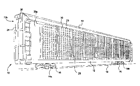
[0017] Fig. 1 is a perspective view of an auto-rack railroad car configured to
transport a plurality of vehicles.
= [0018] Fig. 2 is an exploded front perspective view of the active wheel
chock
of one embodiment of the present disclosure.
[0019] Fig. 2A is front perspective view of the active wheel chock of Fig, 2,
shown with all of its components assembled and including the wheel harness
strap.
[0020] Fig. 3 is a front perspective view of the chock body of the active
wheel
chock of Fig. 2, shown without the rail engager, wheel harness strap, and
wheel
harness strap tensioner components of the active chock.
[0021] Fig. 4 is a rear perspective view of the chock body of the active wheel
chock of Fig. 2, shown without the rail engager, wheel harness strap, and
wheel
harness strap tensioner components of the active chock.
[0022] Fig. 5 is a front (or heel) end view of the chock body of the active
wheel chock of Fig. 2, shown without the rail engager, wheel harness strap,
and
wheel harness strap tensioner components of the active chock.
[0023] Fig. 6 is a rear (or toe) end view of the chock body of the active
wheel
chock of Fig. 2, shown without the rail engager, wheel harness strap, and
wheel
harness strap tensioner components of the active chock.
Date Recue/Date Received 2022-10-19
[0024] Fig. 7 is a right side view of the chock body of the active wheel chock
of Fig. 2, shown without the rail engager, wheel harness strap, and wheel
harness
strap tensioner components of the active chock.
[0025] Fig. 8 is a left side view of the chock body of the active wheel chock
of
Fig. 2, shown without the rail engager, wheel harness strap, and wheel harness
strap tensioner components of the active chock.
[0026] Fig. 9 is a top plan view of the chock body of the active wheel chock
of Fig. 2, shown without the rail engager, wheel harness strap, and wheel
harness
strap tensioner components of the active chock.
[0027] Fig. 10 is a bottom view of the chock body of the active wheel chock
of Fig. 2, shown without the rail engager, wheel harness strap, and wheel
harness
strap tensioner components of the active chock.
[00281 Fig. 11 is a front perspective view of the active wheel chock of Fig.
2,
shown with most of the chock body shown in phantom to better illt.strate the
rail
engager, wheel harness strap, and whee harness strap tensioner components of
the active chock.
r,0029] Fig. 11A is a front perspective view of the active wheel chock of Fig.
2, shown with most of the chock body in phantom, and with the rail engager,
wheel
harness strap, and wheel harness strap tensioner components of the active
chock
removed.
[0030] Fig. 115 is a front perspective view of the ratchet mechanism of the
active wheel chock of Fig. 2, shown removed from the body of the active chock.
[0031] Fig. 12 is a rear perspechve view of the active wheel chock of Fig. 2,
shown with most of the chock body in phantom to better illustrate the rail
engager,
wheel harness strap, and wheel harness strap tensioner components of the
active
chock,
[0032] Fig. 13 is an exploded front perspective view of the anchor wheel
chock of one embodiment of the present disclosure.
[0033] Fig. 14 is a front perspective view of the chock body of the anchor
wheel chock of Fig. 13, shown without the rail engager components of the
anchor
chock.
[0034] Fig. 15 is a rear perspective view of the chock body of the anchor
wheel chock of Fig. 13, shown without the rail engager components of the
anchor
chock.
6
Date Recue/Date Received 2022-10-19
[0035] Fig. 16 is a front (or heel) end view of the chock body of the anchor
wheel chock of Fig. 13, shown without the rail engager components of the
anchor
chock.
[0036] Fig. 17 is a rear (or toe) end view of the chock body of the anchor
wheel chock of Fig. 13, shown without the rail engager components of the
anchor
chock.
[0037] Fig. 18 is a right side view of the chock body of the anchor wheel
chock of Fig. 13, shown without the rail engager components of the anchor
chock.
[0036] Fig. 19 is a left side view of the chock body of the anchor wheel chock
of Fig 13, shown without the rail engager components of the anchor chock.
[0039] Fig. 2C is a top plan view of the chock body of the anchor wheel chock
of Fig. 13, shown without the rail engager components of the anchor chock.
[0040] Fig, 21 is a bottom Vew of the chock body of the anchor wheel chock
of Fig. 13, shown without the rail engager components of the anchor chock.
[0041] Fig. 22 is a front perspective view of the anchor wheel chock of Fig.
13, shown with most of the chock body in phantom to better illustrate the rail
engager components of the anchor chock.
[0042) Fig. 23 is a perspective view of the active wheel chock of Fig. 2 and
the anchor chock of Fig. 13 each shown locked onto a rail on a floor of one of
the
levels in a tri-level auto-rack car and in engagement with a wheel of a
vehicle in an
auto-rack car, wherein said view is taken from the rea- side of the vehicle.
[0043] Fig. 24 is a perspective view of the active wheel chock of Fig. 2 shown
locked onto a rail on a floor of one of the levels in a trl-level atto-rack
car and in
engagement with a rear side of a wheel of a vehicle in an auto-rack car.
100441 Fig, 25 is a perspective view of the anchor wheal chock of Fig. 13
shown locked onto a rail on a floor of one of the levels in a tri-level auto-
rack car
and in engagement with a front side of a wheel of a vehicle in an auto-rack
car.
100451Fig. 25 Is a perspective view of the active wheel chock of Fig. 2 and
the anchor chock of Fig. 13 each shown locked onto a rail on a floor of one of
the
levels in a tri-level auto-racK car and in engagement with a wheel of a
vehicle in an
auto-rack car, wherein said view is taker from the front side of the vehicle.
[0046] Fig. 27 is a sPtie perspective view of the active wheel chock of Fig, 2
and the anchor ctc.)ck of Fig. 13 each shown locked onto a rail on a floor of
one of
7
Date Recue/Da te Received 2022-10-19
the levels in a tri-level auto-rack car and in engagement with a wheel of a
vehicle in
an auto-rack car.
DETAILED DESCRIPTION
[0047] Referring now to the drawings and particularly to Fig. 1, a typical
auto-
rack car 10 includes a frame 12 supported by trucks 14a and 14b, each of which
have several wheels 16 configured to roll along conventional railroad tracks
18.
The frame 12 supports two opposing sidewalls 20a and 20b and a roof 22. The
auto-rack car 10 inc,udes a pair of co-acting clamshell doors 24 and 26
mounted on
each end of the auto-rack car 10. The doors 24 and 26 are opened to facilitate
the.
loading and unloading of vehicles into and out of the auto-rack car 10 and are
closed during transport or storage of the vehicles.
(0048] The sidewalls 20 include a series of steel vertica. posts 28 which are
mounted on, and extend upward y from, the frame 12. The roof 22 is mounted on,
and supported by, these vertical posts. The vertical posts are evenly spaced
along
the entire length of both sidewalls 20 of the auto-rack car 10. A plurality of
rectangular galvanized steel side wall panels 30 which extend horizontally and
are
vertically spaced apart are mounted between each pair of vertical posts 28.
These
side wall panels are supported at their corners by brackets (not shown) that
are
suitably secured to the vertical posts. The average side wall panel has a
multiplicity
of round sidewall panel holes 23. These side wall panel holes 23 provide the
auto-
rack car with natural light as well as proper ventilation. Proper ventilation
prevents
harm from the toxic vehicle fumes to the person or persons (i.e., loaders)
loading or
unloading the vehicles into or out of the auto-rack car.
[0049] The vehicle restraint apparatus of the present disclosure is
particularly
configured for tri-level auto-rack cars having first, second, ard third
levels.
Normally, eighteen passenger vehicles can be transported in a tri-level auto-
rack
car, six on each level. The vehicle restraint apparatus of the present
disclosure can
also be used on a bi-level auto-rack car that has first and second levels or
on a
single-level auto-rack car.
[0050] Each level of the typical tri-level auto-rack car has an elongated rail
50
(which is partly shown in Figs. 23, 24, 25, 26, and 27) fastened to the floor
BO of
that level of the auto-rack car. The rails 50 extend substantially the entire
length of
the auto-rack car 10. The vehicles are loaded on each level with the wheels on
one
8
Date Recue/Date Received 2022-10-19
side of the vehicle (such as wheel 1002) of each vehicle adjacent to the rail
50 as
also partially shown in Figs. 23, 24, 25, 26, and 27. The rail is thus
disposed on
the outside of each of the wheels on one side of each of the vehicles when the
vehicles are loaded in the auto-rack car.
[0051] Referring now to Figs. 2 to 26, one example embodiment of vehicle
restraint apparatus of the present disclosure is illustrated, and includes an
active
wheel chock generally indicated by numeral 100 (fully or partially shown in
Figs. 2,
2A, 3, 4, 5, 6, 7, 8, 9, 10, 11, 11A, 116, 12, 23, 24, 25, 26, and 27), and an
anchor
wheal chock generally indicated by numeral 600 (fully or partially shown in
Figs. 13,
14, 15, 16, 17, 18, 19, 20, 21, 22, 23, 24, 25, 20, and 27). Generally, the
active
wheel chock 100 and the anchor wheel chock 600 each have a heel and a toe. The
heel is configured to be selectively mounted on and locked to the rail 50.
When
mounted, the wheel chocks 100 and 600 each extend substant ally perpendicular
to
the rail 50 with the toe of that chock projecting beneath the vehicle 1000 so
that the
wheel chocks 100 and 600 are disposed in front of and behind the vehicle wheel
002 as shown in Figs. 23, 24, 25, and 26. More specifically, as shown in Figs.
23,
24, 25, 26, and 27, the active wheel chock 100 is configured to be positioned
along
one side of the wheel 1002 of the vehicle 1000, and the anchor wheel chock 600
is
configured to be positioned on the opposite side of the wheel 1002 of the
vehicle
1000. The active wheel chock 100 is configured to be releasably securely
locked to
the rail 50 which is adjacent to the wheel 1002 and which is attached to floor
80 of
the respective level of the auto-rack car 10. The anchor wheel chock 600 is
also
configured to be releasably securely locked to the rail 50 which is adjacent
to the
wheel 1002. The active wheel chock 100 includes a wheel harness strap 400
which
is configured to be paced over and engage the tread 1006 ol the tire 1004 of
the
wheel 1002 and to be releasably attached to the anchor wheel chock 600 as
further
described below. For brevity, the active wheel chock is sometimes referred to
herein as the active chock, and the anchor wheel chock is sometimes referred
to
herein as the anchor chock.
Active Wheel Chock
[0052] More specifically, in this illustrated embodiment as best seen in Figs.
2, 2A, 3, 4, 5, 6, 7, 8, 9, 10, 11, 11A, 116, 12, 23, 24, 25, 25, and 27, the
active
chock 100 includes a chock body 200, a ral engager 300 supported by and
mounted to the chock body 200, a wheel harness strap 400 for engaging the
wheel
9
Date Recue/Date Received 2022-10-19
1002, and a wheel harness strap tensioner 500 supperted by and nnountec to the
chock body 200 and connected to the wheel harness strap 400.
[0053] Turning now first to the non-moving parts of the active wheel chock
100, the chock body 200 includes a heel 202, a toe 204, and an intermediate
section 206 extending between the heel 202 anc the toe 204. The chock body 200
of this illustrated embodiment includes: (a) a substantially diamond shaped
elongated tube which incluces four integrally connected elongated wails 210,
220,
230, and 240; (b) a heel side transversely extending end wall 250 integrally
connected (such as by welding) to the end edges of the heel portions of the
elongated walls 210, 220, 230, and 240; (c) an upside down U-shaped rail
saddle
260 integrally connected (such as by welding) to the elongated walls 210, 220,
230,
and 240: (d) a first transversely extending intermediate wiAl 270 (best seen
in Fig.
11A) positioned in the substantially diamond shaped elongated tube and
integrally
connected (such as by welding) to the inner surfaces of the elongated walls
210,
220, 230, and 240; (e) a second transversely extending intermediate wall 280
(best
seen in Fig. 11A) positioned in the substantially diamond shaped elongated
tube
and integrely connected (such as by welding) to the inner surfaces of the
elongated
walls 210, 220, 230, and 240, and (f) a third transversely extending
intermediate
wall 290 (best seen in Fig. 11A) positioned in the substantially diamond
shaped
elongated tube and integrally connected (such as by welding) to the inner
surfaces
of the elongated walls 210, 220, 230, and 240. It should be appreciated that
these
walls can be connected in other ways and that each of the transversely
extending
walls does not need to be connected each of the elongated walls.
[0054] The elongated walls 210, 220, 230, and 240 of the substantially
diamond shaped elongated tube each have inner and outer surfaces, a heel edge
and a toe edge. More specifically, (a) elongated wall 210 has a tire tread
engaging
outer surface 212, an inner surface, a heel edge, and a toe edge; (b) the
elongated
wall 220 has an outer surface 222, an inner surface, a heel edge, and a toe
edge;
(c) the eongated wall 230 has an outer surface 232, an inner surface, a heel
edge,
and a toe edge; and (d) the elongated wall 240 has an outer surface 242, an
inner
surface, a heel edge, and a toe edge. It should be appreciated that in this
illustrated embodiment, the wai s 210, 220, 230, and 240 have or are
interconnected by curved or rad' us corners in this illustrated embodiment,
but that
the present disclosure is not limited to having such curved or radius corners.
Date Recue/Da te Received 2022-10-19
[0055] The elongated walls 210, 220, 230, and 240 of the substantially
diamond shaped elongated tube define a plurality of cut-outs or openings
which: (a)
provide access to the internal areas of the tube of the chock body 200; (b)
provide
access to the internal components of the active chock 100 for assembly; (c)
enable
parts connected to the internal components of the active chock 100 to extend
outwardly from the elongated tube as further discussed below; and (d) provide
drainage of any water in the chock body 200. More specifically: (a) walls 210
and
220 partially define a first heel opening 221; (b) walls 210 and 220 define an
intermediate section strap opening 223; (c) walls 220 and 230 define a rail
engager
activation lever opening or slot 225: and (d) walls 210, 220, 230, ard 240
define a
rail saddle receiving opening 227.
[0056] The heel end transversely extending end wall 250 is integrally
connected (such as by welding) to the heel edges of the elongated walls 210,
220,
230, and 240. The end wall 250 defines a plurality of cut-outs or openings
which:
(a) provide access to the internal areas of the tube of the chock body 200;
(b)
provide access to the internal components of the active chock 100 for
assembly;
and (c) enable parts connected (such as by welding) to the internal components
of
the active chock 100 to extend outwardly from the tt.be of the chock body 200
as
further discussed below. More specifically, the end wall 250 defines: (a) a
torque
tube assembly receiving opening 253; (b) a strap tension release lever opening
255; and (c) a strap tension release lever attachment fastener opening 257.
The
end wall 250 also supports certain components of the active chock 200 as
further
discussed helm.
[0057) The upside down U-shaped rail saddle 260 is positioned in the rail
saddle receiving opening 227 and is integrally connected (such as by welding)
to
the edges of the elongated walls 20, 220, 230, and 240 that define the rail
saddle
receivIng opening 227. The upside down U-shaped rail saddle 260 includes an
upper wall 262, a first side wall 254, and a second side wall 266, which each
extend
transversely to the tube of the chock body 200, and specifically transversely
to
elongated walls 210, 220, 230, and 240. The upside down U-shaped rail saddle
260 is configured to fit over and rest on the rail 50. Specifically, the upper
wall 262
is configured to ergage the top of the rail 50, the first side wet: 254 is
configured to
extend adjacent to one side of the rail 50, and the second side wall 266 is
configured to extend adjacent to the other side of the rail 50 as generally
shown in
11
Date Recue/Date Received 2022-10-19
Figs. 23, 24, 25, 26, and 27. It should be appreciated that having the upper
wall
262 rest on the rail 50 enables the chock body 200 to be at the lowest point
in the
safe zone,
[0058] The first side wall 264 defines a locking pin receiving opening 265
(best seen in Figs. 11 and 12) and the second side wall 266 defines a locking
pin
receiving opening 267 (best seen in Figs. 11 and 12)-aligned with the locking
pin
receiving opening 265. It should be appreciated that in this example
embodiment,
the locking pin 310 (described below) does not extend into the locking pin
receiving
opening 265, but that in other embodiments, the locking pin can extend into
the
locking pin receiving openirg 265. It should further be appreciated that the
locking
pin receiving opening 265 is formed in the first side wall 264 of the rail
saddle 260
for ease of manufacturing, and specifically to enable the rail saddle 260 to
be
mounted in the elongated tube in either direction.
[0059] The first intermediate wall 270 is positioned approximately midway in
the substantialIy diamond shaped tube of the chock body 100. The first
intermediate wall 270 defines a first torque tube receiving opening 273 (best
seen in
Fig. 11A) aligned with the torque tube assembly receiving opening 253 defined
by
the end wall 250. The first side wall 270 also defines a locking pin receiving
opening 275 (best seen in Figs. 11A and 12) which is aligned with the locking
pin
receiving opening 267 and which is also aligned with the locking pin receiving
opening 265.
[0060] The second intermediate wall 280 is positioned further toward the toe
204 in the substantially diamond shaped tube of the chock body 200 adjacent to
the
heel side of the strap opening 223. The first intermediate wall 280 defines a
torque
tube receiving opening 283 (best seen in Figs. 4 and 11A) aligned with the
torque
tube receiving opening 273 defined by the first intermediate wall 270 and with
the
torque tube assembly receiving opening 253 defined by the end wall 250.
[0061] The third intermediate wall 290 is positioned further toward the toe ir
tee substantially diamond shaped tube cf the chock body 200 adjacent to the
toe
side of the strap opening 223. The third intermediate wall 290 defines a
torque tube
receiving opening 293 (best seer in Figs. 3 and 11A) aligned with the torque
tube
receiving opening 283 defined by the second intermediate wall 280, with the
torque
tube receiving opening 273 defined by the first intermediate wall 270, and
with the
torque tube assembly receiving opening 253 defined by the end wall 250.
12
Date Recue/Date Received 2022-10-19
[0062] In this illustrated embodiment, (a) the aligned openings 253, 273, 283,
and 293 are positioned in and adjacent to the peak or the apex of the
substantially
diamond shaped tube of the chock body 200; and (b) the aligned operings 265,
267, and 275 are positioned in and adjacent to the trough or bottom of the
substantially diamond shaped tube of the chock body 200. The aligned openings
253, 273, 283, and 293 have a central axis which extends in the same vertical
plane or substantially the same vertical plane as the central axis of the
aligned
openings 265, 267, and 275.
[0063] It should be appreciated that the body of the active chock of this
illustrated embodiment of the present disclosure: (a) takes up a smaller area
of the
safe zone adjacent to the wheel than any known commercially available vehicle
restraint; and (b) provides a greater strength to size ratio than the body of
any
known commercially available vehicle restraint. It should also be appreciated
that
the tubular configuration of the body of the active chock provides substantial
rigidity
utilizing relatively thin walls. It should further be appreciated that this
configuration
of the substantially d:amond shaped tube of the chock body of the active chock
has
the greatest height at the point in which it is closest to the tire and then
slopes away
from the tire.
[0064] Turning now to the movable components of the active chock 100 as
best illustrated in Figs. 2, 11, 11A, and 12, the rail engager 300 is
supported by the
chock body 200 and configured to releasably lock the active chock 100 to the
rail
50. The rail engager 300 generally includes a locking in 310 (best shown in
Figs.
2, 11, and 12), an activation lever 320 (best shown in Figs. 2, 2A, 11, and
12)
connected to and extending transversely from the locking pin 310, and a
biasing
member such as coil spring 330 (best shown in Figs. 2, 11, and 12) positioned
about the locking pin 310.
[0065] More specifically, the locking pin 310 is positioned in the
substantially
diamond shaped tube of the chock body 200 in an area adjacent to the trough
and
in the same or substantially the same vertical plane as the apex and trough of
the
substantially diamoad shaped tube of the chock body 200. The locking pin 310
extends through: (a) the locking pin receiving opening 267 of the side wall
266 of
the rail saddle 260; and (b) the locking pin receiving opening 275 of the f
rst
ftermediate wall 270. The locking pin 310 is suppored by the side wall 266 of
the
rail saddle 260 and by the first intermediate wall 270
13
Date Recue/Da te Received 2022-10-19
[0066] The activation lever 320 which is connected to and which extends
transversely from the locking pin 310 includes a stem 322 and a head 324. One
end of the stem 322 extends through the locking pin 310 and the other end of
the
stem is connected to the head 324. In this illustrated embodiment, the end of
the
stem 322 extending though the locking pin 310 has or defines a spring
engagement
notch and the locking pin 310 includes a through hole 312 (best shown in Fig.
2)
configured to receive the end of the stem 322 to facilitate assembly of the
rail
engager 300. The activation lever 320 arid specifically the stem 322 extend
through the rail engager activation lever opening or slot 225.
[0067] The coil spring 330 is positioned or journaled about the locking pin
310 between the stern 322 and the first intermediate wall 270 The ends of the
coil
spring 330 respectvely engage the stem 322 and the wall 270 as shown in Figs.
11
and 12. It should be appreciated that in this configuraticn, the coil spring
330
biases the locking pin 310 away from one of two retracted positions (discussed
below) and toward an extended position (as shown in Fig. 11). In this
illustrated
embodiment, as mentioned above, the locking pin 310 does not extend through
locking pin receiving opening 265 when in the locked position. It should be
appreciated that in other embodiments, the locking pin 310 can extend through
the
locking pin receiving opening 265 in the locked position. In either of the
retracted
positions, the rail engaging end of the locking pin 310 is configured to not
engage
the rail 50 to enable the chock body 200 and the entire active chock 100 to be
placed on the rail 50 or removed from the rail 50. The two retracted positions
include a locked retracted position and an unlocked retracted position. The
rail
engager activation lever opening or slot 225 has a generally sideways L shape
and
includes an upper slot section configured to receive the activation lever 320
and
specifically the stem 322 of the activation lever 320 to prevent the
activation lever
320 from moving toward the heel of the chock body 200. This upper slot section
of
the rail engager activation lever opening or slot 225 thus provides for the
locked
retracted position. When the activation lever 320 is moved downwardly out of
this
upper slot section of the rail engager activation lever opening or slot 225,
the
activation lever 320 is in the unlocked retracted position and wili be biased
by the
coil spring 330 toward the extended position and thus toward the heel 202 and
the
rail locking position. In the
extended or rail locking position, the heel side rail
engaging end of the locking pin 310 is configured to extend through one of the
14
Date Recue/Da te Received 2022-10-19
holes In the rail 50 and lock the chock body 200 and the entire active chock
100 to
the rail 50 as generally shown in Figs. 23 and 24. This configuration provides
a
simple and effective mechanism for locking the active chock 100 onto the rail
50,
[0068] The strap 400 (as best shown in Figs. 2A, 23, 24, 25, 26, and 27)
includes a strap having a body 410 having: (a) central secton 420; (b) a first
end
section 430 configured to be connected to the torque tube 510 of the wheel
harness
strap tensioner 500 as described below; and (c) a second end section 440
connected to an attachment plate 450 which is configured to be releasably and
securely connected to the anchor chock 600, and specifically to the wheel
harness
strap anchor 900 of the ancnor chock 600 as shown in Figs. 25, 26, and 27 and
as
described below. The attachment plate 450 includes a substantially flat body
452
defining a somewhat T shaped slot 454 configured to receive and lock onto the
wheel harness strap anchor 900 extending from the anchor chock 600 as shown in
Figs. 25, 26, and 27 and as described below.
[0069] As best seen in Figs. 2, 2A, 11, 11B, and 12, the wheel harness strap
tensioner 500 generally includes a hollow torque tube 510, a ratchet mechanIsm
530 connected to the torque tube 510, and a release lever 550. The strap 400
is
connected to the torque tube 510 (as best shown in Figs. 2A ard 23) and the
torque
tube 510 is configured to rotate counter-clockwise to wind the strap 400 about
the
torque tube 510. The ratchet mechanism 530 is configured to facilitate the
rotation
of the torque tube 510 to wind the strap about the torque tube 510 which 'n
turn
tightens the strap 400 about the tire 1004 of the wheel 1002. The release
lever 550
is configured to: (a) releasably engage the ratchet mechanism 530 to prevent
undesired clockwise rotation of the ratchet wheel 532 (and thus undesired
rotation
of the torque tube 510 and undesired unwinding of the strap 400) by engaging
(one
or more) of the teeth 531 of the ratchet wheel 532; and (b) disengage and
release
the ratchet mechanism 530 when a user desires to release the tension on the
strap
400 and unwind the strap 400 to reset the strap 400 or to remove the strap 400
and
to remove the active and anchor chocks 100 and 600 from the rail 50 after use
and
before the vehicle is unloaded from the auto-rack car.
[0070] The torque tube 510 longitudinally extends, is supported by, and is
rotatably mounted within the chock body 200, and specifically extends though
aligned openings 253, 273, 280, and 290, is supported by walls 250, 270, 283,
and
293, and is configured to rotate with respect to walls 250, 270, 283, and 293.
In this
Date Recue/Da te Received 2022-10-19
illustrated embodiment, the torque tube 510 and the openings 253, 273, 283,
and
293 extend aiong an upper central axis of the chock body 200 as mentioned
above
In this embodiment, the torque tube 510 extends in an area adjacent to the
apex of
the substantially diamond shaped tube of the chock body 200 and in the same or
substantially the same vertical plane as the apex and trough of the
substantially
diamond shaped tube of the chock body 200. The torque tube 510 includes: (a) a
first end extending toward the toe 204 of the chock body 200 of the active
chock
100; and (b) a second end extending toward the heel 202 of the chock body 200
of
the active chock 100 and connected to the ratchet mechanism 530 as further
discussed beow. The torque tube 510 is also suitably slotted (as best shown in
Figs. 2, 2A, and 11) to enable end 430 of the strap 400 to be threaded through
and
thus attached to the torque tube 510 such that the strap 400 will be: (a)
attached to
the torque tube 510; and (b) wound about the torque tube 510 upon counter-
clockwise rotation of the torque tube 510. It should be appreciated that the
strap
may be attached to the torque tube in other suitable manners in accordance
with
the present disclosure.
[0071] The ratchet mechanism 530 of this illustrated embodiment which is
best shown in Figs. 2, 11, 115, and 12 includes: (a) a first or outer
cylindrical shaft
534; (b) a ratchet wheel 532 attached to the shaft 534; and (c) a second or
inner
cylindrical shaft 536 extending from the first cylindrical or outer shaft 534.
The
ratchet wheel 532 is suitably connected to the first or outer shaft 534 such
that
when the first or outer shaft 534 rotates, the ratchet wheel 532 rotates. The
second
or inner shaft 536 is also suitably connected to the first or outer shaft 534
such that
when the first or outer shaft 534 rotates, the second or inner shaft 536
rotates
[0072] The first or outer shaft 534 includes a heel side first end which is
configured to extend through the openirg 253 in the end wall 250 and to be
rotatably supported by the end wall 250. More specifically, the wheel harness
strap
tensioner 500 includes: (a) an inner washer 540 (best shown in Fig. 2)
positioned
on the first or outer shaft 534 between the toe side surface of the end wall
250 and
the ratchet wheel 532; (b) outer washer 542 (best shown in Figs, 2, 11, and
12)
positioned on the first or outer shaft 534 adjacent to the heel side surface
of the end
wall 250; and (c) a locking or retaining ring 544 (Pest shown in Figs. 2 and
12)
which engages a suitable annular groove 535 (best Shown in Fig. 11B) toward
the
end of the first or outer shaft 534 for locking the first or outer shaft 534
in place
16
Date Recue/Date Received 2022-10-19
while still enabling the first or outer shaft 534 to rotate. The first or
outer shaft 534
also includes a suitable tool engager. More
specifically, in this illustrated
embodiment, the first or outer shaft 534 includes a tool receiving socket 537
(best
shown in Figs. 2A, 11, and 11B) configured to receive a tool (not shown) such
as a
ratchet (not shown) for enabling a user to rotate the ratchet meclanism 530
and
thus rotate the torque tube 510, In this illustrated embodiment, the socket
537 is a
generally square tool receiv ng slot configured to receive the head of a
standard Yz
inch ratchet (not shown).
[0073] The second or inner shaft 536 has a toe side end of a second size
configured to be received in the open heel side end of the torque tube 510 and
to
be secured to the torque tube 510 by a suitable fastener such as locking pin
558
(as best shown in Figs. 2 and 12). This configuration prevents lateral
movement of
the torque tube 510 in the direction toward the toe 204 of the chock body 200
of the
active chock 100. It shou'd be appreciated that in this illustrated
embodiment, the
second or inner shaft 536 has a smaller outer diameter than the first or outer
shaft
534, and that the present disclosure contemplates that the outer diameters of
these
shafts may be the same, or that the second or inner shaft 536 may have a lager
outer diameter than the first or outer shaft 534.
[0074] The re'ease lever 550 (best shown in Figs. 2, 11, and 12) of the wheel
harness strap tensioner 500 includes a pawl 560 configured to engage the teeth
531 of the ratchet wheel 532 to prevent undesired rotation of the torque tube
510
and undesired unwinding of the strap 400. More specifically, the release ever
550
includes a body having: (a) an attachment end 552 which is configured to be
attached to the end wall 250 by a suitable fastener such as locking bolt 580
and nut
582 (best shown in Fig 2); (b) an extending pawl 560 configured to engage the
teeth 531 of the ratchet wheel 532; and (c) an activation arm 556 extend ng
outwardly through opening 255 and configured to be moved by a loader using the
active chock 100. The wheel harness strap tensioner 510 further includes a
suitable spring 590 (best shown in Figs 2, 11, and 12) configured to maintain
:he
release lever 550 and specifically the pawl 560 in the engaged position with
one of
the teeth 531 of the ratchet wheel 532 except when the activation arm 556 is
moved
downwardly oy a loader from the normal or resting up position to a lowe-
release
position, which causes disengagement of the pawl 560 to disengage from any of
the teeth 531 of the ratchet wheel 532. It should be appreciated that he
release
17
Date Recue/Date Received 2022-10-19
lever 550 (and specifically the activation arm 556) is configured such that a
loader
can move the activation arm 556 downwardly with the loader's foot while
pulling the
strap with either one of the loader's free hands.
[0075] It should thus be appreciated from the above that the release lever
550, the shafts 534 and 536, and the ratchet wheel 532 provide a pawl and
ratchet
type mechanism that functions to lock the torque tube 510 against undesired
movement in one direction and particularly against unwinding of the strap 400
as it
is being tensioned and after it is fully tensioned. In this example
embodiment, the
ratchet wheel 532 and the torque tube 510 are: (a) turned counterclockwise to
tension the strap 400; and (b) released in a clockwise fashion to reduce the
tension
on the strap 400. It should be appreciated that in other embodiments, this
configuration can be reversed.
[0076] It should be appreciated from the above that: (a) the locking pin of
the
rail engager extends substantially along a first longitucinal axis extending
through
an area adjacent to a trough of the substantially diamond shaped e ongated
tube of
the chock body of the active chock, (b) the torque tube of the wheel harness
strap
tensional: extends substantially along a second longitudinal axis extending
through
an area adjacent to an apex of the substantially diamond shaped elongated tube
of
the chock body of the active chock; and (c) the first longitudinal axis and
the second
longitudinal axis extend in a vertical or substantially vertical plane and
with the apex
and bottom of the trough of the substantially diamond shaped tube. This
configuration provides for a substantially compact and efficient arrangement
of
these components in the chock body. This configuration also positions the
torque
tube and the strap closer to the tire than any known commercially available
vehicle
restraint apparatus.
[0077] In this il ustrated embodiment, the elongated walls of the
substantially
diamond shaped tubular chock body of the active chock are each made from
steel,
and particularly are integrally formed from a length of tubular steel turned
forty-five
degrees on its side to form the substantially diamcnd shape active chock body.
More specifically, in this illustrated embodiment, the elongated tube of the
active
chock body is initially formed from a substantially square section of tubular
steel
wherein the width of each wall is approximately 3.00 inches, wherein the
height
= from apex to trough is approximately 3.775 inches, wherein the width is
18
Date Recue/Date Received 2022-10-19
approximately 3.775 inches, wherein the thickness of each wall is 11125
inches, and
wherein length is approximately 17.00 inches.
[0076] In this illustrated embodiment, the upside down U-shaped rail saddle
of the chock body of the active chock is made from a section of steel plate.
In one
embodiment, the locking pin receiving openings are formed and then the plate
is
bent to form the side walls. The formed rail saddle is then welded to the
walls of the
elongated tube. The heel side transversely extending end wall and the
transversely
extending intermediate walls are made from steel plates and welced to the
walls
which define the elongated tube of the chock body. This configuration and
method
of manufacture provides the chock body with additional substantial strength.
It
should be appreciated that the transversely extending walls add structural
rigidity to
the chock body (for both active and anchor chocks). It should also be
appreciated
that additional transversely extending walls or other structural supports can
be
added to the chock bodies.
[00791 It should be appreciated that the chock body of the active chock can
be made from other suitable materials and in other suitable manners in
accordance
with the present disclosure. For example, the chock body can be made from a
molded plastic material having sufficiently strong impact strength over a wide
range
of temperatures normally encountered by auto-rack cars. It should also be
appreciated that in certain alternative embodiments the chock body of the
active
chock can be formed in other suitable shapes that provide the same or
substantially
the same advantages of the substantially diamond shaped chock body. For
example, in alternative embodiments, the chock body has a round, oval or
triangular configuration.
[0080] In this illustrated embodiment, the locking pin is made from steel, the
activation lever is made from steel, and the coil spring is also made from
steel.
However, it should be appreciated one or more of these components can be made
from other suitable materials.
{0081] in this illustrated embodiment, the torque tube, the ratchet
mechanism, and the release lever are also made from steel. However, it should
be
apprecrated one or more of these components can be made from other suitable
materials.
19
Date Recue/Date Received 2022-10-19
[0082) In this illustrated embodiment, the anchor plate of the strap is made
from steel. However, it should be appreciated that this component can be made
from other suitable materials.
[0083] In this illustrated embodiment, the strap body is made from a suitable
woven fabric such as nylon having an acceptable strength. For example, in
certain
embodiment, the strap is made of material smiler to that used in seatbelts for
automobiles and airplanes. It should be appreciated that The strap body can be
made from alternative materials in accordance with the present disclosure. It
should
also be appreciated that other suitable type tire engaging straps may be
employed
in the vehicle restraint apparatus of the present disclosure. For example, in
certain
alternative embodiments, the strap includes a harness with multiple sections
(not
shown) which are configured to engage the tire of the wheel. In other example
alternative embodiments, the strap includes a plurality of spaced apart tire-
engaging blocks (not shown) which include one or more longitudinally extending
ribs (not shown) projecting from the underside for engagement to or in the
treads
1006 of the tire 1004 to inhibit lateral movement of the strap along the
treads 1006
of the tire 1004. The blocks may be made of a suitable resilient material such
as
natural or synthetic rubber or any other type of plastic that would enhance
the
fnctional engagement desired when in contact with a tire of the wheel.
[0084) It should further be appreciated that the rail engager and the wheel
harness strap tensioner of the active chock can be alternatively configured or
can
include different components or different arrangements of components than
described above in accordance with the oresent disclosure.
Anchor Wheel Chock
[0085] More specifically, in this illustrated embodiment as best seen in Figs.
13, 14, 15, 16, 17, 18, 19, 20, 21, 22, 23, 24, 25, 26, and 27, the anchor
chock 600
includes a chock body 700, a rail engager 800 mounted to the chock body 600, a
wheel harness strap anchor 900 extending from the chock body 700,
[0086] Turning now first to the non-movable parts of the anchor wheel chock
100, the chock body 700 includes a heel 702, a toe 704, and an intermediate
section 706 extending between the heel 702 and the toe 704. The chock body 700
includes: (a) a substantially diamona shaped elongated tube which includes
four
integrally connected elongated wiEdls 710, 720, 730, and 740; (b) a heel side
Date Recue/Date Received 2022-10-19
transversely extending end wall 750 integrally connected (such as by welding)
to
the heel side ends of the elongated walls 710, 720, 730, and 740; (c) an
upside
down U-shaped rail saddle 760 integrally connected (such as by welding) to the
elongated walls 713, 720, 730, and 740; and (d) a first transversely extending
intermediate wall 770 (best seen in Fig. 22) positioned in the substantially
diamond
shaped elongated tube and integrally connected (such as by welding) to the
inner
surfaces of the elongated walls 710, 720, 730, and 740. It should be
appreciated
that wall 770 can be connected in other ways and that this transversely
extending
wall does not need to be connected to each of the elongated wafts 710, 720,
730,
and 740.
[0057] The elongated walls 710, 720, 730, and 740 of the substantially
diamond shaped elongated tube each have inner and outer surfaces, a heel edge
and a toe edge. More specifically, (a) elongated wall 710 has a tire tread
engaging
outer surface 712, an inner surface, a heel edge, and a toe edge; (b) the
elongated
wall 720 has an outer surface 722, an inner surface, a heel edge, and a toe
edge;
(c) the elongated wail 730 has an outer surface 732, an inner surface, a heel
edge,
and a toe edge; and (d) the elongated wall 740 has an outer surface 742, an
inner
surface, a heel edge, and a toe edge. It should be appreciated that in this
illustrated embodiment the walls 710, 72C, 730, and 740 have or are
interconnected
by curved or radius corners in This illustrated embodiment, but that the
present
disclosure is not limited to having such curved or radius corners.
[0088] The elongated walls 710, 720, 730. and 740 of the substantially
diamond shaped elongated tube define a plurality of cut-outs or openings
which: (a)
provide access to the internal areas of the tube of the chock body 700; (b)
provide
access to the internal components of the anchor chock 600 for assembly; (c)
enable
parts connected to the internal components of the anchor chock 600 to extend
outwardly from the tube as further discussed below; and (d) provide drainage
for
any water in the chock body 700. More specifically: (a) walls 720 and 730
define a
rail engager activation lever opening or slot 725; and (b) walls 710, 720,
730, and
740 define a rail saddle receiving opening 727.
[0089] The heel side transversely extending end wall 750 is integrally
connected (such as by welding) to the heel edges of the elongated walls 710,
720,
730, and 740: The end wall 750 defines a plurality of cut-outs or openings
which:
(a) provide access to the internal areas of the tube; and (b) provide access
to the
21
Date Recue/Date Received 2022-10-19
internal components of the anchor chock 600 for assembly. More specifically,
in
this illustrated embodiment, the end wall 75C defines: (a) an access opening
753
(as best shown in Figs. 14 and 16) for providing access to the interior
section of the
chock body 700; and (b) a drainage opening 755 (as also best shown in Figs. 14
and 16) for facilitating drainage of any water which enters the chock body
700. It
should be appreciated that while the end wall 750 adds extra strength to the
chock
body 700, the present disclosure contemplates that the end wall 750 can be
removed from the chock body 700.
[0090] The upside down U-shaped rail saddle 760 is positioned in the rail
saddle receiving opening 727 and is integrally connected (such as by welding)
to
the edges of the elongated walls 710, 720, 730, and 740 that define the rail
saddle
receiving opening 727. The upside down U-shaped rail saddle 760 includes an
upper wall 762, a first side wall 764, and a second side wall 766, which each
extend
transversely to the tubular body and specifically transversely to the
elongated walls
710, 720, 730, and 740 of tne tubular body. The upside down U-shaped rail
saddle
760 is configured lc fit over and rest on :he rail 50. Specifically, the upper
wall 762
is configured to engage the top of the rail 50, the first side wall 764 is
configured to
extend adjacent to one side of the rail 50, and the second side wall 766 is
configured to extend on the other side of the rail 50 as illustrated in Figs.
25 and 26.
It should be appreciated that having the upper wall 762 rest on the rail 50
enables
the chock body 700 to be at the lowest point in the safe zone adjacent to the
wheel.
[0091] The first side wall 764 defines a locking pin receiving opening 765,
and the second side wall 766 defines a locking pin receiving opening 767
aligned
with the locking pin receiving opening 765 (as best shown by Fig. 22). It
should be
appreciated that in this example embodiment, the locking pin 810 (described
below)
does not extend into the locking pin receiving opening 765, but that in other
embodiments, the locking pin can extend into the locking pin receiving opening
765.
It should further be appreciated that the locking pin receiving opening 765 is
formed
in the first side wall 764 of the rail saddle 760 for ease of manufacturing,
and
specifically to enable the rail saddle 760 to be mounted in the elongated tube
in
either direction.
(00921 The first intermediate wall 770 is positioned approximately midway in
the substantially diamond shaped tube (as best shown in Fig 22). The first
intermediate wall 770 defines a locking pin receiving opening 775 which is
aligned
22
Date Recue/Date Received 2022-10-19
with the locking pin receiving opening 767 and aligned with the locking pin
receiving
opening 765.
[0093] In this illustrated embodiment, the aligned openings 765, 767, and
775 are positioned in and adjacent to the trough or bottom of the
substantially
diamond shaped tube of the chock body 700.
[0094] The wheel harness strap anchor 900 extends transversely from the
chock body 700. The wheel harness strap anchor 900 includes a head 910 and a
neck 920 having a first end attached to the head 910 and a second end attached
to
the body and specifically to walls 720 and 730. It should be appreciated that
the
anchor can be integrally connected (such as by welding) to one or more of
these
walls or connected in other suitable manners.
100951 It should be appreciated that the body of the anchor chock of this
illustrated embodiment of the presen: disclosure: (a) takes up a smaller area
of the
safe zone adjacent to the wheel than any known commercially available vehicle
restraint; and (b) provides a greater strength to size ratio than the body of
any
known commercially available vehicle restraint. It should also be appreciated
that
the tubular configuration cf the body of the anchor chock provides substantial
rigidity utilizing relatively thin walls. It should further be appreciated
that this
configuration of the substantially diamond shaped tube of the chock body of
the
anchor chock has the greatest height at the point in which it is closest to
the tire and
then slopes away from the tire.
[0098] Turning now to the movable components of the anchor chock 600, as
illustrated in Figs. 13 and 22, the rail engager 800 is supported by the chock
body
700 and configured to releasably lock the anchor chock 600 to the rail 50. The
rail
engager 800 generally 'ncludes a locking pin 810, an activation lever 820
connected to and extending transversely from the locking pin 810, and a
biasing
member such as coil spring 830 positioned about the locking pin 810.
[0097] More specifically, the locking pin 810 is positioned in the
substantially
diamond shaped tube of the chock body 700 in an area adjacent to the trough
and
in the same or substantially the same vertical plane as the apex and trough of
the
substantially diamond shaped tube of the chock body 700. The locking pin 810
extends through: (a) the locking pin receiving opening 767 of the side wall
766 of
:he rail sadcle 760, and (b) the locking pin receiving opening 775 of the
first
23
Date Recue/Da te Received 2022-10-19
intermediate wall 770. The locking pin 810 is supported by the side wall 766
of the
rail saddle 760 and the first intermediate wall 770,
[0098] The activation lever 820 which is connected to and which extends
transversely from the locking pin 810 indudes a stem 822 and a head 824. One
end of the stem 822 extends through the locking pin 810 and the other end of
the
stem 822 is connected to the head 824. In one embodiment, the end of the stem
822 extending through the !ockirg pin 810 has or defines a spring engagement
notch and the locking pin 810 includes a through hole 812 configured to
receive the
end of the stem 822 to facilitate assembly of the rail engager 800. The
activation
lever 820 and specifically the stem 822 extend through the rai engager
activation
lever opening 725.
100991 The coil spring 830 is positioned or journaled about the locking pin
810 between the stem 822 and the first intermediate wall 770. The ends of the
coil
spring 830 respectively engage the stem 822 and the wall 870 as shown in Fig.
22
It should be appreciated that in this configuration, the coil spring 830
biases the
looking pin 610 away from one of two retracted positions (discussed below) and
toward an extended position (as shown in Fig. 22). In this illustrated
embodiment,
as mentioned above, the locking pin 810 does not extend through locking pin
receiving opening 765 when in the locked position. It should be appreciated
that in
other embodiments, the locking pin 810 can extend through the locking pin
receiving opening 765 in the locked position. In either of the retracted
positions, the
rail engaging end of the locking pin 810 is configured to engage the rail 50
to
enable the chock body 700 and the entire active chock 600 to be placed on the
rail
50 or removed from the rail 50. The two retracted positions include a locked
retractec position and an unlocked retracted position. The rail engager 800
activation lever opening 725 has a generally sideways I shape and includes an
upper slot section configured to receive the activation lever 820, and
specifically the
stem 822 of the activation lever 820, to prevent the activation lever 820 from
moving toward the heel of the chock body 700. This upper slot section of the
opening 725 this provides for the locked retracted position. When the
activation
lever 320 is moved downwardly out of this upper slot section, the activation
lever
820 is in the unlocked retracted Position and will be biased by the coil
spring 830
toward the extended position and thus toward the heel 702 and the rail lockng
position. In the extended or rail locking position, the heel side rail
engaging end of
24
Date Recue/Date Received 2022-10-19
the locking pin 810 is configured to extend through one of the holes in the
rail 50
and lock the chock body 700 and the entire anchor chock 600 to the rail 50 as
generally shown in Figs. 25 and 26. This configuration provides a simple and
effective mechanism for locking the anchor chock 600 onto the rail 50.
[00100] It should be appreciated from the above that: (a) the
locking pin
of the rail engager extends in the elongated tube substantially along a first
longitudinal axis extending through an area adjacent to a trough of the
substantially
diamond shaped elongated tube of the chock body of the anchor chock; and (b)
the
f rst longitudinal axis extends in a vertical or substantially vertical plane
and with the
apex of and bottom of the trough of the substantially diamond shaped tube.
This
configuration provides for a substantially compact arid efficient arrangement
of
these components in the chock body.
[00101] in this illustrated embodiment, the elongated walls of the
substantially diamond shaped tubular chock body a' the anchor chock are each
made 'From steel, and particularly are integrally formed from a length of
tubular steel
turned forty-five degrees on its side to form the substantially diamond shape.
More
specifically, in this embodiment, the elongated tube of the anchor chock body
is
initially formed from a substantially square section of tubular steel wherein
the width
of each wall is approximately 3.00 inches, wherein the height from apex to
trough is
approximately 3.775 inches, wherein the width is approximately 3.775 inches,
wherein the thickness of each wall is 0.125 inches, and wnerein length is
approximately 17.00 inches.
[00102] In this illustrated embodiment, the upside down U-shaped
rail
saddle of the chock body of the anchor chock is made from a section of steel
plate.
In one embodiment, the locking pin receiving openings are formed and then the
plate is bent to form the side walls. The formed rail saddle is then welded to
the
walls of the elongated tube. The heel side transversely extending end wall and
the
transversely extending intermediate wall are made from steel plates and welded
to
the walls which define the elongated tube of the chock body. This
configuration and
method of manufacture provides the anchor chock body with additional
substantial
strength. It should be appreciated that the transversely extending walls add
structural rigidity to the chock body (for both active and anchor chocks). It
should
a:so be appreciated that additional transversely extending walls or other
structural
supports can be added to the chock body.
Date Recue/Da te Received 2022-10-19
[00103] It should be appreciated that the chock body of the anchor
chock can be made from other suitable materials and in other suitable manners
in
accordance with the present disclosure. For example, trio chock body can be
made
from a molded plastic material having sufficiently strong impact strength over
a wide
range of temperatures normally encountered by auto-rack cars. It should also
be
appreciated that in certain alternative embodiments the chock body of the
anchor
chock can be formed in other suitable shapes that provide the same or
substantially
the same advantages of the substantially diamond shaped chock body. For
example, in alternative embodiments, the chock body has a round, oval, or
triangular configuration.
[00104] In this illustrated embodiment, the wheel harness strap
anchor is
made from steel. However, it should be appreciated that this component can be
made from other suitable materials.
[00105] In this illustrated embodiment, the locking pin is made
from
steel, the activation lever is made from steel, and the coil spring is also
made from
steel. However, it should be appreciated one or more of these components can
be
made from other sJitable materials.
[001061 It should further be appreciated that the rail engager of
the
anchor chock can be alternatively configured or can include different
components or
different arrangements of components than described above in accordance with
the
present disciosure.
Operation of Vehicle Restraint Apparatus
[00107] To employ the active and anchor chocks of the present
disclosure, after the vehicle 1000 is positioned in the auto-rack car 10, the
loader
places: (a) the anchor chock 600 on one side of the wheel 1002 and locks the
anchor chock on the rail 50; and (b) the active chock 100 on the other side of
the
wheel 1002 and locks the active chock on the rail 50, as generally illustrated
by
Figs. 23, 24, 25, 26, and 27. The loader then drapes the strap 400 over the
tire
1004 of the wheel 1002 and connects the anchor plate 450 to the anchor 900 of
the
anchor chock 700. The loader Vier' rotates the strap tensioner 500, and
specifically
the ratchet mechanism counterclockwise to tighten the strap 400 on the tire
1004 of
the wheel 1002. It should be appreciated that. (a) in Figs. 23, 24, 25, 26,
and 27,
the anchor chock 600 is positioned adjacent to the front side of the wheel
1002 and
26
Date Recue/Date Received 2022-10-19
the active chock 100 is positioned adjacent to the rear side of the wheel
1002, and
(b) the vehicle can be driven into the auto-rack car in the opposite direction
and that
in such case, the anchor chock 600 is positioned adjacent to the rear side of
the
wheel and the active chock 100 is positioned adjacent to the front side of the
wheel.
[00108] To remove the active and anchor chocks, the loader
activates
the release arm 556 of the lever 550 to release the pawl 560 from the teeth of
the
ratchet wheel 532 which enables the torque tuber 510 to rotate clockwise and
remove the tension on the strap 400. The anchor plate 450 is then removed from
the anchor 900. The active and anchor chocks are then each unlocked from the
rail
50 and removed from their respective positions in front of and behind the
wheel
1002,
Reverse Configuration of the Active and Anchor Chocks
[001091 The above example embodiment of the present disclosure
includes an active chock and anchor chock where: (a) the active chock is
configured to be positioned on the right side of the anchor chock; and (b) the
anchor chock is configured to be positioned on the left side of the active
chock, as
shown in Figs. 23, 24, 25, 26, and 27. It should be appreciated that in
alternative
embodiments of the present disclosure (a) the active chock is configured to be
positioned on the left side of the anchor chock, and (b) the anchor chock is
configured to be positioned on the right side of the active chock. In such
embodiments, each of the active chock and the anchor chock would be in a
reverse
configuration. For example, in such a reverse configuration, (a) when looking
from
the heel end of the anchor chock, the anchor 900 and the locking pin
activation
lever 820 of the anchor chock would extend from the right side of the chock
body
700 (instead of the left side), and (b) when looking from the heel end of the
active
chock, the locking pin activation 'ever 320 of the active chock would extend
from
the left side of the chock body 200 (instead of the right side). In this
reverse
configuration the torque tube would rotate clockwise to tighten the strap and
counterclockwise to loosen the strap,
27
Date Recue/Da te Received 2022-10-19
Vehice Restraint Apparatus Having Multiple Active Chocks
[00110j Tne above
example embodiment of the present disclosure
include an active chock and anchor chock where the active chock has a strap
tensioner and the anchor chock does not have a strap tensioner. It should be
appreciated that in alternative embodiments of the present disclosure, both of
the
chocks employed are active chocks with strap tensioners, in certain such
embodiments, one or more connectors (not shown) may be employed for
connecting the stra3s or strap ends.
Safe Zone
[00111] It should also
be appreciated that each of the active and anchor
chocks of the present disclosure operate in smaller areas of the safe zones in
front
of and behind each wheel than any known commercially available chock or
vehicle
restraint system.
Other Alternative Embodiments
(001121 In various
alternative embodiments, the end plate 250 extends
downwardly or includes a downwardly extending footer (not shown) which is
configured to rest on the floor of the auto-rack railroad car adjacent to the
rail to
provide extra support for the chock body of the active chock. In other
embodiments, the footer (not shown) extends downwardly from the heel end of
the
tube of the chock body of the active chock.
[00113] In various
alternative embodiments, the end plate 750 extends
downwardly or includes a downwardly extending footer (not shown) which is
configured to rest on the floor of the auto-rack railroad car adjacent to the
rail to
provide extra support for the chock body of the anchor chock. In other
embodiments, the footer (not shown) extends downwardly from the heel end of
the
tube of the chock body of the anchor check.
[00114] In various
alternative embodiments, an end plate (not shown) is
mounted to the toe end of the chock body of the active chock. In other various
alternative embodiments, an end cap (not shown) is mounted to the edges of the
toe end of the chock body of the active chock. In various embodiments, the end
cap is made from a suitable rubber material or a suitable plastic material.
28
Date Recue/Date Received 2022-10-19
[00115] In various alternative embodiments, an eno plate (not
shown) :s
mounted to the toe end of the chock body of the anchor chock. In other various
alternative embodiments, an end cap (not shown) is mounted to tne edges of the
toe end of the chock body of the anchor chock. In various embodiments, the end
cap is made from a suitable rubber material or a suitable plastic material.
[00116] In certain such embodiments, the chock body of the active
chock also includes a dowrwardly extending footer (not shown) which is
configured
to rest on the floor o' the auto-rack railroad car and which is spaced from
the rail to
provide extra support for the chock body of the active chock.
[00117] In certain such embodiments, the chock body of the anchor
chock also includes a downwardly extending footer (not shown) which is
configured
to rest on the floor of the auto-rack railroad car and which is spaced from
the rail to
provide extra support for the chock body of the anchor cnock.
[00118] In various alternative embodiments; the anchor chock is
made
without the end plate 750. In other various alternative embodiments, the end
plate
750 has a different configuration or different openings.
[00119] In various alternative embodiments, the active chock
includes
one or more handles (not shown) attached to the chock body which enables the
active chock to be more easily carried and moved. In various alternative
embodiments, the active chock includes one or more openings in the chock body
which enables the active chock to be more easily carried and moved.
[00120] In various alternative embodiments, the anchor chock
includes
one or more handles (not shown) attached to the chock body which enables the
anchor chock to be more easily carried and moved. In various alternative
embodiments, the anchor chock includes one or more openings in the chock body
which enables the anchor chock to be more easily carried and moved.
[00121] It should be understood that modifications and variations
may be
effected without departing from the scope of the novel concepts of the present
invention, and it shouid be understood that this application is to be limited
only by
the scope of the claims.
29
Date Recue/Date Received 2022-10-19