Note: Descriptions are shown in the official language in which they were submitted.
CA 03182100 2022-11-01
WO 2021/257410
PCT/US2021/037116
CRASH IMPACT ATTENUATOR SYSTEMS AND METHODS
Background of the Invention
The present invention relates generally to crash impact attenuators, and
more particularly to motor vehicle and highway barrier crash impact
attenuators
comprising fixed systems protecting leading edges of abutments and other fixed
roadside hazards.
Vehicular accidents on the highway are a major worldwide problem and are
undoubtedly one of the largest causes of economic and human loss and suffering
inflicted on the developed world today. In an effort to alleviate, in
particular, the
human toll of these tragic accidents, guardrails, crash cushions, truck-
mounted
crash attenuators, crash barrels, and the like have been developed to
attenuate the
impact of the vehicle with a rigid immovable obstacle, such as a bridge
abutment.
A crash attenuator of the type described must absorb the vehicle impact
energy without exceeding limits on the vehicle deceleration. In addition, it
must
accommodate both heavy and light weight vehicles. The lightest vehicle will
set
the limit on the maximum force produced by the attenuator and the heavy
vehicle -
which will experience a lower deceleration, and thus will determine the total
impact
deformation required. When impacted head-on, crash attenuators/cushions are
designed to absorb energy and to gradually slow the vehicle to a controlled
stop.
The force cannot exceed the light vehicle limit and therefore the initial
force and
deceleration is low, limiting the energy absorption. Increasing crash
resistance as
the vehicle "rides down" from its impact speed to zero is a vitally important
feature
of a crash attenuator system which meets rigid governmental safety standards.
When impacted obliquely on its side, a crash cushion is designed to redirect
the
vehicle back toward the roadway and to prevent severe impact with the rigid
point
hazard. Typical crash cushions incorporate side rails/panels, intermediate
1
CA 03182100 2022-11-01
WO 2021/257410
PCT/US2021/037116
diaphragms, a track assembly to anchor and guide the intermediate diaphragms,
and
energy absorbers. As crash safety standards have evolved to higher and higher
requirements in order to better protect vehicle occupants from injury, it has
become
clear that new generation crash impact attenuators, or crash cushions, are
required
to perform this function and meet these high standards in innovative,
inexpensive,
and very simple, but effective, manners. The present invention meets and
exceeds
these high standards.
The invention, together with additional features and advantages thereof,
may best be understood by reference to the following description taken in
conjunction with the accompanying illustrative drawing.
Summary of the Invention
The present invention is particularly innovative, in that the side panels
disposed thereon also serve as the energy absorbers, so that there is no need
for
additional interior absorber components. This approach, which reduces system
complexity and cost, has not been utilized in previous crash cushion
technology.
The side panels of the new crash impact attenuator system are designed to
slide over or telescope over each other as the crash attenuator system is
compressed
end-on. This is a common feature of crash cushions. However, the attachment
bolts at the downstream end of each panel are intended to tear through the
side
panels/rails as the panel moves past the attachment bolt. This tearing
behavior
absorbs energy as the system is compressed and the errant vehicle is brought
to a
controlled, safe stop prior to impacting the rigid hazard. The resistance
forces in
the panels are controlled to absorb energy at a prescribed rate as the
attenuator
compresses. The resistance forces are designed to be low initially, but to
increase
along the overall length of the system. Forces can differ between panels and
even
within individual panel segments. Variations in the resistance force are
achieved
through several novel concepts, such as varying panel thicknesses and the
2
CA 03182100 2022-11-01
WO 2021/257410
PCT/US2021/037116
introduction of holes configured with various shapes that are cut into the
panels
along the tearing path. Utilization of different shapes and spacings between
shapes
not only affects the resistance forces, but also helps to control the
consistency of
the tear path and can be used to achieve different fracture modes (e.g. Mode 1
-
tensile failure, Mode II ¨ shear failure, Mode III ¨ out-of-plane shear, or a
combination of these failure mechanisms). Further, some hole shapes can be
used
to reduce debris. Perforations may also be used to control resistance forces
and
tearing path. For panels with higher resistances, the holes or cutouts can be
staggered to mitigate force spikes during the impact event. Subsequently,
panels
can be configured for multiple forces and for multiple impact conditions.
The structure of an exemplary embodiment of the crash cushion is
configured with a dual track design having two T-shaped track-rails, which
anchor
and guide the intermediate diaphragms. The track rails are welded to
intermittent
base plates that are anchored to the pavement. The intermediate diaphragms and
impact head are assembled from structural steel tubes and equipped with feet
that
slide along the guide track. The feet on the impact head are elongated to
prevent/limit rotations of the impact head about the vertical and lateral axes
during
off-centered/angle impacts and high bumper impacts on the nose of the device,
respectively. The intermediate diaphragm feet are also designed to limit
rotations.
Both the impact head and the intermediate diaphragms are designed with
sufficient
lateral strength capacity to withstand vehicle impacts to the side of the
crash
cushion. Attachment bolts between the panels and the intermediate
diaphragms/impact head are configured with a specially designed, integrated
washer plate to allow the panels to slide over each other, guide the tearing
path
along the panels, and prevent the attachment bolts from pulling through the
side
panels. Also, the crash cushion is equipped with a crushable energy absorbing
nose piece that prolongs momentum transfer and elongates the inertial pulse as
the
impact head and side panels begin to move at the start of an impact event.
This
feature reduces peak forces imparted to the vehicle and its occupants.
3
CA 03182100 2022-11-01
WO 2021/257410
PCT/US2021/037116
More particularly, in one aspect of the invention there is provided a crash
impact attenuator system for mitigating a direct vehicular impact with a fixed
structure, comprising an attenuator portion comprising a plurality of
supporting
members. The fixed structure may comprise, for example, concrete abutments,
guardrail systems, terminal and guardrail end treatments, and the like. In the
case
of guardrails, for example, the supporting members may simply be support
posts.
The attenuator system further includes a side panel comprising one of a
plurality of
side panels disposed along a side of the attenuator portion, the side panel
being
adapted to slide rearwardly along the attenuator portion when the crash impact
attenuator system is impacted by a vehicle so that the side panel slides over
a
second adjacent one of the plurality of side panels as it slides rearwardly
responsive
to a vehicular impact. Each of the plurality of side panels includes a
plurality of
holes disposed in material comprising that particular side panel, the
plurality of
holes extending along a length of each of the plurality of side panels and
being
spaced lengthwise from one another.
Advantageously, a tearing member is disposed on the attenuator portion,
which is adapted to engage one of the plurality of holes in the side panel
material.
Thus, when the crash attenuator is impacted by a vehicle, relative motion
occurs
between the side panel and the tearing member, thereby tearing a fracture or
slit in
the material forming the side panel which extends between adjacent ones of the
plurality of holes. This tearing of the side panel material attenuates the
impact
force. The side panel material is tuned to optimize the tearing of the side
panel
material, the tuning of the side panel material being accomplished by sizing
and
arranging the plurality of holes in a predetermined manner.
In illustrated embodiments of the invention, the attenuator portion further
comprises a rail extending along a length of the crash attenuator system. In
such
embodiments, the plurality of supporting members may comprise a plurality of
diaphragms disposed in spaced relation along the length of the rail, each of
the
plurality of diaphragms having a base end or foot adapted to be movably
engaged
4
CA 03182100 2022-11-01
WO 2021/257410
PCT/US2021/037116
with the rail, so that when the crash impact attenuator system receives an
impact
force from an impacting vehicle, a first one of the plurality of diaphragms
moves
rearwardly along the rail and impacts a second one of the plurality of
diaphragms,
wherein both the first and second ones of the plurality of diaphragms move
further
rearwardly along the rail, this process continuing with additional ones of the
plurality of diaphragms until the impact forces have been fully attenuated. In
the
illustrated embodiments, the side panels are also known as fender panels, as
is
typically the case for constructing crash cushions of the type shown and
described.
In illustrated embodiments, the tearing member comprises a bolt, and is
disposed on one of the plurality of diaphragms. The tearing member preferably
comprises a plurality of tearing members, for greater attenuating effect.
Another advantageous feature of the present invention is the ability to tune
the side panels for optimal attenuation. For example, the holes, in certain
embodiments, are not evenly spaced along the length of the side panel.
Adjacent
ones of the plurality of holes nearer to a first or rear (rightmost, in the
illustrated
embodiments) end of the side panel may be more closely spaced than adjacent
ones
of the plurality of holes closer to a second or front (leftmost, in the
illustrated
embodiments) end of the side panel. The plurality of holes may not be uniform
in
size, respective to one another. Rearmost ones of the plurality of holes may
be
larger and more elongated than those of the plurality of holes which are
located
closer to the front end of the side panel. The material forming the side panel
may
be thinner toward the rear end of the side panel, and thicker toward the front
end of
the side panel. In some embodiments, the plurality of holes may be arranged to
form first and second rows of holes spaced from one another along a height of
the
side panel, wherein corresponding ones of the holes forming each of the first
and
second rows of holes on the side panel are aligned lengthwise with one
another. In
other multi-row embodiments of this type, corresponding ones of the holes
forming
each of the first and second rows of holes on the side panel are staggered
lengthwise from one another.
5
CA 03182100 2022-11-01
WO 2021/257410
PCT/US2021/037116
In illustrated embodiments, the side panel comprises a first stage attenuator
portion and the second side panel comprises a second stage attenuator portion,
the
first stage attenuator portion being in front of the second stage attenuator
portion
and the side panel, which is in an earlier stage, being softer than the second
side
panel, which is in a later stage, rearward of the earlier stage. The side
panel is
tuned to be softer than the second side panel because of one or more of the
following: a) the side panel has a greater number of holes than the second
side
panel, b) an average size of the holes in the second side panel is smaller
than an
average size of the holes in the side panel, c) some or all of the holes in
the side
panel are differently shaped than some or all of the holes in the second side
panel,
d) spacings between holes in the second side panel are larger than spacings
between
holes in the side panel, and e) an average thickness of the side panel is less
than an
average thickness of the second side panel.
By way of example, the plurality of side panels may further comprise third,
fourth, and fifth side panels extending lengthwise rearwardly of the second
side
panel, wherein the third side panel comprises a third stage attenuator
portion, the
fourth side panel comprises a fourth stage attenuator portion, and the fifth
side
panel comprises a fifth stage attenuator portion, wherein the third side panel
is
stiffer than the second side panel, the fourth side panel is stiffer than the
third side
panel, and the fifth side panel is stiffer than the fourth side panel. Thus,
sequentially from the first through the fifth stages, each successive side
panel may
be adapted and constructed to be stiffer than the prior-stage side panel. It
should
be noted that, in some embodiments, identical panels may be used for
successive
stages, so in such a case, each successive side panel is equal to or greater
in
stiffness/resistance than the previous side panel going in a rearward
direction. Of
course, a total of five stages is exemplary or illustrative only, as any
number of
stages may be employed within the parameters of the inventive concept. A nose
box is typically disposed at the frontmost end of the crash attenuator, in
each of the
foregoing embodiments. Definitionally, "soft" means that the panel or material
6
CA 03182100 2022-11-01
WO 2021/257410
PCT/US2021/037116
will provide less force resistance or less energy absorption per unit
displacement,
while a "stiff' panel or material will provide more force resistance or more
energy
absorption per unit displacement relative to a soft panel.
An advantageous feature of the invention is that the bolt may be assembled
together with a bent washer plate. The bent washer plate comprises a flared
front
wing. The limited front extension of the bent washer plate allows curling of
the
side panel and prevents buildup as the side panel is being torn by the bolt.
The plurality of holes extending along the length of each of the plurality of
side panels, and being spaced lengthwise from one another, may advantageously
comprise a row of holes on each of the plurality of side panels, the row of
holes
extending lengthwise along each of the plurality of side panels terminating
before
reaching a front end of each of the plurality of side panels. This termination
of the
row of holes in each of the plurality of side panels facilitates initiation of
shearing
in a next adjacent one of the plurality of side panels, thereby reducing
spikes in
attenuation of the impact force as the crash impact attenuator system is
compressed.
Another advantageous feature of the invention is that the rail comprises first
and second rails disposed in parallel to one another and extending along a
length of
the attenuator portion, each of the first and second rails having a T-shaped
configuration, including a top flange disposed horizontally and extending
along a
length of each rail. The base end or foot of each of the plurality of
diaphragms
comprises first and second base ends or feet, the first foot being configured
to wrap
around the top flange of the first rail and the second foot being configured
to wrap
around the top flange of the second rail. This permits lateral loads from
oblique
impacts to the crash attenuator system to be distributed to each of the first
and
second rails.
In another aspect of the invention, there is provided a crash attenuator
system for deployment in front of a fixed structure. The system comprises a
base
portion comprising a first outer rail extending along a length of the base
portion, a
second outer rail spaced from the first outer rail and also extending along a
length
7
CA 03182100 2022-11-01
WO 2021/257410
PCT/US2021/037116
of the base portion, and a plurality of spaced cross-members or brace tubes
extending across a width of the base portion and joining the first outer rail
to the
second outer rail. The system further comprises an upper attenuator portion
comprising a plurality of diaphragms initially disposed in spaced relation
along the
length of the base portion. Each of the plurality of diaphragms has a base end
adapted to be movably engaged with each of the first outer rail and the second
outer
rail, so that when a front end of the upper attenuator portion receives an
impact
force from an errant vehicle, a first one of the plurality of diaphragms moves
rearwardly along the first and second outer rails and impacts a second one of
the
plurality of diaphragms so that both the first and second ones of the
plurality of
diaphragms move further rearwardly along the first and second outer rails,
this
process continuing with additional ones of the plurality of diaphragms until
the
impact forces have been fully attenuated. A side panel is disposed on the
upper
attenuator portion, the side panel having a hole disposed therein which is
adapted to
engage a tearing member disposed on the upper attenuator portion, the tearing
member and the side panel being relatively movable when an impact force
strikes
the crash attenuator system so that the tearing member tears the side panel,
thereby
increasing attenuation of the impact force.
In still another aspect of the invention, there is provided a method of
attenuating a crash impact force imposed by an errant vehicle which would
otherwise strike an immovable object. The method comprises steps of receiving
an impact force at a front end of a crash impact attenuator having a base
portion
and an upper attenuator portion, causing one or more members of the upper
attenuator portion to move rearwardly along the base portion responsive to the
impact force, and causing a tearing member disposed on the crash impact
attenuator
to tear material comprising a side panel disposed on the crash impact
attenuator as
the one or more members of the upper attenuator portion move responsive to the
impact force, wherein tearing of the side panel material acts to attenuate the
impact
force.
8
CA 03182100 2022-11-01
WO 2021/257410
PCT/US2021/037116
In certain embodiments, the tearing member is a projection disposed on one
of the one or more members of the upper attenuator portion which is initially
engaged with a hole formed in the side panel material. There are a plurality
of
holes in the side panel material, arranged longitudinally in spaced relation,
and the
tearing step comprises tearing the side panel material between the initially
engaged
hole and an adjacent one of the plurality of holes, to form a fracture or slit
in the
side panel. The tearing member may comprise a bolt, as illustrated in the
drawings, or may comprise other components, such as a rod, plate, wedge, or
the
like.
As noted above, simplest embodiments of the invention involve the tearing
member being forced through a base material with a continuous cross section
and
fracturing the base material to dissipate energy. However, a variety of
modifications may be made to the base material cross section in order to
control the
fracture and associated energy dissipation. Various shaped holes may be cut
through the base material cross section in the path of the tearing member.
These
shapes can be used to vary the fracture mode, the number of fracture surfaces,
and
aid in controlling the propagation of the fracture or crack. For example, a
series of
triangle-shaped cutouts can be used to develop a single Mode I (tensile)
fracture
surface in a base material. Alternatively, a series of trapezoidal shaped
cutouts can
be used to develop combined Mode II and Mode III fracture surfaces in a base
material. Having multiple fracture surfaces may create debris from the base
material, while creating only a single fracture surface along the path of the
tearing
member will not create debris. Other potential shapes that may be used
include,
but are not limited to, squares, diamonds, rectangles, slots, circles, half-
circles,
crescents, etc.
Longitudinal perforations of the base material may also be used
independently or in combination with the shaped holes in the base material.
The
longitudinal perforations modify the force and energy developed through the
base
material fracture by removal of a portion of the base material section.
Additionally,
9
CA 03182100 2022-11-01
WO 2021/257410
PCT/US2021/037116
longitudinal perforations can be used to control the propagation of the
fracture
surface. Single rows can result in a single failure line, while multiple rows
can aid in
material removal.
Grooves, scoring, or other stress concentration features in the base material
that do not completely penetrate the cross section of the base material may
also be
used independently or in combination with shaped holes or perforations in the
base
material. These features provide another mechanism for controlling the forces
and
energy dissipation of the material fracture and may aid in controlling the
propagation
of the fracture through the base material.
The longitudinal spacing of the various alterations to the base material cross
section may also be used to control the fracture and energy dissipation of the
invention. The longitudinal spacing of these alterations can be used to
control the
fracture mode and raise or lower the force levels and energy dissipation by
changing
the amount of material fractured by the tearing member.
If multiple tearing members and fracture lines are used in a single section of
base material, the patterns produced by a given combination of shaped holes,
perforations, grooves, scoring, and longitudinal spacing may be staggered or
offset
longitudinally, such that the patterns are not synchronized with one another.
Staggering the patterns causes intermittent fractures along the tearing path
to occur
at different times, thereby limiting high magnitude force spikes and providing
more
consistent force levels.
Multiple of the above alterations to the base material cross section can be
used
within a single section of base material to generate the desired energy
dissipation.
Further, the modification patterns may be changed along the length of the base
material to alter the rate of energy dissipation and create a staged energy
absorber
within a single base material section.
Two parameters of the base material can be modified to control energy
dissipation. One parameter is that the base material itself can be varied to
tune the
forces and energy associated with the fracture. For example, the material
grade of a
CA 03182100 2022-11-01
WO 2021/257410
PCT/US2021/037116
steel panel can be selected with a specific yield strength and ductility in
order to
generate the desired forces and energy dissipation rates during fracture.
Additionally,
different materials such as plastic, steel, or aluminum could be selected to
generate
the desired fracture behavior.
A second parameter is that the base material thickness can be modified to
control
the fracture of the material and the energy dissipation. Thickness of the
material may
be used to control both the fracture mode and the magnitude of the energy
dissipated
by the fracture. Multiple material layers could be combined at a given
location to
change the resistive force and energy dissipation, such as through welding
metal
layers on top of one another. Further different thickness materials could be
placed
end-to-end to change the force level and energy dissipation at any location.
The energy dissipation mechanism described above was developed for use in the
valleys of a series of thrie beam panels. However, the methodology may be
applied
to a wide variety of components and at various locations within the
component's
cross section. Additionally, the technology is not limited to crash cushion
systems
and may be applicable to a variety of energy dissipation systems utilized in
roadside hardware and other impact absorbing structures
The invention, together with additional features and advantages thereof,
may best be understood by reference to the following description taken in
conjunction with the accompanying illustrative drawings.
Brief Description of the Drawings
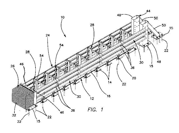
Fig. 1 is an isometric view of an exemplary embodiment of a crash
attenuator constructed in accordance with the principles of the present
invention,
disposed in a deployed orientation;
Fig. 2 is a top plan view of the crash attenuator of Fig. 1;
11
CA 03182100 2022-11-01
WO 2021/257410
PCT/US2021/037116
Fig. 3 is an elevation view of the crash attenuator of Fig. 1;
Fig. 4 is a detail view of the portion 4 of Fig. 3;
Figs. 4A-4G are various views of a bent washer plate and bolt assembly
shown in Fig. 4;
Fig. 5 is a cross-sectional view along lines 5-5 of Fig. 3;
Fig. 6 is a cross-sectional view along lines 6-6 of Fig. 3;
Fig. 7 is a cross-sectional view along lines 7-7 of Fig. 3;
Fig. 8 is a cross-sectional view along lines 8-8 of Fig. 3;
Fig. 9 is an elevational view of an exemplary embodiment of the impact
head assembly of the invention;
Fig. 10 is a top plan view of the impact head assembly of Fig. 9;
Fig. 11 is a profile view of the impact head assembly of Figs. 9 and 10;
Fig. 12 is an elevational view of an exemplary embodiment of the
intermediate diaphragm assembly of the invention;
Fig. 13 is a top plan view of the intermediate diaphragm assembly shown in
Fig. 12;
Fig. 14 is a profile view of the intermediate diaphragm assembly shown in
12
CA 03182100 2022-11-01
WO 2021/257410
PCT/US2021/037116
Figs. 12 and 13;
Fig. 15 is an elevational view of an exemplary embodiment of the backup
structure assembly of the invention;
Fig. 16 is a top plan view of the backup structure assembly shown in Fig.
15;
Fig. 17 is a profile view of the backup structure assembly shown in Figs. 15
and 16;
Fig. 18 is a top plan view of an exemplary embodiment of the track
assembly of the invention;
Fig. 18A is a top plan view of the inset area 18A shown in Fig. 18;
Fig. 18B is an elevational view of the inset area 18B shown in Fig. 19;
Fig. 19 is an elevational view of the track assembly of Fig. 18;
Fig. 20 is a top plan view, similar to Fig. 18, of an exemplary embodiment
of the track assembly of the invention;
Fig. 21 is an elevational view of the track assembly of Fig. 20;
Fig. 22 is a cross-sectional view along lines 22-22 of Fig. 21;
Fig. 23 is a cross-sectional view along lines 23-23 of Fig. 21;
13
CA 03182100 2022-11-01
WO 2021/257410
PCT/US2021/037116
Fig. 24 is an elevational view of an exemplary embodiment of the first stage
rail assembly of the present invention;
Fig. 25 is a cross-sectional view taken along lines 25-25 of Fig. 24;
Fig. 26 is an elevational view of an exemplary embodiment of the second
stage rail assembly of the present invention;
Fig. 27 is a profile view of the second stage rail assembly shown in Fig. 26;
Fig. 28 is an elevational view of the portion of Fig. 26 denoted by the
numeral 28;
Fig. 29 is an elevational view of an exemplary embodiment of the third
stage rail assembly of the present invention;
Fig. 30 is a profile view of the third stage rail assembly shown in Fig. 29;
Fig. 31 is an elevational view of the portion of Fig. 29 denoted by the
numeral 31;
Fig. 32 is an elevational view of an exemplary embodiment of the fourth
and fifth stage rail assemblies of the present invention;
Fig. 33 is a profile view of the fourth and fifth stage rail assembly shown in
Fig. 32;
Fig. 34 is an elevational view of the portion of Fig. 32 denoted by the
numeral 34; and
14
CA 03182100 2022-11-01
WO 2021/257410
PCT/US2021/037116
Fig. 35 is an elevational view of the portion of Fig. 32 denoted by the
numeral 35.
Detailed Description of the Invention
Referring now more particularly to the drawings, Figs. 1-3 illustrate an
exemplary embodiment of a fixed crash impact attenuator or crash cushion
system
of the type discussed above, wherein the design is sacrificial, in that after
an
10 impact, it is repaired or replaced. Thus, it is designed to be
relatively inexpensive
and simple in design and construction, yet highly effective in protecting the
occupants of vehicles striking the attenuator, either directly or obliquely.
The energy dissipation mechanism of the present invention is a tearing
member which is forced through a base material, such that energy dissipation
is
achieved through fracture of the base material. The inventive system is
innovative
in part because of its ability to control and vary the force level and energy
dissipation of the fracture of the base material through several parameters,
including the use of different types of tearing members, alteration of the
base
material's cross section through various forms of holes, incisions, and stress
concentrators, and variation of the base material itself Modification of these
aspects of the energy dissipation mechanism allows for variation in force
levels and
energy dissipation developed by the material fracture through alteration of
the
fracture mode, the number of fracture surfaces, and the length of the material
fracture. In its simplest form, the energy dissipation may consist of the
tearing
member being forced through a constant cross-section of base material to form
a
single fracture line. Alternatively, the introduction of various
modifications, such
as those listed herein, could produce multiple fracture modes along multiple
fracture lines for a more refined energy dissipation.
Design considerations for the system 10 are that it is designed and tested to
CA 03182100 2022-11-01
WO 2021/257410
PCT/US2021/037116
meet U.S. federal TL (Test Level) -3 crash attenuation specifications, that it
is
narrow in profile, bi-directionally capable, MASH (Manual for Assessing Safety
Hardware) compliant, inexpensive, and free-standing (does not need to butt to
rigid
object, though it is capable of such an attachment). The system is of a simple
design and easy to manufacture (materials are standard sizes and shapes and
side
panels are standard Thrie Beam-based, such as the AASHTO M-180 profile), easy
to assemble, and ships as a complete assembly. The base is the drill template,
and
anchor holes can be drilled with the unit 10 assembled. The length of the unit
as
designed, in an exemplary embodiment, is approximately 20-24 feet. Its width
is
32 inches or less, which permits the units 10 to be shipped three-wide on a
truck.
The height may range from 31 to 36 inches in exemplary embodiments. The unit
10 may be anchored to concrete, asphalt, or a hybrid of both, and it may be
anchored using standard anchors and adhesives. It is suitable for use in
temperatures ranging from below -40 degrees to 150+ degrees F.
The system 10 comprises a base portion or track assembly 12 having a
ladder frame design, as particularly shown in Fig. 2, comprising a plurality
of
intermediate base plates 14 supporting first and second outer rails 16 and 18,
respectively, with a larger terminal base plate 15 at each end. The
intermediate
base plates 14 and terminal base plates 15 each include anchor holes 20 for
anchoring the base to the ground using bolt anchors 22 or other suitable
mechanical
fasteners. In some instances, adhesive may be used instead or as well. The
anchor holes 20, in the illustrated embodiment, may be spaced along a length
of
each base plate 14, 15, both outside of and within the first and second outer
rails
16, 18.
The system 10 further includes an upper attenuator portion 24, which
comprises an impact head assembly 26, a plurality of intermediate diaphragms
28,
comprising an intermediate diaphragm assembly extending between the impact
head assembly and the backup structure assembly, and a plurality of side
panels 30.
The impact head assembly 26 may comprise an object marker on its front end,
16
CA 03182100 2022-11-01
WO 2021/257410
PCT/US2021/037116
which may comprise warning striping or the like, and includes a crushable nose
box or energy absorber 32 in an exemplary illustrated embodiment. In the
illustrated embodiment, the crushable box 32 is filled with a honeycomb
material,
which is particularly adapted to be crushed and compacted to attenuate
impacting
forces (the honeycomb is not shown, for the purpose of clarity, in Figs. 9-
11). Of
course, suitable attenuating material other than honeycomb may be utilized, if
desired. The impact head 26 supports loads applied by frontal, side, and
angled
nose impacts.
The intermediate diaphragms 28 are disposed in spaced relation behind the
impact head 26. They are made from standard shapes and sizes and have cross
braces or brace tubes sized for loads. Each cross brace is positioned for ease
of
assembly of the side panels 30. Each intermediate diaphragm 28 is slidably
mounted at their base ends or feet 34 on each side to the side rails 16, 18,
as
illustrated. The rails 16, 18 are T-shaped, and the feet 34 on the diaphragms
28 are
of a "T-slot" configuration, so that they completely envelop and wrap around
the
upper flange portion of the "T" on the T-shaped rails. This is best shown in
Figs. 7
and 8, for example. As can be seen from those illustrations, this unique
configuration permits lateral loads from oblique impacts to be distributed to
both
rails 16, 18, whereas prior art crash cushions, typically using "C-shaped"
rails, only
permit lateral loading on the proximate track rail.
The side panels 30 may be standard in construction, and in the case of a
crash cushion of the type illustrated, may comprise a corrugated beam, such as
a
standard Thrie beam or w-beam panel, preferably fabricated of 10 or 12-gauge
steel. Plates or tubes may be utilized as well. When a vehicular impact
occurs,
and the attenuator is compacted, the intermediate diaphragms move successively
toward the rear of the crash attenuator 10, by sliding along the rails 16, 18.
As this
sliding movement of the intermediate diaphragms 28 occurs, the side panels 30
move rearwardly with the intermediate diaphragms to which they are attached,
being advantageously designed to nest or double over one another in a sliding
17
CA 03182100 2022-11-01
WO 2021/257410
PCT/US2021/037116
pattern. This mechanism will be described in greater detail below.
The length of the side panels 30 may be determined by loads in side or
oblique impacts, and may be dependent, at least to some extent, on the spacing
of
the diaphragms. The panels are preferably designed to be common and
interchangeable where possible, though only with other panels designed for
similar
stages of the attenuator system, of course. As shown in Figs. 4-8, bolt and
bent
washer plate assemblies 36 secure each side panel 30 to respective
intermediate
diaphragms 28, as well as securing the adjacent side panel 30 to the impact
head
26, or a backup structure assembly 44. Each bolt assembly may comprise a
winged bent washer plate 38 secured by a bolt 40, having a bolt head 42. This
shaped washer plate configuration has an advantage of controlling the fracture
path
and panel motion in a more advantageous way. The steel forming the side panels
may be galvanized, and may be A36, A513, or A517, for example. Figs. 4A-4G
illustrate, respectively, an isometric view of the bolt and bent washer plate
assembly 36, showing the bent washer plate 38 having bent wings 38a and a
center
portion 38b. Employing flared front wings 38a on the washer plate 38, with
forward positioning of the bolt 40, shortens the distance to the shank face,
thereby
limiting buildup in front of the tearing member (bolt) 40 and under the
washer. The
shaped washer plates also function to assist in controlling the fracture path
and
panel motion during the tearing process. Fig. 4B is a profile view of the
assembly
of Fig. 4A, Fig. 4C is an elevation view, Fig. 4D shows a flat pattern of the
bent
washer plate 38, Fig. 4E is a flat pattern side view of the bent washer plate
as
shown in Fig. 4D, Fig. 4F is an elevation view of the bent washer plate 38,
and Fig.
4G is a profile view of the bent washer plate 38. The center portion 38b of
the
bent washer plate 38 includes a hole 39 for receiving the bolt 40.
As shown more particularly in Figs. 5 and 9-11, the impact head assembly
26 may comprise, in addition to the crushable box 32, upright struts 46,
having base
ends 47 which are similar to base ends or feet 34 of the intermediate
diaphragms
28, though longer, and adapted to slide along the rails 16 and 18.
18
CA 03182100 2022-11-01
WO 2021/257410
PCT/US2021/037116
Figs. 6 and 15-18B illustrate the backup structure assembly 44, which
comprises upright pillars 48 and angled support braces 50 (Figs. 1-3 and 15-
17).
The upright pillars 48 and angled support braces 50 comprise the terminal base
plates 15, which may be anchored in the ground using bolt anchors 22. It
should
be noted that the specific structural features of the backup structure
assembly 44
may vary in accordance with desired applications, and that, if desired, the
crash
attenuator 10 may be secured to the fixed structure which is being guarded,
using
end treatment hardware of known design.
Figs. 7-8 and 12-14 illustrate the intermediate diaphragms 28, comprising
the intermediate diaphragm assembly, in greater detail. The diaphragms 28
comprise upstanding struts 54, at the lower end of which are disposed the base
ends
or feet 34. The struts 54 are secured together by cross-members 56. As best
shown in Figs. 7 and 8,
Figs. 18-23 illustrate, in particular detail, an exemplary embodiment of the
track assembly 12, which comprises the first and second side rails 16, 18,
respectively, secured to the longitudinally spaced intermediate base plates
14. On
both ends of the crash attenuator 10, the rails 16, 18 extend lengthwise along
the
larger terminal base plates 15 anchored there for supporting each of the
impact
head on one end and the backup structure assembly on the second end.
As shown particularly in Fig. 2, an impacting vehicle, in a frontal crash,
may impact the nose piece or impact head 26 in a direction from left to right,
as
denoted by the arrow 58. The system can also attenuate crashes by vehicles
impacting from the side or at an angle. The upper attenuator portion is
divided
into a plurality of stages, for the purpose of tuning and controlling the
attenuation
properties of the crash cushion 10. In the illustrated exemplary embodiment,
the
upper attenuator portion 24 comprises a Stage 1 rail assembly 60, a Stage 2
rail
assembly 62, a Stage 3 rail assembly 64, a Stage 4 rail assembly 66, and a
Stage 5
rail assembly 68, each comprised of a uniquely designed panel, with a smooth
transition between panels/stages. The resultant inertia pulse elongation
reduces
19
CA 03182100 2022-11-01
WO 2021/257410
PCT/US2021/037116
force peaks, thus improving impacting vehicle occupant safety.
The present invention utilizes an energy absorption mechanism employed
in the crash attenuator system, which is the designed mode of tearing of
elements of
the attenuator system as the forces imposed by an impacting vehicle are
absorbed.
In the illustrated embodiments, the energy absorption method is to tear the
side or
fenderfende panels 30, using the panel connection hardware, comprised of bolt
assemblies 36, as the tearing hardware. Of course, it is within the scope of
the
invention to utilize other system components as the objects to be torn, and
other
tearing members, such as an independent washer plate/assembly or other
penetrating elements, such as rods, plates, wedges, and the like, as the
tearing
hardware. The form of the tearing member can be used to dictate the fracture
mode and the number of fracture surfaces developed within the base material,
as
well as control the propagation of the fracture path through the base
material.
Multiple tearing members may be used in a section of base material to produce
additional fracture surfaces and increase force levels and energy dissipation.
Particularly innovative is that the system is designed to be tuned to tear and
shear in a controlled manner, in order to maximize impact force attenuation
ability
and to minimize injury to vehicle occupants to the extent possible, permitting
ride-
down forces experienced by the vehicle occupants to be substantially below
permitted levels under federal crash standards. The means for tuning the
tearing
levels include, but are not necessarily limited to, adjusting component
thicknesses
to vary along each stage of the attenuator, utilizing cut-outs in the
components to be
torn to manage the tearing process, ranging from a component formed of solid
material, to a series of holes of various configurations and spacings, such as
slots,
triangles, including isosceles triangles and equilateral triangles,
trapezoids, semi-
circles/crescents, perforations, rectangles, and the like. The cut-out sizes
can be
varied, as well as the spacings between holes, as noted above. A plurality of
rows
of holes may be employed in each component, wherein the holes are either
aligned
or staggered with respect to holes in adjacent rows. An objective of this
tuning
CA 03182100 2022-11-01
WO 2021/257410
PCT/US2021/037116
can be to initiate one, two, or three different types of tearing modes,
depending
upon shape/pattern of the holes and their spacing, as well as component
thickness,
including Mode 1 (tensile failure), Mode 2 (shear failure), Mode III (out-of-
plane
shear), and combinations of modes. Control of tearing is designed to result in
a
consistent and predictable path, created through the planned usage of
perforations,
pattern spacing, grooves or scoring, and the design of the tearing modality,
which
in the exemplary embodiment involves an innovative washer plate design used
with
the bolt assemblies 36, wherein the winged washer 38 has a limited front
extension
to allow curling of the fender panel and to prevent buildup. Various materials
can
be used for the components to be torn (e.g. the fender panels 30 in the
exemplary
embodiment), such as various steels, aluminums, plastics, and FRP (Fiber-
Reinforced Plastic). Pattern staggering, as noted above, may be employed to
limit
force peaks, and tearing can occur through the valley or peak of rails, or
anywhere
on the panel.
It should be noted, at this juncture, that the terms "tear", "tearing",
"tearable", and the like are used herein and in the appended claims as stand-
ins for
any of the above mentioned terms for creating a lengthwise fracture or slit in
a
crash attenuator component to attenuate impact energy, and are intended to be
broad enough in scope to include any of these terms.
With the foregoing in mind, Figs. 24-25 illustrate an exemplary first stage
(Stage 1) of the crash attenuator 10, which is comprised of first fender
panels 30,
disposed in opposed fashion along both sides of the attenuator system 10, as
shown
particularly in Figs. 2 and 3, extending rearwardly from the impact head 26.
As
illustrated, the panels 30 in Stage 1 include two rows 74, 76 of
longitudinally
arranged and spaced holes 78, which in this case are shaped as triangles, or
more
particularly isosceles triangles in particular embodiments. Each row 74, 76
lies in
alignment with respective bolt holes 70 for receiving the bolts 40 of the
panel bolt
assemblies 36. Location 72 accommodates a gusset that is welded to the back of
the Thrie beam fender panel 30. This gusset reinforces the panel where the
21
CA 03182100 2022-11-01
WO 2021/257410
PCT/US2021/037116
shearing bolt 40 goes through, thereby forcing the downstream bolt to extrude
through the panel. The winged washers 38 are welded to respective shearing
bolts
40. As shown in Fig. 24, an elongated slot 80, which may also be round, oval,
or
another shape, is disposed at the rear end of each row 74, 76. The purpose of
the
slot 80 is to receive the bolt 40 of the bolt assembly securing the front end
of the
next overlapping panel 30 to the second intermediate diaphragm 28, in the
initial
deployment state of the crash attenuator 10. The use of slots, teardrops, and
other
special shapes facilitates stress concentrations at the start of a panel to
thereby
facilitate initiation of fracture. The first panel is attached to the impact
head 26 at
the front, spans a first intermediate diaphragm 28, the is bolted to the
second
intermediate diaphragm 28. On impact by a vehicle exerting impact force in the
direction of arrow 58 (Fig. 2), the first panels 30 get accelerated from left
to right in
the drawing, riding along with the impact head 26 to which they are attached
at
their respective front ends, so the oval slot 80 is where the tearing bolt 40
will start
the tearing process, the bolt moving forwardly relative to the panel until the
bolt 40
reaches the front end of the panel 30 on the leftmost end of its respective
row 74,
76. Because
the tearing action initiated by the bolt 40 in the material of the panel
30 creates a fracture or slit expanding forwardly along the panel, even though
the
panel is moving rearwardly responsive to the vehicular impact force 58, the
rearmost end of the panel is softer than or uniform with the front most end of
the
panel, as noted above.
Because Stage 1 is the first stage to receive and attenuate the impact force,
it is designed to be the softest, with each successive stage being designed to
be
stiffer than the one before. In stage 1, as noted above, the holes 78 may be
triangular, and more particularly isosceles triangles in particular
embodiments.
Triangular shapes are particularly suited for a single Mode 1 fracture with no
debris. During an impact, the tearing bolt 40 moves through the panel 30 from
right to left opposite the direction of the panel, as noted above. As the
tearing bolt
40 moves into the triangular hole 78, the bolt hits the two diverging sides of
the
22
CA 03182100 2022-11-01
WO 2021/257410
PCT/US2021/037116
triangle, creating a tensile load at the left point of the triangle. As noted
above,
this starts a Mode 1 tensile failure in the material ahead of the tear bolt,
and
occasionally, Mode II shearing will also be present, particularly at the
beginning of
the tearing process.
As noted above, Stage 2, illustrated in Figs. 26-28, is the next stage, and
next fender panel 30 to be impacted. It is designed to be stiffer than Stage
1, but
still relatively soft, since impact forces are still quite high, after
attenuation only by
the impact head and the Stage 1 panels. In Stage 2, the panel 30 has two rows
74,
76, along the same location as in Stage 1, of holes 82. These holes 82 are
also
illustrated as triangular, but of a smaller nature than the holes of Stage 1,
and more
closely spaced. The triangles may be isosceles triangles, or, as illustrated,
equilateral triangles, but may also be of alternate shapes, such as round,
trapezoidal,
rectangular, and the like. In the illustrated embodiment, there are thirty-
three holes
82 along a 32-inch length of each of the rows 74, 76. Of course, this is
merely an
exemplary number, as the actual number of holes and spacing between them can
vary, depending upon design considerations. Larger elongated holes 84 are
disposed on the downstream (right-most) end of each row 74, 76, for
accommodating the bolt 40 securing the panel 30 to the corresponding
intermediate
diaphragm 28. As the impact force continues, the panel 30 moves rightwardly,
causing the tearing bolts 40 to move (in a relative sense) leftwardly
(frontally)
along their respective rows 74, 76.
The next panel 30 comprises Stage 3, as shown in Figs. 29-31. This stage
appears similar to stage 2, in that the shape of the holes is the same, but in
this
exemplary embodiment, there are twenty-nine holes 85 along a 311/2 inch length
of
each of the rows 74, 76. Thus, the stage 3 panel 30 is "stiffer" than the
stage 2
panel 30, because of the fewer, more widely spaced holes 85 compared to the
holes
82 of the Stage 2 panel.
Stages 4 and 5 are illustrated in Figs. 32-35, wherein the fourth and fifth
stage fender panels 30 also have two rows of holes 74, 76. In the illustrated
23
CA 03182100 2022-11-01
WO 2021/257410
PCT/US2021/037116
embodiment, the same panels 30 are used for both Stages 4 and 5, and the panel
utilizes trapezoidal holes 86. Circular holes 90 function to initiate the
tearing in
this stage. It should be noted that in Stages 4 and 5, the relative axial
locations of
the trapezoidal holes 86 in each row 74 and 76 are staggered, rather than
being
aligned. The purpose of this staggering is to create a more even force
attenuation,
smoothing the peaks and valleys of the force deflection curve. Trapezoids are
well
suited for dual Mode II/Mode III fracture.
If desired, later stage panels 30 may be comprised of a thicker material than
earlier stages, in order to further stiffen the later stages relative to the
earlier ones.
As noted above, the illustrated embodiment is exemplary only, and different
numbers of rows of holes, differing shapes of holes, different spacings,
staggerings
and the like, may be employed to create desired attenuation characteristics.
One
alternative exemplary embodiment, for example, utilizes isosceles triangles in
Stage 1, equilateral triangles in Stages 2 and 3, of various sizes and
spacings, and
trapezoids in Stages 4 and 5, also of various sizes and spacings. Rectangles,
with
or without perforations, may be utilized for dual Mode II/Mode III fracture.
It
should also be noted that, while the exemplary embodiment primarily comprises
stages which correlate to panel transitions, it is well within the scope of
the
invention to divide a single panel into a plurality of stages, by changing
material
thickness, holes sizes, hole spacing or other characteristics as described
herein
within the confines of a single panel rather than after transition from one
panel to
the next panel.
Advantageously, the invention contemplates utilizing multiple fracture
surfaces in a single panel, longitudinal staggering of fracture modification
patterns,
and alternative spacing of shaped holes within a panel segment. It is
particularly
noted that the modification (holes) patterns on each of the panels, as
illustrated,
terminate early, before the end of the panel and the plate 72 and prior to
full-stroke,
in order to increase forces to bottom out the current panel and smoothly
transition
to an initiation of fracture in the subsequent panel while reducing inertial
forces.
24
CA 03182100 2022-11-01
WO 2021/257410
PCT/US2021/037116
Accordingly, although an exemplary embodiment of the invention has been
shown and described, it is to be understood that all the terms used herein are
descriptive rather than limiting, and that many changes, modifications, and
substitutions may be made by one having ordinary skill in the art without
departing
from the spirit and scope of the invention.