Note: Descriptions are shown in the official language in which they were submitted.
- 1 -
Description
Conveyor belt scraper system with simple maintenance
The invention relates to a scraper system for a conveyor belt, to a belt
conveyor
herewith and to a method for performing mounting, testing or maintenance work
on a
scraper system.
The use of scraper systems is known for conveyor belts of belt conveyors which
are
deployed for conveying most diverse conveyed goods. Known scraper systems
mostly
have a system carrier aligned transversely to the running direction of the
conveyor belt,
on which system carrier a plurality of scraper modules with scraper elements
are
located. By placing the scraper elements against the running conveyor belt,
any
conveyed goods adhering thereto can be scraped off.
Various types and designs of scraper systems and scraper modules are known.
For
example, DE 10 2017 114 931 Al shows a scraper system for arrangement in the
deflection region of a tripper pulley of a fast-running belt conveyor.
Scraping blocks
made of elastic material are fastened next to one another in an exchangeable
manner to
a spring-mounted system carrier which is arranged transversely to the running
direction of the belt conveyor.
DE 20 2020 104 666 Ui discloses a conveyor belt scraper, in particular a drum
scraper
having a number of scraping elements arranged next to one another on a cross
member. Each scraping element has an elastic base body and a holding device
for
fastening the scraping element to the cross member. The holding device has two
clamping parts which interlock in a clamping manner, one of which is fastened
to a
holding element which can be fixed on the cross member and the other is
fastened to
the base body.
CA 03182650 2022- 12- 13
- 2 -
DE 10 2013 006 821 Al describes a belt scraper system consisting of modules
for the
return region of conveyors. A system carrier is arranged transversely to the
running
direction of the conveyor belt. Multiple scraping modules are attached next to
one
another on the system carrier. The scraping modules each carry a scraping
lamella
which lies in contact with the belt in a peeling manner.
During the operation of the scraper system, the scraper elements, for example
scraping
lamellae or scraping blocks, are subject to considerable wear and have to be
regularly
replaced.
US 4,098,394 describes a mounting and support arrangement for conveyor belt
scrapers. Multiple cleaning blades are fastened to arms on a cross-shaft. A
radial
ratchet and pawl arrangement for rotation of the cross-shaft is provided
exterior to a
housing in order to bias the blades against the conveyor belt. If the blades
are to be
repaired or replaced, the cross-shaft is removed by removing a coupling at one
end and
by removing a sleeve at the opposite end. A mounting flange is disassembled
from a
side wall and the cross-shaft with the scraper assembly is removed from the
housing 28
through an access door.
In the case of known scraper systems, access to scraper modules required for
maintenance can be difficult, in particular if dangerous regions beneath the
conveyor
belt have to be entered. It can therefore be regarded as an object to propose
a scraper
system, a belt conveyor herewith as well as a method for performing mounting,
testing
or maintenance work on a scraper system, which makes it possible for the
maintenance
personnel to access scraper modules in a simple manner, avoiding risks.
The object is achieved by a scraper system for a conveyor belt according to
Claim 1, a
belt conveyor according to Claim 12 and a method according to Claim 13.
Dependent
claims refer to advantageous embodiments of the invention.
The inventors started from the consideration that it is particularly complex
to carry out
work on the scraper system, in particular mounting, testing or maintenance
work
relating to the scraping modules, if dangerous areas of the plant have to be
entered and
therefore safeguard measures such as, for example, the installation of
scaffolding or
CA 03182650 2022- 12- 13
- 3 -
similar as well as longer operational interruptions are required. The
possibility of
performing maintenance work on scraper modules from outside the belt region
would
therefore be of particular interest. In order to achieve this, the inventers
propose a
scraper system, in which the system carrier having the scraper modules (or at
least
having one scraper module) can be pulled off laterally in the simplest
possible manner.
The scraper system according to the invention includes a system carrier and at
least one
scraper module attached thereto, preferably multiple scraper modules attached
to the
system carrier, in each case having a scraper element for abutting against the
conveyor
belt. The system carrier is provided for arrangement transversely to the
conveyor belt.
It is preferably configured as a shaft that can be rotated about a
longitudinal axis or can
be tensioned in the rotational direction. In principle, the system carrier can
have any
cross-sectional shape, but is preferably of a round cross-section at least in
certain
sections, particularly preferably at least in the region of the two opposite
end regions.
In a preferred, particularly simply designed embodiment, the system carrier is
configured as a continuous tube, preferably having an unchanged round cross-
section
throughout.
The scraper module or the scraper modules is/are preferably detachably
attached to the
system carrier, particularly preferably detachably fastened to the system
carrier in a
clamping holding device. The respective scraper element can be, e.g., a
scraping block
made of a flexible material, in particular if the scraper is arranged as a pre-
scraper, i.e.,
in the region of a deflection of the conveyor belt. The scraper element
preferably has a
scraping edge, particularly preferably made of metal, e.g., hard metal
(tungsten
carbide). This can more preferably lie in contact with the conveyor belt in a
peeling
manner, in particular in the return region.
A holding device for attachment to the belt conveyor is provided for the
system carrier.
According to the invention, the holding device includes at least one
attachment part for
stationary attachment relative to a belt scaffold of the conveyor belt, a
holding element
for attaching the system carrier to the attachment part and a supporting
element on the
attachment part. In an operational arrangement, i.e., an arrangement in which
the
scraper system fulfils its function during the operation of the conveyor belt,
the holding
device having the attachment part, holding element and supporting element is
CA 03182650 2022- 12- 13
- 4 -
preferably provided in the region of an end of the system carrier, more
preferably
laterally outside the width of the conveyor belt. A counter support, which can
preferably
have a simpler construction as explained in greater detail below, can be
provided on the
opposite side.
The attachment part can be part of the belt scaffold or can preferably be
fixedly
connected to the latter. In a preferred embodiment, the attachment part can be
plate-
shaped or can have at least one plate-shaped section for attachment of the
holding
element.
According to the invention, the holding element is coupled to the system
carrier via a
tensioning arrangement, by means of which the system carrier can be acted upon
with a
torque about its longitudinal axis. Due to the torque, the scraper elements
can
preferably be pressed onto the conveyor belt. The tensioning arrangement
preferably
acts between the holding element and the system carrier, e.g., via an element
attached
in a rotationally fixed manner to the system carrier, e.g., a tensioning arm.
The
tensioning arrangement can have, e.g., a tensioning element such as a pawl and
ratchet,
a tensioning screw and/or a spring element which has the effect of applying
the torque
between the holding element and the system carrier.
According to the invention, the holding element can be detachably connected to
the
attachment part. In the operative position, the holding element is connected
to the
attachment part and the system carrier is held on the attachment part via the
holding
element. By detaching the holding element from the attachment part, the
scraper
system can be transferred from the operative position into a assembly
arrangement, in
which the system carrier having the scraper module and the holding element can
be
extracted in its longitudinal direction into an extracted position. When the
system
carrier is extracted in its longitudinal direction, the scraper module can
pass the
attachment part (as well as preferably the supporting element). For this
purpose, a free
region of sufficient size and a suitable shape is preferably provided, such
that when the
system carrier moves solely in the longitudinal direction, i.e., preferably
without a
movement in the transverse direction, the scraper module or the scraper
modules as
well as the holding element can also pass the attachment part and preferably
the
supporting element. The free region can be formed at least in part by a cutout
on the
CA 03182650 2022- 12- 13
- 5 -
supporting element. During or prior to the extraction, starting from the
operative
position, in which the scraper element abuts against with the conveyor belt,
the system
carrier together with the scraper module attached thereon can possibly be
rotated to a
certain extent, so that projecting parts can pass the free region.
According to the invention, it is provided that, in the extracted position
(and preferably
continuously during the process of extracting the system carrier), the
supporting
element supports the system carrier. The supporting element can preferably be
provided on the attachment part in a fixed or detachable manner; it is also
possible that
the supporting element is configured integrally with the attachment part. The
supporting element can particularly preferably be hook-shaped and at least
partially
encompass the system carrier. Whilst the supporting element preferably does
not have
any contact with the system carrier in the operative position, it can take
over the
supporting of the system carrier immediately after detaching the connection
between
the holding element and the attachment part. Thus, the weight of the system
carrier
and of the scraper modules does not have to be supported in another way by
manual
holding or supporting on a scaffold to be specially attached or similar.
Extracting the system carrier in the longitudinal direction thereof is
preferably to be
understood to be a linear, translatory movement. During the transfer into the
extracted
position, the scraper module passes the attachment part, i.e., it is located
in the
operative position on a first, inner side of the attachment part and in the
extracted
position on the opposite, outer side thereof.
The scraper system according to the invention thus makes it possible to
extract the
system carrier laterally into the extracted position, in which the scraper
module is
located outside the attachment part and is easily accessible for mounting,
inspection or
maintenance purposes. The supporting element causes the system carrier to be
supported such that the latter does not have to be held by the operator and
the risk of it
falling down is reduced or eliminated. The supporting action of the supporting
element
is understood to be an effect of force directed vertically upwards, i.e., the
system carrier
can preferably rest on the supporting element.
It is preferred that the supporting element does not support the system
carrier until
CA 03182650 2022- 12- 13
- 6 -
after the holding element has been detached from the attachment part, i.e., in
the
operative position no direct contact exists between the supporting element and
the
system carrier, but a small distance remains of, e.g., at least 0.5 mm or 1
mm,
preferably less than 5 cm, particularly preferably less than 1 cm. After
detaching the
holding element from the attachment part, the side of the system carrier
connected to
the holding element can preferably be lowered by this small amount until it
comes into
contact with the supporting element. The arrangement is preferably such that
as long
as the system carrier remains in an opposite counter-support device, only a
small tilting
of the system carrier of, e.g., less than 50, particularly preferably less
than 10 is
produced.
Thus, it is possible to carry out simple maintenance on and, in particular, to
simply
exchange scraper modules or scraper elements on the scraper system according
to the
invention, without necessarily having to enter the region beneath the conveyor
belt. By
supporting the system carrier during extraction or in the extracted position,
the
handling is particularly simplified and the operation can preferably be
performed by a
single person.
For the attachment of the holding element to the attachment part, various
types of
connection can be used, wherein a detachability which is as simple as possible
is
preferred, but sufficient stability is required in operation. For example, a
screw
connection with one or more screws can be provided.
According to a further development of the invention, the holding element is
connected
to the attachment part by means of a screw connection in combination with at
least one
plug connection, preferably two plug connections which are arranged at a
distance from
one another. The plug connection or the plug connections are preferably
designed such
that that they are aligned in the direction of the longitudinal axis of the
system carrier,
such that the holding element can be removed from the attachment part
following the
releasing of the screw connection in the longitudinal direction of the system
carrier. A
bolt is preferably used as the plug connection, which bolt is received in a
receiving
opening. The bolt is particularly preferably arranged on the attachment part
and the
receiving opening is arranged on the holding element, although the reverse
arrangement is also possible. The screw connection as well as the plug
connection(s)
CA 03182650 2022- 12- 13
- 7 -
are preferably aligned parallel to one another. Only one screw is particularly
preferably
provided, which is arranged between two plug connections. Thus, a sufficiently
fixed
connection can be utilized for the operation, which can be very quickly and
simply
detached.
According to a further development, it is provided that the supporting element
partially
encompasses the system carrier. To this end, the inner shape of the supporting
element, which faces the system carrier, can correspond at least in certain
sections to
the contour of the system carrier. For example, with a round contour of the
system
carrier, the inner shape of the supporting element can be partially circular.
The
supporting element can preferably have a recess, in which the system carrier
is in part
received and thus supported and secured against movements in the transverse
direction, in particular against dropping out. The supporting element more
preferably
encompasses the system carrier over a first part of the circumference thereof,
while it
leaves free a second part of the circumference of the system carrier such
that, when the
system carrier is extracted, the scraper module can pass the supporting
element. The
first circumferential part over which the system carrier is encompassed by the
supporting element can, e.g., be at least 90 and up to 180 , with
encompassing over a
circumferential region >115 and <155 being preferred. Thus, good support is
ensured,
such that a risk of the system carrier dropping out is minimized. On the other
hand, too
wide and in particular complete encompassing is not preferred, such that the
system
carrier having the scraper module can still be extracted. The shape of the
supporting
element is preferably adapted at least over the first circumferential part of
the outer
contour of the system carrier; the system carrier particularly preferably has
a round
cross-section at least in certain sections and the supporting element is
partially
annular.
In a preferred embodiment, the attachment part is arranged vertically above
the system
carrier and the supporting element extends vertically downwards in the
direction of the
system carrier, such that it at least partially encompasses the latter. At
least one section of
the supporting element preferably encompasses the system carrier to such an
extent that
the latter is arranged between the attachment part and the encompassing
section of the
supporting element, i.e., the encompassing section of the supporting element
extends
preferably to below the system carrier.
CA 03182650 2022- 12- 13
- 8 -
A rotary bearing is preferably provided between the holding element and the
system
carrier, which allows at least a slight rotation relative to one another in
order to thus
preferably modify the arrangement and in particular the bias between the
scraper element
and the conveyor belt. The rotary bearing can be formed in various ways,
preferably as a
bearing bushing, particularly preferably as a plastic bushing.
In a preferred embodiment, the holding element is designed at least in
partially plate-
shaped and the system carrier penetrates the holding element, preferably
perpendicularly
thereto. Such an arrangement is particularly simple in construction and
enables a stable
fastening, in particular if the attachment part and/or the supporting element
also are
plate-shaped and are arranged on one another.
As already mentioned, a counter support to the holding device is preferably
provided such
that the system carrier is mounted in the holding device and the counter
support. Like the
(first) attachment part of the holding device, a second attachment part is
preferably
provided for the counter support, which is arranged at a distance from the
first attachment
part in the longitudinal direction of the system carrier. The system carrier
is preferably
rotatably mounted on the second attachment part and displaceably mounted in
its
longitudinal direction. To this end, a bearing sleeve for the system carrier
can also be
preferably provided on the second attachment part or on an element connected
therewith,
particularly preferably as a bearing bush, e.g., made of plastic. The counter-
bearing is
preferably not locked in the longitudinal direction of the system carrier such
that the
system carrier can be extracted from the counter support, after detaching the
support
device, without further measures. Thus, a disassembly with access only from
the side of the
holding device is possible, without access to the counter support being
required.
According to a preferred embodiment, an extraction aid can be provided for the
system
carrier, which can be attached to the system carrier such that it extends in
the extension
thereof in the longitudinal direction of the system carrier. Such an
extraction aid can help
to grab and to guide or hold the system carrier during extracting. The
extraction aid and/or
system carrier preferably has/have an insertion opening at the end such that
the extraction
aid and the system carrier can be inserted into one another. An interposed
piece, i.e., an
adapter, for coupling the extraction aid and the system carrier can also be
used. Such an
CA 03182650 2022- 12- 13
- 9 -
adapter can have, e.g., a clamping device for clamping with the system carrier
and an
engagement section for coupling to the extraction aid. More preferably, a
locking device for
fixing the extraction aid to the system carrier and/or to the adapter can be
provided such
that an unintentional removal can be avoided.
As already explained, various types of scraper modules can be attached to the
system
carrier. According to a preferred embodiment, the scraper module (or
preferably all of the
scraper modules) has/have a module arm to which the scraper element is
attached. The
module arm can be pivoted in a module joint, preferably about an axis which is
aligned at
least substantially parallel to the longitudinal direction of the system
carrier. This is to be
understood to mean that the alignment can also include a slight oblique
position or slight
rotation, preferably at angles <30 , more preferably <20 , particularly
preferably <100.
The scraper module preferably has a spring element in order to act on the
module arm
with a torque. Different types of spring elements are possible, with a rubber
torsion spring
being preferred. The spring element can cause the scraper element to press
against the
conveyor belt. More preferably, the scraper module can have a stop for the
rotation of the
module arm in the module joint in order to restrict the pivot movement of the
scraper
element in the direction of the conveyor belt. If a spring element is used,
the stop is
preferably arranged such that the spring acts on the module arm in the
direction of the
stop, wherein there is still a bias at the stop.
A belt conveyor can be equipped with the scraper system according to the
invention such
that the scraper element abuts against the conveyor belt and the attachment
part is
fastened to the belt scaffold.
Work, e.g., mounting, testing or maintenance work, can be carried out on the
scraper
system according to the invention in a particularly simple manner in that,
starting from the
operative position, the holding element is detached from the attachment part,
the system
carrier having the scraper module and the holding element is extracted in the
longitudinal
direction of the system carrier, wherein, during the extraction of the system
carrier, the
supporting element supports the latter.
Embodiments of the invention are described in greater detail below, with
reference to
CA 03182650 2022- 12- 13
- 10 -
drawings, wherein:
Figs. 1, 2 show perspective views of a part of a belt conveyor having a
conveyor belt and
a scraper according to a first embodiment;
Fig. la shows an enlarged perspective view of a holding device from Fig. 1;
Fig. 3 shows a side view of the scraper from Figs. 1, 2;
Figs. 4, 5 show a scraper module of the scraper from Figs. 1-3 in a top view
as well as in
a partially cut-away side view;
Fig. 6 shows a cross-section through the scraper module from
Fig. 5 along the
line A..A;
Fig. 7 shows a perspective view of the scraper module from
Figs. 4, 5 having a
detached scraper element;
Figs. 8a-8e show perspective views of various positions of parts of the
scraper according
to the first embodiment during the extraction of the system carrier; and
Figs. 9a-9c show perspective views of the scraper according to the first
embodiment when
using an extraction aid;
Fig. 10 shows a cross-sectional view along line B..B from
Fig. 8b;
Fig. 11 shows a perspective view of a part of a belt conveyor
having a conveyor belt
and a scraper according to a second embodiment;
Fig. 12 shows a top view of a system carrier of the scraper from Fig. 11;
Fig. 13 shows a side view of the scraper from Figs. 11, 12;
Fig. 14 shows a view similar to Fig. 10 for the scraper from
Figs. 11¨ 13 according to
the second embodiment.
Figs. 1 and 2 show perspective views, for a first embodiment, of a part of a
belt conveyor 10
having a conveyor belt 12 which is deflected around a deflection drum 14. A
shaft of the
deflection drum is mounted on a belt scaffold 16, only parts of which are
depicted
schematically here.
On the belt conveyor 10, a scraper 18 having a plurality of scraper modules 26
is provided
with a system carrier 24 and a holding device 20 and counter support 22 for
attachment to
the belt scaffold 16.
The holding device 20 and the counter support 22 each have an attachment part
which is
CA 03182650 2022- 12- 13
- 11 -
fastened to the belt scaffold 16 or is part of the belt scaffold 16, here in
each case in the
form of attachment plates 28. A holding element in the form of a holding plate
30 is in
each case attached to the attachment plates 28.
In the embodiment shown, the system carrier 24 is a tube of a constantly round
cross-
section. The holding plates 30 each have round recesses with plastic sliding
bushes 33
inserted therein, in which the system carrier 24 is rotatably mounted.
In Fig. 3, two scraper modules 26 are depicted in a side view. The scraper
modules 26 each
include a base element 32 which is detachably attached to the system carrier
24 in a
clamping holding device 34. A scraper arm 36 is pivotably attached to the base
element 32
about a pivot axis 38. A scraping element holder 40 having a scraping element
42 is in each
case arranged at the end of the scraper arm 36.
As can be seen, e.g., from Fig. 2, multiple scraper modules 26 are arranged
next to one
another on the system carrier 24. The system carrier 24 extends in the
direction of the
width of the conveyor belt 12, that is to say transversely to the running
direction thereof. In
the case of the first embodiment, scraper modules 26 arranged next to one
another each
have in alternation shorter and longer scraper arms 36 such that the scraper
elements 42
are arranged in two staggered rows, wherein viewed in the running direction of
the
conveyor belt, a slight overlapping between the scraper elements 42 of the two
rows is
provided constantly. The scraper modules 26 are positioned next to one another
such that
the rows extend at least substantially over the entire width of the conveyor
belt 12.
During the operation of the belt conveyor 10 and of the scraper 18, scraping
edges of the
scraper elements 42 lie in contact with the surface of the conveyor belt 12 in
a peeling
manner, as shown in Fig. 3, in the example shown in the return region of the
conveyor belt
12. The scraper elements 42 are pressed in an elastic manner against the
surface of the
conveyor belt 12. Contaminants and adherent conveyed goods are thus scraped
off from
the running conveyor belt 12 by the scraper elements 42.
In Figs. 4,5, one of the scraper modules 26 is depicted in greater detail. As
shown there, a
joint 44 is provided between the base element 32 and the scraper arm 36 such
that the
scraper arm 36 can be pivoted about a pivot axis 38. As depicted, the joint 44
includes a
CA 03182650 2022- 12- 13
- 12 -
stirrup 46 encompassing the base element 32.
A rubber torsion spring (not depicted), which exerts a torque on the scraper
arm 36, acts in
the interior of the joint 44.
A protruding tab is provided as a stop 48 on the base element 32. In a stop
position, a part
of the stirrup 46 abuts against with the stop 48 such that the scraper arm 36
cannot pivot
further about the pivot axis 38. The rubber torsion spring is configured such
that it acts
upon the scraper arm 36 in the direction of the stop, wherein a bias 48 of the
spring
prevails in the stop position depicted in Fig. 5.
Due to the effect of the respective springs of the scraper modules 26, the
scraper elements
42 are pressed against the surface of the conveyor belt 12, but can take
evasive action by
pivoting in the joints 44 during the influence of corresponding forces during
operation,
e.g., due to stationary belt damage, elevations or similar on the surface of
the conveyor belt
12 by a corresponding pivot movement of the scraper arm 36 about the pivot
axis 38
against the effect of the spring.
A bias of the entire scraper 18, with which the entirety of the scraper
elements 42 is
pressed against the conveyor belt 12, is predefined by specifying a rotational
position of the
system carrier 24. A tensioning device 50 is provided on the holding device 20
therefor
between the holding plate 30 and the system carrier 24.
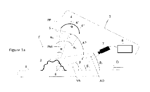
Fig. la shows the holding device 20 in an enlarged representation. A clamping
ring
attached to the system carrier 24 has a tensioning arm 54 protruding radially
from the
system carrier 24, which can be tensioned by means of a tensioning screw 56
with respect
to an attachment fixedly attached to the holding plate 30. By adjusting the
tensioning
screw 56, the system carrier 24 can thus be rotated and a bias of the springs
of the scraper
modules 26 can be set.
As is further shown in Figs. 1, la, a plate-shaped supporting element 80,
which is arranged
in the embodiment shown between the attachment plate 28 and the holding plate
30, is in
addition attached to the attachment plate 28 of the holding device 20. The
shape and
function of the supporting element 80 are explained in greater detail below,
with respect to
CA 03182650 2022- 12- 13
- 13 -
Figs. 8a-8d and Fig. 10.
During the operation of the scraper 18, constant wear to the scraper elements
42 results
such that regular inspection and maintenance are required. The scraper 18 is
designed in
terms of its attachment to the belt scaffold 16 as well as in terms of the
attachment of the
scraper elements 42 to the scraper modules 26 to be maintained in a
particularly simple
manner.
As is evident in particular from Figs. 4,5 and 7, the scraper arm 36 includes
two elements
which are detachably fastened to one another, namely a shaft 58 attached to
the scraper
element holder 40 and a sleeve 60 connected to the base element 32, namely
fastened to
the stirrup 46 of the joint 44. The shaft 58 is inserted into the sleeve 60
(Fig. 5) and is
secured by means of a twist lock 62 in the direction of a longitudinal axis 64
of the scraper
arm 36.
The longitudinal axis 64 extends in the embodiment shown, as is obvious from
Figs. 2 and
3, in a vertical view parallel to the running direction of the conveyor belt
12 and thus also
perpendicular, i.e., at an angle 13 of 90 (see Fig. 8e), to the longitudinal
axis of the system
carrier 24. In a horizontal view from the side (Fig. 3), the longitudinal axis
64 extends at an
angle y of approx. 9 to the running direction of the conveyor belt 12. The
longitudinal axis
64 in the embodiment shown is further aligned perpendicular, i.e., at an angle
6 of 90 , to
the contact edge of the scraping element 42 (see Fig. 4).
The shaft 58 can be freely rotated inside the sleeve 60 about the longitudinal
axis 64,
which is why the longitudinal axis 64 is also referred to as the rotational
axis. However, a
sealing ring 66 is provided which, on the one hand, causes a sealing of the
inner space of
the sleeve 60 with respect to the shaft 58 and, on the other hand, due to
friction because of
the contact with the inner side of the sleeve 60 produces a certain
sluggishness of the
movement of the shaft 58 with respect to the sleeve 60.
The twist lock 62 includes on the side of the sleeve 60 an elongated window
62a arranged
in the interior, which has a rim which protrudes into the interior of the
sleeve 60, and
includes on the side of the shaft 58 an elongated plate-shaped engagement
element 62b
which is fixedly attached at the end of the shaft 58 to an extension 63 having
a smaller
CA 03182650 2022- 12- 13
- 14 -
diameter.
As is obvious in particular from the cross-sectional view in Fig. 6, the
engagement element
62b and the window 62a are formed such that the engagement element 62b, when
aligned
parallel to the window 62a (dashed representation), can be inserted through
the latter in
the direction of the longitudinal axis 64, while it is locked in a twisted
position with respect
to the parallel alignment at the rim of the window 62a as shown (solid line).
Therefore, in terms of the fixing of the shaft 58 to the sleeve 60 in the
axial direction of the
longitudinal axis 64 there results a dependence on the rotational position:
In a position of the engagement element 62b parallel to the window 62a (dashed
representation), the shaft 58 having the scraper element holder 40 attached
thereto and
the scraper element 42 is located in a position within a release angular range
68a. In a
rotational position in the release angular range, the twist lock 62 is
released and the shaft
58 can be freely displaced in the longitudinal direction with respect to the
sleeve 60.
When the shaft 58 is further twisted with respect to the sleeve 60, the ends
of the
engagement element 62b engage behind the rim of the window 62a such that the
shaft 58
is fixed in the longitudinal direction with respect to the sleeve 60. The
corresponding
rotational positions of the shaft 58 are within a fixed angular range 68b, in
which the twist
lock 62 is locked.
As depicted, the release angular range 68a is centered around the rotational
position
shown dashed in Fig. 6, in which the front edge of the scraper element 42
provided for
abutting against the conveyor belt 12 is located at 90 to the longitudinal
direction of the
system carrier 24 and to the pivot axis 38 of the scraper module 26. By
contrast, the fixed
angular range 68b is centered around a rotational position which is rotated by
90 against
this and shown in Fig. 6 with a solid line. In this rotational position, the
scraping edge of
the scraper element 42 is aligned parallel to the longitudinal direction of
the system carrier
24 and to the pivot axis 38 of the joint 44.
Due to the free rotatability of the shaft 58 inside the sleeve 60, the
respective scraper
element 42 can, during contact with the conveyor belt 12, align itself
according to the
CA 03182650 2022- 12- 13
- 15 -
contour thereof. In practice, this will not be constantly planar over the
entire belt width but
will curve, e.g., towards the edges. Due to the contact pressure, the scraper
element holders
40 always adjust themselves such that the scraper elements 42 follow the shape
of the
conveyor belt 12.
However, a rotational position which lies within the release angular range 68a
is not
achieved in any operative position. The twist lock 62 thus constantly remains
in the fixed
angular range during the contact of the scraper element 42 with the conveyor
belt 12 and
thus ensures the fastening to the base element 32 of the respective scraper
modules 26.
In order to enable work on the scraper 18 and the scraper modules 26, in
particular to
make it possible to exchange the unit comprising the scraper element 42,
scraper element
holder 40 and shaft 26, the system carrier 42 with the scraper modules 26
attached thereto
can be detached in a particularly simple way and extracted laterally, as
explained below
with regard to Figs. 8a to 8e.
Therefor, on the side of the holding device 20, a particular attachment of the
holding plate
30 to the attachment plate 28 is provided and, on the side of the counter
support 22, a
bearing of the system carrier 24 in the bearing bush 33 of the holding plate
30 is provided
such that the system carrier 24 is freely movable in its longitudinal
direction.
As depicted in Fig. la, the holding plate 30 is fixed to the attachment plate
28 of the
holding device 20 by two plug connections 70 and a screw connection 72. The
plug
connections 70 are formed by two bolts arranged in parallel at a distance from
one another
on the attachment plate 28, which are received precisely fit in bores of the
holding plate
30. The plug connections 70 can be detached by removing the holding plate 30
from the
attachment plate 28 in the longitudinal direction of the system carrier 24.
The screw connection 72 formed between the plug connections 70 includes a
screw aligned
parallel to the bolts, with which screw the holding plate 30 is screwed to the
attachment
plate 28.
In an operative position for operating the belt conveyor 10 and the scraper
18, the holding
plate 30 is fixed to the attachment plate 28 by means of the screw connection
72.
CA 03182650 2022- 12- 13
- 16 -
If operation is interrupted, parts of the scraper 18 to be maintained can be
extracted by
transferring the scraper 18 into a assembly arrangement. By loosening the
screw
connection 72, the holding plate 30 can be detached from the attachment plate
28 by
subsequently also detaching the plug connections 7oa, 70b by pulling in the
direction of
the longitudinal axis of the system carrier 24. A handle 74 is provided for
this.
Fig. 8a shows, starting from the operative position, first of all the
releasing of the screw
connection 72. The holding plate 30 is subsequently pulled off from the
attachment plate
28, together with the system carrier 24 in the longitudinal direction thereof,
wherein the
plug connections 7oa, 70b are detached.
As already mentioned, the holding device 20 between the attachment plate 28
and the
holding plate 30 includes the supporting element 80. The supporting element 80
has, as is
obvious from Fig. 8b, a hook-shaped holding section 82 extending in the
direction of the
system carrier 24 and partially encompassing the latter, which configures a
recess 86. The
holding section 82 and the recess 86 have, as shown, an (in this case round)
inner contour
in certain sections corresponding to the (in this case round) outer contour of
the system
carrier 24. The holding section 82 is arranged in the operative position,
i.e., if the holding
plate 30 is fastened to the attachment plate 28 such that it does not touch
the system
carrier 24, but remains at a certain distance of a few millimeters herefrom.
Above the
holding section 82, the supporting element 80 has a cutout 84 through which
the system
carrier 24 passes.
In the assembly arrangement, i.e., following the releasing of the screw
connection 72 and
of the plug connections 7oa, 70b (Fig. 8b), the system carrier 24 sinks
slightly and
thereafter rests on the holding section 82 of the supporting element 80 in the
recess 86.
After detaching the connection between the holding plate 30 and the attachment
plate 28,
the supporting element 80 thus takes over the holding of the system carrier
24. As
depicted, the supporting element 80 is fastened to the holding plate 28 and
thus to the belt
scaffold 16. As depicted in Fig. 10, the holding section 82 encompasses the
system carrier
24 over a circumferential region a of approx. 135 at the recess 86 and
supports the system
carrier 24 from below such that the latter does not drop.
CA 03182650 2022- 12- 13
- 17 -
In the further course, the system carrier 24 is now pulled out in the
direction of its
longitudinal axis together with the holding plate 30 and the tensioning device
50 (Fig. 8b).
In the process, the supporting element 82 supports the system carrier 24 such
that the
latter does not fall down. Due to the displaceability of the system carrier 24
in the bearing
bush 33 of the counter support 22, it is possible to pull it out particularly
easily.
The scraper modules 26 can pass the attachment plate 28 and the supporting
element 80,
because the hook-shaped form of the holding section 82 which only partially
encompasses
the system carrier 24 with the cutout 84 leaves sufficient space free such
that when the
system carrier 24 is pulled out, the scraper modules 26 can be transferred
into an extracted
position outside of the belt region (Fig. 8d). The scraper modules 26 can thus
be guided
through a free area in the plane of the supporting element 80 as well as the
attachment
plate 28, without striking. The cutout 84 of the supporting element 80 forms
part of the
free area.
In the extracted position, the scraper modules 26 are easily accessible and
can be inspected
as well as maintained. In particular, worn scraper elements 42 can be replaced
by
detaching the respective units made up of the scraper element 42, scraper
element holder
40 and shaft 58 of the respective scraper module as described above by
twisting them
about the rotational axis 64, by separating them by removing them in the
longitudinal
direction and by subsequently attaching new elements in the same way.
Therefore, the process of inspecting and maintaining the scraper 18 is made
particularly
easy. In the embodiment shown, it is possible to pull out the system carrier
24 together
with the scraper modules 26 laterally by simply loosening a single screw
(screw connection
72). Due to the support provided by means of the supporting element 80, this
can be
carried out by a single person.
If there is sufficient space available to the side of the conveyor belt 12,
the handling of the
system carrier 24 can be made even easier when it is pulled out by using an
extraction aid.
To this end, as shown in Fig. 9a, an adapter 76 can first be fitted laterally
onto the system
carrier 24 and clamped on or otherwise fixed thereto. A tube can subsequently
be attached
to the adapter 76, which tube serves as an extraction aid 78 and is attached
in extension of
the system carrier 24. By means of the extraction aid 78, the system carrier
24 can be
CA 03182650 2022- 12- 13
- 18 -
handled particularly well, in particular in connection with the support on the
holding
section 82 of the supporting element 80.
A scraper 118 according to a second embodiment is shown in Figs. 11¨ 14. The
scraper 118
according to the second embodiment corresponds, in numerous details, to the
scraper 18
according to the first embodiment such that only the differences are explained
in greater
detail below and reference is made in other respects to the aforementioned
description.
The same reference numerals denote elements that corresponds between the
embodiments.
Whereas, in the case of the scraper 18 according to the first embodiment as
described and
depicted the scraping elements 42 are arranged in two rows, the scraper 118
according to
the second embodiment includes a single-row arrangement of scraping elements
42 on
scraper modules 126 which are each of identical length and which are arranged
next to one
another on the system carrier 24.
As is particularly obvious from Fig. 12, the scraping edges of the scraper
elements 42 are
not aligned in the transverse direction of the conveyor belt 12, as in the
case of the first
embodiment, but obliquely thereto at an angle which, in the depicted example,
is approx.
15 . However, the scraper arms 36 extend with their longitudinal axis 64, as
in the case of
the first embodiment, in the longitudinal direction of the conveyor belt 12,
i.e., as in the
case of the first embodiment, at an angle of 13 of 90 .
The scraper elements 42 are attached obliquely at an angle 8 of approx. 75 to
the scraper
arms 36. Adjacent scraper modules 126 on the system carrier 24 are arranged so
closely
that ¨ viewed in the longitudinal direction of the conveyor belt 12- a slight
overlapping of
the scraper elements 42 arises and thus a scraping effect over the entire belt
width.
In other respects, the scraper 118 according to the second embodiment is
identical in terms
of construction and function to the scraper 18 according to the first
embodiment, i.e., in
common with the scraper 18, each scraper 118 includes the base element 32
which is
detachably attached to the system carrier 24 in the clamping holding device 34
as well as
the scraper arm 36 which is attached pivotably about a pivot axis 38 and at
each end of
which a scraping element holder 40 having a scraping element 42 is arranged.
The biased
CA 03182650 2022- 12- 13
- 19 -
torsion spring imparts a torque such that, during the operation of the scraper
118, the
scraping edges of the scraper elements 42 lie in contact with the surface 12
of the conveyor
belt 12 in a peeling manner and are resiliently pressed against the surface 12
thereof in
order to scrape off contaminants. If there are stationary obstacles on the
surface of the
conveyor belt 12, the scraping elements 42 can take evasive action due to a
pivot movement
of the scraper arm 36 about the pivot axis 38 against the effect of the
spring.
Fig. 13 shows, for the second embodiment, a horizontal view from the side,
from which the
angle y between the running direction of the conveyor belt 12 and the
longitudinal axis 64
can be seen. Depending on the arrangement and setting, the angle y can be,
e.g., between
o and 2o ; in the embodiment shown, the angle y is approx. 15 .
In the case of the second embodiment as well, the scraper arm 36 includes the
shaft 58
attached to the scraper element holder 40, which shaft is inserted into the
sleeve 60 and
can be rotated about the longitudinal axis 64 therein. It is ensured by means
of the twist
lock 62 that the shaft 58 can only be pulled out of the sleeve 60 or inserted
into the latter at
the corresponding alignment, i.e., rotation from the normal position defined
by the belt
contact 60.
CA 03182650 2022- 12- 13