Language selection

Search

Patent 3184133 Summary

Third-party information liability

Some of the information on this Web page has been provided by external sources. The Government of Canada is not responsible for the accuracy, reliability or currency of the information supplied by external sources. Users wishing to rely upon this information should consult directly with the source of the information. Content provided by external sources is not subject to official languages, privacy and accessibility requirements.

Claims and Abstract availability

Any discrepancies in the text and image of the Claims and Abstract are due to differing posting times. Text of the Claims and Abstract are posted:

  • At the time the application is open to public inspection;
  • At the time of issue of the patent (grant).
(12) Patent Application: (11) CA 3184133
(54) English Title: A HYDRAULIC CYLINDER MOUNTING ARRANGEMENT
(54) French Title: AGENCEMENT DE MONTAGE DE CYLINDRE HYDRAULIQUE
Status: Compliant
Bibliographic Data
(51) International Patent Classification (IPC):
  • B62D 12/00 (2006.01)
  • B62D 53/02 (2006.01)
(72) Inventors :
  • LIETONEN, JANI (Finland)
(73) Owners :
  • SANDVIK MINING AND CONSTRUCTION OY (Finland)
(71) Applicants :
  • SANDVIK MINING AND CONSTRUCTION OY (Finland)
(74) Agent: GOWLING WLG (CANADA) LLP
(74) Associate agent:
(45) Issued:
(86) PCT Filing Date: 2020-08-26
(87) Open to Public Inspection: 2022-03-03
Availability of licence: N/A
(25) Language of filing: English

Patent Cooperation Treaty (PCT): Yes
(86) PCT Filing Number: PCT/EP2020/073895
(87) International Publication Number: WO2022/042837
(85) National Entry: 2022-12-22

(30) Application Priority Data: None

Abstracts

English Abstract

A cylinder mounting arrangement including: a mining vehicle having a frame; and at least one hydraulic cylinder (1) mounted to the frame of the vehicle, the cylinder (1) having a cylinder pin (10) for the mounting. In the invention the frame has an opening through which the cylinder (1) can be inserted inside the frame and also removed, and that a mounting element (8) has been assembled to one end of the cylinder (1), the mounting element (8) including a front plate (8') being assembled against the outside of the frame covering the opening (5) at least partially and two ears (8") for the attachment to the cylinder pin (10), and that the front plate (8') is fixed to the frame by mounting bolts (6) or screws from the outside the frame. The invention also relates to a mining vehicle.


French Abstract

L'invention concerne un agencement de montage de cylindre comprenant : un véhicule minier ayant un cadre ; et au moins un cylindre hydraulique (1) monté sur le cadre du véhicule, le cylindre (1) ayant une broche de cylindre (10) pour le montage. Selon l'invention, le cadre comporte une ouverture à travers laquelle le cylindre (1) peut être inséré à l'intérieur du cadre et également retiré et un élément de montage (8) a été assemblé à une extrémité du cylindre (1), l'élément de montage (8) comprenant une plaque avant (8') étant assemblée contre l'extérieur du cadre recouvrant l'ouverture (5) au moins partiellement et deux oreilles (8") pour la fixation à la broche de cylindre (10) et la plaque avant (8') est fixée au cadre par des boulons de montage (6) ou des vis à partir de l'extérieur du cadre. L'invention concerne également un véhicule minier.

Claims

Note: Claims are shown in the official language in which they were submitted.

7
CLAIMS
1. A cylinder mounting arrangement including:
a mining vehicle having a frame; and at least one hy-
draulic cylinder (1) mounted to the frame of the vehi-
cle, the cylinder (1) having a cylinder pin (10) for
the mounting, characterized in that the frame has an
opening (5) through which the cylinder (1) can be in-
serted inside the frame and also removed, and that a
mounting element (8) has been assembled to one end of
the cylinder (1), the mounting element (8) including a
front plate (8') being assembled against the outside
of the frame covering the opening (5) at least par-
tially and two ears (8") for the attachment to the
cylinder pin (10), and that the front plate (8') is
fixed to the frame by mounting bolts (6) or screws
from the outside the frame.
2. A cylinder mounting arrangement according
to claim 1, characterized in that the vehicle is an
articulated mining vehicle having a front frame (2)
and a rear frame (3) coupled to each other by an ar-
ticulating pin (4), and that the cylinder (1) is a
steering cylinder one end of which is mounted to the
front frame (2) and the other end to the rear frame
(3), and that the opening (5) is in the rear frame.
3. A cylinder mounting arrangement according
to claim 2, characterized in that a support guide (9)
has been mounted in the rear frame (3), along which
the cylinder (1) can be pushed in and pulled out.
4. A cylinder mounting arrangement according
to any of claims 1-3, characterized in that the mount-
ing bolts (6) or screws are assembled in two rows, one
above the opening (5) and one below the opening (5)
each row having six mounting bolts (6) or screws.

8
5. A mining vehicle having a frame and at
least one hydraulic cylinder (1) mounted to the frame
of the vehicle, the cylinder (1) having a cylinder pin
(10) for the mounting, characterized in that the frame
has an opening (5) through which the cylinder (1) can
be inserted into the frame and also removed, and that
a mounting element (8) has been assembled to one end
of the cylinder (1), the mounting element (8) includ-
ing a front plate (8') to be assembled against the
outside of the frame to cover the opening (5) at least
partially and two ears (8") for the attachment to the
cylinder pin (10), and that the front plate (8') is
fixed to the frame by mounting bolts (6) or screws
from the outside the frame.
6. A mining vehicle according to claim 5,
characterized in that the vehicle is an articulated
mining vehicle having a front frame (2) and a rear
frame (3) coupled to each other by an articulating pin
(4), and that the cylinder (1) is a steering cylinder
one end of which is mounted to the front frame (2) and
the other end to the rear frame (3), and that the
opening (5) is in the rear frame (3).
V. A mining vehicle according to claim 2,
characterized in that a support guide (9) has been
mounted in the rear frame (3), along which the cylin-
der (1) can be pushed in and pulled out.
8. A mining vehicle according to any of
claims 5-7, characterized in that the mounting bolts
(6) or screws are assembled in two rows, one above the
opening (5) and one below the opening (5) each row
having six mounting bolts or screws.

Description

Note: Descriptions are shown in the official language in which they were submitted.


WO 2022/042837
PCT/EP2020/073895
1
A HYDRAULIC CYLINDER MOUNTING ARRANGEMENT
BACKGROUND OF THE INVENTION
The invention relates to a hydraulic cylinder
mounting arrangement including: a mining vehicle hav-
ing a frame; and at least one hydraulic cylinder
mounted to the frame of the vehicle, the cylinder hay-
ing a cylinder pin for the mounting. The invention al-
so relates to a mining vehicle.
This invention relates to mounting of hydrau-
lic cylinders, for example hydraulic steering cylin-
ders, to underground mining vehicles, such as articu-
lated underground loaders or trucks with frame steer-
ing.
Currently, the fastening pin of the steering
cylinder is typically mounted to a corner box or the
hydraulic tank of the vehicle frame with two mounting
plates. Both mounting plates have a semi-circular re-
cess facing against each other and thus forming a cir-
cular hole for the fastening pin of the cylinder. Of
course, similar arrangement is needed for fastening
the other end of the fastening pin of the cylinder,
too.
In the known construction the first mounting
plate is welded to the frame (usually to a corner box
or hydraulic tank) of the vehicle and the second
mounting plate is fastened to the first mounting plate
with mounting bolts. Both mounting plates are machined
as a pair bolted together. Hence, they form a unique
pair. If the second mounting plate is damaged or dis-
appears, both mounting plates must be replaced at the
CA 03184133 2022- 12- 22

WO 2022/042837
PCT/EP2020/073895
2
same time. The problem with the current construction
is that it is not possible to remove the used first
mounting plate without machining, because the first
mounting plate has been welded to the vehicle frame.
The machining is time consuming and laborious.
Another problem is that the remounting of the
cylinder pin is difficult in a confined space, because
the cylinder is heavy and there are many parts to be
removed and remounted.
SUMMARY OF THE INVENTION
An object of the invention is to provide a
new arrangement for mounting a hydraulic cylinder so
that the problems existing in the current mountings
can be solved. The arrangement of the present inven-
tion is characterized in that the frame has an opening
through which the cylinder can be inserted inside the
frame and also removed, and that a mounting element
has been assembled to one end of the cylinder, the
mounting element including a front plate being assem-
bled against the outside of the frame covering the
opening at least partially and two ears for the at-
tachment to the cylinder pin, and that the front plate
is fixed to the frame by mounting bolts or screws from
the outside the frame.
In one embodiment of the invention the vehi-
cle is an articulated mining vehicle having a front
frame and a rear frame coupled to each other by an ar-
ticulating pin, and that the cylinder is a steering
cylinder one end of which is mounted to the front
frame and the other end to the rear frame, and that
the opening is in the rear frame.
CA 03184133 2022- 12- 22

WO 2022/042837
PCT/EP2020/073895
3
In one embodiment of the invention a support
guide has been mounted in the rear frame, along which
the cylinder can be pushed in and pulled out.
In one embodiment of the invention the mount-
ing bolts or screws are assembled in two rows, one
above the opening and one below the opening each row
having six mounting bolts or screws.
Another object of the invention is to provide
an mining vehicle in which the problems existing in
the current vehicles have been solved. The mining ve-
hicle according to the present invention is character-
ized by what has been defined in claims 5 to 8.
One advantage of the invention is that when
the cylinder or its mounting parts must be replaced,
the cylinder pin, washers and seals can be pre-
assembled on a mounting desk. It is possible to have
significant time savings due to easy and fast mount-
ing. It is even possible to pin the cylinder before
the old one is removed. It is also not necessary to
turn the machine frame when cylinder is assembled or
disassembled. Further, the cylinder can be crane lift-
ed during the whole procedure.
BRIEF DESCRIPTION OF THE DRAWINGS
The accompanying drawings, which are included
to provide a further understanding of the invention
and constitute a part of this specification, illus-
trate embodiments of the invention and together with
the description help to explain the principles of the
invention. In the drawings:
CA 03184133 2022- 12- 22

WO 2022/042837
PCT/EP2020/073895
4
Figure 1 is a view of the cylinder mounting
arrangement according to the present invention in a
first position.
Figure 2 is a view of the cylinder mounting
arrangement according to the present invention in a
second position.
Figure 3 is a view of the cylinder mounting
arrangement according to the present invention in a
third position.
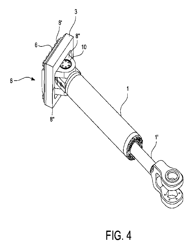
Figure 4 is a perspective view of the cylin-
der with a part of the frame of the vehicle.
Figure 5 is a perspective view of the cylin-
der without a part of the frame of the vehicle.
DETAILED DESCRIPTION
In Figures 1-3 a cylinder mounting arrange-
ment according to the invention has been shown in a
perspective view. This kind of hydraulic cylinder 1
(Fig.3) can be used for example as a steering cylinder
in mining vehicles, for example underground vehicles,
such as an articulated underground loader or truck. In
Figs. 1 and 2 only piston 1' of the cylinder 1 can be
seen. The vehicle has a front frame 2 and a rear frame
3 coupled to each other by an articulating pin 4. The
front frame 2 and the rear frame 3 are turned in rela-
tion to each other by the steering cylinder 1.
The invention is focused on the mounting of
the cylinder 1 to the rear frame 3. The mounting of
the piston 1' of the cylinder 1 to the front frame 2
may be conventional and shall not be explained in more
detail here.
For the mounting of the cylinder 1 to the ve-
hicle, the rear frame 3, preferably a corner box of
the rear frame 3, must have an opening 5 through which
CA 03184133 2022- 12- 22

WO 2022/042837
PCT/EP2020/073895
the cylinder 1 is inserted into its place and also re-
moved. In Fig.1 a position has been shown, where the
cylinder 1 has already been mounted and can be operat-
ed for steering purposes. The mounting to the rear
5 frame 3 has been tightened with mounting bolts 6 or
screws, which have been inserted through a front plate
8' of a mounting element 8 and screwed to the rear
frame 3. In this case the mounting bolts 6 are situat-
ed on the upper side and lower side of the opening 5.
There are totally 12 mounting bolts or screws, but the
amount can of course vary. The rear frame has of
course holes with inner threads to receive the mount-
ing bolts 6.
In Fig.2 a position has been shown, where the
mounting bolts 6 have been loosened and the piston 1'
has been released from the front frame 2 by removing
the fastening pin 7.
Further, in Fig.3 a position has been shown,
where the mounting bolts have been removed and most of
the cylinder 1 has been pulled out from the opening 5
of the rear frame 3. To assist this pulling a support
guide 9 can been mounted in the rear frame 3, along
which the cylinder I can be pulled out. This pulling
can be done manually. Of course, the same support
guide 9 is used when inserting a new cylinder 1 into
the frame.
After the cylinder end has been pulled out
from the opening 5, it can be supported for example by
a crane (not shown). Just before the whole cylinder 1
is out, the other end can also be supported by the
crane and then the whole cylinder I can be lifted
away.
CA 03184133 2022- 12- 22

WO 2022/042837
PCT/EP2020/073895
6
Figs.4 and 5 show the cylinder mounting of
the present invention in more detail. In Fig.4 the
reference number 3 refers to the rear frame. Of
course, only a part of it is shown in Fig.4. Reference
number 8 refers to the mounting element, which in-
cludes a front plate 8' and two ears 8" behind the
front plate 8', the ears being mounted around a cylin-
der pin 10. One ear 8" surrounds one end of the cyl-
inder pin 10 and the other ear 8" surrounds the other
end of the cylinder pin (10).
Fig.5 shows the same as Fig.4 except that the
frame part 3 has been removed. This clarifies how the
mounting bolts 6 are assembled in two rows, one above
the opening and one below the opening each row having
six mounting bolts.
It is obvious to a person skilled in the art
that with the advancement of technology, the basic
idea of the invention may be implemented in various
ways. The invention and its embodiments are thus not
limited to the examples described above, instead they
may vary within the scope of the claims.
CA 03184133 2022- 12- 22

Representative Drawing
A single figure which represents the drawing illustrating the invention.
Administrative Status

For a clearer understanding of the status of the application/patent presented on this page, the site Disclaimer , as well as the definitions for Patent , Administrative Status , Maintenance Fee  and Payment History  should be consulted.

Administrative Status

Title Date
Forecasted Issue Date Unavailable
(86) PCT Filing Date 2020-08-26
(87) PCT Publication Date 2022-03-03
(85) National Entry 2022-12-22

Abandonment History

There is no abandonment history.

Maintenance Fee

Last Payment of $100.00 was received on 2023-07-07


 Upcoming maintenance fee amounts

Description Date Amount
Next Payment if small entity fee 2024-08-26 $50.00
Next Payment if standard fee 2024-08-26 $125.00

Note : If the full payment has not been received on or before the date indicated, a further fee may be required which may be one of the following

  • the reinstatement fee;
  • the late payment fee; or
  • additional fee to reverse deemed expiry.

Patent fees are adjusted on the 1st of January every year. The amounts above are the current amounts if received by December 31 of the current year.
Please refer to the CIPO Patent Fees web page to see all current fee amounts.

Payment History

Fee Type Anniversary Year Due Date Amount Paid Paid Date
Application Fee $407.18 2022-12-22
Maintenance Fee - Application - New Act 2 2022-08-26 $100.00 2022-12-22
Maintenance Fee - Application - New Act 3 2023-08-28 $100.00 2023-07-07
Owners on Record

Note: Records showing the ownership history in alphabetical order.

Current Owners on Record
SANDVIK MINING AND CONSTRUCTION OY
Past Owners on Record
None
Past Owners that do not appear in the "Owners on Record" listing will appear in other documentation within the application.
Documents

To view selected files, please enter reCAPTCHA code :


To view images, click a link in the Document Description column. To download the documents, select one or more checkboxes in the first column and then click the "Download Selected in PDF format (Zip Archive)" or the "Download Selected as Single PDF" button.

List of published and non-published patent-specific documents on the CPD .

If you have any difficulty accessing content, you can call the Client Service Centre at 1-866-997-1936 or send them an e-mail at CIPO Client Service Centre.


Document
Description 
Date
(yyyy-mm-dd) 
Number of pages   Size of Image (KB) 
National Entry Request 2022-12-22 1 29
Declaration of Entitlement 2022-12-22 1 18
Representative Drawing 2022-12-22 1 13
Patent Cooperation Treaty (PCT) 2022-12-22 2 60
Description 2022-12-22 6 183
Claims 2022-12-22 2 68
Drawings 2022-12-22 5 110
International Search Report 2022-12-22 2 63
Correspondence 2022-12-22 2 46
National Entry Request 2022-12-22 8 220
Abstract 2022-12-22 1 17
Cover Page 2023-05-15 1 38