Note: Descriptions are shown in the official language in which they were submitted.
1
Ref. No.: SC-5693-CA
SCISSOR-LINK FOR ACTUATOR PULL-OPEN FUNCTION
CROSS-REFERENCE TO RELATED APPLICATION
[0001] This application claims the benefit of priority from
United
States Provisional Application No. 63/293,039, filed on December 22, 2021.
BACKGROUND
Field
[0002] The present disclosure relates generally to a scissor link
for
linking an actuator to a control lever and, more particularly, to a scissor
link for
linking a magnetically latched actuator to a manual control lever to manually
open
the switch.
Discussion of the Related Art
[0003] An electrical power distribution network, often referred
to as
an electrical grid, typically includes power generation plants each having
power
generators, such as gas turbines, nuclear reactors, coal-fired generators,
hydro-
electric dams, etc. The power plants provide power at a variety of medium
voltages
that are then stepped up by transformers to a high voltage AC signal to be
connected to high voltage transmission lines that deliver electrical power to
substations typically located within a community, where the voltage is stepped
down to a medium voltage for distribution. The substations provide the medium
voltage power to three-phase feeders including three single-phase feeder lines
that
carry the same current but are 120 apart in phase. A number of three-phase
and
single-phase lateral lines are tapped off of the feeder that provide the
medium
voltage to various distribution transformers, where the voltage is stepped
down to
a low voltage and is provided to loads, such as homes, businesses, etc.
Date Regue/Date Received 2022-12-19
2
Ref. No.: SC-5693-CA
[0004] Periodically, faults occur in the distribution network as
a result
of various things, such as animals touching the lines, lightning strikes, tree
branches falling on the lines, vehicle collisions with utility poles, etc.
Faults may
create a short-circuit that increases the load on the network, which may cause
the
current flow from the substation to significantly increase, for example, many
times
above the normal current, along the fault path. This amount of current causes
the
electrical lines to significantly heat up and possibly melt, and also could
cause
mechanical damage to various components in the substation and in the network.
Power distribution networks of the type referred to above often include
switching
devices, breakers, reclosers, interrupters, etc. that control the flow of
power
throughout the network and may be used to isolate faults within a faulted
section
of the network.
[0005] As part of its power distribution network, many utilities
employ
underground single-phase lateral circuits that feed residential and commercial
customers. Often times these circuits are configured in a loop and fed from
both
ends, where an open location, typically at a transformer, is used in the
circuit to
isolate the two power sources. Although providing underground power cables
protects circuits from faults created by things like storms and vegetation
growth,
underground cables still may break or otherwise fail as a result of corrosion
and
other things.
[0006] For a residential loop circuit of the type referred to
above
having two power sources, it is usually possible to reconfigure the open
location in
the circuit so that loads that are affected by a failed cable are fed by the
other
source and service to all of the loads is maintained. However, known processes
for identifying the location of a cable failure and the subsequent
reconfiguration of
the open location often result in long power restoration times because workers
are
required to physically go to the transformers to test for power and then
reconfigure
the transformers to change the open location.
[0007] It has been proposed to provide bushing well interrupter
devices employing vacuum interrupters and magnetic actuators in the existing
Date Regue/Date Received 2022-12-19
3
Ref. No.: SC-5693-CA
transformers for these types of loop circuits that provide automatic
protection,
isolation and restoration of underground residential cable loops and methods
to
switch cable segments without handling cable elbows. These bushing well
interrupter devices often have limited clearances to allow them to be
installed in
the existing transformers. The bushing well interrupter devices need to have a
mechanical system for opening the vacuum interrupter that can be used by a
local
service person to overcome the actuator/spring forces if needed. Various types
of
links are known that coupled the actuator to a manual control lever. These
links
must open the vacuum interrupter, but cannot be used to close the vacuum
interrupter or interfere with the normal closing of the vacuum interrupter,
thus
complicating the overall bushing well interrupter device design. In addition,
the
move toward smaller packaging of the bushing well interrupter devices is
making
the manual-open link a more difficult design challenge.
SUMMARY
[0008] The following discussion discloses and describes a switch
assembly that includes an outer housing having a cover at one end, a switch
provided within the housing at an end opposite to the cover, and a drive rod
coupled to the switch at one end. The switch assembly also includes an
actuator
assembly operable to magnetically latch the switch in a closed position, where
the
actuator assembly includes a cup member coupled to the drive rod opposite to
the
switch and an opening spring positioned within the cup member and being held
in
compression when the switch is latched closed, and where the cup member
includes a central opening. The switch assembly further includes a scissor
link
having a first leg and a second leg pivotally attached at a pivot point, where
one
end of the first and second legs extend into the central opening and are
rigidly
attached to the cup member and an opposite end of the first and second legs
extend through the cover, and where pulling the link away from the actuator
assembly breaks the magnetic latch and moves the drive rod to open the switch.
Date Regue/Date Received 2022-12-19
4
Ref. No.: SC-5693-CA
[0009] Additional features of the disclosure will become apparent
from the following description and appended claims, taken in conjunction with
the
accompanying drawings.
BRIEF DESCRIPTION OF THE DRAWINGS
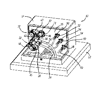
[0009] Figure 1 is an isometric view of a pad mounted transformer
employed in an underground residential loop circuit and including a pair of
bushing
well interrupter devices;
[0010] Figure 2 is a front view of the transformer shown in
figure 1;
[0011] Figure 3 is a cross-sectional type view of one of the
bushing
well interrupter devices in the transformer shown in figure 1;
[0012] Figure 4 is a broken-away, cross-sectional view of an
actuator
assembly in the bushing well interrupter device shown in figure 3;
[0013] Figure 5 is another broken-away, cross-sectional view of
an
actuator assembly in the bushing well interrupter device shown in figure 3;
and
[0014] Figure 6 is an isometric view of a scissor link used in
the
actuator assembly.
DETAILED DESCRIPTION OF THE EMBODIMENTS
[0015] The following discussion of the embodiments of the
disclosure
directed to a scissor link for linking a magnetically latched actuator that
magnetically opens and closes a switch to a manual control lever so as to
manually
open the switch is merely exemplary in nature, and is in no way intended to
limit
the invention or its applications or uses.
[0016] Figure 1 is an isometric view and figure 2 is a front view
of a
transformer 10 of the type that is mounted on a pad 12 that may be employed in
an underground single-phase lateral loop circuit that feeds residential and
commercial customers. The transformer 10 includes an enclosure 14 that houses
Date Regue/Date Received 2022-12-19
5
Ref. No.: SC-5693-CA
the transformer primary and secondary coils (not shown) and other electrical
components (not shown) of the transformer 10. A cover of the enclosure 14 has
been removed to expose a panel 16 in the enclosure 14. A connector bushing 20
positioned within and coupled to a bushing well 18 extends through the panel
16
that accepts a bushing well interrupter device 22 that connects a power line
24
having an elbow connector 26 to one side of the primary coil and a connector
bushing 30 positioned within and coupled to a bushing well 28 extends through
the
panel 16 that accepts a bushing well interrupter device 32 that connects a
power
line 34 having an elbow connector 36 to the other side of the primary coil,
where
the bushing well interrupter devices 22 and 32 are configured to provide
automatic
protection, isolation and power restoration of a lateral loop circuit without
handling
cable elbows. It is noted that the devices 22 and 32 are mirror images of each
other to accommodate spacing for the existing features on the transformer 10.
The
devices 22 and 32 each include an outer enclosure 40, a load-break interface
42,
a transformer interface 46 and a manual lever 48 for manually opening the
devices
22 and 32. A 120 V positive connector 50 is coupled to the secondary coil
through
a connector bushing 52 in the panel 16, a 120 V negative connector 54 is
coupled
to the secondary coil through a connector bushing 56 in the panel 16, and a
neutral
connector 58 is coupled to the secondary coil through a connector bushing 60
in
the panel 16. Distribution lines 62 are connected to the connectors 50, 54 and
58
to deliver low voltage power to the desired number of loads (not shown). In
this
example, the lines 24, 34 and 62 run underground.
[0017] Figure 3 is a cross-sectional view of the bushing well
interrupter device 22 showing one non-limiting example merely for illustrative
purposes. The components within the enclosure 40 are encapsulated within an
insulating medium 62, such as an epoxy, where many of the components are
conductors operating at the medium voltage potential. A Rogowski coil 64
measures current flow through the bushing well interrupter device 22. The
bushing
well interrupter device 22 includes a vacuum interrupter 66 having a vacuum
enclosure 68 defining a vacuum chamber 70, an upper fixed terminal 72
extending
Date Recue/Date Received 2022-12-19
6
Ref. No.: SC-5693-CA
through the enclosure 68 and into the chamber 70 and having a contact 74 and a
lower movable terminal 76 extending through the enclosure 68 and into the
chamber 70 and having a contact 78, where a gap 80 is provided between the
contacts 74 and 78 when the vacuum interrupter 66 is open. A bellows 82 allows
the movable terminal 76 to move without affecting the vacuum integrity of the
chamber 70. The movable terminal 76 is coupled to a drive rod 84 and
capacitors
88 provide voltage sensing and power line communications (PLC).
[0018] The bushing well interrupter device 22 also includes an
actuator assembly 90 that controls the drive rod 84 to open and close the
vacuum
interrupter 66. Figures 4 and 5 are broken-away cross-sectional views through
different lines of the bushing well interrupter device 22 illustrating the
actuator
assembly 90. The actuator assembly 90 includes an annular latching plate 92
having a central opening 94 through which a coupling rod 96 extends and is
coupled to the drive rod 84. The actuator assembly 90 also includes a stator
98
defining a central opening 100, where a magnetic plunger 102 is slidably
positioned within the opening 100. A coil 104 is positioned against the stator
98 in
the opening 100 and a series of permanent magnets 106 are positioned between
the plate 92 and the stator 98. A cylindrical cup member 110 is rigidly
secured to
the plunger 102 and includes an outer wall 112, an indentation 114 and a
central
cylinder 116 having an opening 118 defining a rim 120, where an outer chamber
122 is defined between the wall 112 and the indentation 114 and an inner bore
124 is defined within the cylinder 116. An opening spring 126 is provided
within the
chamber 122 and is positioned against the stator 98 and a compliance spring
128
is provided within the bore 124. A stop member 130 is provided within the
plunger
102 and is rigidly attached to the coupling rod 96. A cover 134 having a
central
opening 136 is bolted to the housing 40 and covers the actuator assembly 90.
[0019] The actuator assembly 90 also includes a scissor link 150
having a pair of scissor legs 152 and 154 that pivot relative to each other on
a pivot
pin 156. Figure 6 is an isometric view of the scissor link 150 separated from
the
bushing well interrupter device 22 showing the legs 152 and 154 in an open
Date Recue/Date Received 2022-12-19
7
Ref. No.: SC-5693-CA
position. As will be discussed in detail below, the scissor link 150 provides
a
mechanism by which the vacuum interrupter 66 can be manually opened by the
lever 48, but not manually closed. The leg 152 includes an upper half-
cylindrical
portion 160 and a lower body portion 162 separated by a tab 164. The upper
portion 160 includes a hole 166 and the lower portion 162 includes opposing
flanges 168 and 170 defining a slot 172. Likewise, the leg 154 includes an
upper
half-cylindrical portion 176 and a lower body portion 178 separated by a tab
180.
The upper portion 176 includes a hole 182 and the lower portion 178 includes
opposing flanges 184 and 186 defining a slot 188.
[0020] The legs 152 and 154 are pivoted closed (opposite to
figure
6) and then inserted through the opening 136 and into the opening 118 until
the
slots 172 and 188 lined up with the rim 120. The legs 152 and 154 are then
pivoted
open (shown in figure 6) so that the rim 120 is positioned within the slots
172 and
188 and the flanges 168 and 184 are positioned at one side of the rim 120 and
the
flanges 170 and 186 are positioned at the other side of the rim 120. The legs
152
and 154 are held in this position by inserting a rod 190 through the holes 166
and
182. An open/close indicator unit 194 including a central cylinder 196 and a
disk
198 having colored sections 200 in then installed by inserting the upper
portions
160 and 176 into the cylinder 196, where the cylinder 196 includes a helical
groove
(not shown) in which the rod 190 is positioned and some of the color sections
200
are green indicating the vacuum interrupter 66 is open and some of the color
sections 200 are red indicating the vacuum interrupter 66 is closed. A cap 202
including windows 204 is then positioned over the unit 194 and is bolted to
the
cover 134, where the sections 200 align with the windows 204.
[0021] A cam 210 including adjacent tabs 212 is rotated when the
lever 48 is raised. This causes the tabs 212 to engage the tabs 164 and 180,
which
causes the link 150 to pull on the cup member 110 with the bias of the opening
spring 126. This breaks the latch of the permanent magnets 106 and allows the
vacuum interrupter 66 to open under the force of the opening spring 126.
Lowering
the lever 48 rotates the cam 210 back to a home position, but does not cause
the
Date Recue/Date Received 2022-12-19
8
Ref. No.: SC-5693-CA
link 150 to be engaged. Movement of the link 150 in the cylinder 196 causes
the
rod 190 to ride in the helical groove, which causes the indicator unit 194 to
rotate.
When the unit 194 rotates the red sections 200 move out from under the windows
204 and the green sections 200 move under the windows 204 to provide an
indication that the bushing well interrupter device 22 is open.
[0022] The foregoing discussion discloses and describes merely
exemplary embodiments of the present disclosure. One skilled in the art will
readily
recognize from such discussion and from the accompanying drawings and claims
that various changes, modifications and variations can be made therein without
departing from the spirit and scope of the disclosure as defined in the
following
claims.
Date Regue/Date Received 2022-12-19