Note: Descriptions are shown in the official language in which they were submitted.
WO 2022/018044
PCT/EP2021/070180
OPTIMISED FIBRE REINFORCED FILMS
Field of the Invention
This invention relates to a tear resistant reinforced stretchable film. In
particular, the present
invention is directed to a reinforced thin film with controllable physical and
mechanical properties
such as tensile strength, elongation at break, tear resistance, coefficient of
friction and adhesion.
Articles according to the present invention may be silage, stretch film, pre-
stretched stretch film,
hood film or mulch film, and can be produced by known methods of extrusion or
co-extrusion such
as cast, blown and the like. The film is characterised by its significantly
lower weight when
compared to films known in the art with similar and/or improved physical and
mechanical
characteristics.
Background of the Invention
Reinforced stretchable films are used for many applications. In the example of
a stretch hood, as
described in W02006/076917 Al, the hood is formed from a biaxially oriented
tubular film having
a seam. In this application, the seam provides flexibility for adjusting the
size of the hood but
lacks the necessary structural reinforcement for use in demanding packaging
applications. In
the case of baling for age or hay, EP0923866 Al discloses a stretch film
imbued with a pest
deterrent, which increases the cost and the weight of the product
considerably.
Several cases are known in the art where the reinforcing phase is located in a
specific layer,
hence creating laminated structures in the film. In US2005/0175805 Al, a
plurality of fibres is
dispersed between two thermoplastic layers made during a blown process. This
fibre-reinforced
film, which is mainly formed into a bag, consists of an inner layer of
randomly dispersed fibres.
Accordingly, discontinuities in fibre volume fraction per unit length of film
occur, causing uneven
reinforcement across the film.
Co-extruded reinforced films for packaging have received increased attention
over the last few
years. US 4,536,362 discloses a longitudinally ribbed plastic film formed by
extrusion through a
specially designed die head. Similarly, in W02005/021240 Al the longitudinally
co-extruded
thicker regions are designed to strengthen the film. These documents aimed to
produce
inexpensive reinforced packaging film but suffer from uncontrollable thickness
fluctuations which
elicit variations in physical properties within one material. Furthermore, the
reinforcement is
CA 03184414 2022- 12- 28
WO 2022/018044
PCT/EP2021/070180
achieved by increasing the cross-section of sections in question (by
thickening them), rather than
by fundamentally enhancing the inherent properties of the material.
W02011/026954 discloses a thermoplastic film comprising a stretchable layered
base film and a
plurality of extruded elements located on the base film which form protrusions
away from the
plane of the base film. The material behaviour of the region between the film
and the reinforcing
fibre element is such that a mixed layer, comprising fibre element and base
film, exists between
the opposing layers of film and element material. This film exhibits a range
of beneficial physical
properties, such as tensile strength and tear resistance, but at a fraction of
the weight of other
films then known in the art.
Reinforced extendible systems, with longitudinal reinforcing strips fastened
to a film to increase
the mechanical strength of the film in the longitudinal direction, are already
available, even those
with low weight. Such reinforced systems need a secure coupling between the
base film and the
reinforcing strips applied atop the base film. This adds additional processing
steps during
production and thus additional cost. An important feature of reinforced
thermoplastic films is the
strength of the link between the base film and any reinforcing elements.
Strengthening of this
link/bond can be achieved by coupling agents or process steps designed to
enhance the quality
of the final product.
In certain embodiments, where thin flexible packaging with enhanced tensile
strength in the
machine direction is needed, existing systems have proposed either single wide
reinforcing strips
zo or folded/overlapped reinforcing elements. These, however, cause
significant increases in weight
and can encourage debonding of the elements from the film.
The use of stretch films of polyethylene for packaging or unitising goods is
known. For heavier
applications, and depending on the weight and size of goods, films with
different characteristics
(strength, thickness, tack, slip) are used.
For a film manufacturer, the major cost comes from the use of polyethylene as
a raw material. It
is therefore understood that the cost of producing packaging increases in
proportion to the
thickness of the film produced. Therefore, it is useful to decrease the
thickness of films used for
packaging in order to reduce production costs.
Additionally, the volume and weight of waste material produced during the
packaging or unitising
of goods is also dependent on the thickness of the film. Thus, reducing film
thickness in turn
reduces the volume and weight of waste material.
2
CA 03184414 2022- 12- 28
WO 2022/018044
PCT/EP2021/070180
The objective of the present invention is to overcome the problems mentioned
above, providing
a solution in the form of optimised reinforced stretch films.
Summary of the Invention
In accordance with a first aspect of the invention there is provided a
reinforced thermoplastic film
comprising:
a base film wherein the base film comprises a stretchable polyolefin material
comprising
one or more layers; and
a plurality of extruded reinforcing fibre elements;
io wherein the extruded reinforcing fibre elements are located on at
least one surface of the
base film;
wherein the extruded reinforcing fibre elements form fibre protrusions
relative to the
surface plane of the base film;
wherein at the location where each reinforcing fibre element is provided on
the base film,
an interface is formed comprising direct interactions between a base film
domain and a protrusion
domain;
wherein the base film domain is a domain of pure base film material and the
protrusion domain is
a domain of pure reinforcing fibre element material;
wherein the interface between the base film domain and the protrusion domain
is interrupted by
zo one or more discrete intermixed domains; wherein the intermixed domains
comprise a material
mixture comprising the base film material and the reinforcing fibre element
material and wherein
the one or more intermixed domains partially interrupt the direct interactions
at the interface
between the base film domain and the protrusion domain;
wherein the one or more intermixed domains have interfaces and direct
interactions with the base
and protrusion domains;
and
wherein the average thickness of the base film is less than the average
thickness of the fibre
protrusion.
In accordance with a second aspect of the invention there is provided a method
of producing a
thermoplastic film according to the first aspect of the invention.
3
CA 03184414 2022- 12- 28
WO 2022/018044
PCT/EP2021/070180
In accordance with a third aspect of the invention there is provided a use of
a thermoplastic film
according to the first aspect of the invention or of a product of the second
aspect of the invention
for packaging, silage applications, manual packing applications and mulch
applications.
In accordance with a fourth aspect of the invention there is provided a
thermoplastic film
obtainable from a method of producing a thermoplastic film.
The reinforced stretch film of the present invention is particularly suitable
for unitisation of goods,
e.g., packages, bales, silage or plants bearing sharp edges. It is also
suitable for use in mulching,
for example on arable land to suppress weeds and conserve water in crop
production and
landscaping. The reinforced stretch film of the present invention is
particularly suitable for use as
a silage film or a net replacement in silage applications, for example in
wrapping bales.
It is beneficial that a reinforced stretch film resists tearing or
catastrophic breakage during
wrapping or when the film is gathered from the soil following use as a plastic
mulch. The
geometrical features of the fibre protrusion of the reinforcing fibre element
as well as the shape
and the distribution of the domain of material mixture as defined in the
present invention improve
the tear resistance of the film during stretching or under stretched state
conditions. The degree of
tear resistance can be tailored to meet the different requirements of the end
film, which vary
depending on intended use. The propagation of tears across the film is
inhibited and delayed by
the reinforcing fibre elements, which allows the wrapping process to continue.
Hence, the integrity
zo of the reinforced stretch film and its packaging ability are maintained
without interrupting the
packaging procedure. For hand-wrapping the end user cuts said reinforced
stretch film by hand
after finishing the unitization of the goods. Similarly, for automated
wrapping lines the film is cut
at its edge by a suitable knife. Accordingly, the reinforced stretch film and
more specifically the
reinforcing fibre elements disposed thereon are not too strong, lest automated
or manual cutting
of the film be hindered.
A major limitation to the commercial uses of plastic film mulches is their
disposal. Removal of the
film from the field is time-consuming, requiring about 16 hours per hectare,
which increases
significantly if the film breaks into pieces during removal. If pieces of
plastic mulch film are left
behind in the field, having broken away from the main sheet during removal of
the mulch, this can
interfere with the root development of the subsequent crop. Normally the
useful life of plastic
mulching exceeds the duration of crop cycles and therefore plastic film
mulches require disposal
at the end of the season. The production and disposal of such plastic mulches
entail significant
environmental costs. The reinforced stretch film of the present invention
resists tearing and is
4
CA 03184414 2022- 12- 28
WO 2022/018044
PCT/EP2021/070180
designed to significantly facilitate the removal of plastic film mulches and
thereby reduce soil
contamination.
The present invention provides the abovementioned characteristics while
minimising overall
material usage and cost. The reinforced fibre stretch film can be thin, and
the one or more
reinforcing fibre elements are as effective as possible at a low overall
weight. These aspects have
significant additional benefits in terms of environmental and recycling
issues.
Brief Description of the Drawings
Further features and advantages of the reinforced stretch film according to
the present invention
become apparent from the illustrative description of exemplary embodiments
thereof taken in
conjunction with the accompanying drawings, wherein:
Figure 1 shows indicative shapes of fibre protrusions formed by reinforcing
fibre elements on base
films according to the present invention.
Figure 2 shows a schematic diagram of the relationship between reinforcing
fibre element, fibre
protrusion and the base film, emphasising the physical parameters relevant to
the present
invention and the domain types present at the interface.
Figure 3A shows three fibre protrusions of reinforced stretch films produced
under different
processing conditions.
Figure 3B shows schematic representations of three fibre protrusions of
reinforced stretch films
produced under different processing conditions, emphasising the physical
parameters relevant to
the present invention and the domain types present at the interface.
Figure 4 shows an analysis of the domains of material present along and around
the interface
formed between the fibre protrusion domain and the base film domain.
Figures 5A-50 show the physical and mechanical properties of reinforced fibre
films as a function
of maximum fibre protrusion height, Hprot max.
Figures 6A-60 show the physical and mechanical properties of reinforced fibre
films as a function
of maximum fibre protrusion width, VV
prot max.
5
CA 03184414 2022- 12- 28
WO 2022/018044
PCT/EP2021/070180
It is noted that the figures are not drawn to scale and represent only
schematic illustrations of
systems. They do not represent the actual proportions of objects according to
the present
invention.
DETAILED DESCRIPTION OF THE INVENTION
All preferred embodiments and features according to the present invention
should be considered
as disclosed in combination with other preferred embodiments and features of
the invention.
The preferred features and values below are generally given with respect to
each individual fibre
element. However, these values are equally applicable across the plurality of
fibre elements,
where they then may refer to the mean average value for the feature
referenced.
In the present invention, a plurality of extruded reinforcing fibre elements
is disposed on at least
one surface of the base film. The extruded reinforcing fibre elements form
fibre protrusions relative
to the surface plane of the base film. Each fibre protrusion comprises a
protrusion domain (PD)
of pure fibre element material. At the location where each reinforcing fibre
element is disposed on
the base film, i.e., below the fibre protrusion, the base film comprises a
base film domain (BD) of
pure base film material.
The base film domain is generally underneath the fibre protrusion domain.
An interface is formed between the domain of pure base film material and the
domain of pure
reinforcing fibre element material at the location where each reinforcing
fibre element is located
on the base film. The interface comprises direct interaction between the base
film and fibre
zo protrusion domains. This direct interaction is interrupted by one or
more domains of material
mixture comprising the base film material and the fibre element material.
These domains may be
referred to as intermixed domains. The intermixed domains (ID) comprise a
material mixture
comprising the base film material and the reinforcing fibre element material.
Such intermixed
domains form following the transfer of material from the protrusion domain of
pure fibre element
material and from the base film domain of pure base film material. The
interaction between the
PD and BD domains means that the interfacial mixing is not continuous and
complete across the
interface formed between the domain of pure base film material and the domain
of pure reinforcing
fibre element material ¨ in other words, the interfacial mixing is
discontinuous. The interface
between the domain of pure base film material and the domain of pure
reinforcing fibre element
material may thus be referred to as "discontinuous".
6
CA 03184414 2022- 12- 28
WO 2022/018044
PCT/EP2021/070180
The intermixed domains are discrete in the sense that they form individual
domains and do not
extend along the entire length of the interface formed between the domain of
pure base film
material and the domain of pure reinforcing fibre element material. The one or
more intermixed
domains have their own interfaces and direct interaction with both the base
film and fibre
protrusion domains.
There may be more than one domain of intermixed material across the
discontinuous interface
formed between the domain of pure base film material and the domain of pure
reinforcing fibre
element material. For instance, there may be two, three, four, five or more
than five discrete
intermixed domains at the interface between the protrusion and base film
domains.
The present invention addresses shortcomings with the prior art. When
reinforcing fibre elements
are freshly extruded and deposited onto a base film, extensive heat may be
transferred from the
reinforcing fibre element to the base film. The use of heat is necessary
because, in combination
with applied pressure, it ensures good wetting of the surface of the fibre
element and the surface
of the base film. However, if the heat transfer is extensive, the heat (along
with the applied
pressure) can create edge defects. These may locally weaken the reinforced
fibre film. Tear
propagation may then be initiated at this point, leading to catastrophic
failure of the product. On
the other hand, if there is not enough heat or pressure, delamination of the
fibre protrusion and
the base film may occur. The tear might then propagate underneath the fibre
protrusion causing
again catastrophic breakage of the film. Therefore, the effective welding of
fibre protrusion to the
zo base film requires controlled use of heat and pressure. This results in
discontinuous interfacial
mixing and formation of the interfaces discussed above.
In more detail, between the fibre protrusion and base film domains, an
interface is formed, where
the interface comprises direct interactions between the base film domain and
fibre protrusion
domain. The interface comprises on the one side pure fibre protrusion material
and on the other
side pure base film material. The interface between pure reinforcing fibre
element material and
pure base film material is intermittently interrupted by one or more discrete
domains, otherwise
referred to as intermixed domains. These domains interrupt the direct
interaction of the fibre
protrusion and base film domains at these locations. The intermixed domains
comprise both
reinforcing fibre element material and base film material as a result of
material transfer from the
BD and PD domains through the interface.
7
CA 03184414 2022- 12- 28
WO 2022/018044
PCT/EP2021/070180
Preferably, the intermixed domains are located away from the perimeter of the
fibre protrusion,
i.e., away from the outer edge contact points, Cl and 02. The intermixed
material domains are
preferably located towards the interior of each fibre protrusion.
The intermixed domain boundaries are surrounded by pure reinforcing fibre
element material and
pure base film material. In other words, the intermixed domains form
interfaces with both the
protrusion domain and the base film domain.
The size, number, and shape of each intermixed domain depends on the
reinforcing fibre element
material and base film material compatibility, applied temperature, applied
pressure, reinforcing
fibre element mass, base film thickness, extrusion speed etc. These factors
can all be varied to
io arrive at the desired degree of intermixing within the intermixed
domain.
The reinforced thermoplastic film of the invention may comprise further
domains of intermixed
material which are not located at the interface between the fibre protrusion
and base film domains.
The boundaries of these intermixed domains may thus be totally surrounded by
pure base film
material or pure reinforcing fibre element material.
The location of the various domains can be seen for example in Figure 2.
Underneath the fibre
protrusion is identified a contact plane, defined as the plane formed between
the outer edge
contact points Cl and 02 extending laterally relative to the fibre protrusion.
The cross-sectional
planes are the planes perpendicular to the contact plane passing through the
points Cl and C2
and orthogonally crossing the base film.
zo The extruded base film is the film used as a base, onto which to the
extruded reinforcing fibre
elements are placed.
The intermixed domains are located in such a way to prevent pure reinforcing
fibre element
material and pure base film material from coming into contact at certain
locations across the
discontinuous interface.
Preferably, in the vicinity of the outer edge contact points (Cl and C2) there
is direct contact of
pure base film material and pure reinforcing fibre element material.
Thus, in a typical film of the invention, there is generally a bottom layer of
base film material, a
top layer of reinforcing fibre element material, and a discontinuous interface
between the top and
bottom layers. The areas or regions of interfacial mixing may be targeted to
certain locations
across the interface, e.g., to the interior or central portion of the fibre
protrusion, away from the
boundaries of the contact between the reinforcing fibre element and the base
film.
8
CA 03184414 2022- 12- 28
WO 2022/018044
PCT/EP2021/070180
A portion of each reinforcing fibre or reinforcing fibre-like element material
forms an interfacial
mixture with the base film material. Preferably, less than 50%, more
preferably less than 20%,
most preferably less than 10% by weight on average of each reinforcing fibre
or reinforcing fibre-
like element material forms an interfacial mixture with the base film
material. This ensures good
mixing of the polymeric materials, hence good bond strength of the reinforcing
fibre elements to
the base film. This yields high tear resistances compared to base films in
which strengthening
elements are mounted or bonded to their surface, for example, by adhesive.
Preferably, more than 30% of the maximum height of the reinforcing fibre
element (measured
before the element is applied to the base film) protrudes above the film
surface, more preferably
more than 50% and most preferably more than 80% of the maximum height is
retained/remained.
The reinforced thermoplastic film preferably has a weight of between 4.0 g/m2
and 100.0 g/m2,
more preferably 6.0 g/m2 and 60.0 g/m2, most preferably 10.0 g/m2 and 20.0
g/m2.
Preferably, the reinforcing fibre elements of the reinforced thermoplastic
film of the present
invention have a weight in total which is less than 50% the weight of said
base film, or more
preferably less than 30% the weight of said base film, or most preferably less
than 20% the weight
of said base film. Said reinforcing fibre elements preferably have a basis
weight of less than 1
g/cm2, more preferably less than 0.1 g/cm2, most preferably less than 0.01
g/cm2.
A contact plane may be defined as the plane connecting the outer edge contact
points Cl and
C2. These points reside on the boundary of contact between the reinforcing
fibre element and the
zo base film. The one or more domains of intermixed material may be formed
above, below or
crossing the contact plane.
The number and size of the intermixed domains (i.e., the amount of interfacial
mixing) can be
controlled by varying the temperature and/or pressure at which the reinforcing
fibre elements are
applied to the base film. Other factors which can be varied include the
reinforcing fibre element
mass, base film thickness and extrusion speed, and so on.
For example, the magnitude of the compression of the reinforcing fibre element
onto the base
film, and time of compression, can both be controlled in order to arrive at
specified degrees of
interfacial mixing across the interface between the protrusion and base film
domains. These
variables can also be used to control the height and/or width of the fibre
protrusion.
Alternatively, where the magnitude of compression of the reinforcing fibre
element onto the base
film is low, such that the pressure is low, this may result in a greater
maximum height of the fibre
9
CA 03184414 2022- 12- 28
WO 2022/018044
PCT/EP2021/070180
protrusion (H prot max) and the presence of discrete domains of interfacial
mixing of the materials
from the base film and reinforcing fibre element, respectively.
The amount of interfacial mixing can be controlled along the interface with
the maximum height
and/or maximum width of the fibre protrusion, in order to optimise the
strength of the film. This
control can lead to unexpected improvements in tear energy and tensile
properties.
The plurality of reinforcing fibre elements comprises at least three
reinforcing fibre elements which
are configured to reinforce the base film. Each element forms its own
individual protrusion
domains with the base film.
The interface of each fibre protrusion with the base film is typically curved.
In other words, when
the film is viewed through its cross-section (alternatively referred to as the
vertical dimension, z),
a curved interface is formed between the fibre protrusion and the base film.
The base film under the fibre protrusion comprises a top (interfacial surface)
and bottom surface
where either may deflect (or bend) in the vertical dimension z following the
curvature of the
interface.
The localised bending may be due to the contact and bonding of the one or more
reinforcing fibre
elements with the base film and the formation of domains. The way in which one
or more
reinforcing fibre elements interact with the base film and the distribution of
the intermixed domains
are important. The degree of the curvature, the level of base film-reinforcing
fibre element
material mixing, the extent of intermixing, the maximum height, the maximum
width, and the angle
zo of the fibre protrusion can be controlled to give optimal strength to
the stretch film.
The means by which the plurality of reinforcing elements interact with the
base film and the shape
of the interface formed between the outer edge contact points Cl and C2 of the
fibre protrusion
formed on the base film are important. The degree of curvature, the extent to
which the fibre
protrusion and base film materials intermix, and the height of the fibre
protrusion can be controlled
and refined in order to enhance the physical and mechanical properties (e.g.,
strength, resistance
to tearing) of the optimised reinforced thermoplastic film.
In the invention, extruded reinforcing fibre elements are fibres which are
extruded and placed on
the top of the surface of the base film to provide resistance to tear
propagation. The reinforcing
constituents are fibres or fibre-like elements. "Reinforcing Fibre" or
"reinforcing fibre-like" has the
meaning of being elongated elements wherein the cross section of the element
has a width in the
same order of magnitude in comparison to the height of the element.
CA 03184414 2022- 12- 28
WO 2022/018044
PCT/EP2021/070180
The terms "Reinforcing fibre" and "reinforcing fibre-like" are interchangeable
as used herein.
The plurality of reinforcing fibre elements of a reinforcing fibre element
material is configured to
reinforce the base film, wherein the reinforcing fibre elements are provided
at least on one surface
of the base film and form an elevated area of material on at least one surface
of the base film,
which forms the "fibre protrusion". The maximum height and maximum width of
the fibre
protrusion, and the ratio of the maximum height to maximum width, are all
important.
When dimensions are referenced herein, they may apply to each individual
reinforcing fibre
element or fibre protrusion, the reinforcing fibre elements or fibre
protrusions as a whole, or
alternatively, be the mean average dimension for all the reinforcing elements
or fibre protrusions
across the film.
The fibre protrusions extend above the plane of contact formed between the two
outer contact
points C1 and C2 typically by more than 60 pm, preferably by more than 100 pm,
more preferably
by more than 140 pm, most preferably by more than 200 pm. This dimension may
alternatively
be referred to as the height maximum (H prat max) of the fibre protrusion,
being the maximum
straight-line distance extending from the distalmost point of the fibre
protrusion to the contact
plane, the straight line being perpendicular to the plane of the contact. The
contact plane
connects in straight lines the two outer edge points of contact between fibre
protrusion and base
film. Hprot max is preferably in the range 60 pm to 200 pm and is most
preferably in the range 100
pm to 180 pm.
zo The width of the fibre protrusions is generally less than 1000 pm, more
preferably less than 600
pm, most preferably less than 350 pm. The width maximum (
,Wprot max) of the fibre protrusion is the
maximum width of a fibre protrusion from one side to the other, said
measurement running parallel
to the plane of contact. VVprot max is preferably in the range 200 to 260 pm
and is most preferably
in the range 200 to 240 pm.
The contact width is the distance as measured from the outer edge contact
point Cl to the outer
edge contact point 02 along the contact plane, i.e., in a cross-section of the
protrusion and lying
perpendicular to the height of the protrusion.
The fibre protrusions preferably have a contact width of less than 1100 pm,
preferably less than
700 pm, more preferably less than 400 pm.
The ratio of the height to the width of the reinforcing fibre elements prior
to application to the base
film may be in the range 3:1 to 1:3, more preferably in the range 2:1 to 1:2,
more preferably in the
11
CA 03184414 2022- 12- 28
WO 2022/018044
PCT/EP2021/070180
range 1.5:1 to 1:1.5, such as in the range of about 1:1. This ratio may change
after the reinforcing
fibre elements are applied to the base film. The ratio of the largest axis to
the smallest axis of the
cross-section of the reinforcing fibre elements may be less than 3:1, more
less than 2:1, more
preferably less than 1.5:1, such as about 1:1. The ratios expressed herein are
in the form x:y,
which denotes x-to-y, i.e. that for x items, there are y items. For example, a
height-to-width ratio
of 1:4 denotes that each 1 unit of height is accompanied by 4 units of width,
hence the value of
height is 25% of the value of width. This percentage can also be expressed in
decimal or fractional
form, such that 1:4 = 25% = 0.25. This geometry distinguishes the reinforcing
fibre or reinforcing
fibre-like elements for example from strips, bands, ribbons or tapes as
reinforcement elements,
io which have a large width in comparison to the height of the strip. The
advantage of such a
reinforcing fibre or reinforcing fibre-like geometry is the smaller material
consumption for a given
height, and more tuneable properties of the resultant materials. Said
reinforcing fibre or reinforcing
fibre-like elements are distinguished from dots or spots.
Preferably, after application to the base film, the height of the fibre
protrusion is substantially of
the same size as its width, although generally the height is slightly less
than the width. In some
embodiments, where the reinforcing fibre element has been deposited and bonded
to the base
film, the fibre protrusions preferably have a ratio of maximum height from the
plane of contact to
maximum width of more than 0.1, preferably more than 0.2, more preferably of
more than 0.33,
still more preferably of more than 0.4 or 0.5, even more preferably of more
than 0.6 and most
zo preferably of more than 0.80, or even more than 1Ø
For a particular element, the ratio Hprot max/Wprot max is preferably in the
range 0.60 to 1.00,
preferably in the range 0.65 to 0.90, most preferably in the range 0.70 to
0.80. This results in fibre
protrusions which are taller and narrower than those reported previously.
The fibre protrusions do not cover the entirety of the film, instead the
percentage of the surface
area of the film covered is generally below 51%, or below 45%, more preferably
below 40%, most
preferably below 35%.
The diameter of the reinforcing fibre elements is preferably between 30 pm and
1000 pm, more
preferably between 50 pm and 500 pm, most preferably between 100 pm and 350pm.
The
maximum average diameter of the reinforcing fibre elements may vary by no more
than 75%,
preferably by no more than 50%, more preferably by no more than 25%, most
preferably by no
more than 10%, from the minimum average diameter of the reinforcing fibre
elements.
12
CA 03184414 2022- 12- 28
WO 2022/018044
PCT/EP2021/070180
The ratio of the average height to the average length of said reinforcing
fibre element of the current
invention is in the range of 1:500 to 1:10000000, preferably in the range
1:1000 to 1:1000000,
most preferably in the range 1:10000 to 1:100000.
Preferably, where an extrusion process is used to form the reinforcing fibres
or reinforcing fibre-
like elements, the reinforcing fibres or reinforcing fibre-like elements have
a substantially circular
cross-section. This cross-section may become more oval in cross-section as the
reinforcing fibre
element s are applied to the base film. Thus, preferably the reinforcing fibre
elements have a
substantially circular cross section prior to application to the base film. In
contrast, once the
reinforcing fibre element has been applied to the base film, particularly
where pressure has been
applied to it, the fibre protrusion preferably has a more oval or elliptical
cross-section. Such fibre
protrusions may even have an eye shaped cross-section. Typical fibre
protrusion shapes are
shown in Figure 1.
The protrusion angle is the supplementary angle of the angle formed between
the tangent to the
fibre protrusion and the plane of contact at the outer edge contact point. The
outer edge contact
points are the two points where the reinforcing fibre element makes contact
with the upper or
lower surface of the base film. The tangent touches the outline of the fibre
protrusion at one point
and crosses the plane of contact at the outer edge contact point. The contact
plane is defined as
the plane which connects the outer edge contact points Cl and C2 and is
located under the fibre
protrusion. Cl and C2 are connected by a straight line.
zo The protrusion angle is then calculated by subtracting the supplementary
angle from 180 degrees.
In practice, it is often this measurement which is taken when seeking to
measure a protrusion
angle, as this can be measured by using standard optical techniques.
There are two protrusion angles, PA1 and PA2 (as illustrated in the figure 2),
which refer to the
supplementary angles of the angles formed on either side of the fibre
protrusion when viewed
along its cross-section. The two protrusion angles either side of the element
are not necessarily
the same. This may also correspond to a different degree of interfacial mixing
at each side of the
element. The angle may relate to the degree of penetration of reinforcing
fibre element material
into the base film material, i.e., the degree of interfacial mixing. A smaller
angle may indicate less
intermixing, but the fibre protrusion may provide a larger barrier to tear
propagation. Large angles
may indicate a shallower fibre protrusion, which may have more interfacial
mixing below it.
Each protrusion angle is preferably independently selected from a value in the
range 10 degrees
to 170 degrees, more preferably in the range 40 degrees to 140 degrees, more
preferably in the
13
CA 03184414 2022- 12- 28
WO 2022/018044
PCT/EP2021/070180
range 60 degrees to 120 degrees, most preferably around 90 degrees. In a
preferred
embodiment, the protrusion angles PA1 and PA2 are substantially identical,
i.e., the sides of the
fibre protrusion are preferably symmetrical.
In a preferred embodiment, the difference between the two protrusion angles
PA1 and PA2 of
each fibre protrusion is less than 90 degrees, preferably less than 60
degrees, more preferably
less than 30 degrees, most preferably less than 10 degrees.
The cross-sectional shape of the reinforcing fibre element is important. After
the deposition of
the reinforcing fibre elements on the base film the interface formed between
the fibre protrusion
domain and the base film domain is typically curved, preferably convex or
concave.
The reinforcing fibre elements may be positioned straight, curved, waved,
zigzag, spiral, in the
form of circles or can take any other configuration or contour.
Mixtures of reinforcing fibre element cross-sectional shapes may also be used.
The related cross-
sectional shapes of the reinforcing fibre elements have in practice, obtuse,
trimmed, and rounded
edges. The cross-sectional area may vary along the fibre protrusion, for
example by altering the
draw-ratio of the reinforcing fibre element during a continuous deposition
process alters the
deposited fibre mass. Round or oval cross sections are preferable. The cross-
sectional shape
of the reinforcing fibre elements may change before and after their
positioning on the base film.
In other embodiments the cross-sectional shape of the fibre protrusion is
round, square, elliptical,
rectangular or lenticular.
zo The cross-sectional shape may vary over the length of the fibre
protrusion. Processing of the
reinforcing fibre elements can give extra performance to the final article.
The reinforced stretch film of the present invention comprises a base film
which is preferably an
extruded mono or multilayered stretchable or pre-stretched film. The
thermoplastic film of the
current invention is reinforced with fibre elements which are applied to the
film and form fibre
protrusions once applied. The result is controllable properties such as,
tensile strength, elongation
at break, tear resistance, coefficient of friction and weight per square
metre, through the tuneable
properties of the fibre protrusion. Such a reinforced thermoplastic film is
ideally suited for use in
pallet and food wrapping, product unitization, baling hay and barrier film,
and agricultural
applications such as mulching. Said thermoplastic film preferably does not
apply to any garment
or disposable garment applications.
14
CA 03184414 2022- 12- 28
WO 2022/018044
PCT/EP2021/070180
The base film and the reinforcing fibre elements may be pre-stretched by at
least 10%, preferably
by at least 50%, more preferably by at least 100%, most preferably by at least
200%.
The base film may be perforated or non-perforated. The lateral edges of the
base film may be
hemmed or unhemmed.
The base film may comprise polyethylene, polypropylene, polyisobutylene,
polybuty1-1-ene, poly-
4-methylpent-1-ene, polyisoprene, polybutadiene and/or mixtures and copolymers
thereof.
Preferably the base film comprises ethylene-based polymers.
The said base film is preferably not an elastic non-woven or spun-bonded type.
When the base film is a nnultilayer film it may be nnultilayer symmetrical,
for example, ABCBA
io structure or asymmetrical, for example ABCDE structure, which are
further described in
W02011/026954.
In the invention, the base film may have an ABC, ABA, ABCBA or ABCDE
structure, wherein
ABCDE are layers having different compositions and/or thicknesses, with the
exception that layer
D may be the same as layer B.
For the above ABC layer structure, the layer A is preferably a slip layer, the
layer B is preferably
a core layer, and the layer C is preferably a cling layer. For the above ABCDE
layer structure, the
layer A is preferably a slip layer, the layer B is preferably an intermediate
layer, and the layer C
is preferably a core layer, layer D is an intermediate layer and layer E is
preferably a cling layer.
The core layer of the base film may comprise polypropylene and other polymers.
As used herein, "a different type of layer" is used to denote one or more
different chemical or
physical characteristic of the layer selected from the group including
thickness, density, melt
index, chemical composition, polymer type, major melting peak, crystallisation
temperature, and
the like.
Preferably, the reinforced thermoplastic film of the present invention
comprises a base film which
is an extruded multilayered stretchable or pre-stretched film. The base film
may have 3+2n layers,
where n is a natural number such as 0, 1, 2, 3, 4 and so on. Preferably, the
base film has 3, 5, 7,
9, 11, 15, 17, 19, 21, 23, 25 or 27 layers, more preferably 3,5 or 7 layers,
more preferably 3 or 5
layers, most preferably 5 layers.
CA 03184414 2022- 12- 28
WO 2022/018044
PCT/EP2021/070180
Preferably, the base film has a symmetrical (ABA for a three-layer film; ABCBA
for a five-layer
film) structure, wherein each of A, B and C represent a different type of
layer in the multilayer film.
Preferably the stack of the multilayer is symmetric with regards to the
central layer.
A further preferred base film is one having a three-layer asymmetric structure
(for example ABC),
wherein each of A, B and C represent a different type of layer in the film.
A further preferred base film is one having a five-layer asymmetric structure
(for example ABCDE),
wherein each of A, B, C, D and E represent a different type of layer in the
film. In the ABCDE
structure, layers B and D may be made of the same composition and/or be of the
same thickness.
For the above ABCDE layer structure, B, C and D can comprise nanolayers. The
technology of
io producing nanolayers is described in more detail in US2009/0104424.
Preferably, the fibres of the present invention (which may be used in any of
the embodiments or
aspects disclosed herein) comprise or consist of co-extruded fibres. The
fibres of the present
invention are preferably bi-component fibres having a shell/core structure,
which are further
described in W02011/026954.
The deposited fibre elements may possess slip characteristics in order to
compensate for the
tacking characteristics of the base film. In one embodiment the tacking
characteristics denote the
tacking of the material when it is in contact with itself. The slip
characteristic of the fibre elements
facilitates the unwinding of the film from its roll more easily.
Preferably, the width of said base film is less than or equal to 1500 mm,
preferably is less than or
zo equal to 1000 mm, more preferably is less than or equal to 750 mm, most
preferably is less than
or equal to 500 mm.
Preferably, the reinforced thermoplastic film of the present invention
comprises a base film which
is an extruded nnultilayered stretchable or pre-stretched film. These are
further described in our
previous patent publication W02011/026954. The reinforcing fibre elements and
the base film
materials may comprise polymers or copolymers, preferably synthetic polymers.
Preferably the
polymers are polyolefins or non-polyolefins such as polyamides or polyesters.
Mixtures of
different polyolefins or mixtures of polyolefins with non-polyolefins can also
be used. In an
embodiment, the base film and/or the fibre elements comprise polypropylene.
Where the base film and the fibre elements are made from the same chemical
material, the
physical attributes of the base film and the fibre elements may differ.
16
CA 03184414 2022- 12- 28
WO 2022/018044
PCT/EP2021/070180
The film of the present invention may be produced by cast and blown extrusion
methods, which
are further described in W02011/026954.
The reinforcing fibre elements are preferably bonded onto the base film
through heat fusion.
During deposition, the reinforcing fibre elements are generally at a
temperature higher than room
temperature and close to their crystallisation range, that is, preferably 1-
100 C above their
crystallisation point, more preferably 1-80 C, more preferably 10-60 C, more
preferably 20-50 C.
The crystallisation point may be determined by means of Differential Scanning
Calorimetry with a
heating rate of 10 C/min.
During the process, the base film material and the reinforcing fibre element
material form a
connection on a molecular level and are interpenetrated at the interface
between the pure base
film material and the pure reinforcing fibre element material. Thus, at the
location where the
reinforcing fibre elements are provided on the base film, a discontinuous
interface is formed
between pure reinforcing fibre element material and pure base film material.
Along this interface,
one or more domains of a material mixture comprising the base film material
and the fibre element
material is present between a domain of pure base film material and a domain
of pure reinforcing
fibre element material so as to partially separate the domain of pure
reinforcing fibre element
material and the domain of pure base film material. The said reinforcing fibre
elements are
introduced onto the base film to partially wet the surface of the base film,
to interlock or
interpenetrate with said base film material, and to transfer pure reinforcing
fibre element material
zo to the pure base film material. Accordingly, the interface between
reinforcing element and base
film is comprises direct contact between pure fibre element material and pure
base film material
and is interrupted by one or more domains of intermixed base film material and
fibre element
material. In this way, a film with an increased tear resistance and strength
can be achieved.
Furthermore, the optimised fibre films according to the present invention have
a decreased risk
of the protrusions becoming detached from the base films compared to prior art
films.
It is understood that in the case where the base film and the reinforcing
fibre elements are made
of the same material, no mixture of different materials is formed.
Nevertheless, interpenetration
of the polymer chains occurs. The term "pure base film material" means there
is less than 10%
by weight of the fibre element material in the base film domain, preferably
less than 5% by weight,
more preferably less than 1% by weight, more preferably less than 0.1% by
weight of the
reinforcing fibre element material in the domain.
17
CA 03184414 2022- 12- 28
WO 2022/018044
PCT/EP2021/070180
The term "pure fibre element material" means there is less than 10% by weight
of the base film
material in the base film domain, preferably less than 5% by weight, more
preferably less than
1% by weight, more preferably less than 0.1% by weight of the base film
material in the domain.
Simple application of heat during bonding of a reinforcing element (such as a
strip) onto a base
film does not automatically create an intermixed domain sufficient to
withstand tear propagation,
for example where either the temperature is insufficiently high or the
exposure time to the heat is
insufficient. By depositing reinforcing fibre or reinforcing fibre-like
elements onto the base film
which themselves act as heat sources, said reinforcing fibre element material
crystallise from the
melt upon positioning them onto said base film, thereby ensuring the heat
required to achieve a
io sufficiently strong intermixed domain. Preferably the reinforcing fibre
elements are extruded
directly onto the base film. The phrase "are extruded directly" means the
fibres are placed on the
base film within 30 minutes of their extrusion, preferably within 20 minutes,
more preferably within
2 minutes, more preferably within 1 minute, more preferably within 10 seconds,
more preferably
within 5 seconds, more preferably within 1 second. Preferably, the process is
continuous.
In one embodiment, the fibre protrusions are annealed onto the base film.
The method for producing the reinforced thermoplastic film of the present
invention preferably
involves direct extrusion of about 1:1 to 1.5:1 (ratio of width to height)
reinforcing fibre elements
onto the thin base film, wherein said base film may be extruded or direct
extruded. Said
reinforcing fibre elements are preferably crystallized onto the base film,
preferably maintaining
zo their ratio width to height dimension. The average thickness dimension
of said thin base film is
preferably less than the average height dimension of said fibre element. At
the deposition, a
thermoplastic film intermediate is produced which may further follow a cooling
procedure,
supplying the thermoplastic film of the present invention. In this case said
thermoplastic film has
similar outer dimensions to said thermoplastic film intermediate. Preferably,
the reinforcing fibre
elements are pressed shortly after their contact with the base film or most
preferably at the contact
with the base film such as the ratio width to height of the reinforcing fibre
element is altered. In
that case the produced thermoplastic film intermediate differs from said
thermoplastic film of the
present invention regarding the outer dimensions.
In the present invention, placement of the reinforcing fibre element is
carried out, with the fibre
ideally 1-100 C above its crystallisation point, more preferably 1-80 C, more
preferably 10-60 C,
more preferably 20-50 C. The reinforcing fibre itself is a hot element which
delivers heat directly
to the surface of the base film, resulting in fast, efficient, pointed and
controllable heat delivery
18
CA 03184414 2022- 12- 28
WO 2022/018044
PCT/EP2021/070180
which is not limited to time contact. Accordingly, intermixing occurs at the
interface of reinforcing
fibre element and base film, resulting in one or more domains of mixed
material comprising
reinforcing fibre element material and base film material, which does not
extend along the entire
length of the interface.
This joining mechanism of the base film and the reinforcing fibre element(s)
provides sufficient
connection between the reinforcing fibre element(s) and base film, without the
need for the large
contact areas between the element and film which are normally required for
broader
reinforcement elements such as strips, bands or tapes. Further local debonding
is less likely with
fibre protrusions in contrast to strips, as the fibre protrusions do not have
the same internal
to stresses as strips. When strips shrink, they become debonded from the
base film, but the fibre
protrusions do not.
The joining mechanism of the reinforcing fibre element and the base film has
the additional
advantage that when interfacial mixing occurs it is not necessary to embed the
reinforcing fibre
elements into the base film. In the present invention, it is also not
necessary to ensure that
continuous interfacial contact is present across the cross-section of the
element.
The thermoplastic base film is extruded and may be further processed by blown
or cast
processing. The deposition may be performed on the base film wherein in the
base film is
preferably in a molten or at least partially molten state or in the solid
state.
Pressure may be applied to the reinforcing fibre element after deposition on
the base film for
zo better fixation of the fibre protrusion on the base film. In addition,
the pressing process may be
used to define the cross-section form of the fibre protrusion and the degree
of interfacial mixing.
This may be achieved by using pressing means for forming the corresponding
cross-section. The
pressure may be applied by means of a cylinder which can apply pressure to the
fibre protrusion
at the deposition point. Said cylinder may adjust the height of the fibre
protrusion through its fixed
position from said base film.
The base film used in this invention is typically substantially a thin film,
the average thickness
thereof being preferably in the range 4 pm to 50 pm, more preferably 5 pm to
30 pm, more
preferably 6 pm to 30 pm, most preferably 6 pm to 25 pm, even more preferably
10 pm to 25 pm.
In an embodiment, the thickness of the base film is in the range 15 pm to 45
pm.
In certain embodiments the lateral edges of the film, along the machine
direction, of said base
film are hemmed.
19
CA 03184414 2022- 12- 28
WO 2022/018044
PCT/EP2021/070180
The reinforcing fibre elements and consequently also the fibre protrusions
and/or the base film
may contain additives. The use of additives may impart the reinforcing fibre
elements, and hence
the fibre protrusions also, or the complete reinforced thermoplastic film,
with specific properties.
The additives in the reinforcing fibre elements and the fibre protrusions
and/or in the base film
may comprises reinforcing fillers, antioxidants, UV stabilizers, antimicrobial
substances, colouring
compounds, tacking inhibitors, tacking intensifiers, corrosion inhibitors,
humidity trappers, thermal
history indicators, anti-static agents, plant growth promoters and/or weed
killer agents or mixtures
thereof. Suitable volatile corrosion inhibitors may be compounds such as
inorganic nitrides,
carbonates, molybdates, amines, triazoles or mixtures thereof. In certain
embodiments additives
io include reinforcing fillers of O-D, 1-D or 2-D shape, or any
combinations thereof. In specific
embodiments an appropriate compatibilizer accompanies the additive.
In an embodiment, the additives may be present only in the reinforcing fibre
elements, and hence
in the fibre protrusions.
The additives discussed above may act as barriers to moisture and/or oxygen.
As mentioned above, the reinforced stretch film of the present invention is
particularly suitable for
unitisation of goods, e.g., packages, bales, silage or plants bearing sharp
edges. It is also suitable
for use in mulching, for example on arable land to suppress weeds and conserve
water in crop
production and landscaping. The reinforced stretch film of the present
invention is particularly
suitable for use as a net replacement in silage applications, for example in
wrapping bales.
zo When wrapping bales, the first step usually involves the wrapping of the
bales by the baler with
several layers of silage net. Instead of using silage net, however, the bales
can be also wrapped
with a silage net replacement. The film of the invention can be used as a
silage net replacement.
In the second step, bales are completely wrapped with a silage stretch film,
by making numerous
overlapping turns of film around the bales, in order to provide a barrier
against moisture, oxygen,
and UV light. The wrapping of bales can be arranged in a variety of patterns
to meet particular
size and shape requirements and to accommodate a range of bale contents, and
these patterns
would be known to the person skilled in the art.
The film of the invention can therefore function both as a silage net
replacement and as a silage
stretch film and is suitable for use for example in baling applications.
Typically, the thickness of a silage film is in the range 15 pm to 45 pm,
preferably about 25 pm.
The width of a silage film is typically 750 mm or 500 mm. In an exemplary
embodiment, when
CA 03184414 2022- 12- 28
WO 2022/018044
PCT/EP2021/070180
the film of the invention is used as a silage film it has a thickness in the
range 15 pm to 45 pm,
preferably about 25 pm.
Typically, a silage film undergoes stretching during a wrapping process, and
the film may be
prestretched by 50% to 80%, preferably by 60% to 70%, and its width could be
reduced
accordingly i.e., in an exemplary embodiment from around 750 mm to around 620
mm or to
around 580 mm.
Detailed Description of Specific Embodiments
Figure 1 illustrates a range of different fibre protrusion shapes as assessed
from the cross-
sections of the reinforcing fibre elements. A range of exemplary shapes
adoptable by the fibre
protrusion (8) on top of the base film (6) is shown (1, 3, 5), emphasising
more severe gradients
at the points of contact with the base film compared to the existing
materials. The extruded
reinforcing fibre element is defined as the fibre element which is placed on
the upper surface (4)
of the base film in order to improve the tear resistance of the film. The
fibre protrusion (8) is
defined as the mass projecting from the contact surface, resulting from the
placement under
pressure of an extruded reinforcing fibre element atop the upper surface (4)
of the base film.
Shape 1 is a square-like fibre protrusion with a protrusion angle approaching
90 degrees. Shape
3 is an oval-like fibre protrusion with a protrusion angle of less than 90
degrees. Shape 5 is a
pyramid-like fibre protrusion with a protrusion angle of greater than 90
degrees.
zo The extruded base film (6) is defined as the film used as a base on
which the extruded reinforcing
fibre element is placed, and acts as the support for the fibre protrusion (8)
and the domain of pure
fibre element material. The base film (6) has an upper surface (4) and a lower
surface (2).
Figure 2 illustrates how a film according to the invention may be produced
(A). An extruded
reinforcing fibre element (14) is brought into contact with a base film (6)
and compressed into a
fibre protrusion on its upper surface (4) to define an interface. In a cross-
section through the base
film (6), the outer edges of the interface are defined by outer contact edge
points Cl (10) and C2
(12). Domains are formed by the pure reinforcing fibre element material (PD)
and the pure base
film material (BD) and a discontinuous interface exists between them. The
outer edges of the
interface are defined by contact edge points 01(10) and 02 (12). Points Cl and
C2, together with
the discontinuous interface and perpendicular cross sections passing through
the film (6) and the
lower base film surface (2) form the base film domain.
21
CA 03184414 2022- 12- 28
WO 2022/018044
PCT/EP2021/070180
Figure 2 shows an embodiment (B), not according to the invention, wherein a
domain comprises
continuous interfacial mixing (16) between the pure fibre protrusion (8) and
the pure base film,
formed by mixing between the reinforcing fibre element material and the base
film material.
Figure 2 also illustrates an embodiment according to the present invention,
wherein there is non-
continuous interfacial mixing (C) across the interface formed between the
domain of pure base
film material and the domain of pure reinforcing fibre element material. The
fibre protrusion (8) is
defined as the element material above the contact plane (22) having a maximum
width VV
prot max
(18) and a maximum height Hprot max (20). The contact plane (22) is the plane
formed between the
outer edge contact points Cl (10) and C2 (12) underneath a fibre protrusion
(8). There is a
io discontinuous interface comprising some direct interaction between the
pure base film material
and pure reinforcing fibre element material, interrupted by several domains of
intermixed base
film material and reinforcing fibre element material.
Figure 2C illustrates protrusion angles PA1 and PA2. The protrusion angle is
in the range 0
degrees to 180 degrees and is preferably in the range 10 degrees to 170
degrees, more preferably
in the range 40 degrees to 140 degrees and most preferably in the range 60
degrees to 120
degrees. In a particularly preferred embodiment, the fibre protrusion angle is
around 90 degrees.
Figure 3A shows three fibre protrusions on base films produced under different
processing
conditions, namely under low pressure (used to produce fibre protrusions
according to the present
invention), intermediate pressure and high pressure.
zo Figure 3B shows schematic representations of three fibre protrusions on
base films produced
under different processing conditions, namely under low pressure (D) (used to
produce fibre
protrusions according to the present invention), intermediate pressure (E) and
high pressure (F).
The maximum width of the fibre protrusion (18), Wprot max, is defined as the
maximum width of the
fibre protrusion once formed extending parallel to the contact plane.
The maximum height of the fibre protrusion (20), Hprot max, is defined as the
maximum height of the
fibre protrusion once formed extending orthogonally from the contact plane
(22) from the highest
point of the fibre protrusion.
The outer edge contact points Cl (10) and C2 (12) are defined as the two
outermost points of the
interface formed between the domain of pure base film material and the domain
of pure reinforcing
fibre element material, where the reinforcing fibre element makes contact with
the surface of the
base film.
22
CA 03184414 2022- 12- 28
WO 2022/018044
PCT/EP2021/070180
The contact plane (22) is defined as the plane formed between the outer edge
contact points Cl
(10) and C2 (12) extending laterally relative to the fibre protrusion and is
used to calculate and
define the protrusion angles, maximum height, and maximum width.
The interface (24) is defined as the interface formed between the domain of
pure base film
material and the domain of pure reinforcing fibre element material forming the
fibre protrusion,
comprising the locations where the extruded pure reinforcing fibre element
material and the
extruded pure base film material meet and interact.
The two protrusion angles (PA1 and PA2) are defined as the supplementary
angles of (pi and cp 2
(i.e., the angles added to (Pi and (p2 respectively to equal 1800).
The angles (pi and (p2 are defined as the angles formed between the tangents
drawn between the
points of greatest horizontal extension on either side of the fibre protrusion
and Cl (10) and C2
(12), wherein each tangent crosses the contact plane (22) at either Cl (10) or
C2 (12) and each
tangent touches the horizontal surface of the fibre protrusion only once.
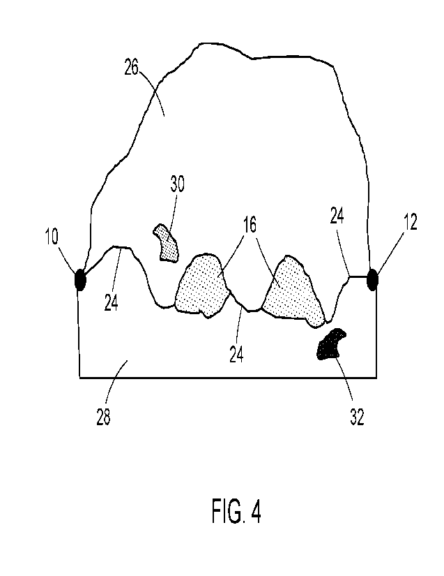
Figure 4 shows a detailed view of a fibre protrusion and its domains. The
interface (24) is defined
as the interface formed between the base film (28) and fibre protrusion (26)
domains, comprising
all the points where the extruded pure fibre element material and the pure
base film material meet
and interact, interrupted by the intermixed domains (16).
The protrusion domain, PD, (26) is the region of protrusion comprising pure
reinforcing fibre
element material (no base film material).
The base film domain, BD (28) is of the region of pure base film material,
which may be found
underneath the PD.
The interface is interrupted by one or more domains (16), which are regions of
intermixed material
of base film material and reinforcing fibre element material and are otherwise
referred to as "ID".
The interface between the PD and BD is partially interrupted by one or more
IDs. The perimeter
of each ID (16) forms two new interfaces, one between the BD and ID and
another between the
PD and ID, which produce interfacial interactions between ID and BD and ID and
PD (leading to
three-part PD-ID-BD interactions).
There may also be regions of intermixed material of base film material and
reinforcing fibre
element material outside of the interface formed between the BD and the PD.
For instance, an
ID may be fully included in the PD (30) and/or BD (32), thus its perimeter may
be fully surrounded
either by PD (26) or BD (28), respectively. These instances of intermixed
domains, being enclosed
23
CA 03184414 2022- 12- 28
WO 2022/018044
PCT/EP2021/070180
wholly by pure reinforcing fibre element material (30) or pure base film
material (32), do not
contribute to interactions at the interface between the pure fibre element
material and the pure
base film material. These regions of intermixed material enclosed wholly in
either base film (32)
or element material (30) may also be referred to as inclusions.
The cross-sectional area is defined by the plane perpendicular to the contact
plane which passes
through C1 (10) and 02 (12) and crosses the base film. It is the area viewable
inside the
reinforcing fibre element if one looks along the length of a fibre protrusion.
Figures 5A-C shows the stress at break, specific energy and strain at break of
the reinforced film
as a function of fibre protrusion maximum height. It is apparent that optimal
properties are
obtained at either extreme of the x-axis on the graph. Some reinforced
thermoplastic films of the
present invention can be viewed as lying on the right-hand side of the x-axis,
i.e., as having
greater fibre protrusion maximum heights, compared to the prior art.
Figure 6A-C shows a similar distribution of stress at break, specific energy,
and strain at break of
the reinforced film but as a function of fibre protrusion maximum width, and
essentially mirrors the
distribution in Figure 5. In this instance, some reinforced thermoplastic
films of the present
invention can be viewed as lying towards the left-hand side of the x-axis,
i.e., have smaller
maximum widths compared to the prior art.
EXAMPLES
zo The following non-limiting Examples demonstrate some reinforced stretch
films of the present
invention. Each specimen of reinforced stretch film may be provided having
thereon one
longitudinal fibre protrusion. Alternatively, a wider reinforced stretch film
with many fibre
protrusions is produced and the specimen is cut out of this film.
The protrusion angles, the maximum height and maximum width of the fibre
protrusion can be
determined by measurement with a suitable microscope.
Example 1
A reinforced fibre film of the present invention is produced by placing a
reinforcing fibre element
of diameter 280 pm on a base film having 500 mm width and thickness 14 pm. The
base film and
the fibre reinforcing elements have the same density, 0.920 g/cm3. The 15 mm
width sample of
24
CA 03184414 2022- 12- 28
WO 2022/018044
PCT/EP2021/070180
said film has one continuous fibre protrusion parallel to the tensile stress
direction and situated
as close as possible to the central portion of the sample width. The weight of
the samples for a
length equal to the grip to grip area (60 mm) is 15 mg. The fibre protrusion
has maximum width,
Wprot.max = 225 pm and maximum height, Hprot.max = 177 pm and the ratio of
Hprot.max over Wprot.max iS
0.79. The protrusion angles PA1 and PA2 are 51 degrees and 60 degrees,
respectively.
Example 2
A reinforced fibre film of the present invention is produced by placing a
reinforcing fibre element
of diameter 311 pm on a base film having 500 mm width and thickness 15pm. The
base film and
the fibre reinforcing elements have the same density, 0.920 g/cm3. The 15 mm
width sample of
said film has one continuous fibre protrusion parallel to the surface of the
film in the machine
direction close as possible to the central portion of the sample width. The
weight of the samples
for a length equal to the grip to grip area (60 mm) is 17 mg. The fibre
protrusion has maximum
width, Wprot.max = 263 pm and maximum height, Hprarnax = 158 pm and the ratio
of Hprot.max over
Wprot.max is 0.60. The protrusion angles PA1 and PA2 are 82 degrees and 80
degrees, respectively.
Example 3
A reinforced fibre film of the present invention is produced by placing a
reinforcing fibre element
of diameter 311 pm on a base film having 500 mm width and thickness 15m. The
base film and
the fibre reinforcing elements have the same density, 0.920 g/cm3. The 15 mm
width sample of
said film has one parallel and continuous fibre protrusion in the machine
direction close as
zo possible to the central portion of the sample width. The weight of the
samples for a length equal
to the grip to grip area is (60 mm) 17 mg. The fibre protrusion has maximum
width, Wprot.max= 329
pm and maximum average height, Hprot.max= 158 pm and the ratio of Hprot.max
over Wprot.max is 0.48.
The protrusion angles PA1 and PA2 are 99 degrees and 108 degrees,
respectively.
Example 4
A reinforced fibre film of the present invention is produced by placing a
reinforcing fibre element
of diameter 286 pm on a base film having 500 mm width and thickness 16pm. The
base film and
the fibre reinforcing elements have the same density, 0.920 g/cm3. The 15 mm
width sample of
said film has one parallel and continuous fibre protrusion in the machine
direction close as
possible to the central portion of the sample width. The weight of the samples
for a length equal
to the grip to grip area is (60 mm) 17 mg. The fibre protrusion has maximum
width, Wprot max= 285
CA 03184414 2022- 12- 28
WO 2022/018044
PCT/EP2021/070180
pm and maximum height, Hprot.max = 156 pm and the ratio of Hprot.max over
Wprot.max is 0.55. The
protrusion angles PA1 and PA2 are 73 degrees and 72 degrees, respectively.
Example 5
A reinforced fibre film of the present invention is produced by placing a
reinforcing fibre element
of diameter 250 pm on a base film having 500 mm width and thickness 14 pm. The
base film and
the fibre reinforcing elements have the same density, 0.920 g/cm3. The 15 mm
width sample of
said film has one parallel and continuous fibre protrusion in the machine
direction close as
possible to the central portion of the sample width. The weight of the sample
for a length equal to
the grip to grip area is (60 mm) 14 mg. The fibre protrusion has maximum
width, Wprotmax = 302
pm and maximum average height, Hprot.max= 119 pm and the ratio of Hprot.max
over W101 max is 0.39.
The protrusion angles PA1 and PA2 are 67 degrees and 107 degrees,
respectively.
Example 6
A reinforced fibre film of the present invention is produced by placing a
reinforcing fibre element
of diameter 259 pm on a base film having 500 mm width and thickness 14 pm. The
base film and
the fibre reinforcing elements have the same density, 0.920 g/cm3. The 15 mm
width sample of
said film has one parallel and continuous fibre protrusion in the machine
direction close as
possible to the central portion of the sample width. The weight of the sample
for a length equal to
the grip to grip area is (60 mm) 15 mg. The fibre protrusion has maximum
width, Wprot.max = 281
pm and maximum height, Hprot.max = 112 pm and the ratio of Hprot.max over
Wprot.max is 0.40. The
zo protrusion angles PA1 and PA2 are 102 degrees and 98 degrees,
respectively.
Example 7
A reinforced fibre film of the present invention is produced by placing a
reinforcing fibre element
of average diameter 291 pm on a base film having 500 mm width and thickness 15
pm. The base
film and the fibre reinforcing elements have the same density, 0.920 g/cm3.
The 15 mm width
sample of said film has one parallel and continuous fibre protrusion in the
machine direction close
as possible to the central portion of the sample width. The weight of the
sample for a length equal
to the grip to grip area is (60 mm) 16 mg. The fibre protrusion has maximum
width, Wprot.max = 483
pm and maximum height, Hprot.max = 101 pm and the ratio of Hprot.max over
Wprot.max is 0.21. The
protrusion angles PA1 and PA2 are 149 degrees and 142 degrees, respectively.
The above inventive reinforced stretch film examples of the present invention
are compared in
Table 1.
26
CA 03184414 2022- 12- 28
WO 2022/018044
PCT/EP2021/070180
Table 1 ¨ Parameters of the Examples and their physical and mechanical
properties
Reinforcing
Sample Stress
Fibre Strain
at Specific
H Protr max WProtr max PA1 PA2 weight at
Element break
Energy
(pm) (pm) ( ) ( ) x10-3 break
Example diameter (c/o)
(J/g)
(g) (MPa)
No. (pm)
1 280 177 225 51 60 15 9.8 271 28.0
2 311 159 263 82 80 17 9.6 74
8.2
3 311 158 329 99 108 17 6.6 52
5.3
4 286 156 285 73 72 17 9.4 71
7.6
250 119 302 67 107 14 9.1 69 7.1
6 259 112 281 102 98 15 8.9 58
6.0
7 291 101 483 149 142 16 14.6 319
50.6
5
Data Analysis
The data produced indicate that the relative dimensions (in particular the
maximum height of fibre
protrusion) have a role in shaping the resulting properties of the reinforced
thermoplastic film.
Increasing the maximum height of the fibre protrusion increases the barrier
against tearing, while
at the same time the existence of one or more discrete intermixed domains
underneath the fibre
protrusion provide a structured support inhibiting tear propagation.
On the other hand, when decreasing the maximum height of the fibre protrusion
and thereby also
increasing the area occupied by intermixed domains underneath the fibre
protrusion and along
the interface formed between the base film domain and the fibre protrusion
domain, a critical
27
CA 03184414 2022- 12- 28
WO 2022/018044
PCT/EP2021/070180
maximum height is reached beyond which the physical and mechanical properties
(e.g., energy
to break, elongation and strength) improve again.
28
CA 03184414 2022- 12- 28