Note: Descriptions are shown in the official language in which they were submitted.
WO 2022/008593
PCT/EP2021/068830
SAFETY MECHANISM FOR CHILD CAR SEAT
BACKGROUND OF THE INVENTION
Field of the Invention
pool] The present invention relates to the field of child car seats, and more
particularly,
to a child car seat safety mechanism.
Description of the Related Art
[own] A child car seat is a seat designed exclusively for a child. The child
car seat is
assembled in a vehicle for a child to be seated on the child car seat, so as
to restrain a
child by the child car seat and ensure safety of the child.
[0003] A child car seat usually includes a seat portion, a turntable and a
base. The seat
portion is disposed on the turntable, and the turntable can drive the seat
portion to
rotate relative to the base so that the seat portion can be rotated to front-
face or back-
face the head of the vehicle. When the seat portion is rotated relative to the
base to
front-face the head of the vehicle, the seat portion is in a forward mode;
when the seat
portion is rotated relative to the base to back-face the head of the vehicle,
the seat
portion is in a backward mode; when the seat portion is rotated by 90 degrees
from the
forward mode or the backward mode, the seat portion is in a sideward mode. Due
to
age issues and safety issues, infants under one-year -old can only use a child
car seat
having a hand-carry basket as the seat portion. The hand-carry basket of the
child car
seat can be used when rotated to the backward mode or the sideward mode, but
cannot
be used when rotated to the forward mode; only children from one to twelve
years old
can use the child car seat having a seat as the seat portion, and the seat of
the child car
seat can be used when rotated to the forward mode, the backward mode and the
1
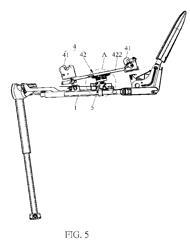
CA 03185090 2023- 1- 5
WO 2022/008593
PCT/EP2021/068830
sideward mode. However, current child car seats face the following technical
issues.
As the age of a child increases, different seat portions are required for the
child car
seat, and the cost becomes higher if child car seats with different seat
portions are
purchased separately at different ages of a child. Moreover, assuming that the
seat
portion and the turntable are detachable from each other and a seat portion is
to be
replaced by another seat portion, when the seat in the forward mode is removed
from
the turntable and replaced by a hand-carry basket, the hand-carry basket at
this point is
in the forward mode. As a result, parents or a user may mistake that the hand-
carry
basket can also be used in the forward mode, causing tremendous safety issues.
SUMMARY OF THE INVENTION
[0004] It is an object of the present invention to provide a safety mechanism
for a child
car seat supporting replacement of different seat portions.
[0005] To achieve the object above, the present invention provides a safety
mechanism
for a child car seat including a base, a turntable and a seat portion. The
safety
mechanism further includes a locking mechanism and a releasing mechanism. The
turntable is pivotally connected to an upper part of the base. The locking
mechanism is
disposed at the turntable, and the locking mechanism is connected to the seat
portion
and locks the seat portion at the turntable. The releasing mechanism is
disposed at the
base, and the releasing mechanism is operable to drive the locking mechanism
to
release the seat portion.
[0006] Preferably, the child car seat safety mechanism further includes a
cutoff member.
The cutoff member is disposed between the locking mechanism and the releasing
mechanism, and the turntable is rotated by a certain angle relative to the
seat, so that
the cutoff member can cutoff or allow the linkage between the releasing
mechanism and
the locking mechanism.
[0007] Preferably, the locking mechanism includes a locking member, the
releasing
mechanism includes a releasing member, and the releasing member drives the
locking
member to operate so as to release the seat portion.
2
CA 03185090 2023- 1- 5
WO 2022/008593
PCT/EP2021/068830
[0008] Preferably, the locking mechanism includes a rotary trajectory of
rotation relative
to the base, and the releasing mechanism faces the rotary trajectory.
[0009] Preferably, the rotary trajectory is dotted.
o] Preferably, a limiting protrusion is provided on a side of the releasing
member,
the cutoff member is disposed at the turntable, and the turntable is rotated
by a certain
angle relative to the base, so that the cutoff member blocks the limiting
protrusion or the
cutoff member is misaligned with the limiting protrusion.
[own] Preferably, the releasing mechanism includes a first driving member. The
first
driving member is slidably disposed at the base, the first driving member is
provided
with a first driving chute, the releasing member is slidably disposed at the
first driving
chute, and the releasing member is driven by sliding the first driving member
to move
and drive the locking member to operate.
[0012] Preferably, the releasing mechanism further includes a first releasing
manipulation member and a first pull string. The first releasing manipulation
member is
pivotally connected to the base, the first pull string is connected between
the first
releasing manipulation member and the fist driving member, and the first
releasing
manipulation member is rotated to pull the first pull string and drive the
first driving
member to slide.
[0013] Preferably, the releasing mechanism further includes a first elastic
reset member
for resetting the first driving member, and the first elastic reset member is
disposed
between the first driving member and the base.
[0014] Preferably, the locking mechanism includes a linkage assembly. The
linkage
assembly is disposed at the turntable and is located above the releasing
member, and
the releasing member is operated to drive the linkage assembly, so that the
linkage
assembly drives the locking member and releases the seat portion.
[0015] Preferably, the linkage assembly includes a first push member and a
pull
member. The first push member is disposed in an up-and-down manner at the
3
CA 03185090 2023- 1- 5
WO 2022/008593
PCT/EP2021/068830
turntable, the first push member is provided with a first inclined plane, the
pull member
is horizontally movably disposed at the turntable, the pull member is provided
with a
second inclined plane, the first inclined plane is abutted against the second
inclined
plane, and the first push member is pushed upward by the releasing member, so
that
the first push member drives the pull member to move and the pull member
drives the
locking member to release the seat portion.
[0016] Preferably, the linking assembly further includes a second elastic
reset member
for resetting the first push member, and the second elastic resetting member
is
disposed between the first push member and the pull member.
[0017] Preferably, a blocking member and a block mechanism are further
included. The
blocking member is fixed at the base, the blocking mechanism is movably
disposed at
the turntable, and one end of the blocking mechanism is moved and extended out
of the
turntable or hidden in the turntable, so that the blocking mechanism blocks or
is evaded
from the blocking member.
N018] Preferably, the blocking mechanism includes a second driving member and
a
stop block. The second driving member is slidably disposed in the turntable,
the stop
block is fixedly connected to the second driving member, the stop block is
disposed in a
penetrating manner at the turntable, the blocking member is fixed at the base,
and the
stop block is driven by sliding the second driving member, so that the stop
block is
extended out of the turntable or is hidden in the turntable, and the stop
block blocks or
is evaded from the blocking member.
[0019] Preferably, the blocking mechanism further includes a second push
member, the
second driving member is provided with a second driving chute, the second push
member is slidably disposed at the second driving chute, the seat portion is
provided
with a driving assembly, and the second push member is driven by the driving
assembly
to drive the second driving member to slide.
[0020] Preferably, the driving assembly includes a second releasing
manipulation
member, a transmission assembly and a driving pin. The second releasing
4
CA 03185090 2023- 1- 5
WO 2022/008593
PCT/EP2021/068830
manipulation member is movably disposed on the seat portion, the driving pin
is up-and-
down movably disposed at the seat portion and is located above the second push
member, the transmission assembly is connected between the second releasing
manipulation member and the driving pin, and the second releasing manipulation
member is driven to drive the transmission assembly, so as to drive the
driving pin to
move downward and push the second push member.
[0021] Preferably, the transmission assembly includes a rotating member. The
rotating
member is pivotally connected in the seat portion, one end of the rotating
member is
connected to the second releasing manipulation member, the other end of the
rotating
member is connected to the driving pin, and the rotating member is driven by
the
second releasing manipulation member to rotate so as to drive the driving pin
to move.
[0022] Preferably, the second releasing manipulation member is slidably
disposed on
the seat portion, the second releasing manipulation member is in contact
connection
with the rotating member, and the rotating member is pushed by sliding the
second
releasing manipulation member to rotate.
[0023] Preferably, the second releasing manipulation member is provided with a
driving
inclined plane for driving the rotating member to rotate.
[0024] Preferably, the seat portion includes a beam fixed therein, and the
rotating
member is pivotally connected to the beam.
[0025] Preferably, the driving assembly further includes a fifth elastic reset
member for
resetting the driving pin, and the fifth elastic reset member is disposed
between the
driving pin and the seat portion.
[0026] Preferably, the second releasing manipulation member is pivotally
connected to
the seat portion.
[0027] Preferably, a propelling member is further included. The propelling
member is
slidably disposed on an upper surface of the turntable and is located between
the
second push member and the driving assembly. The propelling member includes a
CA 03185090 2023- 1- 5
WO 2022/008593
PCT/EP2021/068830
body and a through hole provided at the body, the driving assembly passes
through the
through hole to drive the second push member, and the propelling member is
driven to
slide so that the body blocks the driving assembly.
[0028] Preferably, the body is provided with a protrusion, the turntable is
provided with a
sliding groove, and the protrusion is slidably disposed at the sliding groove.
[0029] Preferably, a resilient assembly is further included. The turntable is
provided with
a groove opening in communication with the sliding groove, the resilient
assembly is
disposed at the groove opening and is located between the push member and the
turntable, and the propelling member is driven to slide, so that the
propelling member
presses or releases the resilient assembly.
[0030] Preferably, the resilient assembly includes a top block and a third
elastic reset
member. The top block is slidably disposed at the groove opening, one end of
the top
block protrudes to the sliding groove, and the sliding direction of the top
block is
opposite to the sliding direction of the propelling member. The third elastic
reset
member is disposed between the top block and the turntable.
[0031] Preferably, the end portion of the top block protruding to the sliding
groove is of
an arc-shaped structure.
[0032] Preferably, the second push member includes a first push portion and a
second
push portion. The first push portion is disposed above the second push
portion, the first
push portion is fitted in the through hole, and the second push portion is
slidably
disposed at the second driving chute.
[0033] Preferably, the blocking mechanism further includes a fourth elastic
reset
member for resetting the second driving member, and the fourth elastic reset
member is
disposed between the turntable and the second driving member.
[0034] Preferably, plural blocking members are fixed at intervals at the base
along a
rotation direction of the turntable.
6
CA 03185090 2023- 1- 5
WO 2022/008593
PCT/EP2021/068830
[0035] Preferably, the seat portion has a forward mode of facing forward and a
backward mode of facing backward relative to the base, and the turntable
drives the
seat portion to rotate from the backward mode to the forward mode, so that the
cutoff
member cuts off the linkage between the releasing mechanism and the locking
mechanism.
[0036] Preferably, the seat portion is detachably connected to an upper part
of the
turntable.
[0037] Preferably, when the seat portion is connected to the turntable, the
seat portion is
in the backward mode.
[0038] Preferably, an upper surface of the turntable is provided with a first
fitting position
and a second fitting position arranged at an interval, the seat portion is
provided with a
first fitting portion and a second fitting portion, the first fitting portion
is fitted at the first
fitting position, and the second fitting portion is fitted at the second
fitting position.
[0039] Preferably, the seat portion is a hand-carry basket or a seat for a
child car seat.
[0040] Compared to the prior art, the safety mechanism for the child car seat
of the
present invention includes a locking mechanism on a turntable, a releasing
mechanism
on a base, and a blocking member between the locking mechanism and the
releasing
mechanism. The seat portion is locked at the turntable by the locking member,
and the
releasing member is operable to drive the locking member to release the seat
portion,
so that the seat portion can be removed and be replaced by a different seat
portion.
Thus, a consumer does not need to further purchase a child car seat having a
different
seat portion, thereby reducing utilization costs for the consumer.
BRIEF DESCRIPTION OF THE DRAWINGS
[0041] FIG. 1 is a structural schematic diagram of a hand-carry basket in a
backward mode of a child car seat safety mechanism of the present invention;
FIG. 2 is a structural schematic diagram of a seat in a backward mode of a
child car seat safety mechanism of the present invention;
7
CA 03185090 2023- 1- 5
WO 2022/008593
PCT/EP2021/068830
FIG. 3 is a structural schematic diagram of a seat in a forward mode of a
child car seat safety mechanism of the present invention;
FIG. 4 is a structural schematic diagram of a turntable and a base of a
child car seat safety mechanism according to a first embodiment of the present
invention;
FIG. 5 is a structural schematic diagram of a child car seat safety
mechanism in FIG. 4 excluding a partial housing of the turntable and a partial
housing of
the base;
FIG. 6 is an enlarged view of part A in FIG. 5;
FIG. 7 is a structural schematic diagram of a releasing mechanism of a
child car seat safety mechanism of the present invention;
FIG. 8 is a structural schematic diagram of a releasing member of a child
car seat safety mechanism of the present invention;
FIG. 9 is a diagram of an internal structural of a turntable and a base of a
child car seat safety mechanism of the present invention;
FIG. 10 is an enlarged view of part B in FIG. 9;
FIG. 11 is a schematic diagram of a releasing member facing a rotary
trajectory of a locking member in a child car seat safety mechanism according
to a first
embodiment of the present invention;
FIG. 12 is a schematic diagram of a releasing member facing a rotary
trajectory of a locking member in a child car seat safety mechanism according
to a
second embodiment of the present invention;
FIG. 13 is a diagram of an internal structural of a turntable and a base of a
child car seat safety mechanism of the present invention from another angle;
FIG. 14 is an enlarged view of part C in FIG. 13;
8
CA 03185090 2023- 1- 5
WO 2022/008593
PCT/EP2021/068830
FIG. 15 is an enlarged view of part D in FIG. 13;
FIG. 16 is a structural schematic diagram of a seat portion of a child car
seat safety mechanism of the present invention;
FIG. 17 is a structural schematic diagram of a seat portion of a child car
seat safety mechanism according to another embodiment of the present
invention;
FIG. 18 is a structural schematic diagram of a driving assembly of a child
car seat safety mechanism of the present invention;
FIG. 19 is a structural schematic diagram of a turntable and a base of a
child car seat safety mechanism according to the second embodiment of the
present
invention; and
FIG. 20 is a structural schematic diagram of a propelling member removed
from a turntable of a child car seat safety mechanism of the present
invention.
DETAILED DESCRIPTION
[0042] To better describe the technical contents and structural features of
the present
invention, embodiments are given in detail with the accompanying drawings
below.
[0043] Referring to FIG. 1 to FIG. 5, a child car seat safety mechanism 100 of
the
present invention includes a base 1, a turntable 2, a seat portion 3, a
locking
mechanism 4, a releasing mechanism 5 and a cutoff member 21. The turntable 2
is
pivotally connected to an upper part of the base 1. The locking member 4 is
disposed
at the turntable 2 and is connected to the seat portion 3 and locks the seat
portion 3 at
the turntable 2. The releasing mechanism 5 is disposed at the base 1 and is
operable
to drive the locking mechanism 4 to release the seat portion 3. More
specifically, the
locking mechanism 4 includes a locking member 41, the releasing mechanism 5
includes a releasing member 51, and the releasing member 51 can drive the
locking
member 41 to operate to release the seat portion 3. The cutoff member 21 is
disposed
between the locking mechanism 4 and the releasing mechanism 5, and the
turntable 2
is rotated by a certain angle relative to the base 1, so that the cutoff
member 21 blocks
9
CA 03185090 2023- 1- 5
WO 2022/008593
PCT/EP2021/068830
or allows linkage between the releasing mechanism 5 and the locking mechanism
4. In
this embodiment, the seat portion 3 has a forward mode of facing forward and a
backward mode of facing backward relative to the base 1, and the turntable 2
drives the
seat portion 3 to rotate from the backward mode to the forward mode, so that
the cutoff
member 21 blocks the linkage between the releasing mechanism 5 and the locking
mechanism 4. According to the invention, the seat portion 3 is a hand-carry
basket or a
seat for the child car seat. As shown in FIG. 3, when the turntable 2 drives
the seat
portion 3 to rotate by a certain angle relative to the base 1, the seat
portion 3 is in the
forward mode, and the cutoff member 21 blocks the linkage between the
releasing
mechanism 5 and the locking mechanism 4, so that the releasing mechanism 5 is
incapable of driving the locking mechanism 4 for releasing the seat portion 3,
and thus
the seat portion 3 in the forward mode cannot be removed. As shown in FIG. 2,
when
the turntable 2 drives the seat portion 3 to rotate by a certain angle
relative to the base
1, the seat portion 3 is in the backward mode or a sideward mode, and the
cutoff
member 21 no longer blocks the linkage between the releasing mechanism 5 and
the
locking member 4, so that the releasing mechanism 5 is capable of driving the
locking
mechanism 4 to release the seat portion 3. Thus, the seat portion 3 in the
backward
mode or the sideward mode can be removed, and replacement by a different seat
portion 3 can be carried out, for example, replacing the seat in FIG. 2 acting
as the seat
portion 3 to the hand-carry basket in FIG. 1 acting as the seat portion 3.
[0044] Referring to FIG. 6 and FIG. 7, in this embodiment, the releasing
mechanism 5
includes a first driving member 52, a first releasing manipulation member (not
shown)
and a first pull string 53. The first driving member 52 is slidably disposed
at the base 1,
the first driving member 52 is provided with a first driving chute 521, the
releasing
member 51 is slidably disposed at the first driving chute 521, the first
releasing
manipulation member is pivotally connected at the base 1, the first pull
string 53 is
connected between the first releasing manipulation member and the first
driving
member 52, and the first releasing manipulation member is rotated to pull the
first pull
string 53 and drive the first driving member 52 to slide, so that the first
driving member
52 drives via the first driving chute 521 the releasing member 51 to move, and
that the
releasing member 51 drives the locking member 41 to operate. Further, the
releasing
CA 03185090 2023- 1- 5
WO 2022/008593
PCT/EP2021/068830
mechanism 5 further includes a first elastic reset member 54 for resetting the
first
driving member 52, and the first elastic reset member 54 is disposed between
the first
driving member 52 and the base 1. When the first releasing manipulation member
is
rotated, the first pull string 53 pulls the first driving member 52 to move
horizontally, and
the first driving member 52 compresses the first elastic reset member 54. When
the
first releasing manipulation member is released, the first driving member 52
is reset
under the effect of the elastic restoring force of the first elastic reset
member 54.
However, the structure of the releasing mechanism 5 is not limited to the
example
above. In other embodiments, for example, the releasing mechanism 5 may be
provided with only a driving block. The driving block may be up-and-down
slidably
disposed on the base 1, and the driving block is directly operated to slide
upward, so
that the driving block directly drives the releasing member 51 to slide and
move upward
and to drive the locking member 41 to operate. For another example, the
releasing
mechanism 5 may be provided with only the first driving member 52, and the
releasing
member 51 is driven via the first driving chute 521 of the first driving
member 52 to
move up and down.
[0045] Referring to FIG. 5 and FIG. 6, in this embodiment, the locking
mechanism 4
includes a linkage assembly 42. The linkage assembly 42 is disposed at the
turntable 2
and is located above the releasing member 41, and specifically, the linkage
assembly
42 is located between the releasing member 51 and the locking member 41. The
releasing member 51 is operated to drive the linkage assembly 42, so that the
linkage
assembly 42 drives the locking member 41 and releases the seat portion 3. More
specifically, the linkage assembly 42 includes a first push member 421 and a
pull
member 422. The first push member 421 may be disposed in an up-and-down manner
at the turntable 2 and be located above the releasing member 51, and the first
push
member 421 is provided with a first inclined plane 421a. The pull member 422
is
horizontally movably disposed at the turntable 2, and the pull member 422 is
provided
with a second inclined plane 422a, wherein the first inclined plane 421a is
abutted
against the second inclined plane 422a. By pushing the first push member 421
upward
by the releasing member 51 and with the coordination of the first inclined
plane 421a
and the second inclined plane 422a, the first push member 421 drives the pull
member
11
CA 03185090 2023- 1- 5
WO 2022/008593
PCT/EP2021/068830
422 to move, so that the pull member 422 drives the locking member 41 to open
and
release the seat portion 3. Further, the linking assembly 42 further includes
a second
elastic reset member 423 for resetting the first push member 421, and the
second
elastic resetting member 423 is disposed between the first push member 421 and
the
pull member 422. When the releasing member 51 pushes the first push member 421
upward, the first push member 421 presses the second elastic reset member 423;
when
the releasing member 51 no longer pushes the first push member 421, the first
push
member 421 may be reset under the effect of the second elastic reset member
423, and
the pull member 422 at the same time is reset along with the reset of the
first push
member 421. To further enhance the reset capability of the pull member 422, an
elastic
reset member for resetting the pull member 422 may also be disposed between
the pull
member 422 and the turntable 2. It should be noted that, the structure of the
locking
mechanism 4 is not limited to the example above. In other embodiments, for
example,
the linkage assembly 42 may be omitted from the locking member 4, and the
locking
member 41 is directly driven by the releasing member 51 to release. For
another
example, the locking mechanism 4 may be provided with only the locking member
41
and a swinging member, wherein one end of the swinging member is pivotally
connected to the turntable 2, and the swinging member is pushed by the
releasing
member 51 of the releasing mechanism 5 to swing, so that the swinging member
pushes the locking member 41 to operate and release the seat portion 3.
[0046] Referring to FIG. 8 to FIG. 10, in this embodiment, a limiting
protrusion 511 is
provided on a side of the releasing member 51. The blocking member 51 is
disposed at
the turntable 2, and the turntable 2 is rotated by a certain angle relative to
the base 1,
so that the cutoff member 21 blocks the limiting protrusion 511 or the cutoff
member 21
is misaligned with the limiting protrusion 511. More specifically, the bottom
of the
turntable 2 is provided with a through hole 27 at a position corresponding to
the
releasing member 51. The cutoff member 21 is fixed at an inner wall of the
through
hole 27, and the releasing member 51 may be extended into the through hole 27
and
push the first push member 421 of the linkage assembly 42. Once the turntable
2 is
rotated by a certain angle relative to the base 1, the cutoff member 21 is
located above
the limiting protrusion 511 of the releasing member 41, and the releasing
member 51 is
12
CA 03185090 2023- 1- 5
WO 2022/008593
PCT/EP2021/068830
incapable of moving upward due to the blocking effect of the blocking member
41, such
that the releasing member 51 is incapable of pushing the first pushing member
421 of
the linkage assembly 42 upward. Thus, the linkage between the releasing
mechanism
and the locking mechanism 4 is blocked, the releasing mechanism 5 is incapable
of
driving the locking mechanism 4 for releasing the seat portion 3, and the seat
portion 3
in the forward mode cannot be removed as a result. When the turntable 2
continues
rotating by a certain angle relative to the base 1, the cutoff member 21 is
misaligned
with the limiting protrusion 511, and the cutoff member 21 no longer blocks
the upward
movement of the releasing member 51, so that the releasing member 51 becomes
capable of pushing the first push member 421 of the linkage assembly 42,
further
allowing the linkage between the releasing mechanism 5 and the locking
mechanism 4
and having the locking member 41 release the seat portion 3.
[0047] Referring to FIG.11, in this embodiment, the locking mechanism 4 and
the
releasing mechanism 5 are individually located on a rotation axis of rotation
relative to
the base 1. The locking mechanism 4 has a rotary trajectory of rotation
relative to the
base 1, and the releasing mechanism 5 faces the rotary trajectory. In the
drawing, L
represents the rotary trajectory of rotation relative to the base 1, and the
rotary
trajectory is dotted. Relative positions of the locking mechanism 4 and the
releasing
mechanism 5 are constant; that is, along with the rotation of the turntable 2
relative to
the base 1, the releasing mechanism 5 and the locking mechanism 4 keep facing
each
other, and more specifically, the releasing member 51 of the releasing
mechanism 5
keeps facing the first push member 421 of the locking mechanism 4. Thus, the
turntable 2 can be driven to rotate relative to the base 1, so that the cutoff
member 21
blocks the limiting protrusion 511 of the releasing member 51 or the cutoff
member 21 is
misaligned with the limiting protrusion 511 of the releasing member 51. In
other
embodiments, as shown in FIG. 12, the locking mechanism 4 and the releasing
mechanism 5 are individually disposed in a direction deviated from the
rotation axis of
rotation of the turntable 2 relative to base 1, and L in the drawing
represents a rotary
trajectory of rotation of the base 1. The cutoff member 21 is disposed on the
turntable
2, and the cutoff member 21 and the turntable 2 may be an integral structure;
that is, the
cutoff member 21 is a part of the turntable 2. Once the locking mechanism 4 is
rotated
13
CA 03185090 2023- 1- 5
WO 2022/008593
PCT/EP2021/068830
to a certain angle, the locking mechanism 4 and the releasing mechanism 5 then
become facing each other. At this point, the cutoff member 21 allows the
linkage
between the releasing mechanism 5 and the locking mechanism 4; that is, the
cutoff
member 21 no longer blocks the linkage between the releasing mechanism 5 and
the
locking mechanism 4. When the locking mechanism 4 continues rotating to a
certain
angle, the releasing mechanism 5 and the locking mechanism 4 are misaligned
with
each other, and the cutoff member 21 on the turntable 2 then blocks the
linkage
between the releasing mechanism 5 and the locking mechanism 4.
[0048] Referring to FIG. 13 to FIG. 15, in this embodiment, the child car seat
safety
mechanism 100 of the present invention further includes a blocking member 11
and a
block mechanism 22. The blocking member 11 is fixed at the base 1, the
blocking
mechanism 22 is movably disposed at the turntable 2, and one end of the
blocking
mechanism 22 is moved and protruding out of the turntable 2 or is hidden in
the
turntable 2, so that the blocking member 22 blocks or is evaded from the
blocking
member 11. More specifically, two blocking members 11 are fixed at an interval
at the
base 1 in a rotation direction of the turntable 2 , and the turntable 2 can
drive the
blocking mechanism 22 to rotate together. When one end of the blocking
mechanism
22 is extended out of the turntable 2, blocking between the blocking mechanism
22 and
the blocking member 11 occurs, so that the turntable 2 is blocked from keep
rotating
and the rotation angle of the turntable 2 relative to the base 1 is limited.
Thus, the
turntable 2 cannot achieve 360-degree rotation, and the seat portion 3
disposed on the
turntable 2 likewise cannot rotate by 360 degrees, such that the seat portion
3 is
capable of rotating only to a certain angle on the two sides, that is,
rotating to the
sideward mode. When one end of the blocking mechanism 22 is hidden in the
turntable
2, the blocking mechanism 22 can be evaded from the blocking member 11, so
that the
turntable 2 achieves 360-degree rotation, and the seat portion 3 disposed on
the
turntable 2 likewise achieves 360-degree rotation. The number of blocking
member 11
is not limited to the example above, and the number of blocking member 11 may
be one
or three. More specifically, the blocking mechanism 22 includes a second
driving
member 221 and a stop block 222. The second driving member 221 is slidably
disposed in the turntable 2, the stop block 222 is fixedly connected to the
second driving
14
CA 03185090 2023- 1- 5
WO 2022/008593
PCT/EP2021/068830
member 221, the stop block 222 is disposed in a penetrated manner at the
turntable 2,
the blocking member 11 is fixed at the base1, and the stop block 222 is
extended out of
the turntable 2 or is hidden in the turntable 2 by sliding the second driving
member 221
to drive the stop block 222, so that the stop block 222 blocks or is evaded
from the
blocking member 11. When blocking between the stop block 222 and the blocking
member 11 occurs, the turntable 2 is blocked from keep rotating, so that the
rotation
angle of the turntable 2 relative to the base 1 is limited; when the stop
block 222 is
evaded from the blocking member 11, the turntable 2 can achieve 360-degree
rotation.
Further, the releasing mechanism 22 further includes a fourth elastic reset
member 224
for resetting the second driving member 221, and the fourth elastic reset
member 224 is
disposed between the turntable 2 and the second driving member 221. When the
second driving member 221 slides and drives the stop block 222 to be hidden in
the
turntable 2, the second driving member 221 presses the fourth elastic reset
member
224; when the second driving member 221 is released, the second driving member
221
may be reset under the effect of the elastic restoring force of the fourth
elastic reset
member 224, so that the second driving member 221 drives the stop block 222 to
extend out of the turntable 2.
[0049] Referring to FIG. 14 to FIG. 16, in order to enable the turntable 2 to
rotate by 360
degrees only when the seat portion 3 is mounted on the turntable 2, the
blocking
mechanism 22 further includes a second push member 223, the second driving
member
221 is provided with a second driving chute 221a, the second push member 223
is
slidably disposed at the second driving chute 221a, the seat portion 3 is
provided with a
driving assembly 31, and the second push member 223 is driven by the driving
assembly 31 to drive the second driving member 221 to slide. More
specifically, the
driving assembly 31 includes a second releasing manipulation member 311, a
transmission assembly and a driving pin 312. The second releasing manipulation
member 311 is movably disposed on the seat portion 3, the driving pin 312 is
up-and-
down movably disposed at the seat portion 3 and is located above the second
push
member 223, and the transmission assembly is connected between the second
releasing manipulation member 311 and the driving pin 312. The second
releasing
manipulation member 311 is driven to drive the transmission assembly, so that
the
CA 03185090 2023- 1- 5
WO 2022/008593
PCT/EP2021/068830
driving assembly 31 drives the driving pin 312 move downward and push the
second
push member 223. Under the effect of the second driving chute 221a, the second
push
member 223 can drive the second driving member 221 to move horizontally, so
that the
second driving member 221 drives the stop block 222 to hide in the turntable 2
and the
stop block 222 to be evaded from the blocking member 11. Thus, the turntable 2
can
achieve 360-degree rotation relative to the base 1, and the seat portion 3
disposed on
the turntable 2 can similarly achieve 360-degree rotation. As shown in FIG.
16, in one
embodiment, the second releasing manipulation member 311 is pivotally
connected to
the seat portion 3, the transmission assembly can adopt a pull string (not
shown) and a
driving member (not shown) provided with a chute as described above to drive
the
driving pin 312 to move up and down, and the driving pin 312 is inserted in
the chute.
The second releasing manipulation member 311 is rotated to pull the pull
string, so that
the pull string pulls the driving member to slide and the driving pin 312 is
driven via the
chute to move. As shown in FIG. 17 and FIG. 18, in another embodiment, the
transmission assembly includes a rotating member 313. The rotating member 313
is
pivotally connected in the seat portion3, one end of the rotating member 313
is
connected to the second releasing manipulation member 311, and the other end
of the
rotating member 313 is connected to the driving pin 312. The rotating member
313 is
driven by the second releasing manipulation member 311 to rotate, so as to
drive the
driving pin 312 to move. More specifically, the second releasing manipulation
member
311 is slidably disposed on the seat portion 3, the second releasing
manipulation
member 311 is in contact connection with the rotating member 313, the seat
portion 3
includes therein a fixed beam 34, the rotating member 313 is pivotally
connected to the
beam 34, and the rotating member 313 is pushed by sliding the second releasing
manipulation member 311 to slide. The second releasing manipulation member 311
is
provided with, for example but not limited to, a driving inclined plane 311a
for driving
and rotating the rotating member 313. Moreover, the driving assembly further
includes
a fifth elastic reset member 314 for resetting the driving pin 312, and the
fifth elastic
reset member 314 is disposed between the driving pin 312 and the seat portion
3. By
driving the second releasing manipulation member 311 to slide, the second
releasing
manipulation member 311 drives the rotating member 313 via the driving
inclined plane
16
CA 03185090 2023- 1- 5
WO 2022/008593
PCT/EP2021/068830
311a to rotate, so that the rotating member 313 drives the driving pin 312 to
move
downward to push the second push member 223, and at the same time to press the
fifth
elastic reset member 314. When the second releasing manipulation member 311 is
released, the driving pin 312 may be rotated and reset under the elastic force
of the fifth
elastic reset member 314, and the rotating member 313 and the second releasing
manipulation member 311 are driven and reset. The fifth elastic reset member
314 is,
for example but not limited to, a torsion spring.
[0050] Referring to FIG. 19 and FIG. 20, a hand-carry basket serving as the
seat portion
3 can only be used in the backward mode or the sideward mode, but cannot be
rotated
to the forward mode and be used accordingly, and only a seat serving as the
seat
portion 3 can be adjusted and rotated to the forward mode and be used
accordingly. To
enhance the safety of a child car seat, the child car seat safety mechanism
100 of the
present invention further includes a propelling member 6. The propelling
member 6 is
slidably disposed on an upper surface of the turntable 2 and is located
between the
second push member 223 and the driving assembly 31. The propelling member 6
includes a body 61 and a through hole 62 provided at the body 61, the driving
assembly
31 passes through the through hole 62 to drive the second push member 223, and
the
propelling member 6 is driven to slide so that the body 61 blocks the driving
assembly
31. More specifically, the body 61 is provided with a protrusion 611, the
turntable 2
includes a fixed fixing member 23, the fixing member 23 is provided with a
sliding
groove 231, and the protrusion 611 is slidably disposed at the sliding groove
231. The
fixing member 23 and the turntable 2 may be, for example but not limited to,
an integral
structure. When the hand-carry basket acts as the seat portion 3, in order to
refrain the
hand-carry basket from 360-degree rotation and prevent the hand-carry basket
from
rotating to the forward mode, the propelling member 6 is operated to slide, so
that the
propelling member 6 blocks the driving assembly 31 from driving the second
push
member 223 downward and the stop block 222 is kept as extended out of the
turntable
2. Thus, the turntable 2 is incapable of rotating 360 degrees, that is, the
hand-carry
basket is refrained from 360-degree rotation. When the seat acts as the seat
portion 3,
the propelling member 6 is operated to slide, so that the driving assembly 31
is allowed
to pass through the through hole 62 to drive the second push member 223, the
second
17
CA 03185090 2023- 1- 5
WO 2022/008593
PCT/EP2021/068830
push member 223 drives the second driving member 221 to move horizontally, and
the
second driving member 221 moving horizontally drives the stop block 222 to
hide in the
turntable 2. Thus, the stop block 222 can be evaded from the blocking member
11,
allowing the turntable 2 to achieve 360-degree rotation relative to the base
1; that is, the
seat can also achieve 360-degree rotation, and can be rotated and adjusted to
the
forward mode. In enhance the feel of operating the propelling member 6 for a
user, the
child car seat safety mechanism 100 of the present invention further includes
a resilient
assembly 24. The turntable 2 is provided with a groove opening in
communication with
the sliding groove 231, the resilient assembly 24 is disposed at the groove
opening and
is located between the propelling member 6 and the turntable 2, and the
propelling
member 6 is driven to slide, so that the propelling member 6 presses or
releases the
resilient assembly 24. More specifically, the resilient assembly 24 includes a
top block
241 and a third elastic reset member 242. The top block 241 is slidably
disposed at the
groove opening, one end of the top block 241 protrudes to the sliding groove
231, and
the sliding direction of the top block 241 is opposite to the sliding
direction of the
propelling member 6. The third elastic reset member 242 is disposed between
the top
block 241 and the turntable 2. During the operation and sliding process of the
propelling member 6, the protrusion 611 of the propelling member 6 first
pushes the top
block 241 to be withdrawn into the groove opening, such that the top block 241
presses
the third elastic reset member 242. Then, the protrusion 611 crosses over the
top block
241, and the top block 241 may be reset under the effect of the elastic
restoring force of
the third elastic reset member 242. Further, an end portion of the top block
241
protruding to the sliding groove 231 appears as an arc-shaped structure,
accordingly
enhancing the ease for operation for sliding the propelling member 6.
[0051] Referring to FIG. 14, FIG. 19 and FIG. 20, in the child car seat safety
mechanism
100 according to another embodiment of the present invention, the second push
member 223 includes a first push portion 223a and a second push portion 223b.
The
first push portion 223a is disposed above the second push portion 223b, the
first push
portion 223a is fitted in the through hole 62, the second push portion 223b is
slidably
disposed at the second driving chute 221a, and the other structures remain the
same.
By operating the propelling member 6 to slide, the propelling member 6 drives
the first
18
CA 03185090 2023- 1- 5
WO 2022/008593
PCT/EP2021/068830
push portion 223a to move, so that the first push portion 223a and the second
push
portion 223b are misaligned with each other; the body 61 of the propelling
member 6 is
located between the driving assembly 31 and the second push portion 223b, and
the
body 61 blocks the driving assembly 31 from driving the second push portion
223b, so
that the stop block 222 is kept as extended out of the turntable 2. By
operating the
propelling member 6 to slide, the propelling member 6 drives the first push
portion 223a
to move, so that the first push portion 223a moves to above the second push
portion
223b, the first push portion 223a becomes located between the driving assembly
31 and
the second push portion 223b, allowing the driving assembly 31 to drive the
first push
portion 223a to drive the second push portion 223b to move.
[0052] Referring to FIG. 2, FIG. 4 and FIG. 16, the seat portion 3 is
detachably
connected to the upper part of the turntable 2, and the seat portion 3 is in
the backward
mode when the seat portion 3 is connected to the turntable 2. More
specifically, an
upper surface of the turntable 2 is provided with a first fitting position 25
and a second
fitting position 26 arranged at an interval, the seat portion 3 is provided
with a first fitting
portion 32 and a second fitting portion 33, the first fitting portion 32 is
fitted at the first
fitting position 25, and the second fitting portion 33 is fitted at the second
fitting position
26. The first fitting portion 32 of the seat portion 3 is correspondingly
fitted at the first
fitting position 25 on the turntable 2, and the second fitting portion 33 of
the seat portion
3 is correspondingly fitted at the second fitting position 26 of the turntable
2, so that the
seat portion 3 is configured to be allowed to be fitted with the turntable 2
only in the
backward mode. The first fitting portion 32 and the beam 34 may be, for
example but
not limited to, configured as the same component. For example, the first
fitting portion
32 and the beam 34 may also be configured as separate components.
[0053] Referring to FIG. 1 to FIG. 3, and in combination with FIG. 4 to FIG.
20, the
specific operating principle of the child car seat safety mechanism 100 of the
present
invention is as follows.
[0054] As shown in FIG. 3, the seat portion 3 is a seat, and the seat is in
the forward
mode. When the seat is to be replaced by a hand-carry basket, the second
releasing
19
CA 03185090 2023- 1- 5
WO 2022/008593
PCT/EP2021/068830
manipulation member 311 of the driving assembly 31 on the seat is operated, so
that
the second releasing manipulation member 311 drives the transmission assembly
to
operate and drive the driving pin 312 to push the second push member 223
downward.
Under the effect of the second driving chute 221a, the second push member 223
drives
the second driving member 221 to move horizontally, so that the second driving
member 221 drives the stop block 222 to hide in the turntable 2, and the stop
block 222
may be evaded from the blocking member 11, allowing the turntable 2 to achieve
360-
degree rotation relative to the base 1, and driving the seat to rotate to the
backward
mode, as shown in FIG. 2. At this point, the limiting protrusion 511 of the
releasing
member 51 of the releasing mechanism 5 is misaligned with the cutoff member 21
and
blocking between the cutoff member 21 and the releasing member 51 does not
occur.
Next, the first releasing manipulation member of the releasing mechanism 5 is
operated,
the first releasing manipulation member pulls the first pull string 53 and
drives the first
driving member 52 to slide, so that the first driving member 52 is driven via
the first
driving chute 521 to drive the releasing member 51 to move upward, the
releasing
member 51 pushes the first push member 421 of the linkage assembly 42, and the
first
push member 421 drives the pull member 422 to move. Thus, the pull member 422
drives the locking member 41 to open and release the seat portion 3, so that
the seat in
the backward mode can be removed. The propelling member 6 is operated to
slide,
and the propelling member 6 drives the first push portion 223a to move, so
that the first
push portion 223a and the second push portion 223b are misaligned with each
other.
The body 61 of the propelling member 6 is located between the driving assembly
31
and the second push member 223b, and the body 61 blocks the driving assembly
31
from driving the second push portion 223b, so that the stop block 222 is kept
as
extended out of the turntable 2, and the turntable 2 is incapable of rotating
360 degrees.
The hand-carry basket in the backward mode is mounted on the corresponding
position
on the turntable 2, that is, the first fitting portion 32 of the hand-carry
basket is fitted
correspondingly at the first fitting position 25 on the turntable 2, and the
second fitting
portion 33 of the hand-carry basket is correspondingly fitted on the second
fitting
position 26 on the turntable 2. At this point, the hand-carry basket is
incapable of
rotating 360 degrees, such that the hand-carry basket cannot be rotated from
the
CA 03185090 2023- 1- 5
WO 2022/008593
PCT/EP2021/068830
backward mode to the forward mode. The same principle applies to replacing the
hand-
carry basket by the seat, and associated details are omitted herein.
[0oss] In conclusion, the child car seat safety mechanism 100 of the present
invention is
provided with the locking mechanism 4 on the turntable 2 and the releasing
mechanism
on the base 1, and the blocking member 11 is provided between the locking
mechanism 4 and the releasing mechanism 5. The seat portion 3 is locked at the
turntable 2 by the locking mechanism 4, and the releasing mechanism 5 is
operable to
drive the locking mechanism 4 to release the seat portion 3. Since the cutoff
member
21 is present between the locking mechanism 4 and the releasing mechanism 5,
when
the turntable 2 drives the seat portion 3 to rotate by a certain angle
relative to the base
1 and the seat portion 3 is in the forward mode, the cutoff member 21 cutoffs
the linkage
between the releasing mechanism 5 and the locking mechanism 4, so that the
releasing
mechanism 5 is incapable of driving the locking mechanism 4 for releasing the
seat
portion 3, and the seat portion 3 in the forward mode cannot be removed. When
the
seat portion 3 is in the backward mode or the sideward mode, the cutoff member
21 no
longer blocks the linkage between the releasing mechanism 5 and the locking
mechanism 4, so that the releasing mechanism 5 is capable of driving the
locking
mechanism 4 to release the seat portion 3. Thus, the seat portion 3 in the
backward
mode or the sideward mode can be removed, replacement by a different seat
portion 3
can be carried out, and a consumer does not need to further purchase a child
car seat
having a different seat portion 3, thereby reducing utilization costs for the
consumer.
Meanwhile, the user is prevented from replacing the seat in the forward mode
by a
hand-carry basket, thus preventing the user from mistaking that the hand-carry
basket
can be used in the forward mode, hence enhancing the safety of the child car
seat.
[0056] The preferred embodiments of the present invention are disclosed above,
and
are not to be construed as limitations to the scope of claims of the present
invention.
Therefore, all equivalent modifications made to the claims of the present
invention are
to be encompassed within the scope of the present invention.
21
CA 03185090 2023- 1- 5