Note: Descriptions are shown in the official language in which they were submitted.
SLAB TABLE FOR AT LEAST PARTIAL FORM WORKING OF A
CONCRETE SLAB
[0001] The invention relates to a slab table for at least partial formworking
of
a concrete slab.
[0002] It is known from practice to use formwork elements for producing con-
crete slabs. In particular, frame panel formwork elements or panels are used
that at least in part form a mold for pouring liquid concrete. After the
concrete
has cured, the formwork elements are removed.
[0003] Formwork elements can be used to design slabs flexibly because the slab
formwork is composed of many individual formwork elements. In order to be able
to quickly concrete large-area slabs, it has also proven to be expedient in
the case
of large room heights to use slab tables that have a large formwork surface
and,
if applicable, a base frame. Adjustment can take place from below. Edge
securing
devices may already be installed on the slab tables. The slab tables are
generally
completely pre-assembled and must be transported to the place of use by crane.
After the freshly concreted slab has cured, the slab tables are brought to the
next
floor with a transportation fork or the like. Disassembly can generally take
place
only by means of transportation forks and open slab edges.
[0004] DE 10 2016 204 633 Al relates to a slab table for partial formworking
of a concrete slab. The slab table has at least one formwork element, and in
particular several formwork elements, that can be mounted in a non-destruc-
tive manner on a base frame of the slab table and can be dismantled from
the base frame. The slab table has a carrier skeleton on which at least one
1
Date Recue/Date Received 2022-12-19
formwork element, and in particular several formwork elements, is/are ar-
ranged. The carrier skeleton can have several struts that can be connected
to one another and separated from one another in a non-destructive manner.
Preferably, the carrier skeleton has a pair of main girders that in particular
run parallel to one another, on which main girders a pair of edge girders and
at least one central girder arranged between the edge girders are arranged.
The edge girders and central girders preferably run parallel to one another.
The document further relates to a slab formwork with such a slab table.
[0005] A disadvantage of known slab tables is that they can be transported
only in a cumbersome manner and used only in an inflexible manner. The
formwork elements or panels lie relatively unprotected on the carrier skele-
ton. Individual slab formwork panels cannot be readily removed - for example,
in the case of damage. It may even be necessary to disassemble the entire
slab table in order to replace a single panel. This increases the cost of
mainte-
nance. In addition, complex logistics and high crane capacities or high crane
utilization are required. This adversely affects economic viability.
[0006] The object of the present invention is to provide a slab table of the
type
mentioned at the outset that avoids the disadvantages of the prior art, and in
which in particular a low damage rate of the individual formwork elements
can be achieved, and lower maintenance costs are required.
[0007] According to the invention, this object is achieved by a slab table for
at
least partial formworking of a concrete slab, which slab table at least
comprises:
- at least one formwork element having a formwork element frame and a
formwork skin arranged on the formwork element;
- a carrier skeleton;
- at least one receiving device having an in particular circumferential
outer
frame and a base that is detachably fastened to the carrier skeleton and in
which the at least one formwork element is detachably received.
2
Date Recue/Date Received 2022-12-19
[0008] By means of the measures according to the invention, it is possible to
replace or change individual formwork elements or panels relatively easily. Be-
cause the receiving device has an in particular circumferential outer frame
and
a base, individual slab formwork panels can be integrated therein, and in
panic-
ular connected in a form-fitting and force-locking manner to the receiving
device.
The panels cannot fall out through the base. Due to the lateral tilting of the
re-
ceiving device or the cassettes, the formwork elements lying therein are pro-
tected, for example, from mechanical effects. The panels themselves are ex-
changeable, as a result of which a low damage rate is to be expected. The as-
sociated lower ongoing maintenance costs increase economic viability. Due to
the possibility of using existing standard parts in support structures and
slab
system panels, the investment risk is comparatively low. Large quantities of
slab
tables can be deployed with high utilization in construction yards or in
rental
parks, because the receiving devices or module cassettes can be provided in a
pre-equipped manner and easily detachably applied, and in particular clipped,
to the carrier skeleton or the support structure of the slab table. This
allows rapid
availability to be achieved. It allows simple formation and removal of large-
area
flat slabs in cast-in-place concrete in the area or even only at the slab
edge, with
and without edge beams. With the system according to the invention, it is pos-
sible to seamlessly provide formwork inwards into the structure or between the
slab tables with individual panels, as well as on the slab edge corner of a
build-
ing, with the corner table produced on the construction site. A high surface
qual-
ity is achieved on the concrete, which surface quality is substantially more
har-
monized than in the case of previous slab table or filigree slabs on the
market,
due to the clean juxtaposition of several similar formwork elements resulting
from the clean joint division. The formwork element can in particular be a
frame
panel formwork element or a panel. The formwork elements can have a form-
work element frame and a formwork skin arranged on the formwork element
frame. The panels can have a size of 2 m x 1 m or 2 m x 66.6 cm or 1 m x 1 m
or 1 m x 66.6 cm. The connection of the panels to the support structure or to
the
carrier skeleton can take place via an insertion/click system. The possible
slab
table sizes that can be prefabricated and transported in road traffic are:
lengths
3
Date Recue/Date Received 2022-12-19
400 cm, 500 cm, 600 cm, and widths: 133 cm, 167 cm, 200 cm, 233 cm, 267
cm, 300 cm, and approx. 400 cm (manufactured on-site).
[0009] The invention allows a high degree of utilization to be achieved. The
cas-
settes can be effectively stacked empty at the construction yard/rental park.
The
panels can be used individually and can be inserted into the receiving devices
or cassettes only when needed. In addition, a high degree of prefabrication is
attained: The cassettes can be equipped with panels very quickly in the con-
struction yard/rental park. The times for assembly, conversion, and above all
disassembly at the construction site are thus reduced to a minimum. Cassettes
and panels that come back from construction sites and are to be cleaned or
repaired can be removed, changed, and refurbished without a crane. This is
possible with standard cleaning systems. In the receiving devices, the panels
are protected all around by a stable frame and thus hardly need repairing. The
panels can be provided with all common and modern formwork shells. The slab
tables can be connected to one another with a standard clamp. This allows the
highest optical demands on the concrete surface. A large table having, for ex-
ample, 600 cm x 300 cm can be used at standard slab thicknesses of up to 35
cm with only four, high-load slab supports. The measures according to the in-
vention allow the degree of pre-production to be increased at the construction
yard or rental park. Due to the use of standard panels, high utilization, high
qual-
ities, and fast switching times, enormous advantages can be achieved in view
of an ever scarcer supply of qualified personnel, storage options,
installation
options, crane capacities, and transport loading meters.
[0010] The slab table according to the invention can be part of slab formwork
and
have at least one support that is introduced on an underside, facing away from
the at least one formwork element or the at least one receiving device, of the
carrier skeleton of the slab table, and in particular in receptacles or table
heads.
[0011] The carrier skeleton can have a first main girder and a second main
girder spaced apart therefrom, wherein the longitudinal axis of the first main
4
Date Recue/Date Received 2022-12-19
girder runs parallel to the longitudinal axis of the second main girder. The
main girders can be made of metal - for example, steel. In practice, the main
girders are also referred to as steel beams. In addition, first and second
edge
girders and central girders can be present on the main girders, wherein the
longitudinal axes of the edge girders run perpendicular to the longitudinal
axes of the main girders, and the longitudinal axes of the central girders run
parallel to the longitudinal axes of the edge girders.
[0012] The base of the at least one receiving device can be designed as a
lattice base.
[0013] The cassette or receiving device can have a lattice base such that the
formwork elements or panels do not fall out. Because of the integrated base
lattice, the slab tables can also be constructed without panels. Furthermore,
the panels can be changed reliably if necessary, or an exposed concrete table
grate having inserted wood or plastic girders and exposed concrete formwork
panels can be created by inserting girders. In addition, during stacking or
use,
the lattice base allows drainage of liquids - for example, water.
[0014] The at least one receiving device can be designed in the form of a
cassette or trough, or as a container, and in particular as a cassette or
trough.
The cassette or trough can be made, for example, of plastic or metal.
[0015] Several receiving devices attached to the carrier skeleton can be con-
nected to one another.
[0016] The at least one receiving device or the outer frame of the at least
one
receiving device can be detachably fastened to the first main girder and the
second main girder of the carrier skeleton, and detachably connect them to
one another.
5
Date Recue/Date Received 2022-12-19
[0017] For this purpose, the receiving devices can be pushed onto the main
girders and locked accordingly. Connecting elements or the like can be pre-
sent between the individual receiving devices or cassettes.
[0018] The at least one receiving device can have a locking system that is
designed for detachably fixing the at least one formwork element, and in par-
ticular the formwork element frame of the at least one formwork element, in
the receiving device.
[0019] By means of these measures, individual slab panels can easily be re-
placed using an unlocking process.
[0020] One or more openings - in particular, for manually releasing the lock -
can be present in the outer frame of the at least one receiving device. Such
release openings allow corresponding locking elements to be released and
the locking of the corresponding panel to be cancelled.
[0021] The locking system can have a first fastening element, and in particu-
lar a securing hook or a securing catch, connected to the receiving device via
a spring element, which first fastening element is designed to engage in a
corresponding recess on a first side of the at least one formwork element or
of the formwork element frame of the at least one formwork element.
[0022] As a result, a simple possibility can be created for producing a lock
by
means of a securing hook that engages in an adapted recess of the panel.
[0023] The spring element can be designed as a tension spring.
[0024] The locking system can further have a second fastening element, and
in particular a securing wedge or the like, connected to the receiving device,
which second fastening element is designed to engage in a corresponding
recess on a second side of the at least one formwork element or of the
6
Date Recue/Date Received 2022-12-19
formwork element frame of the at least one formwork element, which second
side is opposite the first side.
[0025] Thus, a second fastening element is proposed in conjunction with the
first fastening element, wherein secure locking can take place on both sides
of the panel.
[0026] Advantageous embodiments and developments of the invention are
set forth in the dependent claims.
[0027] An embodiment of the invention is described in principle below with
reference to the drawings.
[0028] In the figures, functionally identical elements are provided with the
same reference signs.
[0029] Shown are:
[0030] Fig. 1 a plan view of a slab table according to the invention from
above;
[0031] Fig. 2 a side view of the slab table according to the invention;
[0032] Fig. 3 a front view of the slab table according to the invention;
[0033] Fig. 4 a simplified sectional view along the line A-A from Fig. 3;
[0034] Fig. 5 detail views of the sectional view from Fig. 4; and
[0035] Fig. 6 a further, greatly simplified front view of the slab table
according
to the invention.
7
Date Recue/Date Received 2022-12-19
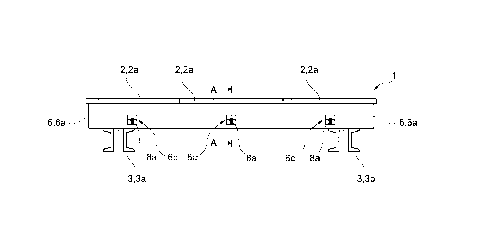
[0036] Fig. 1 is a plan view of a slab table 1 according to the invention for
at
least partial formworking of a concrete slab (not shown) that has at least one
formwork element 2 with a formwork element frame (not shown) and a form-
work skin 2a arranged on the formwork element frame.
[0037] As can be seen from Fig. 2, the slab table 1 further has a carrier skel-
eton 3 comprising a first main girder 3a and a second main girder 3b shown
in Fig. 3, wherein the longitudinal axis of the first main girder 3a runs
parallel
to the longitudinal axis of the second main girder 3b (see Fig. 3). In Fig. 2,
supports 4 are indicated that are accommodated in receptacles 5 or table
heads of the main girders 3a, 3b.
[0038] As can further be seen from Fig. 2, the slab table 1 has at least one
receiving device 6 or at least one cassette that is detachably fastened to the
carrier skeleton and in which the at least one formwork element 2 is detach-
ably received. The at least one receiving device 6 is provided with an in par-
ticular circumferential outer frame 6a and a base 6b - in particular, designed
as a lattice base (see Fig. 4). The at least one receiving device 6 can be
designed as a container, and in particular as a cassette or trough, and can
be formed, for example, from metal or plastic.
[0039] As can also be seen from Fig. 2, several receiving devices 6 fastened
to the carrier skeleton 3 can be connected to one another - in particular, via
a connecting element 7, shown in a simplified form.
[0040] As shown in Fig. 3, the at least one receiving device 6 or the outer
frame 6a of the at least one receiving device 6 can be detachably fastened
to the first main girder 3a and the second main girder 3b of the carrier skele-
ton 3, and detachably connect them to one another.
[0041] The at least one receiving device 6 can have a locking system 8 that
is designed for detachably fixing the at least one formwork element 2, and in
8
Date Recue/Date Received 2022-12-19
particular the formwork element frame 2b of the at least one formwork ele-
ment, in the receiving device 6 (see Figs. 3 through 6). As can be seen from
Figs. 3 through 6, one or more openings 6c for releasing the lock can be
present in the outer frame 6a of the at least one receiving device 6.
[0042] The locking system 8 can have a first fastening element 8a, and in
particular a securing hook or a securing catch, connected to the receiving
device 6 via a spring element 8c, which first fastening element is designed to
engage in a corresponding recess 2c on a first side 9 of the at least one
formwork element 2 or of the formwork element frame 2b of the at least one
formwork element 2. The spring element 8c can be designed as a tension
spring. A folding direction of the formwork elements 2 or panels is indicated
in a simplified manner in Fig. 4 by arrows 10.
[0043] As can be seen in more detail from Figs. 4 and 5, the locking system 8
further has a second fastening element 8b, and in particular a securing wedge
or the like, connected to the receiving device 6, which second fastening
element
is designed to engage in a corresponding recess 2d on a second side 11 of the
at least one formwork element 2 or of the formwork element frame 2b of the at
least one formwork element 2, which second side is opposite the first side 9.
[0044] The locking system 8 is shown in more detail in Fig. 5.
[0045] Fig. 6 shows, in a greatly simplified front view of the slab table 1, a
possibility for detachably fastening the at least one receiving device 6 to
the
first and second main girders 3a, 3b. Among other things, the formwork ele-
ments 2 and the main girders 3a, 3b in Fig. 6 are indicated only by dashed
lines. In this case, the at least one receiving device 6 can be pushed onto
the
main girders 3a, 3b, wherein a push-on element 12a and a locking element
12b ensure the detachable fastening.
List of reference signs:
9
Date Recue/Date Received 2022-12-19
I slab table
2 formwork element
2a formwork skin
2b formwork element frame
2c recess of the formwork element
2d recess of the formwork element
3 carrier skeleton
3a first main girder
3b second main girder
4 support
receptacles of the main girders
6 receiving device
6a outer frame
6b base
6c opening in the outer frame
7 connecting element
8 locking system
8a first fastening element
8b second fastening element
8c spring element
9 first side of the formwork element
arrow for folding direction
11 second side of the formwork element
12a push-on element
12b locking element
Date Recue/Date Received 2022-12-19