Note: Descriptions are shown in the official language in which they were submitted.
A VALVE INCLUDING AN EXPANDABLE METAL SEAL
CROSS-REFERENCE TO RELATED APPLICATION
[0001] This application claims priority to U.S. Application Serial No.
17/395,958, filed on
August 6, 2021, entitled "A VALVE INCLUDING AN EXPANDABLE METAL SEAL," which
claims the benefit of U.S. Provisional Application Serial No. 63/065,248,
filed on August 13,
2020, entitled "SWELLABLE METAL WIPER PLUG".
BACKGROUND
[0002] In cementing casing or liners (both referred to hereinafter as
"casing") in well bores (a
process known as primary cementing), a cement slurry is pumped downwardly
through the
casing to be cemented and then upwardly into the annulus between the casing
and the walls of
the well bore. Upon setting, the cement bonds the casing to the walls of the
well bore and
restricts fluid movement between formations or zones penetrated by the well
bore.
[0003] Prior to a primary cementing operation, the casing is suspended in a
well bore and both
the casing and the well bore are usually filled with drilling fluid. In order
to reduce
contamination of the cement slurry at the interface between it and the
drilling fluid, a
displacement plug for sealingly engaging the inner surfaces of the casing is
pumped ahead of the
cement slurry whereby the cement slurry is separated from the drilling fluid
as the cement slurry
and drilling fluid ahead of it are displaced through the casing. The
displacement plug wipes the
drilling fluid from the walls of the casing and maintains a separation between
the cement slurry
and drilling fluid until the plug lands on a float collar attached near the
bottom end of the casing.
[0004] The displacement plug, which precedes the cement slurry and separates
it from drilling
fluid is referred to herein as the "bottom plug." When the predetermined
required quantity of the
cement slurry has been pumped into the casing, a second displacement plug,
referred to herein as
the "top plug", is released into the casing to separate the cement slurry from
additional drilling
fluid or other displacement fluid used to displace the cement slurry. In
certain situations, the
bottom plug is not used, but the top plug is.
[0005] When the bottom plug lands on the float collar attached to the casing,
a valve mechanism
opens which allows the cement slurry to proceed through the plug and the float
collar upwardly
¨1 -
CA 03185552 2023- 1- 10
WO 2022/035704
PCT/US2021/045019
into the annular space between the casing and the well bore. The design of the
top plug is such
that when it lands on the bottom plug it shuts off fluid flow through the
cementing plugs which
prevents the displacement fluid from entering the annulus. After the top plug
lands, the pumping
of the displacement fluid into the casing is often continued whereby the
casing is pressured up
and the casing and associated equipment including the pump are pressure tested
for leaks or
other defects.
BRIEF DESCRIPTION
[0006] Reference is now made to the following descriptions taken in
conjunction with the
accompanying drawings, in which:
[0007] FIG. 1 illustrates a well system including an exemplary operating
environment that the
apparatuses, systems and methods disclosed herein may be employed;
[0008] FIGs. 2A and 2B illustrate a displacement plug for use in a wellbore
tubular designed and
manufactured according to one or more embodiments of the disclosure;
[0009] FIG. 3 illustrates is one embodiment of a displacement plug designed
and manufactured
according to one or more embodiments of the disclosure within a wellbore
tubular;
[0010] FIG. 4 illustrates the displacement plug of FIG. 3 after it has
expanded to form an
expanded displacement plug;
[0011] FIG. 5 illustrates an alternative embodiment of a displacement plug for
use in a wellbore
tubular designed and manufactured according to one or more embodiments of the
disclosure;
[0012] FIG. 6 illustrates an alternative embodiment of a displacement plug for
use in a wellbore
tubular designed and manufactured according to one or more embodiments of the
disclosure;
[0013] FIG. 7 illustrates an enlarged view of the displacement plug and the
wellbore tubular of
FIG. 6, clearly depicting the one or more plug member; and
[0014] FIG. 8 illustrates the displacement plug and the wellbore tubular of
FIG. 7 after the one
or more plug member have expanded to seal the flow path.
DETAILED DESCRIPTION
[0015] In the drawings and descriptions that follow, like parts are typically
marked throughout
the specification and drawings with the same reference numerals, respectively.
The drawn
figures are not necessarily to scale. Certain features of the disclosure may
be shown exaggerated
in scale or in somewhat schematic form and some details of certain elements
may not be shown
- 2 -
CA 03185552 2023- 1- 10
WO 2022/035704
PCT/US2021/045019
in the interest of clarity and conciseness. The present disclosure may be
implemented in
embodiments of different forms.
[0016] Specific embodiments are described in detail and are shown in the
drawings, with the
understanding that the present disclosure is to be considered an
exemplification of the principles
of the disclosure, and is not intended to limit the disclosure to that
illustrated and described
herein. It is to be fully recognized that the different teachings of the
embodiments discussed
herein may be employed separately or in any suitable combination to produce
desired results.
[0017] Unless otherwise specified, use of the terms "connect," "engage,"
"couple," "attach," or
any other like term describing an interaction between elements is not meant to
limit the
interaction to direct interaction between the elements and may also include
indirect interaction
between the elements described.
[0018] Unless otherwise specified, use of the terms "up," "upper," "upward,"
"uphole,"
-upstream," or other like terms shall be construed as generally toward the
surface of the ground;
likewise, use of the terms "down,- "lower," "downward," "downhole,- or other
like terms shall
be construed as generally toward the bottom, teiminal end of a well,
regardless of the wellbore
orientation. Use of any one or more of the foregoing terms shall not be
construed as denoting
positions along a perfectly vertical axis. Unless otherwise specified, use of
the term
"subterranean formation" shall be construed as encompassing both areas below
exposed earth
and areas below earth covered by water such as ocean or fresh water.
[0019] Referring to FIG. 1, depicted is a well system 100 including an
exemplary operating
environment that the apparatuses, systems and methods disclosed herein may be
employed. For
example, the well system 100 could include a pre or post expansion
displacement plug 180
according to any of the embodiments, aspects, applications, variations,
designs, etc. disclosed in
the following paragraphs. As depicted, the well system 100 includes a workover
and/or drilling
rig 110 that is positioned above the earth's smface 115 and extends over and
around a wellbore
120 that penetrates a subterranean formation 130 for the purpose of recovering
hydrocarbons.
The subterranean formation 130 may be located below exposed earth, as shown,
as well as areas
below earth covered by water, such as ocean or fresh water. As those skilled
in the art
appreciate, the wellbore 120 may be fully cased, partially cased, or an open
hole wellbore. In the
illustrated embodiment of FIG. 1, the wellbore 120 is partially cased, and
thus includes a cased
region 140 and an open hole region 145.
- 3 -
CA 03185552 2023- 1- 10
WO 2022/035704
PCT/US2021/045019
[0020] The wellbore 120 may be drilled into the subterranean formation 130
using any suitable
drilling technique. In the example illustrated in FIG. 1, the wellbore 120
extends substantially
vertically away from the earth's surface 115. Notwithstanding, in other
embodiments the
wellbore 120 could include a vertical wellbore portion, deviate from vertical
relative to the
earth's surface 115 over a deviated wellbore portion, and then transition to a
horizontal wellbore
portion. In alternative operating environments, all or portions of a wellbore
120 may be vertical,
deviated at any suitable angle, horizontal, and/or curved. The wellbore 120
may be a new
wellbore, an existing wellbore, a straight wellbore, an extended reach
wellbore, a sidetracked
wellbore, a multi-lateral wellbore, or any other type of wellbore for
drilling, completing, and /or
the production of one or more zones. Further, the wellbore 120 may be used for
both producing
wells and injection wells.
[0021] In accordance with the disclosure, the wellbore 120 may include a
wellbore tubular 150
(e.g., wellbore tubulars 150a, 150b). The wellbore tubular 150a. in the
illustrated embodiment,
is wellbore casing. The wellbore tubular 150b, in the illustrated embodiment,
is a liner.
Nevertheless, the present disclosure should not be limited to any specific
wellbore tubular. In
particular, the wellbore tubular may include any tubular having an annulus
that surrounds it, as
might be found with a concentric set of wellbore tubulars. The wellbore
tubular 150a, in the
illustrated embodiment of FIG. 1, is held in place by cement 160a in the cased
region 140. The
wellbore tubular 150b, in the illustrated embodiment of FIG. 1, is held in
place by cement 160b
in the open hole region 145.
[0022] In the illustrated embodiment of FIG. 1, a shoe track 170 has been
positioned at a lower
end of the wellbore tubular 150. The shoe track 170, in one embodiment,
includes a landing
collar 172, a float collar 174, and a float shoe 176. Nevertheless, other
designs for shoe tracks
are within the scope of the disclosure.
[0023] In the illustrated embodiment, the displacement plug 180 has landed
within the shoe track
170, and more specifically within the landing collar 172 of the shoe track.
The displacement
plug 180, pre-expansion, includes a plug body for landing in the wellbore
tubular, wherein at
least a portion of the plug body comprises a metal configured to expand in
response to hydrolysis
to seal against the wellbore tubular, and one or more displacement features
engaged with the
plug body for displacing the plug body downhole. The displacement plug 180,
post-expansion,
- 4 -
CA 03185552 2023- 1- 10
WO 2022/035704
PCT/US2021/045019
includes a cement plug body locked in the wellbore tubular, and one or more
displacement
features engaged with the cement plug body.
[0024] As briefly indicated above, the expandable metal (e.g., in at least on
embodiment)
automatically, and without intervention, expands in response to hydrolysis to
lock the
displacement plug 180 in place. Accordingly, what results are one or more
expanded metal
sections of the displacement plug 180. The term expandable metal, as used
herein, refers to the
expandable metal in a pre-expansion form. Similarly, the term expanded metal,
as used herein,
refers to the resulting expanded metal after the expandable metal has been
subjected to reactive
fluid, as discussed below. Additionally, the term partially expanded metal, as
used herein, refers
to the resulting expanded metal after a portion of the expandable metal has
been subjected to
reactive fluid, as discussed below.
[0025] The expanded metal, in accordance with one or more aspects of the
disclosure, comprises
a metal that has expanded in response to hydrolysis. In certain embodiments,
the expanded
metal includes residual unreacted metal, such as when it is partially expanded
metal. For
example, in certain embodiments the expanded metal is intentionally designed
to include the
residual unreacted metal. The residual unreacted metal has the benefit of
allowing the expanded
metal to self-heal if cracks or other anomalies subsequently arise, or for
example to
accommodate changes in the tubular or mandrel diameter due to variations in
temperature and/or
pressure. Nevertheless, other embodiments may exist wherein no residual
unreacted metal exists
in the expanded metal.
[0026] The expandable metal, in some embodiments, may be described as
expanding to a cement
like material. In other words, the expandable metal goes from metal to micron-
scale particles
and then these particles expand and lock together to, in essence, seal two or
more surfaces
together. The reaction may, in certain embodiments, occur in less than 2 days
in a reactive fluid
and in certain temperatures. Nevertheless, the time of reaction may vary
depending on the
reactive fluid, the expandable metal used, the downhole temperature, and
surface-area-to-volume
ratio (SA:V) of the expandable metal.
[0027] In some embodiments, the reactive fluid may be a brine solution such as
may be
produced during well completion activities, and in other embodiments, the
reactive fluid may be
one of the additional solutions discussed herein, including drilling fluid
and/or cement slurry.
The metal, pre-expansion, is electrically conductive in certain embodiments.
The metal may be
- 5 -
CA 03185552 2023- 1- 10
WO 2022/035704
PCT/US2021/045019
machined to any specific size/shape, extruded, formed, cast or other
conventional ways to get the
desired shape of a metal, as will be discussed in greater detail below. Metal,
pre-expansion, in
certain embodiments has a yield strength greater than about 8,000 psi, e.g.,
8,000 psi +/- 50%. It
has been measured that the post expansion displacement plug 180 can hold over
3,000 psi in a
41/2" tubing with an 18" long plug, which is about 160 psi per inch. In
certain other
embodiments, the displacement plug 180 may hold at least 300 psi per inch of
plug length.
[0028] The hydrolysis of the expandable metal can create a metal hydroxide.
The formative
properties of alkaline earth metals (Mg - Magnesium, Ca - Calcium, etc.) and
transition metals
(Zn ¨ Zinc, Al - Aluminum, etc.) under hydrolysis reactions demonstrate
structural
characteristics that are favorable for use with the present disclosure.
Hydration results in an
increase in size from the hydration reaction and results in a metal hydroxide
that can precipitate
from the fluid.
[0029] The hydration reactions for magnesium is:
Mg + 2H20 Mg(OH)2 + H2,
where Mg(OH)2 is also known as brucite. Another hydration reaction uses
aluminum hydrolysis.
The reaction forms a material known as Gibbsite, bayerite, boehmite, aluminum
oxide, and
norstrandite, depending on form. The possible hydration reactions for aluminum
are:
Al + 31120 Al(OH)3 + 3/2 1-12.
Al + 2H20 -> Al 0(OH) + 3/2 H2
Al + 3/2 1420 -> 1/2 A1203 + 3/2 FI2
Another hydration reaction uses calcium hydrolysis. The hydration reaction for
calcium is:
Ca + 2H20 Ca(OH)2 + H2,
Where Ca(OH)2 is known as portlandite and is a common hydrolysis product of
Portland cement.
Magnesium hydroxide and calcium hydroxide are considered to be relatively
insoluble in water.
Aluminum hydroxide can be considered an amphotcric hydroxide, which has
solubility in strong
acids or in strong bases. Alkaline earth metals (e.g., Mg, Ca, etc.) work well
for the expandable
metal, but transition metals (Al, etc.) also work well for the expandable
metal. In one
embodiment, the metal hydroxide is dehydrated by the swell pressure to form a
metal oxide.
- 6 -
CA 03185552 2023- 1- 10
WO 2022/035704
PCT/US2021/045019
[0030] In an embodiment, the expandable metal used can be a metal alloy. The
expandable metal
alloy can be an alloy of the base expandable metal with other elements in
order to either adjust
the strength of the expandable metal alloy, to adjust the reaction time of the
expandable metal
alloy, or to adjust the strength of the resulting metal hydroxide byproduct,
among other
adjustments. The expandable metal alloy can be alloyed with elements that
enhance the strength
of the metal such as, but not limited to, Al - Aluminum, Zn - Zinc, Mn -
Manganese, Zr -
Zirconium, Y - Yttrium, Nd - Neodymium, Gd - Gadolinium, Ag - Silver, Ca -
Calcium, Sn -
Tin, and Re ¨ Rhenium, Cu ¨ Copper. In some embodiments, the expandable metal
alloy can be
alloyed with a dopant that promotes corrosion, such as Ni - Nickel, Fe - Iron,
Cu - Copper, Co -
Cobalt, Ir - Iridium, Au - Gold, C ¨ Carbon, Ga - Gallium, In - Indium, Mg -
Mercury, Bi -
Bismuth, Sn - Tin, and Pd - Palladium. The expandable metal alloy can be
constructed in a solid
solution process where the elements are combined with molten metal or metal
alloy.
Alternatively, the expandable metal alloy could be constructed with a powder
metallurgy
process. The expandable metal can be cast, forged, extruded, sintered, welded,
mill machined,
lathe machined, stamped, eroded or a combination thereof. The metal alloy can
be a mixture of
the metal and metal oxide. For example, a powder mixture of aluminum and
aluminum oxide can
be ball-milled together to increase the reaction rate.
[0031] Optionally, non-expanding components may be added to the starting
metallic materials.
For example, ceramic, elastomer, plastic, epoxy, glass, or non-reacting metal
components can be
embedded in the expandable metal or coated on the surface of the expandable
metal. In yet other
embodiments, the non-expanding components are metal fibers, a composite weave,
a polymer
ribbon, or ceramic granules, among others. Alternatively, the starting
expandable metal may be
the metal oxide. For example, calcium oxide (CaO) with water will produce
calcium hydroxide
in an energetic reaction. Due to the higher density of calcium oxide, this can
have a 260%
volumetric expansion (e.g., converting 1 mole of CaO may cause the volume to
increase from
9.5cc to 34.4cc). In one variation, the expandable metal is formed in a
serpentinite reaction, a
hydration and metamorphic reaction. In one variation, the resultant material
resembles a mafic
material. Additional ions can be added to the reaction, including silicate,
sulfate, aluminate,
carbonate, and phosphate. The metal can be alloyed to increase the reactivity
or to control the
formation of oxides.
- 7 -
CA 03185552 2023- 1- 10
WO 2022/035704
PCT/US2021/045019
[0032] The expandable metal can be configured in many different fashions, as
long as an
adequate volume of material is available for setting the displacement plug
180. For example,
the expandable metal may be formed into a single long member, multiple short
members, rings,
among others. In another embodiment, the expandable metal may be formed into a
long wire of
expandable metal, that can be in turn be wound around a tubular as a sleeve.
The wire diameters
do not need to be of circular cross-section, but may be of any cross-section.
For example, the
cross-section of the wire could be oval, rectangle, star, hexagon, keystone,
hollow braided,
woven, twisted, among others, and remain within the scope of the disclosure.
In certain other
embodiments, the expandable metal is a collection of individual separate
chunks of the metal
held together with a binding agent. In yet other embodiments, the expandable
metal is a
collection of individual separate chunks of the metal that are not held
together with a binding
agent, but held in place using one or more different techniques. In at least
one other
embodiment, one or more of the displacement features of the displacement plug
180 comprise
the expandable metal.
[0033] Additionally, a delay coating may be applied to one or more portions of
the expandable
metal to delay the expanding reactions. In one embodiment, the material
configured to delay the
hydrolysis process is a fusible alloy. In another embodiment, the material
configured to delay
the hydrolysis process is a eutectic material. In yet another embodiment, the
material configured
to delay the hydrolysis process is a wax, oil, or other non-reactive material.
[0034] Turning to FIGs. 2A and 2B, illustrated is a displacement plug 200
(e.g., pre-expansion
displacement plug) for use in a wellbore tubular designed and manufactured
according to one or
more embodiments of the disclosure. FIG. 2A illustrates a cross-sectional view
of the
displacement plug 200, whereas FIG. 2B illustrated an isometric view of the
displacement plug
200. With reference to FIG. 2A, the displacement plug 200 includes a plug body
210, wherein at
least a portion of the plug body 210 comprises a metal configured to expand in
response to
hydrolysis to seal against a wellbore tubular, as discussed above. In the
illustrated embodiment
of FIG. 2A, the plug body 210 includes a nose 212 having a nose shoulder 214,
a nose nut 216, a
tubular 218 (e.g., mandrel in one embodiment), a lock ring 220, and an 0-ring
222. Any one or
more of the nose 212, nose nut 216, tubular 218, and/or lock ring 220 may
comprise the
expandable metal. While the plug body 210 has been illustrated as having a
variety of different
features, any plug body according to the disclosure could be used.
- 8 -
CA 03185552 2023- 1- 10
WO 2022/035704
PCT/US2021/045019
[0035] Engaged with the plug body 210 are one or more displacement features
230. In at least
one embodiment, the one or more displacement features are displacement fins.
In yet another
embodiment, the one or more displacement features are one or more compressible
features, such
as compressible (e.g., foam) drop balls. The one or more displacement features
230, in one
embodiment, comprise rubber. The one or more displacement features 230, in
another
embodiment, comprise plastic or metal. In yet another embodiment, the one or
more
displacement features 230 comprise a foam material. In yet another embodiment,
at least one of
the one or more displacement features 230 comprises a metal configured to
expand in response
to hydrolysis, as discussed above. While the one or more displacement features
230 have been
illustrated with a wiper like shape, other embodiments exist wherein a non-
wiper like shape is
used, such as when balls are used.
[0036] The nose nut 216 may have a variety of different outside diameters (D)
and remain
within the scope of the disclosure. In one embodiment, the nose nut 216 has a
diameter (Do)
ranging from 3.4 inches to 17.5 inches. The tubular 218 may have a variety of
different inside
diameters (Dm) and remain within the scope of the disclosure. In one
embodiment, the tubular
218 has a diameter (Dm) ranging from 1.5 inches to 7.5 inches. The lock ring
220 may have a
variety of different outside diameters (DO and remain within the scope of the
disclosure. In one
embodiment, the lock ring 220 has a diameter (DO ranging from 3.7 inches to
18.5 inches. The
one or more displacement features 230 may have a variety of different outside
diameters (Df) and
remain within the scope of the disclosure. In one embodiment, the one or more
displacement
features 230 have a diameter (Di') ranging from 5.5 inches to 27.5 inches. The
displacement plug
200 may have a variety of different lengths (L) and remain within the scope of
the disclosure. In
one embodiment, the displacement plug 200 has a length (L) ranging from 4
inches to 72 inches,
and in another embodiment has a length (L) ranging from 8 inches to 36 inches.
[0037] Turning to FIG. 3, illustrated is one embodiment of a displacement plug
300 designed
and manufactured according to one or more embodiments of the disclosure within
a wellbore
tubular 350. The displacement plug 300, in one embodiment, is similar to the
displacement plug
200 of FIGs. 2A and 2B. The wellbore tubular 350, in the illustrated
embodiment, is a landing
plug, nevertheless other wellbore tubulars might be used. Turning to FIG. 4,
illustrated is the
displacement plug 300 of FIG. 3 after it has expanded to form an expanded
displacement plug
410.
- 9 -
CA 03185552 2023- 1- 10
WO 2022/035704
PCT/US2021/045019
[0038] Turning to FIG. 5, illustrated is an alternative embodiment of a
displacement plug 500 for
use in a wellbore tubular 550 designed and manufactured according to one or
more embodiments
of the disclosure. The displacement plug 500, in the illustrated embodiment,
comprises a first
casing displacement plug 510 and a second drill pipe displacement plug 520. In
accordance with
the disclosure, each of the casing displacement plug 510 and the drill pipe
displacement plug 520
may include a plug body, wherein at least a portion of the plug body comprises
a metal
configured to expand in response to hydrolysis to seal against a wellbore
tubular.
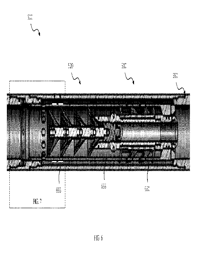
[0039] Turning to FIG. 6, illustrated is an alternative embodiment of a
displacement plug 600 for
use in a wellbore tubular 650 designed and manufactured according to one or
more embodiments
of the disclosure. The displacement plug 600 is similar in many respects to
the displacement
plug 500 of FIG. 5. Accordingly, like reference numbers have been used to
indicate similar, if
not substantially identical, features. The displacement plug 600 differs, for
the most part, from
the displacement plug 500, in that the wellbore tubular 650 is a wet shoe sub.
Accordingly, the
wellbore tubular 650 has a sliding sleeve 655 disposed therein, the sliding
sleeve 655 configured
to slide to open a flow path 660 below the plug body. The wellbore tubular
650, in the illustrated
embodiment, further includes one or more plug members 665 positioned within
the flow path
660, the one or more plug members 665 comprising the metal configured to
expand in response
to hydrolysis to seal the flow path. The plug member 665 metal may be similar
to one or more
of those discussed above.
[0040] Turning to FIG. 7. illustrated is an enlarged view of the displacement
plug 600 and the
wellbore tubular 650, clearly depicting the one or more plug member 665.
Turning to FIG. 8,
illustrated are the displacement plug 600 and the wellbore tubular 650 of FIG.
7 after the one or
more plug member 665 have expanded to seal the flow path 660. What results are
one or more
expanded plug members 865.
[0041] The present disclosure has discussed the one or more plug members 665
as being used
with the displacement plug 600, however, certain embodiments exist wherein the
one or more
plug members 665 comprising a metal configured to expand in response to
hydrolysis could be
used to seal any flow path, but particularly any flow path in an annulus
between a sliding sleeve
and a wellbore tubular and/or mandrel.
[0042] Aspects disclosed herein include:
- 10 -
CA 03185552 2023- 1- 10
WO 2022/035704
PCT/US2021/045019
A. A displacement plug for use in a wellbore tubular, the displacement plug
including: 1)
a plug body for landing in a wellbore tubular, wherein at least a portion of
the plug body
comprises a metal configured to expand in response to hydrolysis to seal
against the wellbore
tubular; and 2) one or more displacement features engaged with the plug body
for displacing the
plug body downhole.
B. A method for entering a well system, the method including: 1) pumping fluid
within a
wellbore tubular; 2) positioning a displacement plug in the wellbore tubular
after pumping the
fluid, the displacement plug landing in the wellbore tubular, the displacement
plug including: a)
a plug body for landing in the wellbore tubular, wherein at least a portion of
the plug body
comprises a metal configured to expand in response to hydrolysis to seal
against the wellbore
tubular; and 3) subjecting the displacement plug to a wellbore fluid, thereby
forming an
expanded displacement plug fixed in the wellbore tubular, the expanded
displacement plug
including a cement plug body.
C. A well system, the well system including: 1) a wellbore positioned in a
subterranean
formation; 2) a wellbore tubular positioned within the wellbore, an annulus
existing between the
wellbore tubular and the wellbore; 3) an expanded displacement plug fixed in
the wellbore
tubular, the expanded displacement plug including a cement plug body and one
or more
displacement features engaged with the cement plug body; and 4) cement
positioned in the
annulus.
D. A valve, the valve including: 1) a housing; 2) a sliding sleeve disposed in
the housing
and defining an annular flow path between the sliding sleeve and the housing,
the sliding sleeve
configured to move from a closed positioned closing the annular flow path to
an open position
opening the flow path; and 3) a plug member positioned within the annular flow
path, the plug
member comprising a metal configured to expand in response to hydrolysis to
seal the annular
flow path.
E. A method for sealing, the method including: 1) positioning a valve within a
wellbore
tubular, the valve including; a) a housing; b) a sliding sleeve disposed in
the housing and
defining an annular flow path between the sliding sleeve and the housing, the
sliding sleeve
configured to move from a closed positioned closing the annular flow path to
an open position
opening the flow path; and CO a plug member positioned within the flow path,
the plug member
comprising a metal configured to expand in response to hydrolysis to seal the
annular flow path;
- 1 1 -
CA 03185552 2023- 1- 10
WO 2022/035704
PCT/US2021/045019
2) pumping cement within a wellbore tubular; and 3) subjecting the plug member
to a reactive
fluid, thereby forming an expanded metal plug member in the annular flow path.
F. A well system, the well system including: 1) a wellbore positioned in a
subterranean
formation; and 2) a valve positioned within the wellbore, the valve including;
a) a housing; b) a
sliding sleeve disposed in the housing and defining an annular flow path
between the sliding
sleeve and the housing, the sliding sleeve configured to move from a closed
positioned closing
the annular flow path to an open position opening the flow path; and c) an
expanded metal plug
member positioned within the annular flow path, the expanded metal plug member
comprising a
metal that has expanded in response to hydrolysis to seal the annular flow
path.
[0043] Aspects A, B. C, D, E, and F may have one or more of the following
additional elements
in combination: Element 1: wherein the plug body includes a nose, wherein at
least a portion of
the nose comprises the metal configured to expand in response to hydrolysis.
Element 2:
wherein the nose includes a nose nut, the nose nut comprising the metal
configured to expand in
response to hydrolysis. Element 3: wherein the nose includes a tubular, the
tubular comprising
the metal configured to expand in response to hydrolysis. Element 4: wherein
the nose includes
a lock ring, the lock ring comprising the metal configured to expand in
response to hydrolysis.
Element 5: wherein the nose includes an 0-ring. Element 6: wherein the plug
body is a casing
displacement plug body. Element 7: wherein the plug body is a drill pipe
displacement plug
body. Element 8: wherein the one or more displacement features are one or more
displacement
fins. Element 9: wherein the one or more displacement fins are coupled to the
plug body.
Element 10: wherein the displacement plug further includes one or more
displacement features
engaged with the plug body. Element 11: wherein pumping fluid within the
wellbore tubular
includes pumping cement within the wellbore tubular. Element 12: wherein the
one or more
displacement fins are coupled to the cement plug body. Element 13: wherein the
wellbore
tubular is a landing collar. Element 14: wherein the landing collar is a
landing collar of a shoe
track. Element 15: wherein the shoe track includes a float collar and a float
shoe. Element 16:
wherein the landing collar is wellbore casing. Element 17: wherein the landing
collar is a wet
shoe sub having a sliding sleeve disposed therein, the sliding sleeve
configured to slide to open a
flow path below the plug body. Element 18: further including one or more plug
members
positioned within the flow path, the plug member comprising a metal configured
to expand in
response to hydrolysis to seal the flow path. Element 19: wherein the plug
member is configured
-12 -
CA 03185552 2023- 1- 10
WO 2022/035704
PCT/US2021/045019
to be protected from reactive fluid when the sliding sleeve is in the closed
position and
configured to be exposed to the reactive fluid when the sliding sleeve is in
the open position.
Element 20: wherein the plug member is a first plug member, and further
including a second
plug member positioned within the flow path, the second plug member comprising
the metal
configured to expand in response to hydrolysis. Element 21: wherein the
housing and the sliding
sleeve form at least a portion of a wet shoe sub. Element 22: further
including a displacement
plug positioned within the sliding sleeve. Element 23: wherein the
displacement plug includes: a
plug body for landing in the sliding sleeve, wherein at least a portion of the
plug body comprises
a metal configured to expand in response to hydrolysis to seal against the
wellbore tubular; and
one or more displacement fins coupled to the plug body for displacing the plug
body downhole.
Element 24: wherein the subjecting occurs after the sliding sleeve has been
moved from the
closed position to the open position. Element 25: wherein the reactive fluid
is drilling fluid.
Element 26: wherein the reactive fluid is cement slurry. Element 27: wherein
the housing and
the sliding sleeve form at least a portion of a wet shoe sub. Element 28:
wherein the expanded
metal plug member fixes the sliding sleeve in the open position. Element 29:
wherein the
housing and the sliding sleeve form at least a portion of a wet shoe sub.
Element 30: further
including a displacement plug located within the sliding sleeve, and further
wherein the
displacement plug includes a plug body landed in the sliding sleeve, and one
or more
displacement fins coupled to the plug body for displacing the plug body
downhole.
[0944] Those skilled in the art to which this application relates will
appreciate that other and
further additions, deletions, substitutions and modifications may be made to
the described
embodiments.
- 1 3 -
CA 03185552 2023- 1- 10