Note: Descriptions are shown in the official language in which they were submitted.
WO 2022/012944
PCT/EP2021/068142
1
A facility and a membrane process for separating methane and carbon dioxide
from a gas
stream
Field of the invention
[001] The invention is directed at a membrane process and a facility for
separating methane and
carbon dioxide from a gas stream, providing a methane stream suitable for
injection into a natural
gas grid, which can achieve low emission of methane to the atmosphere with
little extra equipment
and energy consumption.
Background of the invention
[002] Biogas resulting from anaerobic fermentation, such as biogas from an
anaerobic digester
or a landfill gas, comprises methane and carbon dioxide as the major
components. Separating
methane from biogas in a quality suitable for feeding the methane into a gas
distribution grid is of
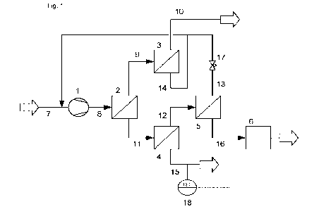
commercial interest. Membrane processes are advantageous for separating
methane from carbon
dioxide as they do not require an absorbent for carbon dioxide and can be
operated with low
energy consumption. Since methane is a more potent greenhouse gas than carbon
dioxide, the
carbon dioxide enriched stream obtained by a membrane separation process can
only be
discharged to the atmosphere if it is separated with a low methane content or
subjected to an
additional treatment for methane removal. Such additional treatment for
methane removal
consumes energy and requires extra equipment.
[003] WO 2012/000727 discloses a membrane process with three membrane units
which can
separate biogas into a biomethane stream containing more than 98 vol-% methane
and a carbon
dioxide enriched stream containing about 0.5 % methane at a low recycle rate
of less than 60 %
which makes the process energy efficient.
[004] WO 2015/036709 discloses a membrane process with four membrane units
which aims at
further reducing the energy required for compressing recycled gas but provides
a lower methane
recovery compared to the process of WO 2012/000727. The process provides two
carbon dioxide
enriched streams from the third and the fourth membrane unit. WO 2015/036709
suggests that
these two streams may be separately or jointly treated by thermal oxidation,
used for upgrading the
carbon dioxide or discharged to the atmosphere.
[005] At September 24, 2018 the Oil and Gas Climate Initiative (OGCI)
published a first methane
emission target for its member companies. A base line for methane that gets
lost when producing
oil and gas of max. 0.32 % and a target of 0.25% methane loss for 2025 was
set.
[006] Tightened regulations on emission of greenhouse gases, e.g. 36 of the
German "42.
Verordnung Ciber den Zugang zu Gasversorgungsnetzen (Gasnetzzugangsverordnung
¨
GasNZV)", require even more ambitious targets for lowering methane emissions
from biogas
CA 03185947 2023- 1- 12
WO 2022/012944
PCT/EP2021/068142
2
upgrading or natural gas purification (max. 0.2 %). The prior art membrane
processes can achieve
such goals only by significantly high recycle rates or by an additional step
of removing methane
from the carbon dioxide enriched streams before discharge to the atmosphere.
Both measures
increase costs and decrease efficiency of the prior art processes.
[007] Therefore, a strong need remains for an efficient process for separating
methane and
carbon dioxide from a gas stream, which fulfills the requirement of the
tightened regulations on
emissions of greenhouse gases with little extra equipment and energy
consumption.
[008] Subject of the present invention was to provide a new facility and a new
process having the
disadvantages of the prior art processes and facilities to a reduced degree
respectively not having
the disadvantages of the prior art processes and facilities.
[009] A specific problem of the present invention was to provide a new
facility and a new process
for separating methane and carbon dioxide from a gas stream, which fulfills
the requirements of
tightened regulations on emissions of greenhouse gases, in particular with
regard to gas streams
that are discharged to the atmosphere and that should have a methane content
of below or equal
to 0.3 `)/0 by volume, preferably below or equal to 0.2% by volume.
[010] Another specific problem of the present invention was to provide a new
facility and a new
process for separating methane and carbon dioxide from a gas stream, wherein
at least one
carbon dioxide enriched stream, that is discharged to the atmosphere, is
provided having a
methane content of below or equal to 0.3 % by volume, preferably 0.2% by
volume, without
oxidative, methan removing post treatment step.
[011] In another specific problem of the present invention a new facility
and a new process for
upgrading a gas comprising methane and carbon dioxide shall be provided,
wherein a methane
product stream having a methane content of more than or equal to 97 cYo by
volume can be
obtained and simultaneously a methane yield higher than disclosed in WO
2015/036709 Al can be
achieved.
[012] In another specific problem of the present invention a new facility
and a new process for
upgrading a gas comprising methane and carbon dioxide shall be provided, which
are highly
efficient in view of operating costs and/or invest costs. Preferably the
invest and/or operating costs
for gas recompression and/or post treatment of off-gas streams to reduce the
methane content
shall be minimized.
[013] In another specific problem of the present invention a new facility
and a new process for
upgrading a gas comprising methane and carbon dioxide shall be provided,
allowing to
continuously fulfill regulatory requirements with regard to methane emission
to the atmosphere
even if the composition and/or flow rate of the raw gas stream vary.
[014] Further problems solved by the present invention but not described
before, can be derived
from the subsequent description, examples, figures and claims.
CA 03185947 2023- 1- 12
WO 2022/012944
PCT/EP2021/068142
3
Summary of the invention
[015] The inventor of the present invention has now surprisingly found that
the problems
described above, can be solved by using a membrane separation facility with
four membrane units
as known from WO 2015/036709, which facility has been modified by
a. connecting only the permeate outlet of the fourth membrane unit to a
methane oxidation unit
and discharging the permeate from the third membrane unit directly to the
atmosphere,
b. configuring and operating the facility to provide a carbon dioxide
concentration in the first
permeate stream of from 90 to 99 % by volume,
c. using membranes with a pure gas selectivity for carbon dioxide over methane
of at least 30,
determined at 20 C and 5 bar, in the first membrane separation unit.
[016] The facility and the process of the invention allow for
adhering to strict regulatory
requirements for methane emission to the atmosphere for both, the third and
fourth permeate
stream, even if the third permeate stream is not subjected to methane removing
post treatment and
directly discharged to the atmosphere. As shown in Comparative Examples la and
lb below, the
process of WO 2015/036709 Al, does not disclose any facility or process
wherein a third permeate
stream with a methane content of 0.3 Vol. % is provided without oxidative post
treatment.
[017] The achievement to provide a third permeate stream with a methane
content of 0.3 Vol. `)/0
or below after the membrane separation allows to reduce invest costs for
equipment for oxidative
methane removal in the facility and process of the invention. Also, the
operating costs for methane
removal could be reduced compared to the prior art. In preferred embodiments
of the invention it
was in addition achieved to minimize the volume flow of the fourth permeate
stream, which enables
to further reduce the capacities for oxidative post-treatment and to further
reduce invest and
operating costs.
[018] Compared to prior art processes the facility and process of the
invention can be operated
at with minimum cost for recompression even though tightened requirements for
methane emission
to the atmosphere are fulfilled.
[019] Preferably the facility and process of the invention
comprise means for direct or indirect
measurement and/or means for controlling the methane concentration in the
third permeate
stream. In preferred embodiments the operating conditions of the first
membrane unit of the facility
are adjusted based on direct or indirect measuring the methane concentration
in the third permeate
stream. This allows to continuously provide a third permeate stream having a
methane
concentration of 0.3 Vol% or below even if the composition and/or flow rate of
the raw gas stream
change. Facility and process of the invention can therefore be used flexibly
for different raw gas
sources and raw gas sources with varying amounts and/or composition of the raw
gas.
[020] Process and facility of the invention provide methane product stream
having very high
methane contents and very high methane yield.
CA 03185947 2023- 1- 12
WO 2022/012944
PCT/EP2021/068142
4
[021] Further advantages of the facility and the process of the invention
are revealed in the
subsequent description, examples, figures and claims.
[022] Subject of the invention is therefore a facility for separating
methane and carbon dioxide
from a gas stream, which facility comprises
a compressor (1);
four membrane separation units (2) to (5), each membrane separation unit
comprising a gas
separation membrane having higher permeance for carbon dioxide than for
methane, a gas inlet, a
retentate outlet and a permeate outlet;
a methane oxidation unit (6);
a raw gas conduit (7) connected to an inlet of the compressor (1);
a feed conduit (8) connecting an outlet of the compressor (1) with the gas
inlet of the first
membrane separation unit (2);
a first retentate conduit (9) connecting the retentate outlet of the first
membrane separation unit (2)
to the gas inlet of the second membrane separation unit (3);
a second retentate conduit (10) connected to the retentate outlet of the
second membrane
separation unit (3);
a first permeate conduit (11) connecting the permeate outlet of the first
membrane separation unit
(2) to the gas inlet of the third membrane separation unit (4);
a third retentate conduit (12) connecting the retentate outlet of the third
membrane separation unit
(4) to the gas inlet of the fourth membrane separation unit (5);
a fourth retentate conduit (13) connecting the retentate outlet of the fourth
membrane separation
unit (5) to an inlet of the compressor (1);
a second permeate conduit (14) connecting the permeate outlet of the second
membrane
separation unit (3) to an inlet of the compressor (1);
a third permeate conduit (15) connected to the permeate outlet of the third
membrane separation
unit (4); and
a fourth permeate conduit (16) connected to the permeate outlet of the fourth
membrane
separation unit (5)
characterized in that
the third permeate conduit (15) is configured to discharge the third permeate
to the surrounding
atmosphere;
the fourth permeate conduit (16) connects the permeate outlet of the fourth
membrane separation
unit (5) to the methane oxidation unit (6);
the first membrane separation unit (2) comprises a membrane with a with a pure
gas selectivity for
carbon dioxide over methane, determined at 20 C and 5 bar, of at least 30,
preferably of from 40 to
120 and more preferably of from 50 to 100;
the facility is configured to provide a carbon dioxide concentration in the
gas stream in the first
permeate conduit (11), the first permeate stream, in a range of from 90 to 99
`)/0 by volume.
CA 03185947 2023- 1- 12
WO 2022/012944
PCT/EP2021/068142
[023] A further subject of the invention is a membrane process for separating
methane and
carbon dioxide from a gas stream, which process comprises
a) providing a facility of the invention;
b) introducing a raw gas stream, containing from 20 to 60 % by volume,
preferably 20 to 50 % by
5 volume, carbon dioxide and having a combined content of methane and
carbon dioxide of at
least 95 % by volume, into the raw gas conduit (7) of said facility;
c) compressing the raw gas stream combined with recycle streams from the
fourth retentate
conduit (13) and the second permeate conduit (14) with compressor (1) to
provide a feed
stream at a feed pressure of from 7 to 25 bar and a temperature of from 15 to
50 C;
d) separating the feed stream in the first membrane separation unit (2) into a
first permeate
stream and a first retentate stream, using a membrane with a mixed gas
selectivity for carbon
dioxide over methane of at least 30, preferably of from 40 to 100, at the feed
pressure and the
temperature of the feed stream, and selecting permeate side pressure in the
first membrane
separation unit and separation capacities in the four membrane separation
units to provide a
carbon dioxide concentration in the first permeate stream of from 90 to 99
`)/0 by volume, the
separation capacity of a membrane separation unit being the product of the
membrane area
and the membrane permeance for carbon dioxide at a temperature of 25 C and a
feed side
pressure of 5 bar;
e) separating the first retentate stream in the second membrane separation
unit (3) into a second
retentate stream and a second permeate stream, further processing the second
retentate
stream or withdrawing the second retentate stream as a methane rich product
stream and
recycling the second permeate stream through the second permeate conduit (14);
0 separating the first permeate stream in the third membrane
separation unit (4) into a third
retentate stream and a third permeate stream, discharging the third permeate
stream to the
surrounding atmosphere without further methane removal;
g) separating the third retentate stream in the fourth membrane separation
unit (5) into a fourth
retentate stream and a fourth permeate stream, recycling the fourth retentate
stream through
the retentate conduit (13); and
h) oxidizing the fourth permeate stream in the methane oxidation unit (6) to
provide an off-gas
stream containing less than 0.3 % by volume methane, which off-gas stream is
discharged to
the surrounding atmosphere.
Brief description of drawings
[024] Fig. 1 shows an embodiment of the facility of the invention where a
methane concentration
sensor (18) connected to the third permeate conduit (15) controls a pressure
regulating valve (17)
arranged in the fourth retentate conduit (13).
[025] Fig. 2 shows an embodiment of the facility of the invention where
methane concentration
sensor (18) controls a flow regulating valve (20) in a conduit passing a
heating or cooling fluid to a
heat exchanger (19) in the feed conduit (8).
CA 03185947 2023- 1- 12
WO 2022/012944
PCT/EP2021/068142
6
[026] Fig. 3 shows an embodiment of the facility of the invention where the
first membrane
separation unit (2) comprises an additional permeate outlet and methane
concentration sensor (18)
controls a flow regulating valve (22) arranged in an additional conduit (21)
connecting the additional
permeate outlet with the gas inlet of the fourth membrane separation unit (5).
Detailed description of the invention
[027] The facility of the invention for separating methane and carbon dioxide
from a gas stream
comprises a compressor (1) and a raw gas conduit (7) connected to an inlet of
the compressor (1).
Any gas compressor known to be suitable for compressing mixtures containing
methane and
carbon dioxide may be used, such as a turbo compressor, a piston compressor or
preferably a
screw compressor. The screw compressor may be a dry running compressor, or a
fluid-cooled
compressor cooled with water or oil. When an oil cooled compressor is used,
the facility preferably
also contains a droplet separator downstream of the compressor to prevent oil
droplets from
entering a membrane separation stage.
[028] The facility of the invention comprises four membrane separation units
(2) to (5). Each of
the membrane separation units comprises a gas separation membrane having
higher permeance
for carbon dioxide than for methane, as well as a gas inlet, a retentate
outlet and a permeate outlet.
The term permeate here refers to a gas stream comprising the gas components of
the gas stream
fed to the membrane separation unit which have passed the gas separation
membrane due to the
difference in partial pressure across the membrane. The term retentate refers
to the gas stream
which remains after the gas components have passed the gas separation
membrane. Since the
gas separation membrane has higher permeance for carbon dioxide than for
methane, the
permeate will have a higher molar ratio of carbon dioxide to methane than the
gas stream fed to
the membrane separation unit, i.e. it will be enriched in carbon dioxide, and
the retentate will have
a higher molar ratio of methane to carbon dioxide than the gas stream fed to
the membrane
separation unit, i.e. it will be enriched in methane.
[029] Suitable membranes which have higher permeability for carbon dioxide
than for methane
are known from the prior art. In general, membranes containing a separation
layer of a glassy
polymer, i.e. a polymer having a glass transition point at a temperature above
the operating
temperature of the membrane separation stage, will provide higher permeability
for carbon dioxide
than for methane. The glassy polymer may be a polyetherimide, a polycarbonate,
a polyamide, a
polybenzoxazole, a polybenzimidazole, a polysulfone or a polyimide and the gas
separation
membrane preferably comprises at least 80 % by weight of a polyimide or a
mixture of polyimides.
[030] In a preferred embodiment, the gas separation membrane comprises at
least 50 % by
weight of a polyimide prepared by reacting a dianhydride selected from
3,4,3',4'-benzophenonetetracarboxylic dianhydride, 1,2,4,5-
benzenetetracarboxylic dianhydride,
3,4,3',4'-biphenyltetracarboxylic dianhydride, oxydiphthalic dianhydride,
sulphonyldiphthalic
dianhydride, 1,1,1,3,3,3-hexafluoro-2,2-propylidenediphthalic dianhydride and
mixtures thereof with
a diisocyanate selected from 2,4-tolylene diisocyanate, 2,6-tolylene
diisocyanate,
CA 03185947 2023- 1- 12
WO 2022/012944
PCT/EP2021/068142
7
4,4'-methylenediphenyl diisocyanate, 2,4,6-trimethy1-1,3-phenylene
diisocyanate,
2,3,5,6-tetramethy1-1,4-phenylene diisocyanate and mixtures thereof. The
dianhydride is preferably
3,4,3',4'-benzophenonetetracarboxylic dianhydride or a mixture of
3,4,3',4'-benzophenonetetracarboxylic dianhydride and 1,2,4,5-
benzenetetracarboxylic
dianhydride. The diisocyanate is preferably a mixture of 2,4-tolylene
diisocyanate and 2,6-tolylene
diisocyanate or a mixture of 2,4-tolylene diisocyanate, 2,6-tolylene
diisocyanate and
4,4'-methylenediphenyl diisocyanate. Suitable polyimides of this type are
commercially available
from Evonik Fibres GmbH under the trade name P840 type 70, which has CAS
number 9046-51-9
and is a polyimide prepared from 3,4,37,47-benzophenonetetracarboxylic
dianhydride and a mixture
of 64 mol% 2,4-tolylene diisocyanate, 16 mol% 2,6-tolylene diisocyanate and 20
mol%
4,4'-methylenediphenyl diisocyanate, and under the trade name P840 HT, which
has CAS number
134119-41-8 and is a polyimide prepared from a mixture of 60 mol%
3,4,37,47-benzophenonetetracarboxylic dianhydride and 40 mol% 1,2,4,5-
benzenetetracarboxylic
dianhydride and a mixture of 80 mol% 2,4-tolylene diisocyanate and 20 mol% 2,6-
tolylene
diisocyanate. The gas separation membranes of this embodiment have preferably
been heat
treated in an inert atmosphere as described in WO 2014/202324 Al to improve
their long-term
stability in the process of the invention.
[031] In another preferred embodiment, the gas separation membrane comprises
at least 50 %
by weight of a block copolyimide as described in WO 2015/091122 on page 6,
line 20 to page 16,
line 4. The block copolyimide preferably comprises at least 90 % by weight of
polyimide blocks
having a block length of from 5 to 1000, preferably from 5 to 200.
[032] The gas separation membrane may be flat membrane or a hollow fiber
membrane and is
preferably an asymmetrical hollow fiber membrane comprising a dense polyimide
layer on a porous
support. The term "dense layer" here refers to a layer which comprises
essentially no macropores
extending through the layer and the term "porous support" here refers to a
support material having
macropores extending through the support. The asymmetrical hollow fiber
membrane can be
prepared by coating a porous hollow fiber with a polyimide to form a dense
polyimide layer on the
support. In a preferred embodiment, the asymmetrical hollow fiber membrane is
a membrane
prepared in a phase inversion process by spinning with an annular two
component spinning nozzle,
passing a solution of a polyimide through the annular opening and a liquid
containing a non-solvent
for the polyimide through the central opening.
[033] The gas separation membrane preferably comprises a dense separation
layer of a glassy
polymer coated with a dense layer of a rubbery polymer which rubbery polymer
has higher gas
permeability than the glassy polymer. The preferred gas separation membranes
comprising a
polyimide separation layer are preferably coated with a polydimethylsiloxane
elastomer.
[034] When the gas separation membrane is a flat membrane, the membrane
separation units
preferably comprise one or several spiral wound membrane modules containing
the flat
membranes and when the gas separation membrane is a hollow fiber membrane the
membrane
separation units preferably comprise one or several membrane modules
containing a bundle of
CA 03185947 2023- 1- 12
WO 2022/012944
PCT/EP2021/068142
8
hollow fiber membranes. Each of the membrane separation units may comprise
several membrane
modules arranged in parallel and may also comprise several membrane modules
arranged in
series, wherein in a series of membrane modules the retentate provided by a
membrane module is
passed as feed to the membrane module subsequent in the series of membrane
modules, the last
membrane module of the series providing the retentate of the membrane
separation stage, and the
permeates of all membrane modules within a series are combined to provide the
permeate of the
membrane separation unit. When a membrane separation units comprises several
membrane
modules arranged in series, the membrane modules are preferably removable
membrane
cartridges arranged in series as a chain of cartridges in a common pressure
vessel and connected
to each other by a central permeate collecting tube, as described in detail in
WO 2016/198450 Al.
Membrane separation units which comprise several membrane modules arranged in
parallel are
preferred.
[035] The facility of the invention comprises a feed conduit (8) connecting
an outlet of the
compressor (1) with the gas inlet of the first membrane separation unit (2).
The feed conduit (8)
preferably comprises a heat exchanger (19) arranged in the feed conduit for
adjusting the
temperature of the compressed gas to the operating temperature of the first
membrane separation
unit (2).
[036] A dehumidifier may be arranged in the feed conduit. Such a dehumidifier
is preferably
configured to cool the compressed gas, condense water from the cooled gas in a
condenser and
reheat the gas. Reheating can be by compressed gas in a counter current heat
exchanger.
[037] The facility of the invention comprises a first retentate conduit (9)
connecting the retentate
outlet of the first membrane separation unit (2) to the gas inlet of the
second membrane separation
unit (3) and a second retentate conduit (10) connected to the retentate outlet
of the second
membrane separation unit (3). The second retentate conduit (10) preferably
comprises a pressure
regulating valve for adjusting or controlling the feed side pressure of the
first membrane separation
unit (2) and the second membrane separation unit (3).
[038] A first permeate conduit (11) connects the permeate outlet of the first
membrane
separation unit (2) to the gas inlet of the third membrane separation unit
(4). This first permeate
conduit (11) preferably connects the permeate outlet of the first membrane
separation unit (2) to
the gas inlet of the third membrane separation unit (4) without any
intermediary compressor or
pump.
[039] A third retentate conduit (12) connects the retentate outlet of the
third membrane
separation unit (4) to the gas inlet of the fourth membrane separation unit
(5) and a fourth retentate
conduit (13) connects the retentate outlet of the fourth membrane separation
unit (5) to an inlet of
the compressor (1). A pressure regulating valve (17) is preferably arranged in
the fourth retentate
conduit (13) for adjusting or controlling the feed side pressure of the third
membrane separation
unit (4) and the fourth membrane separation unit (5) as well as the permeate
side pressure of the
first membrane separation unit (2). If a multistage compressor is used, the
fourth retentate conduit
CA 03185947 2023- 1- 12
WO 2022/012944
PCT/EP2021/068142
9
(13) may be connected to an inter-stage inlet of the compressor to reduce
energy consumption for
recompression.
[040] A second permeate conduit (14) connects the permeate outlet of the
second membrane
separation unit (3) to an inlet of the compressor (1).
[041] The facility of the invention comprises a third permeate conduit (15)
connected to the
permeate outlet of the third membrane separation unit (4). The third permeate
conduit (15) is
configured to discharge the third permeate to the surrounding atmosphere.
[042] In a preferred embodiment the facility of the invention comprises
means for direct or
indirect measurement and/or means for controlling the methane concentration of
the gas stream in
the third permeate conduit (15), i.e. the third permeate stream. "Direct
measurement" means an
analytic method which analyses the gas composition of the third permeate
stream. "Indirect
measurement" means determining another process parameter, preferably of a gas
stream, that can
be correlated to the methane concentration in the third permeate stream. A
preferred means for
direct measurement is a methane concentration sensor (18) that is connected to
the third
permeate conduit (15) for monitoring the methane concentration in the third
permeate stream. Any
device known from the prior art to be suitable for determining the methane
concentration in a gas
mixture containing methane and carbon dioxide may be used as methane
concentration sensor
(18). Preferably, a commercial gas analyzer, measuring methane concentration
by infrared
absorption, or a process gas chromatograph are used as methane concentration
sensor (18).
Suitable means for indirect measurement are device to measure CO2 and/or other
components like
02 and N2 and assume the balance being methane. In addition, means being able
to measure
heating or caloric value of the gas. Examples are calorimeter like thermopile,
micro combustion and
residual oxygen combustion calorimeters.
[043] The facility of the invention further comprises a methane oxidation
unit (6) and a fourth
permeate conduit (16) connecting the permeate outlet of the fourth membrane
separation unit (5) to
the methane oxidation unit (6). Any device known from the prior art to be
suitable for oxidizing
methane in a gas stream containing carbon dioxide as the major component may
be used in the
methane oxidation unit (6). The methane oxidation unit (6) preferably
comprises a catalytic
oxidizer, a regenerative thermal oxidizer or a biofilter.
[044] The four membrane separation units (2) to (5) may contain the same
membranes in all four
membrane separation units or may contain different membranes in the membrane
separation units.
The membrane used in the first membrane separation unit (2) preferably has a
pure gas selectivity
of carbon dioxide over methane, determined at 20 C and 5 bar, of at least 30,
preferably from 40
to 120 and more preferably from 50 to 100. More preferably, all membrane
separation units contain
membranes having such high selectivity of carbon dioxide over methane.
Suitable membrane
modules and membrane cartridges containing hollow fiber polyimide membranes
with such a high
pure gas selectivity are commercially available from Evonik Fibres GmbH under
the trade name
SEPURAN Green.
CA 03185947 2023- 1- 12
WO 2022/012944
PCT/EP2021/068142
[045] In a preferred embodiment, all membrane separation units contain the
same membranes in
the form of membrane modules of identical size arranged in parallel within a
membrane separation
unit. Different membrane areas are then provided in the membrane separation
units by installing
different numbers of membrane modules in a membrane separation unit. This
embodiment has the
5 advantage that only one membrane module type or, if modules with membrane
cartridges are use,
one membrane cartridge type must be kept in stock for replacing a defective
membrane in the
facility.
[046] In another preferred embodiment, the fourth membrane separation unit (5)
contains
membranes having a higher permeance for carbon dioxide than the membranes used
in the first
10 membrane separation unit (2). In this embodiment, the membranes in the
fourth membrane
separation unit (5) may also have a lower pure gas selectivity for carbon
dioxide over methane than
the membranes used in the other membrane separation units. Using a more
permeable membrane
type with lower selectivity in the fourth membrane separation unit (5) can
provide a desired
methane content in the second permeate stream and a desired methane yield with
considerably
less membrane area and only a small increase of recycle rate compared to using
the same
membrane as in the first membrane separation unit (2). Membranes having a
higher permeance for
carbon dioxide and a lower selectivity may also be used in the second membrane
separation unit
(3) and/or the third membrane separation unit (4) if using less membrane area
for separation has
priority over providing low recycle rates for low operating costs. In a
preferred embodiment the
second membrane separation unit (3) contains membranes having a lower pure gas
selectivity of
carbon dioxide over methane compared to the first membrane separation unit (2)
or compared to
the first, third and fourth membrane separation units (2), (4) and (5).
[047] Preferably, the membrane area of the second membrane separation unit (3)
and of the
fourth membrane separation unit (5) are selected to provide a separation
capacity of the second
membrane separation unit (3) which is larger than the separation capacity of
the fourth membrane
separation unit (5), the separation capacity of a membrane separation unit
being the product of the
membrane area of the membrane separation unit and the membrane permeance for
carbon dioxide
at 25 C and a feed side pressure of 5 bar. Such a selection of membrane
separation capacities
provides a lower flow rate of the fourth permeate stream, which must be
treated in the methane
oxidation unit, when producing a third permeate stream of a target low methane
concentration.
[048] The second membrane separation unit (3) is preferably configured to
provide counter-
current flow on the permeate side relative to the feed side of the membrane.
Preferably all
membrane separation units of the facility of the invention are configured to
provide such counter-
current flow. Suitable membrane modules or cartridges with such counter-
current flow are known
from the prior art, for example from WO 2016/198450 or WO 2017/016913. Counter-
current flow
within a membrane module or cartridge provides better separation with a higher
purity of the
retentate produced by the membrane separation unit.
[049] The facility of the invention is configured to provide a carbon
dioxide concentration in the
gas stream in first permeate conduit (11), i.e. the first permeate stream, in
a range of from 90 to 99
CA 03185947 2023- 1- 12
WO 2022/012944
PCT/EP2021/068142
11
% by volume. Preferably the facility comprises means for controlling the
permeate side pressure in
the first membrane separation unit (2) and/or the separation capacities in the
four membrane
separation units (2) to (5) to provide a carbon dioxide concentration in the
first permeate stream of
from 90 to 99 `)/0 by volume. Even more preferred the permeate side pressure
in the first membrane
separation unit (2) and the separation capacities, which are the product of
the membrane area and
the membrane permeance for carbon dioxide at a temperature of 25 C and a feed
side pressure of
5 bar, in the four membrane separation units (2) to (5) are configured to
provide a carbon dioxide
concentration in the first permeate stream of from 90 to 99 % by volume.
[050] In a preferred embodiment, the facility of the invention
further comprises a controller
connected to the methane concentration sensor (18) which controls at least one
process parameter
for maintaining the concentration of methane in the third permeate stream at
or below a target
value. Adjusting the operating conditions of the facility based on measuring
the methane
concentration in the third permeate stream allows for adhering to a limit for
methane emission even
when the composition or the flow rate of the raw gas stream changes.
[051] In a first alternative, the process parameter is the permeate side
pressure of the first
membrane separation unit (2). The facility of the invention then comprises a
pressure regulating
valve (17) arranged in the fourth retentate conduit (13) and the controller
controls the pressure
regulating valve (17) based on data measured by the methane concentration
sensor (18). The
controller controls the pressure regulating valve (17) to decrease the
permeate side pressure of the
first membrane separation unit (2) when the concentration of methane in the
third permeate stream
rises to above the target value This embodiment has the advantage of requiring
little extra
equipment. Placing the pressure regulating valve (17) in the fourth retentate
conduit (13) is
advantageous compared to placing the pressure regulating valve (17) in the
third retentate conduit
(12) or in the first permeate conduit (11), because it requires less membrane
area in the third
membrane separation unit (4) and the fourth membrane separation unit (5) than
for the alternatives
for placing the pressure regulating valve.
[052] In a second alternative, the process parameter is the feed
stream temperature. The facility
of the invention then comprises a heat exchanger (19) in the feed conduit (8)
and a flow regulating
valve (20) controlling flow of a heating or cooling fluid to the heat
exchanger (19) and the controller
controls this flow regulating valve (20) based on data measured by the methane
concentration
sensor (18). The controller controls the heat exchanger (19), preferably via
regulating valve (20) to
decrease the temperature of the feed stream when the concentration of methane
in the third
permeate stream rises to above the target value. This embodiment is
advantageous for operating
the facility at reduced load, because recycle rates will be lower at reduced
load compared to a
facility where the permeate pressure of the first membrane separation unit (2)
is adjusted at
reduced load. The flow regulating valve (20) may be placed in a conduit
passing the heating or
cooling fluid to the heat exchanger (19). When the facility comprises a
dehumidifier in the feed
conduit (8), the heat exchanger (19) may be a part of the dehumidifier or may
be present in
addition to the dehumidifier. In a preferred embodiment, the second retentate
conduit (10) is
CA 03185947 2023- 1- 12
WO 2022/012944
PCT/EP2021/068142
12
connected to a cooling fluid inlet of the heat exchanger (19) and the flow
regulating valve is placed
in a bypass conduit connected to the second retentate conduit (10). This
allows for cooling the feed
stream with the second retentate stream, controlling the temperature of the
feed stream by
controlling the fraction of the second retentate stream which passes through
heat exchanger (19).
This alternative has the advantage that no additional energy is needed for
cooling the feed stream.
[053] In a third alternative, the process parameter is the membrane area in
use in the third
membrane separation unit (4). The facility of the invention then comprises a
multitude of membrane
modules arranged in parallel in the third membrane separation unit (4) with at
least one of these
membrane modules comprising shut-off valves which block flow through the
membrane module.
The controller then controls the shut-off valves based on data measured by the
methane
concentration sensor (18) to close shut-off valves of membrane module(s) when
the concentration
of methane in the third permeate stream rises to above the target value. Flow
through a membrane
module can be blocked by shut-off valves on at least two of the gas inlet, the
retentate outlet and
the permeate outlet of the membrane module, with shut-off valves on the gas
inlet and the
permeate outlet being preferred. Slowly closing shut-off valves are preferred
to prevent a pressure
surges which can cause membrane damage. This embodiment is advantageous where
the flow
rate or the in composition of the gas stream shows large variation overtime,
as is typically the case
for a landfill gas or a fermentation which uses varying feedstocks.
[054] In a fourth alternative, the process parameter is the operation mode
of a module in the first
membrane separation unit (2). The facility of the invention then comprises a
bore-side fed hollow
fiber membrane module in the first membrane separation unit (2) with the gas
inlet on a first end of
the module, the retentate outlet on a second end of the module opposite to the
first end, the first
permeate outlet adjacent to the first end of the module and connected to the
first permeate conduit
(11) and an additional permeate outlet adjacent to the second end of the
module. The facility then
further comprises an additional conduit (21) which connects the additional
permeate outlet with the
gas inlet of the fourth membrane separation unit (5) and a flow regulating
valve (22) arranged in the
additional conduit (21) and the controller controls this flow regulating valve
(22) based on data
measured by the methane concentration sensor (18) to decrease the flow through
the additional
conduit (21) when the concentration of methane in the third permeate stream
rises to above the
target value.
[055] The process of the invention is carried out in a facility of the
invention as described above.
[056] A raw gas stream, which contains from 20 to 60 % by volume, preferably
20 to 50 A), by
volume carbon dioxide and has a combined content of methane and carbon dioxide
of at least 95
% by volume, is introduced into the raw gas conduit (7) of the facility. The
raw gas may be a natural
gas or a landfill gas or preferably a biogas from an anaerobic digester. The
raw gas preferably
comprises from 30 to 50 % by volume carbon dioxide. The raw gas is preferably
a desulfurized
biogas from an anaerobic digester. Desulfurizing the raw gas stream prevents
corrosion of the
compressor and of gas conduits of the facility. The biogas may also be
pretreated by drying and/or
by adsorption of volatile organic compounds, such as volatile siloxanes, on an
adsorbent. VVhen
CA 03185947 2023- 1- 12
WO 2022/012944
PCT/EP2021/068142
13
the raw gas is a biogas from an anaerobic digester operated with controlled
air addition to reduce
hydrogen sulfide formation in the digester, the raw gas will typically contain
minor amounts of
oxygen and nitrogen.
[057] The raw gas stream is combined with recycle streams from the fourth
retentate conduit
(13) and the second permeate conduit (14) and is compressed with compressor
(1) to provide a
feed stream at a feed pressure of from 7 to 25 bar and a temperature of from
15 to 50 C.
Compressing will typically increase the temperature of the gas to a value
higher than desired for
operating the first membrane separation unit (2) and therefore the compressed
gas will typically be
cooled to provide the feed stream at the required temperature. The compressed
gas may also be
dehumidified by cooling it to a temperature lower than desired for operating
the first membrane
separation unit (2), condensing water from the compressed gas at this low
temperature and
reheating the gas after separation of the condensed water to the required
temperature. The
compressed gas is preferably dehumidified with a dehumidifier arranged in the
feed conduit as
described above. Dehumidifying the compressed gas prevents condensation of
water in a
membrane separation unit which would reduce the separation capacity of the
membrane
separation unit.
[058] The feed stream is then separated in the first membrane separation unit
(2) into a first
permeate stream and a first retentate stream, using a membrane which has a
mixed gas selectivity
for carbon dioxide over methane of at least 30 and preferably of from 40 to
100, more preferably of
from 40 to 80, at the feed pressure and the temperature of the feed stream.
Suitable membrane
modules and membrane cartridges containing hollow fiber polyimide membranes
with such a high
mixed gas selectivity are commercially available from Evonik Fibres GmbH under
the trade name
SEPURAN Green. The permeate side pressure in the first membrane separation
unit and the
separation capacities in the four membrane separation units are selected to
provide a carbon
dioxide concentration in the first permeate stream of from 90 to 99 % by
volume. The separation
capacity of a membrane separation unit is the product of the membrane area and
the membrane
permeance for carbon dioxide at a temperature of 25 C and a feed side
pressure of 5 bar, as
defined further above. The selection of suitable values for the permeate side
pressure in the first
membrane separation unit and the separation capacities in the four membrane
separation units can
be carried out with process simulation software which calculates mass transfer
of the gas
components through the membrane by numerical integration of the known
differential equations for
mass transfer through a membrane by a solution-diffusion process based on
experimental data for
the permeance of the membrane for methane and carbon dioxide. Such
calculations are preferably
carried out with boundary conditions set for the target values for the methane
concentration in the
third permeate stream, the carbon dioxide concentration in the second
retentate stream and the
methane recovery with the second retentate stream. The temperature dependency
of permeation
can be accounted for by applying the equations known from M. Scholz et. al,
Ind. Eng. Chem. Res.
52(2013) 1079-1088.
CA 03185947 2023- 1- 12
WO 2022/012944
PCT/EP2021/068142
14
[059] The first retentate stream is separated in the second membrane
separation unit (3) into a
second retentate stream and a second permeate stream. The second retentate
stream is further
processed or withdrawn as a methane rich product stream, preferably withdrawn
as a methane rich
product stream. A non limiting list of examples for further processing
comprises odorization, heat
value adjustment, pressure adjustment, processing to compressed natural gas or
liquified natural
gas, grid injection, polishing (removing <0.5% components down to ppm levels),
electricity
generation, or at least use a split stream and process according to one of the
a fore mentioned
options. The second retentate stream is preferably withdrawn or forwarde3d to
further processing
through a second retentate conduit (10) which comprises a pressure regulating
valve in the conduit
and a constant retentate pressure is maintained with this valve. The second
permeate stream is
recycled through the second permeate conduit (14). An additional pressure
regulating valve may
be placed in the second permeate conduit (14) to adjust or control the
permeate pressure of the
second membrane separation unit (3). The separation capacity of the second
membrane
separation unit (3) is preferably selected to provide a carbon dioxide
concentration in the second
retentate stream of from 0.5 to 4.0 % by volume. It is also preferred to
select the separation
capacity of the second membrane separation unit (3) to provide a carbon
dioxide concentration in
the second permeate stream of from 81 to 89 `)/0 by volume carbon dioxide.
Such selection can be
made by a process simulation as described above, using target values within
these ranges for the
carbon dioxide concentration in the second retentate stream and/or the second
permeate stream
as boundary conditions for the process simulation.
[060] The first permeate stream is separated in the third membrane separation
unit (4) into a
third retentate stream and a third permeate stream and the third permeate
stream is discharged to
the surrounding atmosphere without further methane removal. The separation
capacity of the third
membrane separation unit (4) is preferably selected to provide a carbon
dioxide concentration in
the third permeate stream of 0.3 % by volume or less, preferably from 0.1 to
0.2 % by volume.
Such a selection can be made by a process simulation as described above, using
a target value
within this range for the carbon dioxide concentration in the third permeate
stream as a boundary
condition for the process simulation. The third permeate stream is preferably
discharged through a
third permeate conduit (15) with a methane concentration sensor (18) connected
to the third
permeate conduit (15) and the carbon dioxide concentration in the third
permeate stream is
monitored.
[061] The third retentate stream is separated in the fourth membrane
separation unit (5) into a
fourth retentate stream and a fourth permeate stream and the fourth retentate
stream is recycled
through the retentate conduit (13). The separation capacity of the fourth
membrane separation unit
(5) is preferably selected to provide a methane recovery with the second
retentate stream of from
98.0 to 99.9 %, preferably in combination with a carbon dioxide concentration
in the second
retentate stream of from 0.5 to 4.0 % by volume. Such a selection can be made
by a process
simulation as described above, using a target value for the methane recovery
within this range as a
boundary condition for the process simulation. Preferably, the separation
capacities of the second
CA 03185947 2023- 1- 12
WO 2022/012944
PCT/EP2021/068142
membrane separation unit (3) and the fourth membrane separation unit (5) are
selected to provide
a separation capacity of the second membrane separation unit (3) which is from
1.2 to 8 times the
separation capacity of the fourth membrane separation unit (5). Such a
selection of membrane
separation capacities provides a lower flow rate of the fourth permeate
stream, which must be
5 treated in the methane oxidation unit, when producing a third permeate
stream of a target low
methane concentration.
[062] The fourth permeate stream is passed to the methane oxidation unit (6)
and is oxidized in
this unit to provide an off-gas stream containing less than 0.3 % by volume
methane, which off-gas
stream is discharged to the surrounding atmosphere. Methane is preferably
oxidized in the
10 methane oxidation unit (6) with an oxygen containing gas as the oxidant,
preferably with air. The
oxygen containing gas can be mixed with the fourth permeate stream before
introducing it to the
methane oxidation unit (6) or can be supplied separately to the methane
oxidation unit (6).
Methane is preferably oxidized with a catalytic oxidizer, a regenerative
thermal oxidizer or a
biofilter. In a preferred embodiment, the methane oxidation unit (6) comprises
a catalytic oxidizer or
15 a regenerative thermal oxidizer and the separation capacity of the
fourth membrane separation unit
is selected to provide a methane concentration in the fourth permeate stream
which allows
autothermal operation of the oxidizer.
[063] The process of the invention allows for adhering to strict limits for
methane emission to the
atmosphere with only a small methane oxidation unit, because the flow rate of
the fourth permeate
stream treated in the methane oxidation unit is typically lower than the flow
rate of the third
permeate stream which can be discharged without treatment. The process can
provide high
methane yields based on the raw gas even for operating the methane oxidation
unit as an
autothermal catalytic oxidizer or a regenerative thermal oxidizer without
supply of additional fuel.
[064] Using a membrane with a mixed gas selectivity of at least 30 in the
first membrane
separation unit (2) and adjusting separation capacities to provide a carbon
dioxide concentration in
the first permeate stream of from 90 to 99 % by volume allows for separating a
larger proportion of
the carbon dioxide contained in the raw gas stream with the third permeate
stream at a low
methane concentration of 0.3% by volume and thereby reduces the flow rate of
the fourth
permeate stream and as a consequence the size of the methane oxidation unit
(6).
[065] Selecting the separation capacity of the second membrane separation unit
(3) to provide a
carbon dioxide concentration of from 0.5 to 4.0 % by volume in the second
retentate stream and of
from 81 to 89 % by volume in the second permeate stream increases the fraction
of carbon dioxide
removed with the third permeate stream and reduces the overall recycle rate in
the process.
[066] In a preferred embodiment of the process of the invention, the feed
pressure and the
permeate side pressure of the first membrane separation unit (2) are selected
to provide a
pressure ratio in the third membrane separation unit (4) which is from 0.4 to
1.2 times and
preferably from 0.4 to 1.0 times the pressure ratio in the first membrane
separation unit (2). The
pressure ratio in a membrane unit is defined here as the ratio between the
feed side pressure and
CA 03185947 2023- 1- 12
WO 2022/012944
PCT/EP2021/068142
16
the permeate side pressure in the membrane unit. Such a selection of pressure
ratios allows for
operating the process with a lower overall recycle rate.
[067] In another preferred embodiment of the process of the invention, the
concentration of
methane in the third permeate stream is measured with a methane concentration
sensor (18) and
an operating parameter of the separation process is adjusted based on the
measured value to
maintain the concentration of methane in the third permeate stream at or below
a target value,
preferably a target value in the range of from 0.1 to 0.3 % by volume.
Preferably, an operating
parameter of the first membrane separation unit (2) is adjusted. This allows
for maintaining the
methane concentration in the third permeate stream below a regulatory limit
for methane emission
even when the composition of the raw gas stream or the flow rate of the raw
gas stream changes.
[068] Preferably, the permeate side pressure of the first membrane
separation unit (2) is
adjusted based on the measured concentration of methane in the third permeate
stream,
decreasing the permeate side pressure when the concentration of methane in the
third permeate
stream rises to above the target value. This will typically be the case when
the flow rate of the raw
gas stream decreases or the methane content of the raw gas stream increases
(see Example 10 in
comparison with Example 6). The permeate side pressure of the first membrane
separation unit (2)
is preferably controlled with a pressure regulating valve (17) arranged in the
fourth retentate
conduit (13). The permeate side pressure is preferably controlled to maintain
the concentration of
methane in the third permeate stream essentially constant with a variation of
the methane
concentration of no more than 0.03 % by volume.
[069] In another preferred embodiment, the temperature of the feed stream is
adjusted based on
the measured concentration of methane in the third permeate stream, decreasing
the temperature
of the feed stream when the concentration of methane in the third permeate
stream rises to above
the target value. The temperature of the feed stream can be adjusted by
adjusting the cooling of
the gas stream leaving the compressor. When the compressed gas is dehumidified
by cooling and
condensing water as described further above, the temperature of the feed
stream can also be
adjusted by adjusting the reheating of the compressed gas after the
condensation step.
Alternatively, the temperature of the first permeate stream is adjusted based
on the measured
concentration of methane in the third permeate stream, decreasing the
temperature of the first
permeate stream when the concentration of methane in the third permeate stream
rises to above
the target value. Both these alternatives have the advantage that operating
the process at a
reduced flow rate of the raw gas stream will lead to less increase in the
recycle rate compared to
the alternative of adjusting the permeate side pressure of the first membrane
separation unit (2).
For both alternatives the temperature is preferably controlled to maintain the
concentration of
methane in the third permeate stream essentially constant with a variation the
methane
concentration of no more than 0.03 % by volume. In both alternatives the
temperature can be
decreased by heat exchange with the second retentate stream and the
temperature can be
adjusted by controlling the fraction of the second retentate stream used for
this heat exchange.
CA 03185947 2023- 1- 12
WO 2022/012944
PCT/EP2021/068142
17
Using the second retentate stream for cooling the feed stream or the first
permeate stream has the
advantage that no extra energy is needed for adjusting the temperature.
[070] In yet another preferred embodiment, the process is carried out in a
facility which
comprises a multitude of membrane modules arranged in parallel in the third
membrane separation
unit (4) with at least one of these membrane modules comprising shut-off
valves which block flow
through the membrane module and shut-off valves of a membrane module are
closed when the
measured concentration of methane in the third permeate stream rises to above
a target value.
[071] In still another preferred embodiment, the process is carried out in
a facility where the first
membrane separation unit (2) comprises a bore-side fed hollow fiber membrane
module with the
first permeate outlet adjacent to one end of the module and an additional
permeate outlet, adjacent
to the opposite end of the module, connected to the gas inlet of the fourth
membrane separation
unit (5) by an additional conduit (21), as described further above. The flow
through the additional
conduit (21) is then controlled with a flow regulating valve (22) arranged in
the additional conduit
(21) based on the measured concentration of methane in the third permeate
stream, decreasing
flow through the additional conduit (21) when the concentration of methane in
the third permeate
stream rises to above the target value.
[072] These different alternatives for adjusting an operating parameter of the
separation process
based on the measured concentration of methane in the third permeate stream
may also be
combined with each other to maintain an essentially constant concentration of
methane in the third
permeate stream over a broader range of raw gas compositions and flow rates of
the raw gas
stream. Preferred are combinations where the alternative of blocking flow
through one or several
membrane modules arranged in parallel in the third membrane separation unit
(4), which allows
adjusting over a large range but only in discrete steps, is combined with
adjusting the permeate
side pressure, the temperature of the feed stream or the temperature of the
first permeate stream,
in particular adjusting these operating parameters in narrow ranges bridging
only the gaps between
operating the third membrane separation unit (4) with a different number of
membrane modules in
use.
[073] The following examples demonstrate the invention and its advantages.
Examples
[074] Calculations
were carried out for gas separation in a facility as shown in Fig. 1, using
process simulation software which calculates mass transfer of the gas
components through the
membrane by numerical integration of the known differential equations for mass
transfer through a
membrane by a solution-diffusion process, based on experimental data for the
permeance of the
membrane for methane and carbon dioxide. All pressures are given as absolute
pressure.
[075] The simulation underlying the examples were conducted under the premise
that methane
concentration in the 31d permeate stream is set, measured and controlled to be
at 0.2 vol. 11/0
respectively 0.3 vol. /0. The specific value is given in the examples.
CA 03185947 2023- 1- 12
WO 2022/012944
PCT/EP2021/068142
18
Comparative Example 1
[076] WO 2015/036709 Al provides a facility and method, which can be used to
purify biogas.
According to page 1, paragraph 6 of WO'709 biogas typically comprise 30 to 75%
methane, 15 to
60% CO2, 0 to 15 % N2 and 0 to 5 % 02. WO'709 further discloses on page 3,
last paragraph that
the method should enable the production of a gas containing more than 85%,
preferably more than
95% and more preferred more than 97.5% methane. WO'709, page 7, provides a
table, which
shows methane yields and recycling rates for a two, a three, a four and a five-
units membrane
separation process. WO '709, however, does not disclose
- how these yields and recycling rates were achieved,
- which raw gas mixture was used,
- which membranes were used,
- which process pressures and temperatures were used.
[077] Since WO '709 does not comprise examples that could be reproduced to
compare the
method and facility with the present invention, Comparative Examples la and lb
were based on
the rudimentary information summarized above. Process simulations were carried
out in
Comparative Examples la and lb with the goal to match a CH4 rendement of
99.09% and a
recycling rate of 1.42, as given for the four-units process in the Table on
page 7 of WO '709. Since
it is unclear what "rendement" exactly means, it could mean "content" or it
could mean a "yield",
Comparative Example 1 a was prepared with a CH4 content of 99.09% in the
methane enriched
product stream as boundary condition and Comparative Example lb has a CH4
yield in the
methane-rich stream of 99.09% as boundary condition.
Comparative Example 1 a
[078] A raw gas stream was provided at 1.01 bar pressure with a flow rate of
5,420 Nm3/h and
contained 50 % by volume of methane, 49.7 % by volume of carbon dioxide, 0.2 %
by volume of
nitrogen and 0.1 % by volume of oxygen. The raw gas stream was subjected to
membrane
separation process in a facility according to Figure 3 of WO '709, containing
367 SEPURAN
Green membrane modules, each module containing membranes with a mixed gas
selectivity for
carbon dioxide over methane of 50, for carbon dioxide over oxygen of 5.0 and
for carbon dioxide
over nitrogen of 31 and having a separation capacity of 2.101 mol s-1MPa-1.
Feed temperature was
set to 25 C and feed pressure to 16 bar. Calculations were carried out for
isothermal separation
assuming a pressure drop of 70 mbar on the retentate side of a module. The
simulation was
carried out with the boundary conditions of providing a methane content of
99.09 % by volume in
the second retentate stream and a recycling rate of 42 % in sum for all
recycled gas streams. 137
CA 03185947 2023- 1- 12
WO 2022/012944
PCT/EP2021/068142
19
membrane modules in the first membrane separation unit, 83 membrane modules in
the second
membrane separation unit, 62 membrane modules in the third membrane separation
unit and 85
membrane modules in the fourth membrane separation unit were used. The
calculated flow rates
and compositions of the process streams are given in Table 1.
Table 1
Gas stream Flow Pressure Temperature
Concentration
rate [bar] [ C] [/o
by volume]
[Nm3/h]
CO2
Methane Nitrogen Oxygen
Raw gas 5420 1.01 25.0 49.70 50.00 0.20
0.10
Feed 7713 16.04 22.8 53.92 45.66 0.21
0.21
First 3261 16.02 13.5 6.38 93.05 0.39
0.18
retentate
First 4452 2.73 17.6 88.75 10.95 0.07
0.23
permeate
Second 2715 16.00 11.7 0.43 99.09 0.39
0.09
retentate
Second 546 1.01 12.7 35.94 63.00 0.41
0.65
permeate
Third 3078 2.44 17.1 83.98 15.62 0.11
0.29
retentate
Third 1374 1.01 17.4 99.42 0.48 0.01
0.09
permeate
Fourth 1747 2.30 16.2 72.62 26.79 0.18
0.41
retentate
Fourth 1331 1.01 16.8 98.89 0.96 0.01
0.14
permeate
[079] The raw gas stream used in Comparative Example la meets the "biogas
specification" of
WO'709 and the methane content in the second retentate stream is above 97.5%
as required in
WO'709, too. Both, recycling rate of 1.42 (7713 Nm3/h (feed stream) / 5420
Nm3/h (raw gas
stream) = 1.42) and methane content in the second retentate stream of 99.09%,
correspond to the
discloser in the Table on page 7 of WO'709, if "rendement" means yield.
CA 03185947 2023- 1- 12
WO 2022/012944
PCT/EP2021/068142
[080] Table 1 shows that the CO2 content of the 1st permeate stream is 88.75%
and thus, outside
the range claimed in of the present invention. The methane content in the 31d
permeate stream is
0.48%. As consequence, the process of WO'709 cannot be used in locations with
strong regulators
requirements on methane emission, i.e. the methane content in the off-gas
streams, without
5 subjecting both the 31d and the 4th permeate stream to a methane reducing
post treatment step.
Comparative Example lb
[081] Comparative Example la was reproduced with identical raw gas stream,
type of
membranes, feed temperature and feed pressure. Calculations were carried out
for isothermal
10 separation assuming a pressure drop of 70 mbar on the retentate side of
a module. The simulation
was carried out with the boundary conditions of providing a methane yield of
99.09 % and a
recycling rate of 42 % in sum for all recycled gas streams. 137 membrane
modules in the first
membrane separation unit, 83 membrane modules in the second membrane
separation unit, 62
membrane modules in the third membrane separation unit and 85 membrane modules
in the fourth
15 membrane separation unit were used. The calculated flow rates and
compositions of the process
streams are given in Table 2.
Table 2
Gas stream Flow Pressure Temperature
Concentration
rate [bar] [00] [`)/0
by volume]
[Nm3/h]
Methane CO2
Nitrogen Oxygen
Raw gas 4870 1.01 25 50 49.7 0.2
0.1
Feed 6900 16.04 22.8 47.21 52.36
0.22 0.21
First
retentate 2920 16.02 13.5 94.48 4.95 0.40
0.17
First
permeate 3980 2.65 17.7 12.52 87.15 0.09
0.24
Second
retentate 2430 16 11.8 99.29 0.25 0.39
0.07
Second
permeate 490 1.01 12.8 70.63 28.29 0.45
0.63
Third
retentate 2717 2.4 17.1 18.07 81.50 0.12
0.31
CA 03185947 2023- 1- 12
WO 2022/012944
PCT/EP2021/068142
21
Third
permeate 1263 1.01 17.4 0.59 99.30 0.01
0.10
Fourth
retentate 1540 2.27 16.3 30.93 68.44 0.20
0.43
Fourth
permeate 1177 1.01 16.9 1.24 98.59 0.01
0.16
Methane
yield 99.09%
[082] The raw gas stream used in Comparative Example la meets the "biogas
specification" of
WO'709 and the methane content in the second retentate stream is above 97.5%
as required in
WO'709, too. Both, recycling rate of 1.42 (6900 Nm3/h (feed stream) / 4870
Nm3/h (raw gas stream)
= 1.42) and methane yield in the second retentate stream of 99.09%, correspond
to the discloser in
the Table on page 7 of WO'709, if "rendement" means yield.
[083] Table 2 shows that the CO2 content of the 1st permeate stream is 87.15%,
and thus,
outside the range claimed in of the present invention. The methane content in
the 316 permeate
stream is 0.59. As consequence, the process of WO'709 cannot be used in
locations with strong
regulators requirements on methane emission, i.e the methane content in the
off-gas streams,
without subjecting both the 31( and the 41h permeate stream to a methane
reducing post treatment
step.
Example 1
[084] Gas separation was calculated for separating a raw gas stream provided
at 1.01 bar with a
flow rate of 10,000 Nm3/h and containing 49.913/0 by volume of methane, 50 %
by volume of carbon
dioxide and 0.1 % by volume of oxygen in a facility containing 330 SEPURAN
Green membrane
modules, each module containing membranes with a mixed gas selectivity for
carbon dioxide over
methane of 50, for carbon dioxide over oxygen of 5.0 and for carbon dioxide
over nitrogen of 31
and having a separation capacity of 2.101 mol s-1MPa-1. Feed temperature was
set to 25 C and
feed pressure was set to 16 bar. Calculations were carried out for isothermal
separation assuming
a pressure drop of 70 mbar on the retentate side of a module. An optimization
was carried out with
the boundary conditions of providing a methane content of 97.0 % by volume in
the second
retentate stream, a methane content of 0.2 % by volume in the third permeate
stream, a methane
yield with the second retentate stream of 99.8% and a flow rate of the fourth
permeate stream of
550 Nm3/h. Permeate side pressure of the first membrane separation unit and
distribution of
membrane modules to the four membrane separation units were varied to provide
a minimum
recycle rate (combined second permeate stream and fourth retentate stream
relative to raw gas
stream). The optimization calculated a minimum for the recycle rate at 46.0
r3/0 for a permeate side
CA 03185947 2023- 1- 12
WO 2022/012944
PCT/EP2021/068142
22
pressure of the first membrane separation unit of 3.48 bar and a distribution
of 59.8 membrane
modules in the first membrane separation unit, 126.6 membrane modules in the
second membrane
separation unit, 118.1 membrane modules in the third membrane separation unit
and 25.4
membrane modules in the fourth membrane separation unit. The calculated flow
rates and
compositions of the process streams are given in table 3.
[085] The calculation shows that the process of the invention can upgrade a
typical biogas to
biomethane having a methane content of 97 % by volume with a methane yield of
99.8 % with a
recycle rate of only 46%. The process of the invention separates the major
part of the carbon
dioxide with a gas stream containing only 0.2 % by volume of methane which can
be discharged
directly to the atmosphere. Only a small off-gas stream with a flow rate of
6 % relative to the biogas
must be treated in a methane oxidation unit. This methane oxidation unit can
be operated as an
autothermal catalytic oxidizer or a regenerative thermal oxidizer without an
additional fuel supply
because the off-gas stream contains 1.7 % by volume of methane.
Table 3
Gas stream Flow rate Carbon dioxide Methane Oxygen
[Nm3/h] concentration concentration
concentration
[% by volume] [`)/0 by volume]
[`)/0 by volume]
Raw gas 10000 50.0 49.9
0.1
Feed 14599 60.95 38.91
0.15
First retentate 9491 41.53 58.30
0.18
First permeate 5106 96.94 2.97
0.09
Second retentate 5134 2.86 97.00
0.18
Second permeate 4353 86.96 12.81
0.23
Third retentate 795 81.64 18.03
0.34
Third permeate 4311 99.76 0.20
0.04
Fourth retentate 245 44.50 54.86
0.64
Fourth permeate 550 98.11 1.68
0.20
Comparative Example 2
[086] The calculation of Example 1 was repeated with the following
modifications:
Membranes having a mixed gas selectivity for carbon dioxide over methane of
20, for carbon
dioxide over oxygen of 5 and for carbon dioxide over nitrogen of 56 and having
a separation
CA 03185947 2023- 1- 12
WO 2022/012944
PCT/EP2021/068142
23
capacity of 2.101 mol s-1MPa-1 were used in the first separation unit (2) and
108 instead of 118
modules were used in the third separation unit (4).
[087] Gas separation was calculated for separating a raw gas stream provided
at 1.01 bar with a
flow rate of 10,000 Nm3/h and containing 49.9 % by volume of methane, 50 % by
volume of carbon
dioxide and 0.1 % by volume of oxygen. SEPURAN Green membrane modules, each
module
containing membranes with a mixed gas selectivity for carbon dioxide over
methane of 50, for
carbon dioxide over oxygen of 5.0 and for carbon dioxide over nitrogen of 31
and having a
separation capacity of 2.101 mol s-1MPa-1 were used in the second, third and
fourth separation
units (3), (4) and (5). Feed temperature was set to 25 C and feed pressure was
set to 16 bar.
Calculations were carried out for isothermal separation assuming a pressure
drop of 70 mbar on
the retentate side of a module. 60 membrane modules in the first membrane
separation unit, 127
membrane modules in the second membrane separation unit, 108 membrane modules
in the third
membrane separation unit and 25 membrane modules in the fourth membrane
separation unit. The
calculated flow rates and compositions of the process streams are given in
Table 4.
Table 4:
Gas stream Flow rate Carbon dioxide Methane Oxygen
[Nm3/h] concentration concentration
concentration
[`)/0 by volume] [io by volume] [%
by volume]
Raw gas 10000 50.0 49.9
0.1
Feed 18559 68.56 31.30
0.14
First retentate 11640 52.54 47.28
0.18
First permeate 6920 95.51 4.42
0.07
Second retentate 5221 4.48 95.35
0.17
Second permeate 6418 91.63 8.19
0.18
Third retentate 2979 89.89 9.99
0.12
Third permeate 3940 99.77 0.21
0.02
Fourth retentate 2141 86.10 13.75
0.15
Fourth permeate 838 99.55 0.40
0.04
[088] Table 4 shows that a methane content in the 3' permeate stream of 0.21%
can be
obtained by use of lower selective membranes in the 1st separation unit,
too, but the process
becomes much less efficient. The recycling rate of 85.6% in Comparative
Example 2 is nearly twice
CA 03185947 2023- 1- 12
WO 2022/012944
PCT/EP2021/068142
24
as high than the 46% of Example 1 and the methane content in the 2" retentate
stream is
decreased to 95.35%.
Example 2
[089] The calculation of Example 1 was repeated with the following
modifications:
In the second membrane separation unit (3) membranes having a mixed gas
selectivity for carbon
dioxide over methane of 20, for carbon dioxide over oxygen of 15 and for
carbon dioxide over
nitrogen of 169 and having a separation capacity of 6.303 mol S-1 MPa-1 were
used. 42 instead of
127 modules were used in the second membrane separation unit (3).
[090] As in Example 1, gas separation was calculated for separating a raw gas
stream provided
at 1.01 bar with a flow rate of 10,000 Nm3/h and containing 49.9 `)/0 by
volume of methane, 50 % by
volume of carbon dioxide and 0.1 `)/0 by volume of oxygen. SEPURAN Green
membrane modules,
each module containing membranes with a mixed gas selectivity for carbon
dioxide over methane
of 50, for carbon dioxide over oxygen of 5.0 and for carbon dioxide over
nitrogen of 31 and having
a separation capacity of 2.101 mol s-1MPa-1 were used in the first, the
third and the fourth
separation units (2), (4) and (5). Feed temperature was set to 25 C and feed
pressure was set to
16 bar. Calculations were carried out for isothermal separation assuming a
pressure drop of 70
mbar on the retentate side of a module. 60 membrane modules in the first
membrane separation
unit, 42 membrane modules in the second membrane separation unit, 108 membrane
modules in
the third membrane separation unit and 25 membrane modules in the fourth
membrane separation
unit. The calculated flow rates and compositions of the process streams are
given in Table 5.
Table 5:
Gas stream Flow rate Carbon dioxide Methane Oxygen
[Nm3/h] concentration concentration
concentration
[A, by volume] [io by volume] [%
by volume]
Raw gas 10000 50.0 49.9
0.1
Feed 16241 59.92 39.99
0.09
First retentate 11095 42.75 57.15
0.10
First permeate 5146 96.95 3.00
0.05
Second retentate 5125 2.81 97.03
0.16
Second permeate 5970 77.03 22.92
0.05
Third retentate 845 82.57 17.24
0.19
CA 03185947 2023- 1- 12
WO 2022/012944
PCT/EP2021/068142
Third permeate 4301 99.77 0.20
0.03
Fourth retentate 271 49.06 50.59
0.35
Fourth permeate 574 98.37 1.52
0.11
[091] Table 5 shows that if lower selective membranes are used in the second
separation unit
(3), in contrast to using such membranes in the first separation unit (2) as
in Comparative Example
2, significant increase of the volume flow of the fourth permeate stream
compared to Example 1
5 can be avoided. Also, the methane target contents of 97% in the second
retentate and of 0.21% in
the third permeate stream can be reached analogue to Example 1.
Example 3
[092] The calculation of example 1 was repeated changing the boundary
condition for the flow
rate of the fourth permeate stream to 1000 Nm3/h. The optimization calculated
a minimum for the
10 recycle rate at 39.1 `)/0 fora permeate side pressure of the first
membrane separation unit of
3.51 bar and a distribution of 69.6 membrane modules in the first membrane
separation unit, 118.2
membrane modules in the second membrane separation unit, 104.5 membrane
modules in the
third membrane separation unit and 34.5 membrane modules in the fourth
membrane separation
unit. The calculated flow rates and compositions of the process streams are
given in table 6.
15 [093] The calculation shows that there is a trade-off between providing
a low recycle rate and
reducing the size of the off-gas stream which must be treated in the methane
oxidation unit.
Table 6
Gas stream Flow rate Carbon dioxide Methane Oxygen
[Nm3/h] concentration concentration
concentration
[/0 by volume] [% by volume] [io
by volume]
Raw gas 10000 50.0 49.9
0.1
Feed 13914 58.94 40.91
0.15
First retentate 8660 36.21 63.60
0.18
First permeate 5106 96.94 2.97
0.09
Second retentate 5134 2.87 97.00
0.13
Second permeate 3522 84.65 15.09
0.25
Third retentate 1391 86.64 13.10
0.26
Third permeate 3861 99.76 0.20
0.04
CA 03185947 2023- 1- 12
WO 2022/012944
PCT/EP2021/068142
26
Fourth retentate 391 55.35 44.08
0.57
Fourth permeate 1000 98.84 1.02
0.14
Example 4
[094] The calculation of example 1 was repeated for a raw gas containing 69.9
% by volume of
methane, 30.0 % by volume of carbon dioxide and 0.1 % by volume of oxygen. The
optimization
calculated a minimum for the recycle rate at 69.3 % for a permeate side
pressure of the first
membrane separation unit of 3.10 bar and a distribution of 34.3 membrane
modules in the first
membrane separation unit, 183.7 membrane modules in the second membrane
separation unit,
73.2 membrane modules in the third membrane separation unit and 38.8 membrane
modules in the
fourth membrane separation unit. The calculated flow rates and compositions of
the process
streams are given in table 7.
[095] The calculation shows that the process of the invention can separate
most of the carbon
dioxide with a low methane content suitable for direct discharge to the
atmosphere from a biogas
with a high methane content, albeit with a higher recycle rate.
Table 7
Gas stream Flow rate Carbon dioxide Methane Oxygen
[Nm3/h] concentration concentration
concentration
FA by volume] [% by volume] [/0
by volume]
Raw gas 10000 30.0 69.9
0.1
Feed 16930 53.40 46.47
0.13
First retentate 14039 44.46 55.39
0.14
First permeate 2889 96.72 3.20
0.08
Second retentate 7202 2.89 97.00
0.11
Second permeate 6832 88.13 14.69
0.18
Third retentate 645 86.14 13.64
0.22
Third permeate 2244 99.76 0.20
0.04
Fourth retentate 95 22.45 77.04
0.51
Fourth permeate 550 97.11 2.72
0.18
Comparative Example 3
CA 03185947 2023- 1- 12
WO 2022/012944
PCT/EP2021/068142
27
[096] The calculation of example 1 was repeated for a raw gas containing 84.9
% by volume of
methane, 15.0 % by volume of carbon dioxide and 0.1 % by volume of oxygen. The
optimization
calculated a minimum for the recycle rate at 79.7 `)/0 for a permeate side
pressure of the first
membrane separation unit of 3.45 bar and a distribution of 19 membrane modules
in the first
membrane separation unit, 226 membrane modules in the second membrane
separation unit, 21
membrane modules in the third membrane separation unit and 33 membrane modules
in the fourth
membrane separation unit. The calculated flow rates and compositions of the
process streams are
given in table 8.
[097] The calculation shows that the recycling rate increases if the CO2
content in the feed
stream is reduced. Also, the methane content in the fourth permeate stream
increases, which
increases the costs for oxidative post-treatment.
Table 8
Gas stream Flow rate Carbon dioxide Methane Oxygen
[Nm3/h] concentration concentration
concentration
[`)/0 by volume] [`)/0 by volume]
[io by volume]
Raw gas 10000 24.0 84.9
0.1
Feed 17966 46.80 53.07
0.13
First retentate 16662 42.97 56.89
0.14
First permeate 1305 95.66 4.25
0.09
Second retentate 8735 2.91 96.99
0.10
Second permeate 7927 87.13 12.70
0.17
Third retentate 538 89.80 10.03
0.17
Third permeate 767 99.76 0.20
0.04
Fourth retentate 40 7.37 92.28
0.35
Fourth permeate 497 96.46 3.38
0.16
Example 5
[098] The calculation of example 1 was repeated for a raw gas containing 39.9
% by volume of
methane, 60.0 % by volume of carbon dioxide and 0.1 % by volume of oxygen. The
optimization
calculated a minimum for the recycle rate at 35.4 % for a permeate side
pressure of the first
membrane separation unit of 3.45 bar and a distribution of 87 membrane modules
in the first
membrane separation unit, 92 membrane modules in the second membrane
separation unit, 147
CA 03185947 2023- 1- 12
WO 2022/012944
PCT/EP2021/068142
28
membrane modules in the third membrane separation unit and 17 membrane modules
in the fourth
membrane separation unit. The calculated flow rates and compositions of the
process streams are
given in table 9.
[099] The calculation shows that the process of the invention can separate
most of the carbon
dioxide with a low methane content in the third permeate stream, suitable for
direct discharge to the
atmosphere from a biogas with a high low methane content. The recycling rate
is very low.
Table 9
Gas stream Flow rate Carbon dioxide Methane Oxygen
[Nm3/h] concentration concentration
concentration
ph by volume] ph by volume] ph by
volume]
Raw gas 10000 60.0 39.9
0.1
Feed 13540 65.60 34.23
0.17
First retentate 6517 32.22 67.55
0.23
First permeate 7022 96.57 3.31
0.12
Second retentate 4099 2.84 97.00
0.16
Second permeate 2418 82.03 17.62
0.35
Third retentate 1647 86.19 13.49
0.32
Third permeate 5376 99.75 0.20
0.05
Fourth retentate 1121 80.07 19.51
0.42
Fourth permeate 525 99.27 0.61
0.12
Example 6
[0100] Gas separation was calculated for separating a raw gas stream provided
at 1.01 bar with a
flow rate of 10,000 Nm3/h and containing 50.0 % by volume of methane, 49.7 %
by volume of
carbon dioxide, 0.2 % by volume of nitrogen and 0.1 % by volume with SEPURANO
Green
membrane modules containing the same membranes as in example 1 and having a
separation
capacity of 2.460 mol s-1MPa-1. Separation was calculated for a facility with
137 membrane
modules in the first membrane separation unit, 83 membrane modules in the
second membrane
separation unit, 62 membrane modules in the third membrane separation unit and
85 membrane
modules in the fourth membrane separation unit. The temperature dependency of
permeation and
the pressure drop within a module were accounted for by applying the equations
known from M.
CA 03185947 2023- 1- 12
WO 2022/012944
PCT/EP2021/068142
29
Scholz et. al, Ind. Eng. Chem. Res. 52 (2013) 1079-1088. Feed temperature was
set to 25 C,
pressure on the retentate side of the second membrane separation unit was set
to 16.0 bar and
pressure on the retentate side of the fourth membrane separation unit was set
to 3.20 bar. The
calculated flow rates, pressures, temperatures and compositions of the process
streams are given
in table 10.
[0101] The calculation shows that almost half of the carbon dioxide contained
in the raw gas can
be separated as a gas stream containing only 0.3 % by volume of methane at a
recycle rate of only
28%.
Table 10
Gas stream Flow Pressure Temperature
Concentration
rate [bar] [ C] [% by
volume]
[Nm3/h]
CO2
Methane Nitrogen Oxygen
Raw gas 10000 1,01 49.70 50.00 0.20
0.10
Feed 12792 16.08 25.0 54.10 45.54
0.20 0.16
First 6568 16.04 18.3 18.13 81.36 0.34
0.17
retentate
First 6224 3.60 20.8 92.05 7.74 0.05
0.16
permeate
Second 5156 16.00 15.6 3.02 96.48 0.38
0.12
retentate
Second 1412 1.01 16.0 73.33 26.14 0.17
0.36
permeate
Third 3823 3.31 19.7 87.28 12.41 0.08
0.22
retentate
Third 2401 1.01 20.2 99.64 0.30 0
0.05
permeate
Fourth 1380 3.20 17.1 66.29 33.08 0.21
0.43
retentate
Fourth 2443 1.01 19.1 99.14 0.75 0.01
0.10
permeate
CA 03185947 2023- 1- 12
WO 2022/012944
PCT/EP2021/068142
Example 7
[0102] The calculation of example 6 was repeated for a 5 % lower flow rate raw
gas stream of
9500 Nm3/h, reducing the pressure on the retentate side of the fourth membrane
separation unit to
maintain the same methane concentration of 0.3 % by volume in the third
permeate stream, which
5 required reducing the pressure on the retentate side of the fourth
membrane separation unit from
3.20 bar to 3.05 bar. The calculated flow rates, pressures, temperatures and
compositions of the
process streams are given in table 11.
[0103] The calculation shows that reducing the pressure on the retentate side
of the fourth
membrane separation unit can keep methane concentration in the third permeate
stream at the
10 target value when the flow rate of the raw gas stream decreases.
However, this leads to an
increase of the recycle rate from 28 % to 30 h.
Table 11
Gas stream Flow Pressure Temperature
Concentration
rate [bar] [ C] [% by
volume]
[Nm3/h]
CO2
Methane Nitrogen Oxygen
Raw gas 9500 1,01 49.70 50.00 0.20
0.10
Feed 12381 16.08 25.0 54.57 45.06
0_20 0_17
First 6166 16.04 17.9 16.84 82.64 0.34
0.18
retentate
First 6215 3.48 20.6 92.01 7.78 0.05
0.16
permeate
Second 4881 16.00 15.3 2.65 96.85 0.38
0.12
retentate
Second 1285 1.01 15.8 70.75 28.67 0.18
0.40
permeate
Third 3944 3.17 19.7 87.61 1209. 0_08
0_22
retentate
Third 2271 1.01 20.1 99.64 0.30 0
0.06
permeate
Fourth 1596 3.05 17.6 70.56 28.86 0.19
0.40
retentate
Fourth 2348 1.01 19.1 99.20 0.69 0.01
0.10
permeate
CA 03185947 2023- 1- 12
WO 2022/012944
PCT/EP2021/068142
31
Example 8
[0104] The calculation of example 6 was repeated for a 5 `)/0 lower flow rate
raw gas stream of
9500 Nm3/h, reducing the temperature of the feed stream to maintain the same
methane
concentration of 0.3 % by volume in the third permeate stream, which required
reducing the
temperature of the feed stream from 25 C to 22.8 C. The calculated flow
rates, pressures,
temperatures and compositions of the process streams are given in table 12.
[0105] The calculation shows that reducing the temperature of the feed stream
can keep methane
concentration in the third permeate stream at the target value when the flow
rate of the raw gas
stream decreases. Recycle rate decreases from 28 % to 26 %.
Table 12
Gas stream Flow Pressure Temperature
Concentration
rate [bar] [ C] [`)/0
by volume]
[Nm3/h]
CO2
Methane Nitrogen Oxygen
Raw gas 9500 1,01 49.70 50.00 0.20
0.10
Feed 11960 16.08 22.8 53.38 46.25
0.20 0.16
First 6170 16.04 16.0 17.28 82.21 0.34
0.17
retentate
First 5790 3.57 18.6 91.86 7.93 0.05
0.16
permeate
Second 4887 16.00 13.3 2.83 96.67 0.38
0.12
retentate
Second 1283 1.01 13.8 72.35 27.10 0.17
0.37
permeate
Third 3475 3.30 17.5 86.67 13.02 0.09
0.23
retentate
Third 2315 1.01 18.1 99.64 0.30 0
0.05
permeate
Fourth 1177 3.20 14.6 62.45 36.86 0.24
0.45
retentate
Fourth 2298 1.01 16.8 99.08 0.81 0.01
0.11
permeate
CA 03185947 2023- 1- 12
WO 2022/012944
PCT/EP2021/068142
32
Example 9
[0106] The calculation of example 6 was repeated reducing the temperature of
the first permeate
stream instead of reducing the temperature of the feed stream. The temperature
of the first
permeate stream had to be reduced from 20.8 C to 17.5 C before feeding it
to the third
membrane separation unit to maintain the same methane concentration of 0.3 %,
by volume in the
third permeate stream. The calculated flow rates, pressures, temperatures and
compositions of the
process streams are given in table 13.
[0107] The calculation shows that reducing the temperature of the first
permeate stream can keep
methane concentration in the third permeate stream at the target value when
the flow rate of the
raw gas stream decreases without changing the recycle rate.
Table 13
Gas stream Flow Pressure Temperature
Concentration
rate [bar] rCl [% by
volume]
[Nm3/h]
CO2
Methane Nitrogen Oxygen
Raw gas 9500 1,01 49.70 50.00 0.20
0.10
Feed 12159 16.08 25.0 53.72 45.91
0.20 0.17
First 6188 16.04 18.2 17.13 82.35 0.34
0.17
retentate
First 5970 3.58 20.8 91.64 8.15 0.05
0.16
permeate
Second 4880 16.00 15.5 2.67 96.83 0.38
0.12
retentate
Second 1308 1.01 16.0 71.11 28.33 0.18
0.39
permeate
Third 3673 3.30 16.4 86.63 13.06 0.09
0.23
retentate
Third 2298 1.01 16.9 99.64 0.30 0
0.06
permeate
Fourth 1351 3.20 13.7 65.13 34.21 0.22
0.44
retentate
CA 03185947 2023- 1- 12
WO 2022/012944
PCT/EP2021/068142
33
Fourth 2322 1.01 15.8 99.14 0/5 0.01
0.11
permeate
Example 10
[0108] The calculation of example 6 was repeated for a raw gas stream having a
higher methane
concentration of 51.0 % by volume and a lower carbon dioxide concentration of
48.7 % by volume,
reducing the pressure on the retentate side of the fourth membrane separation
unit to maintain the
same methane concentration of 0.3 % by volume in the third permeate stream,
which required
reducing the pressure on the retentate side of the fourth membrane separation
unit from 3.20 bar to
3.12 bar and caused by this measure decreasing the permeate side pressure of
the first membrane
separation unit (2) from 3.6 bar in Example 6 to 3.54 bar in Example 10. The
calculated flow rates,
pressures, temperatures and compositions of the process streams are given in
table 14.
[0109] If, based on Example 6, the CH4 concentration in the raw gas is
increased by 1% point
without adjusting the permeate side pressure of the first membrane separation
unit (2), the CH4
concentration in the permeate of the 31d membrane separation unit (4) would
increase from 0.30%
to 0.32%. By lowering the permeate side pressure of the first membrane
separation unit (2), in this
example via reducing the pressure on the retentate side of the fourth membrane
separation unit, a
stable methane concentration of 0.30% in the third permeate stream can be
achieved.
[0110] The calculation shows that reducing the pressure on the retentate side
of the fourth
membrane separation unit can keep methane concentration in the third permeate
stream at the
target value when the methane concentration in the raw gas stream increases.
However, this leads
to an increase of the recycle rate from 28 % to 29 %.
Table 14
Gas stream How Pressure Temperature
Concentration
rate [bar] [ C] [% by
volume]
[Nm3/h]
CO2
Methane Nitrogen Oxygen
Raw gas 10000 1,01 48.70 51.00 0.20
0.10
Feed 12919 16.09 25.0 53.73 45.91
0.20 0.16
First 6675 16.04 18.3 17.91 81.59 0.33
0.17
retentate
First 6244 3.54 20.8 92.03 7.77 0.05
0.16
permeate
CA 03185947 2023- 1- 12
WO 2022/012944
PCT/EP2021/068142
34
Second 5264 16.00 15.7 3.08 96.43 0.38
0.12
retentate
Second 1411 1.01 16.1 73.25 26.22 0.17
0.36
permeate
Third 3909 3.24 19.8 87.48 12.23 0.08
0.22
retentate
Third 2335 1.01 20.3 99.64 0.30 0
0.05
permeate
Fourth 1508 3.12 17.5 68.85 30.66 0.19
0.40
retentate
Fourth 2401 1.01 19.2 99.18 0.71 0.01
0.10
permeate
Example 11
[0111] The calculation of example 6 was repeated for a raw gas stream having a
higher methane
concentration of 51.0% by volume and a lower carbon dioxide concentration of
48.7% by volume,
reducing the temperature of the feed stream to maintain the same methane
concentration of 0.3 cio
by volume in the third permeate stream, which required reducing the
temperature of the feed
stream from 25 C to 23.8 'C. The calculated flow rates, pressures,
temperatures and compositions
of the process streams are given in table 15.
[0112] The calculation shows that reducing the temperature of the feed stream
can keep methane
concentration in the third permeate stream at the target value when the
methane concentration in
the raw gas stream increases. Recycle rate decreases from 28 % to 27 %.
Table 15
Gas stream Flow Pressure Temperature
Concentration
rate [bar] [ C] [%
by volume]
[Nm3/h]
CO2
Methane Nitrogen Oxygen
Raw gas 10000 1,01 48.70 51.00 0.20
0.10
Feed 12692 16.08 23.8 53.12 46.52
0.20 0.16
First 6678 16.04 17.3 18.14 81.36 0.33
0.17
retentate
CA 03185947 2023- 1- 12
WO 2022/012944
PCT/EP2021/068142
First 6015 3.59 19.7 91.96 7.84 0.05
0.15
permeate
Second 5268 16.00 14.6 3.18 96.33 0.38
0.12
retentate
Second 1410 1.01 15.0 74.06 25.43 0.16
0.35
permeate
Third 3656 3.30 18.6 87.00 12.70 0.08
0.22
retentate
Third 2358 1.01 19.1 99.64 0.30 0
0.05
permeate
Fourth 1283 3.20 15.8 64.57 34.79 0.22
0.43
retentate
Fourth 2374 1.01 17.9 99.16 0/7 0.01
0.11
permeate
List of reference signs:
1 compressor
2 first membrane separation unit
5 3 second membrane separation unit
4 third membrane separation unit
5 fourth membrane separation unit
6 methane oxidation unit
7 raw gas conduit
10 8 feed conduit
9 first retentate conduit
10 second retentate conduit
11 first permeate conduit
12 third retentate conduit
15 13 fourth retentate conduit
14 second permeate conduit
15 third permeate conduit
16 fourth permeate conduit
17 pressure regulating valve
20 18 methane concentration sensor
19 heat exchanger
20 flow regulating valve
CA 03185947 2023- 1- 12
WO 2022/012944
PCT/EP2021/068142
36
21 additional conduit
22 flow regulating valve
CA 03185947 2023- 1- 12