Note: Descriptions are shown in the official language in which they were submitted.
TITLE: HOSE FREE SENSOR SYSTEM FOR REFRIGERANT UNIT
FIELD OF THE INVENTION
The present invention is directed to enhanced sensor systems for
refrigeration units for monitoring and collecting system conditions, such as
superheat and subcooling.
BACKGROUND OF THE INVENTION
As used herein, the term "refrigerant unit" or "refrigeration unit" is
employed as a generalized term that encompasses equipment broadly used in
heating, ventilation, air conditioning and refrigeration (HVACR) systems. The
HVACR markets have been served by manual, analog gauge sets for many
decades. Fig. 1 depicts a conventional gauge set used for monitoring and
collecting system conditions of a refrigerant unit such as pressure, which may
then be used to calculate system parameters such as superheat and subcooling.
The gauge set permits a service technician to see inside the system to help
diagnose and repair faulty systems and components.
As seen in Fig. 1, a conventional gauge set 10 is an analog gauge set that
uses a set of hoses 11 connected to a manifold with valves 12. There is a set
of
analog pressure gauges 14, typically a high side pressure gauge (often
identified
with a red color) and a low side pressure gauge (often identified with a blue
color). The hoses are attached to the system via a flare quick connection
(commonly referred to as an SAE connection) for both the low side and high
side
of the refrigeration unit or air conditioning system. The refrigerant pressure
is
transmitted via the hoses, through the manifold and up to the analog gauges,
and the gauges display the pressure to the technician.
For the service technician to calculate superheat or subcooling, a
temperature sensor is attached to the refrigeration unit to measure
temperature
of the refrigeration. This temperature sensor operates as a temperature meter
1
Date Recue/Date Received 2023-01-13
that is manually attached to the outside of a refrigerant tube near the
pressure
port where the gauge set hoses are attached. Figs. 2 and 3 (Fig. 3 being a
more
close-up view) depict the installation of the conventional gauge set 10 and
temperature sensors 16 within an air conditioning unit 18. The temperature and
pressure are then used by the technician to manually calculate superheat and
subcooling. In particular, as is known in the art, there are established
calculations by which superheat and subcooling are calculated based on the
measured temperature and pressure parameters.
The conventional hose gauge system has significant deficiencies. The
refrigerant travels through the length of the hoses to the analog or digital
gauges
at the manifold to display pressure. The refrigerant can be in the form of
vapor or
liquid, with common hose sizes being 5' or 6' in length. Under current
environmental regulations, refrigerant in the hoses must be collected and
reclaimed, and not just released into the environment. A quick connect
coupling
is available on the market to eliminate refrigerant "blow off" (emptying the
refrigeration hoses after system inspection). The coupling is attached to the
end
of the hoses and essentially traps the refrigerant in the hoses after removing
them from the system. The disadvantage of using this form of coupling is that
the
analog gauge set can only be used for one type of system, i.e., the system
refrigerant must be the same type as the trapped refrigerant inside of the
hoses
or refrigerant and oil contamination will occur.
Relatedly, cross contamination between refrigerant systems must be
avoided. Common practice today is that a service technician needs to have
several analog gauge sets for particular refrigerants. For example, a
technician
may have a first gauge set for R-134a, a second gauge set for R-410, and a
third
gauge set for R-404a refrigerants. By having multiple analog gauge sets, a
technician must be careful to avoid cross contamination among the gauge sets.
Cross contamination can cause damage to the gauge set hoses and also reduce
system performance, particularly on small systems due to incompatibilities
among different refrigerant and oils.
2
Date Recue/Date Received 2023-01-13
The hoses also are bulky and therefore must be carried and transported.
The efforts and inconvenience of transport are increased by the need for
multiple
gauge sets. Weight and flexibility further are significant for service
technicians
due to the fact that they are often climbing on ladders and carrying tools to
roofs
to service roof-top condensing units for refrigeration or air conditioners.
Conventional analog gauge sets also require the technician to stand next to
the
gauge set to read pressure, or two technicians with two-way radios or
equivalent
mobile devices may need to report measurements to each other. The close
distance requirements of conventional analog gauge sets provides yet another
deficiency of such systems.
SUMMARY OF THE INVENTION
There is a need in the art for an improved sensor system for refrigeration
units for monitoring and collecting system conditions such as superheat and
subcooling. The described invention is a hoseless system of individual hose-
free
sensors that are installed on a refrigeration or air conditioning system.
Sensor
information may be transmitted wirelessly to a remote device, such as a
portable
electronic device (e.g., tablet computer, laptop computer, smartphone, or the
like). The portable electronic device may have installed a software or program
application that receives the sensor information and calculates automatically
system conditions, such as for example superheat and subcooling.
The sensors may include high side and low side pressure and
temperature, which permit installation into the refrigeration unit without
hoses to
collect system parameters, such as temperature and pressure. The system
parameter measurements are transmitted from the sensors to a mobile portable
electronic device via a wireless communication. The measurements are used by
the mobile device via executing the program application to calculate system
conditions, such as for example superheat and subcooling. The invention thus
permits service technicians to diagnose and repair systems or components,
without the drawbacks of conventional analog hose gauge sets.
3
Date Recue/Date Received 2023-01-13
In accordance with the above, an aspect of the invention is a sensor
system for a refrigerant unit. In exemplary embodiments, the sensor system
includes a plurality of hoseless sensors for sensing system parameters of the
refrigerant unit, and a portable electronic device configured to receive the
system
-- parameters from the hoseless sensors and to calculate system conditions for
the
refrigerant based on the system parameters. The plurality of hoseless sensors
may include a hoseless first pressure sensor and a hoseless second pressure
sensor, and a hoseless and wireless first temperature sensor and a hoseless
and wireless second temperature sensor. The first pressure sensor and first
.. temperature sensor may be sensors for a high side of the refrigerant
system,
and the second pressure sensor and the second temperature sensor may be
sensors for a low side of the refrigerant system. The system conditions
calculated by the portable electronic device may include superheat and
subcooling for the refrigerant system.
Another aspect of the invention is an enhanced temperature sensor clamp
for use as the temperature sensors in the described sensor system for sensing
temperature in the refrigerant unit. In exemplary embodiments, the temperature
sensor clamp includes a clamping portion configured to clamp on a tube of the
refrigerant unit, the clamping portion including a sensor element to measure
temperature about the tube. The clamping portion further includes a plurality
of
clamping teeth, and adjacent clamping teeth interlock in an overlapping
configuration when the clamp closes inward beyond a threshold point. The
clamping portion further includes a perforated gripping portion for gripping
the
tube of the refrigerant unit, the gripping portion including a grating. When
the
clamping portion clamps the tube, the grating scores the tube to clean and
grip
the tube. The temperature sensor clamp further includes a handle and
integrated electronics incorporated into the handle. The integrated
electronics,
for example, may include a battery housing for a battery, a light emitting
status
indicator, wireless transmitter and/or a wireless interface pair button.
These and further features of the present invention will be apparent with
reference to the following description and attached drawings. In the
description
4
Date Recue/Date Received 2023-01-13
and drawings, particular embodiments of the invention have been disclosed in
detail as being indicative of some of the ways in which the principles of the
invention may be employed, but it is understood that the invention is not
limited
correspondingly in scope. Rather, the invention includes all changes,
modifications and equivalents coming within the spirit and terms of the claims
appended hereto. Features that are described and/or illustrated with respect
to
one embodiment may be used in the same way or in a similar way in one or
more other embodiments and/or in combination with or instead of the features
of
the other embodiments.
BRIEF DESCRIPTION OF DRAWINGS
Fig. 1 depicts a conventional gauge set used for monitoring and collecting
system parameters of a refrigerant unit.
Figs. 2 depicts the installation of the conventional gauge set of Fig. 1 and
a temperature sensor within an air conditioning unit.
Fig. 3 depicts a close-up view of the installation of Fig. 2.
Fig. 4 depicts an exemplary hoseless sensor system for use in sensing
parameters and determining system conditions in a refrigerant unit.
Figs. 5 depicts the installation of the hoseless sensor system of Fig. 4
within an air conditioning unit.
Fig. 6 depicts a close-up view of the installation of Fig. 5.
Fig. 7 is a schematic block diagram depicting operative portions of an
exemplary portable electronic device for use in the sensor system.
Figs. 8A-B are schematic diagrams depicting side views of an exemplary
temperature sensor clamp with the clamp open.
Figs. 9A-B are schematic diagram depicting side views of the exemplary
temperature sensor clamp of Fig. 8 with the clamp closed.
5
Date Recue/Date Received 2023-01-13
Fig. 10 is a schematic diagram depicting an isometric bottom view of the
exemplary temperature sensor clamp of Fig. 9.
Fig. 11 is a schematic diagram depicting an isometric top view of the
exemplary temperature sensor clamp of Fig. 9.
Fig. 12 is a schematic diagram depicting an isometric close-up view of a
clamping portion of the temperature sensor clamp, including clamping teeth in
the closed position.
Fig. 13 is a schematic diagram depicting the operation of the clamping
portion of the temperature sensor clamp to grip a relatively large diameter
tube.
Fig. 14 is a schematic diagram depicting the operation of the clamping
portion of the temperature sensor clamp to grip a relatively small diameter
tube.
Fig. 15A is a schematic diagram depicting an isometric close-up view of a
lower clamp tip, including a perforated gripping pad.
Fig. 15B is a schematic diagram depicting an isometric close-up view of
an upper clamp tip, including a gripping surface and incorporated sensing
element.
Fig. 16 is a schematic diagram depicting an isometric close-up view of an
upper handle portion of the temperature sensor clamp, including integrated
electronics.
Figs. 17 is a schematic diagram depicting a side cross-sectional view of
an exemplary hoseless pressure sensor.
DETAILED DESCRIPTION
Embodiments of the present invention will now be described with
.. reference to the drawings, wherein like reference numerals are used to
refer to
like elements throughout. It will be understood that the figures are not
necessarily to scale.
6
Date Recue/Date Received 2023-01-13
As referenced above, as used herein the term "refrigerant unit" or
"refrigeration unit" is employed as a generalized term that encompasses
equipment broadly used in heating, ventilation, air conditioning and
refrigeration
(HVACR) systems. Accordingly, it is understood that the present invention is
not
limited to usage in any particular type of device, and the term refrigerant
unit or
refrigeration unit is a generic term that encompasses all HVACR related and
like
devices in which the present invention may be employed.
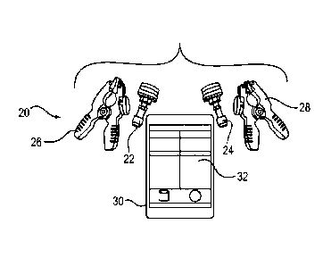
Fig. 4 depicts an exemplary hoseless sensor system 20 for use in sensing
parameters and determining system conditions in a refrigerant unit. In
exemplary embodiments, the sensor system includes a plurality of hoseless
sensors for sensing system parameters of the refrigerant unit, and a portable
electronic device configured to receive the system parameters from the
hoseless
sensors and to calculate system conditions for the refrigerant unit based on
the
system parameters.
Referring to Fig. 4, in the sensor system 20 the plurality of hoseless
sensors may include a hoseless first pressure sensor 22 and a hoseless second
pressure sensor 24. The plurality of hoseless sensors further may include a
hoseless first temperature sensor 26 and a hoseless second temperature sensor
28. The first pressure sensor 22 and first temperature sensor 26 may be
sensors for a high side of the refrigerant system, and the second pressure
sensor 24 and the second temperature sensor 28 may be sensors for the low
side of the refrigerant system. The high side and low side sensors
respectively
may be color coded red and blue as is conventional. A portable electronic
device 30 may calculate system conditions based on sensor parameters
measured by the plurality of hoseless sensors. The portable electronic device
may execute a software program application 32 to calculate system conditions,
including superheat and subcooling for the refrigerant system. The portable
electronic device 30 may be any suitable mobile device, such as, for example,
a
tablet computer, laptop computer, smartphone, or the like. The program
application 32 may be a mobile application suitable for execution by such
portable electronic devices.
7
Date Recue/Date Received 2023-01-13
The use of high side and low side pressure and temperature sensors
permits a variety of system calculations to be performed by the portable
electronic device 30 executing the program application 32. The measurements
may be used to calculate system conditions, such as for example superheat and
subcooling. The program application further may be executed to calculate a
temperature differential (AT) and pressure differential (AP) based on
measurements of the high side sensors relative to the low side sensors. AT and
AP are useful indications of system performance. For example, AT may be
employed as a measure of air coil performance and system capacity. As
another example, a high AP may be indicative of clog in the system, such as
for
example at a filter or coil. AT and AP parameters are useful in a variety of
trouble shooting determinations in evaluating system performance.
Figs. 5 depicts the installation of the hoseless sensor system of Fig. 4
within an air conditioning unit 34. Fig. 6 depicts a close-up view of the
installation of Fig. 5. The sensor system of the present invention eliminates
the
need for hoses to measure system parameters. The pressure sensors 22 and
24 are installed by hand onto the system tube via a flare quick connection,
such
as for example a 1/4" SAE connector or other suitable structure. The
temperature sensors 26 and 28 may be configured as temperature sensor
clamps also installed by hand. The temperature sensor clamps are installed by
clamping on the outside of the refrigerant system tubes next to the pressure
sensors to sense temperature of the refrigerant inside the tubes. The pressure
and temperature sensors may be visually identified with color for low side
(blue)
and high side (red) of the refrigerant system as is conventional.
Fig. 7 is a schematic block diagram depicting operative portions of an
exemplary portable electronic device 30. The portable electronic device 30 may
include a communications interface 36 for wirelessly receiving the system
parameters from the hoseless sensors. The communications interface may also
include a wireless transmitting capability that can transmit information to
the
sensors, such as for example firmware updates or the like, or otherwise
transmit
data externally from the electronic device. The wireless communication may be
8
Date Recue/Date Received 2023-01-13
performed over any suitable wireless interface, such as Bluetooth, Wi-Fi,
cellular
networks, or other suitable wireless technologies that are known in the art.
As
part of such wireless communication and interfacing, the communications
interface 36 may include an auto-connect feature that automatically
establishes
.. a wireless connection for communication with the sensors based on specified
criteria, such as for example range, readiness status or state, and/or other
suitable criteria.
A memory 38, which may be any suitable non-transitory computer
readable medium known in the art, stores the program application 32. The
programming of such applications are known to those skilled in the programming
art, so the precise program code is omitted here for convenience. A processor
device 40 is configured to receive the sensor parameters via the
communications interface 36, and to execute the program application 32 to
calculate the system conditions based on the system parameters. The portable
electronic device 30 further may include a display 42 for displaying pertinent
sensor and system condition information to the technician.
The pressure and temperature sensors transmit pressure and
temperature data to the portable electronic device preferably by a wireless
communication. The executed program application performs a calculation to
display real time system conditions, such as superheat and subcooling. The
portable electronic device and related program application can support
multiple
wireless sensors and sensor types, including for example pressure and
temperature sensors as described above, and additionally sensor types such as,
for example, sensors for humidity, weight, current, vibration, and other
parameters. The program application also allows the user to record and store
the data in the device memory, and may include a graphing feature to aid in
diagnosing the system. It will be appreciated that a variety of communications
technologies may be employed to execute the program application and
cooperate with the sensors. For example, the system may operate via a cellular
network, WiFi network, or other external network. In certain locations,
however,
access to such networks may be limited (e.g., in basements, cellars, subway
9
Date Recue/Date Received 2023-01-13
systems, and other enclosed, underground and remote areas). Accordingly, in
exemplary embodiments the application may run solely over a localized
interface
with all requisite data being stored and processed locally on the portable
electronic device 30.
The program application also may include a GPS feature and a "send"
feature to allow the technician to pin where the job is, and to send the
system
data back to a service shop for analysis. The program application also may
offer
a refrigerant type selection to allow service technicians to use the sensor
system
across multiple different refrigerant systems, along with a calibration
feature to
offset the temperature and pressure display readings. The program application
also permits the technician to save and send system data for further analysis.
The program application also may use location services to inform a technician
of
the closest wholesaler and/or customer service contact information to order
replacement parts for system repair. In this manner, enhanced product support
can be provided.
The hoseless configuration of the present invention has significant
advantages over conventional gauge sets. Because there are no hoses, the
present invention minimizes refrigerant loss and difficulties associated with
processing and reclaiming refrigerant trapped in hoses. The quick connect
coupling of the pressure sensors eliminates the need for the refrigerant blow
off
to empty refrigeration hoses after system inspection. Also, without the need
to
reclaim trapped refrigerant, the hoseless system of the present invention can
be
used for multiple types of refrigerant systems. Relatedly, the invention
eliminates cross contamination between systems by replacing multiple gauge
sets with a sensor system that is useable across different refrigerant systems
with otherwise incompatible refrigerants and oils. The program application
permits the technician to select the proper refrigerant per system for current
usage, and to change the selection for a different type of system.
In addition, because the present invention has a hoseless configuration,
the present invention can be easily carried in a small case or separately. The
overall weight of the hoseless configuration is approximately one fifth as
light as
Date Recue/Date Received 2023-01-13
conventional hose-containing gauge sets. The hoseless configuration,
therefore,
is more readily usable by service technicians when there is a need, for
example,
to climb on ladders and carry tools to service roof-top condensing units for
refrigeration or air conditioners.
The wireless nature of the transmission of the sensor data to the portable
electronic device permits the service technician the flexibility of walking
around
the different parts of the system while reading system conditions displayed on
the portable electronic device with the program application. There is no need
for
the technician to stand next to the gauge set to read pressure, or to utilize
two
technicians with a two-way mobile radio system, as referenced above with
respect to conventional hose gauge sets. The present invention also allows
flexibility for adjusting system components while reading the real time data
through the portable electronic device via the program application. The
increased permissible distance also allows the technician to remove himself of
herself from noise where the measurements are taken, such as for example a
mechanical room in supermarkets where refrigeration compressors are located.
In exemplary embodiments, a repeater or other suitable device may be
employed to extend the range of communication.
In exemplary embodiments, the hoseless sensor system has enhanced
temperature sensors. Each enhanced temperature sensor is configured as a
temperature sensor clamp. In exemplary embodiments, the temperature sensor
clamp includes a clamping portion configured to clamp on a tube of the
refrigerant unit, the clamping portion including a sensor element to measure
temperature about the tube. The clamping portion further includes a plurality
of
clamping teeth, and adjacent clamping teeth interlock in an overlapping
configuration when the clamp closes inward beyond a threshold point. The
clamping portion further includes a perforated gripping portion for gripping
the
tube of the refrigerant unit, the gripping portion including a grating. When
the
clamping portion clamps the tube, the grating scores the tube to clean and
grip
the tube. The temperature sensor clamp further includes a handle and
integrated electronics incorporated into the handle. The integrated
electronics,
11
Date Recue/Date Received 2023-01-13
for example, may include a battery housing for a battery, a light emitting
status
indicator, and/or a wireless interface pair button.
Figs. 8-11 are schematic diagrams depicting various views of an
exemplary temperature sensor clamp 50, including side views with the clamp
open (Figs. 8A-B), side views with the clamp closed (Figs. 9A-B), an isometric
bottom view (Fig. 10), and an isometric top view (Fig. 11.) The temperature
sensor clamp 50 includes a clamping portion 52 constituting the tip of the
temperature sensor clamp, and a handle portion 54. The clamping portion 52
includes an upper clamp tip 56 and a lower clamp tip 58, which respectively
include an upper gripping portion 60 and a lower gripping portion 62. The
upper
gripping portion 62 includes an embedded temperature sensing element 68 for
sensing temperature of a tube in a refrigerant unit. As best seen in Fig. 11
of
this group of figures, the clamping portion further includes a plurality of
clamping
teeth 64, whose operation is described in more detail below. The upper and
lower clamp tips 56 and 58 each may be rotatable about a clamp tip shaft 66,
one each provided in the upper and lower portions of the clamping portion 52.
The handle portion 54 includes an upper handle portion 70 and a lower
handle portion 72. The upper handle portion 70/upper clamp tip 56 are
rotatable
about the lower handle portion 72/tower clamp tip 58 via a center shaft 76. As
further described below, the upper handle portion 70 includes integrated
electronics 78 that are in electrical connection with the temperature sensing
element 68.
As referenced above, Fig. 11 depicts the plurality of clamping teeth 64.
Fig. 12 is a schematic diagram depicting an isometric close-up view of the
clamping portion 52 of the temperature sensor clamp 50, including the clamping
teeth 64 in the closed position. As seen in Figs. 11 and 12, adjacent clamping
teeth interlock in an overlapping configuration when the clamps closes inward.
The interlocking and overlapping nature of the clamp teeth permits an
increased
range of tube size for which the temperature sensor clamp 50 may be employed.
Figs. 13 and 14 are schematic diagrams depicting the operation of the
clamping portion of the temperature sensor clamp for different sized tubes. In
12
Date Recue/Date Received 2023-01-13
particular, Fig. 13 first depicts the operation of the clamping portion to
grip a
relatively large diameter tube 80. As seen in Fig. 13, the clamping portion is
opened to fit the tube diameter, and a relatively wider gripping range may be
achieved by outward rotation of the upper and lower clamping tips 56 and 58
about the clamp tip shafts 66.
As the tube size is reduced, the clamping teeth begin to come together
until the clamp teeth reach a threshold point at which edges of the clamp
teeth
essentially meet. As the clamping teeth close further, adjacent clamping teeth
interlock in an overlapping configuration when the clamps closes inward beyond
the threshold point. Such configuration, for example, is seen in Figs. 11 and
12
in which the clamping portion is fully closed without gripping any tube. In
addition, Fig. 14 depicts the operation of the clamping portion to grip a
relatively
small diameter tube 82. The tube 82 is of a sufficiently small diameter that
the
clamping teeth 64 are closed beyond the threshold point, and thus interlock in
an
overlapping configuration to grip the small-sized tube 82. An enhanced grip
further may be achieved by inward rotation of the upper and lower clamping
tips
56 and 58 about the clamp tip shafts 66.
The enhanced tip configuration of the present invention provides for
gripping an increased range of tube diameters, for example approximately 3/16"
to 1-1/2" diameter tubes, although the tip configuration may be made to
accommodate any suitable diameter tube. Conventional temperature sensor
clamps utilize a flat style jaw that lacks the described interlocking teeth.
The
conventional flat jaw limits the size of tube diameters, for example to
approximately 3/8" to 1-1/8". As a result, the configuration of the clamping
portion of the present invention permits the technician to service white goods
(i.e., small appliances) with small diameter tubes up to large refrigeration
or air
conditioning chillers with large diameter tubes, a range of usage that is not
available with conventional configurations.
The clamping portion of the present invention further includes an
integrated perforated gripping portion for gripping the tube of the
refrigerant unit.
The integrated perforated gripping portion may be configured as a perforated
13
Date Recue/Date Received 2023-01-13
gripping pad to increase the grip of the clamp on the tube. The perforated
gripping portion is seen slightly in the various views. Fig. 15A is a
schematic
diagram depicting an isometric close-up view of the lower clamp tip 58,
including
a perforated gripping pad 84. Oppositely to the perforated gripping pad 84, a
smooth gripping pad 85 is positioned oppositely on the upper clamp tip 56, as
seen in Fig. 15B. As also seen in Fig. 15B, the sensing element 68 is
incorporated into the upper clamp tip within or under the gripping pad 85. The
gripping portion 85 is made smooth (instead of perforated as the gripping pad
84) to provide a better transfer of heat to the sensing element.
lo The pad material for either of the perforated gripping pad 84 or smooth
gripping pad 85 may be, for example, metal, plastic or other similar materials
to
provide a requisite abrasion against a gripped refrigerant tube. Conventional
temperature clamps have smooth or sometimes slightly dimpled pads for
contacting the tube. Conventional smooth or dimpled pads often do not
adequately hold the temperature sensor clamp to the pipe, and the temperature
sensor clamp can slide around or down the tube due to gravity. Such
deficiencies are avoided by the configuration of the described integrated
perforated gripping portion. The gripping portion has a grating configuration
formed by the perforations. When the clamping portion clamps the tube, the
grating scores the tube to pre-clean and better grip the tube.
It is known in the art that an optimal position of the clamping portion is to
grip the refrigerant tube at approximately 4:00/8:00 opposite clock positions
relative to the cross-sectional diameter of the tube. The perforated gripping
portion aids in maintaining this optimal grip position. The clamping portion
also
may include an external marking to aid in aligning at the optimal position, or
the
program application may indicate a proper orientation when installed for
measurement. The proper installation improves the temperature reading by
placing the clamp sensing element in the region where vapor exists inside the
tube. If the clamp is installed at an improper position or allowed to slide
down,
the temperature measurement may be skewed due to oil and/or liquid refrigerant
in that location of the tube.
14
Date Recue/Date Received 2023-01-13
A common practice is to pre-clean the tube with a piece of sandpaper or
similar material, but this adds time to the measurement operation. The present
invention avoids this deficiency. As referenced above, the perforated grating
can
score the tube to pre-clean the outside of the tube prior to taking a
measurement. In typical cases, the tube will be copper; but non-copper tubes
also can be pre-cleaned in this manner. Due to environmental effects, the
copper tubes develop a protective coating naturally called copper oxide. The
tube may also pick up oil and other debris such as dust or dirt, or adhesives
that
will reduce the thermal conductivity, and hence accuracy, of the temperature
sensor clamp. By installing the temperature sensor clamp of the present
invention as described, the technician may spin and rotate the clamp around
the
tube to remove the copper oxide layer and any other contaminants for better
heat transfer prior to taking a measurement. This technique will improve
temperature reading accuracy.
In exemplary embodiments, as referenced above the temperature sensor
clamp further includes integrated electronics, and the integrated electronics
are
incorporated into the handle and are in electrical connection with the sensor
element 68 and a power source. The configuration of the electronics is shown,
for example, in Fig. 10. In addition, Fig. 16 is a schematic diagram depicting
an
isometric close-up view of the upper handle portion of the temperature sensor
clamp, including integrated electronics. In particular, the upper handle
portion 70
includes integrated electronics 78 that are in electrical connection with the
temperature sensing element 68. The integrated electronics may include a
power source housing or cover 90 (see also Fig. 11) housing a power source
such as, for example, a battery or other power supply, a light emitting
indicator
92, and a wireless interface pair button 94. The light emitting indicator may
provide status indications for the temperature sensor clamp, such as for
example
power on/off, ready status, error states, or the like. The wireless interface
pair
button 94 may aid in pairing the temperature sensor clamp for wireless
connection with the portable electronic device 30. The integrated electronics
and
the sensors may be sealed from environmental elements using any suitable
Date Recue/Date Received 2023-01-13
sealing elements. Such sealing may be configured to satisfy any applicable
environmental standards for outdoor use or other specified use conditions.
Fig. 17 is a schematic diagram depicting a side cross-sectional view of an
exemplary hoseless pressure sensor that may be employed as the first pressure
sensor 22 and/or second pressure sensor 24. As seen in Fig. 17, each pressure
sensor includes a pressure sensing element 96 that is threaded into a pressure
sensor housing 98. The threaded engagement, for example, may be provided
by a 1/8" threading. The pressure sensor further may include a flare quick
connection 100, such as for example a 1/4" SAE connector or other suitable
structure, for connection to the refrigerant unit. The pressure sensor further
may
include an integrated charging port 102, which also may be configured as a
1/4"
SAE connector or other suitable structure. The integrated charging port allows
the technician to add or remove refrigerant, or pull a vacuum on the system
without removing the pressure sensor. Such configuration permits the
technician
to monitor real time conditions as the refrigerant is added or removed.
In accordance with the above description, an aspect of the invention is a
sensor system for a refrigerant. In exemplary embodiments, the sensor system
includes a plurality of hoseless sensors for sensing system parameters of the
refrigerant unit, and a portable electronic device configured to receive the
system
parameters from the hoseless sensors and to calculate system conditions for
the
refrigerant based on the system parameters.
In an exemplary embodiment of the sensor system, the plurality of
hoseless sensors comprises a hoseless first pressure sensor and a hoseless
second pressure sensor, and a hoseless first temperature sensor and a hoseless
second temperature sensor.
In an exemplary embodiment of the sensor system, the first pressure
sensor and first temperature sensor are sensors for a high side of the
refrigerant
system, the second pressure sensor and the second temperature sensor are
sensors for the low side of the refrigerant system, and the system conditions
calculated by the portable electronic device comprise superheat and subcooling
for the refrigerant system.
16
Date Recue/Date Received 2023-01-13
In an exemplary embodiment of the sensor system, the first and second
temperature sensors each comprises a temperature sensor clamp having a
clamping portion configured to clamp on a tube of the refrigerant unit, the
clamping portion including a sensor element to measure temperature about the
tube.
In an exemplary embodiment of the sensor system, the clamping portion
of each temperature sensor clamp includes a plurality of clamping teeth, and
adjacent clamping teeth interlock in an overlapping configuration when the
clamps closes inward beyond a threshold point.
In an exemplary embodiment of the sensor system, the clamping portion
of each temperature sensor clamp includes a perforated gripping portion for
gripping the tube of the refrigerant unit.
In an exemplary embodiment of the sensor system, the gripping portion
comprises a grating, wherein when the clamping portion clamps the tube, the
grating scores the tube to clean and grip the tube.
In an exemplary embodiment of the sensor system, each temperature
sensor clamp further comprises a handle and integrated electronics, and the
integrated electronics are incorporated into the handle and in electrical
connection with the sensor element.
In an exemplary embodiment of the sensor system, the integrated
electronics include at least one of a power source, a light emitting
indicator, and
a wireless interface pair button.
In an exemplary embodiment of the sensor system, the integrated
electronics and the sensors are sealed from environmental elements.
In an exemplary embodiment of the sensor system, each of the first and
second pressure sensors comprises a hoseless flare quick connection for
connecting the pressure sensors to the refrigerant unit.
In an exemplary embodiment of the sensor system, the first and second
pressure sensors further comprise an integrated charging port.
17
Date Recue/Date Received 2023-01-13
In an exemplary embodiment of the sensor system, the portable electronic
device is configured to receive the system parameters from the hoseless
sensors over a wireless interface.
In an exemplary embodiment of the sensor system, the portable electronic
device includes a communications interface for wirelessly receiving the system
parameters from the hoseless sensors, a memory storing a program application
for calculating system conditions, and a processor device configured to
receive
the sensor parameters via the communications interface, and to execute the
program application to calculate the system conditions based on the system
parameters.
Another aspect of the invention is a temperature sensor clamp for sensing
temperature in a refrigerant unit. In exemplary embodiments, the temperature
sensor clamp includes a clamping portion configured to clamp on a tube of the
refrigerant unit, the clamping portion including a sensor element to measure
temperature about the tube, and the clamping portion includes a plurality of
clamping teeth, and adjacent clamping teeth interlock in an overlapping
configuration when the clamp closes inward beyond a threshold point.
In an exemplary embodiment of the temperature sensor clamp, the
clamping portion includes a perforated gripping portion for gripping the tube
of
the refrigerant unit.
In an exemplary embodiment of the temperature sensor clamp, the
gripping portion comprises a grating, wherein when the clamping portion clamps
the tube, the grating scores the tube to clean and grip the tube.
In an exemplary embodiment of the temperature sensor clamp, the
temperature sensor clamp further comprises a handle and integrated
electronics,
and the integrated electronics are incorporated into the handle and in
electrical
connection with the sensor element.
In an exemplary embodiment of the temperature sensor clamp, the
integrated electronics include at least one of a battery, a light emitting
indicator,
and a wireless interface pair button.
18
Date Recue/Date Received 2023-01-13
Although the invention has been shown and described with respect to
certain preferred embodiments, it is understood that equivalents and
modifications will occur to others skilled in the art upon the reading and
understanding of the specification. The present invention includes all such
equivalents and modifications, and is limited only by the scope of the
following
claims.
19
Date Recue/Date Received 2023-01-13