Note: Descriptions are shown in the official language in which they were submitted.
CA 03186754 2022-11-18
WO 2021/234615
PCT/IB2021/054360
DEVICE FOR CHECKING THE POSITION OF AN ACTUATOR
DESCRIPTION
Technical field of the invention
The present invention relates to a device for checking the position
of a mechanical element in translational or rotational motion. In particular,
the device is suitable for controlling the position of an actuator, preferably
a linear pneumatic actuator.
In general, controlling a generic system is equivalent to imposing a
desired behavior on it. More specifically, this consists in defining a
controller capable of processing the information coming from a feedback
signal, generated by a transducer. All this can be summarized with the
.. definition of a closed loop control system, used for different applications
in different sectors, especially in those related to the automation field.
In order to build a closed control loop, it is of fundamental
importance to choose the variable to be controlled, which is closely
connected with the feedback signal and therefore also with the sensor
.. which has the task of generating the feedback signal.
In order to control the motion of a mechanical element, it is usual to
develop a positioning system, based on a controller capable of processing
information relating to the instantaneous position of the element itself.
Hence the need to develop a device suitable for controlling a position,
including but not being limited to, a suitable position sensor.
1
CA 03186754 2022-11-18
WO 2021/234615
PCT/IB2021/054360
Background art
As it is known, in the automation field the position sensors can be
divided in different macro-categories, for example according to the type
or according to the coupling with the mechanical element.
According to the type, incremental or absolute position sensors can
be distinguished. The first ones, being devoid of an intrinsic reference,
must carry out a calibration procedure at each start-up in order to reassign
the zero reference. The second ones, on the other hand, once the initial
calibration has been carried out, are always capable to detect the correct
measurement, without repeating each time the procedure from the
beginning.
On the basis of the coupling with the mechanical element, contact
sensors or non-contacting or "contactless" sensors are defined according
to the most common Anglo-Saxon terminology. Contact sensors, such as
potentiometers, usually use a mechanism coupled with the mechanical
system to carry out the measurement, while contactless sensors, such as
optical encoders or magnetic transducers, do not provide for direct contact
between the moving parts and therefore have to resort to more complex
technologies. Contactless sensors, however, have a considerable
advantage from a mechanical point of view: the absence of contact
between the moving parts leads to an absence of component wear,
therefore to an useful life if not infinite, certainly longer than that of the
contact sensors.
The present invention takes as an example of implementation a non-
contacting magnetic sensor and therefore it concentrates in the following
2
CA 03186754 2022-11-18
WO 2021/234615
PCT/IB2021/054360
on contactless magnetic sensors, which, in order to extrapolate the
necessary information, must be able to communicate with a component
capable of generating a magnetic field. A magnetic field /4, in general,
can be schematized as a vector field. As such, it can be represented with
the field lines, which are tangent in each of their points to individual
carriers g, each of which is decomposable into three main Cartesian
components Fix, By, gz, defined by a reference Cartesian tern,
conventionally allocated by the orientation of the position sensor. The
measured variable is therefore the relative position between the sensor
and the magnetic component. In order to measure its relative position,
one of the two elements (it does not matter which of the two) must be
suitably fixed, so as to identify the reference for the component in motion.
The first limitations, during the design phase, are assigned by the
specific sector in which they must operate. In the case of this patent, one
wants to investigate a position sensor aimed at the automation of a
pneumatic positioning system, consisting of a positioning means which
has the task of moving a linear actuator. However, the idea is to find a
solution that can also be adapted to other sectors and other applications.
In particular, the primary aim is to obtain an suitable solution for the
evaluation of the position of both a translating and rotating mechanical
system.
As it is also known, in the specific field of pneumatic automation, the
development of a sensor encounters significant drawbacks: often the
dynamics of the mechanical system to be controlled is high and the
constraints to be observed in the development phase are many.
3
CA 03186754 2022-11-18
WO 2021/234615
PCT/IB2021/054360
A main technical problem consists in that the control of the
mechanical system is operated with a current signal which varies between
4mA to 20mA. Therefore, necessarily, in order to manage the power
supply of all the electrical components, a current value of less than 4mA
must be used. This implies that the energy consumption of the sensor
used must be sufficiently low, commensurate with that of the other
elements used. It may therefore be useful to install a sensor capable of
activating only in the event of an actual request for use, a remaining shut-
off for the rest of the time. If this represents an advantage from the
consumption point of view, on the other hand it implies a second technical
problem: it is mandatory, in fact, to adopt an absolute position sensor,
since, when using an incremental position sensor, the calibration should
be made at each ignition, so consequently losing its previously defined
reference. In addition, a third technical problem consists in that in order
to cope with high mechanical performances, also the sensor must ensure
a similar dynamic response, while respecting the constraints outlined in
above.
Finally, a magnetic contactless sensor, used for a pneumatic
positioning system, must solve a further technical problem linked to the
non-linearity of the measurement. This entails an additional limitation,
linked to the maximum stroke deductible from the sensor, which directly
affects the maximum stroke of the actuator.
An example of this technology is described in US690928182. In
particular, the document describes a Hall effect sensor which measures
the intensity of the magnetic field, generated by a bar designed ad hoc
4
CA 03186754 2022-11-18
WO 2021/234615
PCT/IB2021/054360
and located in the point where the sensor is located, with the aid of a
concentrator. The shape of the field is particular and is designed to set up
a linear relationship between the position of the mechanical system and
the intensity of the field itself. The limit of the solution described in the
prior document is inherent in the impossibility of managing long strokes,
due to the small variation of the gradient of the magnetic field, which
involves important non-linearities in the measurement performed.
There is therefore the need to define a device for controlling the
position of a mechanical element in a translational or rotational motion
and, more particularly, a device for checking the position of an actuator,
that is free from the drawbacks mentioned above.
Summary of the invention
One aim of the present invention is therefore the definition of a
device for checking the position of a mechanic element in translational or
rotational motion which performs a predetermined stroke and, in
particular, a device for checking the position of an actuator, preferably,
but not necessarily, a linear pneumatic actuator. The device must be able
to handle long strokes of the actuator and in any case must be devoid of
the drawbacks relating to applications according to the known art.
Still more in particular, the control device object of the present
invention may comprise a magnetic contactless sensor, as described
according to the teachings of the prior art.
More in general, the device comprises two necessary elements: one
component capable of generating a particular shape of magnetic field and
a sensor sensitive to the field itself.
5
CA 03186754 2022-11-18
WO 2021/234615
PCT/IB2021/054360
The magnetic component has a helical shape, being able to be, for
example, either a flexible magnetic element of helical shape or a non-
magnetic linear bar in which a plurality of magnetic elements arranged
with a helical shape are inserted. Ultimately, whatever the solution chosen
for the magnetic component, it must be able to generate a very precise
field shape.
The sensor, which is not in itself part of the present invention but is
in combination with the magnetic component, is based on a technology
that integrates the action of several distinct Hall effect sensors, preferably
compacted into a single electronic board, in such a way as to be able to
measure the value of the magnetic field in different directions. Therefore,
the sensor does not directly return the instantaneous position of the
mechanical system, but instead the magnetic field strength values
according to the different directions identified by the individual Hall effect
sensors.
For this reason, it was necessary to develop also a methodology for
decoding and processing the signals coming from the various Hall effect
sensors. This was achieved in the form of a specific decoding algorithm
capable of processing the data emitted by the sensor, finally extrapolating
the desired variable, that is the position of the mechanical system of
interest.
Alternatively, other types of sensors sensible to the magnetic field
can also be used, such as MEMS sensors or magneto-resistive sensors,
always maintaining the same decoding algorithm and paying particular
6
CA 03186754 2022-11-18
WO 2021/234615
PCT/IB2021/054360
attention to the compliance with the performance and electronic
constraints introduced above.
One of the main advantages is that, by extrapolating the field
strength value over multiple defined directions, it is possible to use a
single sensor capable of measuring both linear and angular displacements.
According to a first aim of the present invention, therefore, a device
is described for checking the position of a mechanical element in a
translational and rotational motion, which performs a predetermined
stroke and has the characteristics set out in the attached independent
claim of the device.
According to a further aim of the present invention, a method for
decoding a position signal is described, having the characteristics set out
in the attached independent claim of the method.
Additional embodiments of the above-mentioned plant, which are
preferred and/or particularly advantageous, are described according to
the characteristics set forth in the attached dependent claims.
Brief description of the drawings
The invention will now be described with reference to the attached
drawings, which illustrate some non-limiting examples of embodiment, in
which:
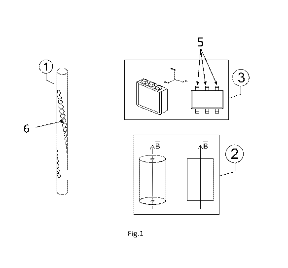
- figure 1 shows the schematic drawings of the individual components of
the device for checking the position, according to one embodiment of
the present invention,
- figure 2 is an assembly diagram of the magnetic component of Fig. 1,
and
7
CA 03186754 2022-11-18
WO 2021/234615
PCT/IB2021/054360
- figure 3 is a schematic representation of the final solution of the device
of Fig. 1.
Detailed description
Referring now to the above figures, hereinafter a device 10 is
described for checking the position of a mechanical element in a
translational or rotational motion. The device comprises a magnetic
component 4 integral with the mechanical element the position of which
is to be determined and a stationary magnetic sensor 3.
The magnetic component 4 must be able to generate a particular
field shape. In order to obtain such result one possible solution is that the
magnetic component 4 comprises a bar 1 of non-magnetic material, for
example aluminum, provided with a plurality of holes 6 and in said
plurality of holes 6 a plurality of magnetic cylinders 2 is fixed with
interference (glued or embedded), one cylinder 2 for each hole 6, wherein
.. the cylinders 2 are polarized according to same direction, identified by
the
field vector B.
The individual magnetic cylinders 2 are arranged along the non-
magnetic bar 1 following a helical pattern. The number and arrangement
of the magnetic cylinders along the helix are determined so as to obtain
an angular displacement of the magnetic field between the end magnetic
cylinders 2, 2", equal to an angle sufficiently large to ensure an efficient
interpretation of the values, for example an angle between 90 and 270
(in the figure, it must be noted, for example, that the referred angle is
approximately flat). As the angular displacement and the distance
.. between consecutive magnetic cylinders can be imposed at will, the length
8
CA 03186754 2022-11-18
WO 2021/234615
PCT/IB2021/054360
of the non-magnetic bar 1 is also imposed and, therefore, it can be
proportional to the stroke of the actuator.
Therefore, it can be said that, with this technology, there is no
measurable maximum stroke limit. For this reason, it is possible to
develop different non-magnetic bars, always provided with a helix of
magnetic cylinders and which have a different length, depending on the
stroke to be actually measured.
As an alternative to this solution, the magnetic component can have
a different design, as long as it is able to replicate the same shape of the
magnetic field. An example could be to use a flexible material with high
magnetic properties, with which to replicate the helical shape given by the
arrangement of the magnetic cylinders in the case previously illustrated.
Otherwise, according to a further example, the magnetic component can
be devoid of the non-magnetic bar and comprise a plurality of small
prismatic-shaped magnets, arranged with an angle of phase shift between
them, in such a way as to reconstruct, also in this case, a helical profile.
The sensor 3 sensitive to the magnetic field, suitably constrained,
must be chosen so that it can detect the field simultaneously on several
conventionally defined directions. Advantageously, a solution is
represented by a three-dimensional magnetic sensor 3, which contains
inside it three distinct Hall effect sensors 5, arranged orthogonally to each
other to form a reference Cartesian triad and compacted in a single
electronic board. This allows to obtain the intensity of the magnetic field
on the three axes defined by the reference triad, given by the orientation
of the individual Hall effect sensors 5, strictly connected to the spatial
9
CA 03186754 2022-11-18
WO 2021/234615
PCT/IB2021/054360
orientation of the sensor itself. Therefore, the sensor 3 does not directly
return a position value, but the three field components gx, B, gz on the
three axes of the triad. Therefore, the same results can also be obtained
with sensors of different types capable of returning the intensity of the
field in several directions. A schematic drawing of the device as a whole is
shown in figure 3.
The extrapolation of the value of the instantaneous position of the
mechanical element is obtained thanks to a specific method based on a
decoding algorithm. The aim of the method is to associate the quantities
related to the magnetic field with the relative position between the sensor
and the magnetic component. Ultimately the method includes the
following steps of:
- detecting one or more quantities linked to the generated magnetic
field;
- correlating the position of the mechanical element to the quantities
linked to the magnetic field.
In order to do this, two different approaches have been developed.
The first one is based on the analysis of the trend of the lines of force of
the magnetic field. This is equivalent to quantifying the slope of the lines
of force, an operation which coincides with the calculation of the angle of
inclination, point by point, of the individual field vectors B tangentially to
the lines of force themselves. In order to avoid complex considerations
with solid angles, it is necessary to determine the trend of the lines of
force projected on a Cartesian reference plane, chosen on the basis of the
geometry of the field and the relative orientation between sensor and
CA 03186754 2022-11-18
WO 2021/234615
PCT/IB2021/054360
magnetic component. This means that, by selecting two components of
the field corresponding to the Cartesian reference plane still previously
chosen, it is theoretically possible, by exploiting the arctangent and
modifying its trend with a scale factor k set by the user, to determine a
mathematical function which expresses the trend of the slope of the lines
of force in relation to the position. Supposing, for example, to choose the
XY plane as the Cartesian reference plane, then using the components gx
and gy, extrapolated from the sensor, it is possible to calculate:
By
19xy = arctan H or Dyx = arctan
k-By k-Bx
The advantage is that, considering the magnetic field generated by
the helix bar, the mathematical function in question is monotonous and
easily interpolated with a straight line. Therefore, once the equation of the
interpolating straight line has been obtained, a linear relationship will be
available between the position of the mechanical system and the slope of
the lines of force. Therefore, by exploiting the inverse formulas, it is
possible to return to the target variable (position of the mechanical
element) from the Cartesian components of the magnetic field. In this
way, the problem of the non-linearity is drastically reduced, as linear
curves are considered. Furthermore, thanks to the optimum repeatability
of the measurement, it can be sure that the same position value will
always correspond to each slope value.
By using a magneto-resistive sensor, which measures the total
intensity of the magnetic field and its angle of inclination, it is possible
to
reach the same conclusions, without resorting to the calculation of the
angle with the arctangent function,
CA 03186754 2022-11-18
WO 2021/234615
PCT/IB2021/054360
The second approach of the decoding algorithm instead exploits all
three Cartesian components gx, gy, B. In fact, it can be observed how,
in no point of the space, gx, gy, gz be repeated, by assuming the same
values. In other words, by moving the sensor 3 in any direction with
respect to the magnetic component 4, although remaining in any case at
a distance such as to obtain suitable values from the measurement,
ternary values gx, gy, gz are always obtained, which are different from
each other. This constitutes a considerable advantage, as thanks to an
appropriately defined lock-up table or by referring to a mathematical
function capable of determining the exact value of the components of the
field at each point, it is possible to define the correct relative position
between sensor and magnetic bar. Furthermore, by exploiting this
algorithm, as the exact value of the field is known in any point of the
space, it is possible to discriminate the presence of small displacements
or vibrations, the presence of which is inevitable in a real case, by
extrapolating only the exact position of the mechanical system, only in the
direction of the motion to be detected. This is particularly useful when the
system is able to act and control only one axis, but small movements
occur outside the control, even in the other directions.
In addition to the embodiments of the invention, as described above,
it is to be understood that numerous further variants exist. It must also
be understood that said embodiments are only exemplary and do not limit
neither the aim of the invention, nor its applications, nor its possible
configurations. On the contrary, although the above description makes it
possible for the skilled person to implement the present invention at least
12
CA 03186754 2022-11-18
WO 2021/234615
PCT/IB2021/054360
according to an exemplary configuration thereof, it must be understood
that numerous variations of the components described are conceivable,
without thereby departing from the object of the invention, as defined in
the attached claims.
13