Note: Descriptions are shown in the official language in which they were submitted.
WO 2022/031853
PCT/US2021/044550
EXTENDABLE DRAWER SLIDE
BACKGROUND OF THE INVENTION
[0001] The present invention relates generally to drawer slides, and
more particularly to a
drawer slide with installation and rail removal features.
[0002] Drawer slides are commonly used to extendably mount trays, drawers, and
casings in a
structure, for example trays or drawers in a cabinet or other frame. The use
of drawer slides often
allows for compact storage of the trays or drawers, while providing relative
ease of user access to
items in the trays or drawers when desired.
[0003] Unfortunately, at times installation of the drawer slides may pose
difficulties. Drawer
slides may often be used in a pair for any particular tray or drawer, and to
increase smoothness of
operation it may be preferable that the pair of drawer slides be similarly
aligned. Installation with
such alignment may take some care, and may be made more difficult if the pair
of drawer slides
is desired to have an alignment different than that of the cabinet or frame in
which they are
installed.
[0004] For some drawer slides, there may be reasons to allow for disassembly
of some of their
constituent parts. For example, a drawer slide may include multiple rails,
with each rail
extendable from another. Separation of the rails may therefore be desirable at
particular times,
for a variety of reasons. However, during normal operation of extension and
retraction of a
drawer, separation of the rails of the drawer slide may be highly undesirable.
BRIEF SUMMARY OF THE INVENTION
[0005] Some embodiments provide a drawer slide comprising a plurality of
extendably
coupled rails, including a first rail, for mounting to a cabinet, that
includes at least one opening
1
CA 03187224 2023- 1- 25
WO 2022/031853
PCT/US2021/044550
for receiving a fastener to support the rail with respect to the cabinet at a
non-zero angle with
respect to a base of the cabinet and for viewing a potential support position
at a zero angle with
respect to the base of the cabinet. In some embodiments the opening includes a
plurality of
support surfaces for engagement with the fastener, each support surface
providing for placement
of the fastener at a different position with respect to the rail.
[0006] Some embodiments provide a drawer slide comprising a plurality of
extendably
coupled rails, including a first rail for mounting to a cabinet, the first
rail including a longitudinal
web defining a first plane, with offset portions within the web extending
outward from the first
plane, at least some of the offset portions each including at least one
aperture for receiving a
fastener for fastening the rail to the cabinet. In some embodiments the offset
portions extend
from the first plane in a direction away from other rails of the drawer slide.
In some
embodiments a forward edge of the web includes an offset portion along an
entire length of the
forward edge of the web. In some embodiments the web is circumferentially
bounded by offset
portions. In some embodiments the offset portions circumferentially bounding
the web extend a
same distance from the first plane in a direction away from other rails of the
drawer slide. In
some embodiments a portion of a structure providing a raceway of the first
rail is part of the
offset portion of the forward edge of the web. In some embodiments a portion
of a structure
providing a raceway of the first rail is part of the offset portion
circumferentially bounding the
web.
[0007] Some embodiments provide a drawer slide comprising a first rail, a
second rail
extendably coupled to the first rail, a disconnect lever mounted on forward
portion of first rail for
constraining movement of the second rail in at least one direction, and a stop
tab on the first rail
for engaging a catch on the second rail to stop forward translation of second
rail, with the
2
CA 03187224 2023- 1- 25
WO 2022/031853
PCT/US2021/044550
disconnect lever movable to permit the second rail to be moved in the at least
one direction to
allow the catch to pass by the stop tab. In some embodiments the disconnect
lever is movable in
both a rotatable and translatable manner. In some embodiments the disconnect
lever is
translatable between a first position and a second position. In some
embodiments the disconnect
lever is not rotatable in the first position, but is rotatable in the second
position. In some
embodiments rotation of the disconnect lever when in the second position
permits the second rail
to be moved in the at least one direction to allow the catch to pass by the
stop tab. In some
embodiments another rail includes a feature to rotate the disconnect lever,
from a position
permitting the second rail to be moved in the at least one direction to a
position not permitting
the second rail to be moved in the at least one direction, during or at
conclusion of relative
retraction of the first rail and the other rail. In some embodiments the other
rail is the second rail.
In some embodiments another rail includes a feature to translate the
disconnect lever from the
second position to the first position during or at conclusion of relative
retraction of the first rail
and the other rail. In some embodiments the feature is an in-stop of the
second rail. In some
embodiments the second rail includes an in-stop positioned to contact the
disconnect lever on
closing of the slide and translate the disconnect lever from the second
position to the first
position. In some embodiments the in-stop is positioned to contact the
disconnect lever on
closing of the slide and rotate the disconnect lever from a position
permitting the second rail to
be moved in the at least one direction to a position constraining movement of
the second rail in
the at least one direction. In some embodiments the in-stop comprises an
upturned portion of the
upper raceway of the second rail.
[00081 Some embodiments provide a drawer slide comprising a first rail, an
intrusion in a
raceway of the first rail, a second rail extendably coupled to the first rail,
a moveable hook
3
CA 03187224 2023- 1- 25
WO 2022/031853
PCT/US2021/044550
mounted to the second rail, with a bend of the hook extending past a surface
of a raceway of the
second rail sufficiently far such that the intrusion in the raceway of the
first rail is in a travel path
of at least part of the hook with the hook in a first position, and out of the
travel path of the hook
with the hook moved to a second position.
[0009] These and other aspects of the invention are more fully comprehended
upon review of
this disclosure.
BRIEF DESCRIPTION OF THE FIGURES
[0010] FIG. 1 A is a perspective rear inner side view of a drawer slide in
accordance with
aspects of the invention in a closed or unextended position.
[0011] FIG. 1B is a perspective rear inner side view of a further drawer slide
in accordance
with aspects of the invention in a closed or unextended position.
[0012] FIG. 2A is a perspective rear inner side view of the drawer
slide of FIG. lA in an open
or extended position.
[0013] FIG. 2B is a perspective rear inner side view of the further drawer
slide of FIG. 1B in
an open or extended position.
[0014] FIG. 3A is a perspective front outer side view of the drawer slide of
FIG. lA in an
open or extended position.
[0015] FIG. 3B is a perspective front outer side view of the further drawer
slide of FIG. 1B in
an open or extended position.
[0016] FIG. 4A is a perspective front outer side view of the drawer slide of
FIG. lA in a
closed or unextended position.
[0017] FIG. 4B is a perspective front outer side view of the further drawer
slide of FIG. 1B in
a closed or unextended position.
4
CA 03187224 2023- 1- 25
WO 2022/031853
PCT/US2021/044550
[0018] FIG. 5A is an inner side view of the outer rail of the drawer slide of
FIG. 1A, in
accordance with aspects of the invention.
[0019] FIG. 5B is a close-up view of a portion of the outer rail of FIG. 5A,
with the portion
including a front opening for receiving a fastener to support the outer rail
with respect to a
cabinet.
[0020] FIG. 5C is an inner side view of the outer rail of the further drawer
slide of FIG. 1B, in
accordance with aspects of the invention.
[0021] FIG. 5D is a close-up view of a portion of the outer rail of FIG. 5B,
with the portion
including mounting holes for receiving a fastener to support the outer rail
with respect to a
cabinet.
[0022] FIG. 6A is a partially transparent view of portions of an inner rail
and an intermediate
rail of the drawer slide of FIG. 1A, and a disconnect lever for constraining
in-plane movement of
the inner rail, in accordance with aspects of the invention.
[0023] FIG. 6B is a partially transparent view of portions of an inner rail
and an intermediate
rail of the further drawer slide of FIG. 1B, and a disconnect lever for
constraining in-plane
movement of the inner rail, in accordance with aspects of the invention.
[0024] FIG. 7 is a cut-away perspective view of the inner rail and
intermediate rail of FIG. 6A,
showing an example of a catch and stop tab for stopping forward movement of
the inner rail with
respect to the intermediate rail, in accordance with aspects of the invention.
[0025] FIG. SA is an inner side view of the drawer slide of FIG. 1A, with the
disconnect lever
constraining upward vertical movement of the inner rail with respect to the
intermediate rail,
such that the catch may not pass by the stop tab.
5
CA 03187224 2023- 1- 25
WO 2022/031853
PCT/US2021/044550
[0026] FIG. 8B is an inner side view of the further drawer slide of FIG. 1B,
with the
disconnect lever constraining upward vertical movement of the inner rail with
respect to the
intermediate rail, such that the catch may not pass by the stop tab.
[0027] FIG. 9A is a further inner side view of the drawer slide of FIG. 1A,
with the disconnect
lever moved to a position such that the catch may pass by the stop tab.
[0028] FIG. 9B is a further inner side view of the further drawer slide of
FIG. 1B, with the
disconnect lever moved to a position such that the catch may pass by the stop
tab.
[0029] FIG. 10 is a perspective view of an intrusion in a raceway of a first
rail and a hook
mountable to a second rail, with the intrusion in a travel path of a portion
of the hook.
[0030] FIG. 11 is a perspective view of the drawer slide of FIG. 1A with the
hook of FIG. 10
mounted to an intermediate rail, with the hook moved to a position such that
an intrusion in a
raceway of the outer rail is not in the travel path of the hook.
[0031] FIG. 12A is a close-up perspective view of the drawer slide with hook
of FIG. 11, with
the hook moved to a position such that the intrusion is not in the travel path
of the hook.
[0032] FIG. 12B is a close-up perspective view of the further drawer slide of
FIG. 1B, with an
alternate hook block mounted to an intermediate rail, with a hook of the hook
block moved to a
position such that an intrusion in a raceway of the outer rail is not in the
travel path of the hook.
[0033] FIG. 13 is a perspective rear inner side view of a yet further drawer
slide in accordance
with aspects of the invention in an open or extended position.
[0034] FIG. 14 is a front view of the yet further drawer slide of FIG. 13.
DETAILED DESCRIPTION
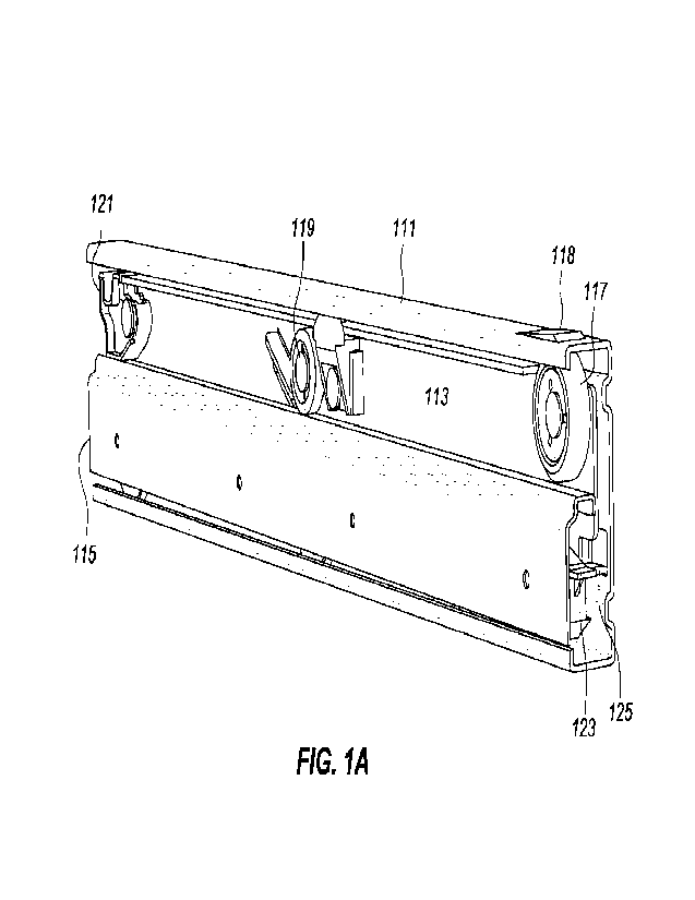
[0035] FIG. lA is a perspective rear inner side view of a drawer
slide in accordance with
aspects of the invention in a closed or unextended position. The drawer slide
of FIG. 1A is a
6
CA 03187224 2023- 1- 25
WO 2022/031853
PCT/US2021/044550
three rail drawer slide, having an outer rail 111, an intermediate rail 113,
and an inner rail 115. In
some embodiments the drawer slide may be a two rail drawer slide, for example
having an outer
rail and an inner rail. The outer rail has a lengthwise longitudinal web,
bounded longitudinally by
opposing raceways. The intermediate rail is nested within the raceways of the
outer rail, with the
intermediate rail longitudinally extendable from the outer rail. The inner
rail is longitudinally
extendably coupled to the outer rail. In many embodiments the outer rail is
mounted to an
interior of a cabinet, with the inner rail mounted to a drawer or tray.
Extension of the
intermediate and inner rails withdraws the drawer or tray from the cabinet, at
least partially,
allowing for access to contents of the drawer or tray.
[0036] FIG. lA also shows a rear upper roller 117 and a mid-rail roller 119.
The rear upper
roller is mounted to a rear of a longitudinal web of the intermediate rail,
and is in rolling contact
with an upper raceway of the outer rail, and, with the drawer slide in the
closed position, an
outside of an upper raceway of the inner rail. In some embodiments, and as
shown in FIG. 1A,
the upper raceway of the outer rail includes a partially punched out outwardly
extending basin
118. The basin may receive the rear upper roller with the slide in the closed
position, providing
for example a detent with the drawer slide in the closed position, assisting
the slide in
maintaining the closed position. The mid-rail roller is also mounted to the
longitudinal web of
the intermediate rail, approximately mid-way along its longitudinal length.
The mid-rail roller is
in rolling contact with the upper raceway of the inner rail.
[0037] In some embodiments, and as shown in FIG. 1A, the drawer slide includes
a forward
disconnect lever 121 and/or a rear hook block 123. The forward disconnect
lever is shown
mounted to a front of the longitudinal web of the intermediate rail. The
disconnect lever is in
contact with an outer surface of the upper raceway of the inner rail, or close
to contact with that
7
CA 03187224 2023- 1- 25
WO 2022/031853
PCT/US2021/044550
outer surface in some embodiments. In the embodiment of FIG. 1A, a forward
portion of the
disconnect lever extends forward of a forward end of the upper raceway of the
intermediate rail.
In operation, the disconnect lever prevents a portion of the inner rail under
the disconnect lever
from being raised vertically with respect to the intermediate rail, or, more
generally, being
displaced, in one direction, in a plane parallel to the webs of the rails of
the drawer slide.
[0038] The rear hook block 123 is shown in FIG. lA as nested alongside the web
of the inner
rail, alongside the web of the intermediate rail. As will be discussed later,
the hook block is
mounted to the intermediate rail. In operation, a hook of the hook block
engages a forward stop
in the lower raceway of the outer rail to set an extent of extension of the
intermediate slide from
the outer rail. In FIG. 1A, a rearward extending tab of the hook block is
visible. In some
embodiments the tab may be used to lift the hook, allowing the hook to bypass
the forward stop,
such that the intermediate rail may be completely withdrawn from the outer
rail.
[0039] FIG. lA also shows a stop tab 125 extending from a rear of the web of
the outer rail
and towards the web of the inner rail. The stop tab may, for example, be
lanced or formed from
the web of the outer rail. The stop tab is in the travel path of the web of
the intermediate rail
and/or, in some embodiments, the rear hook block. The stop tab serves as a
rear stop for motion
of the intermediate rail.
[0040] FIG. 1B is a perspective rear inner side view of a further drawer slide
in accordance
with aspects of the invention in a closed or unextended position. The further
drawer slide of FIG.
1B is similar to the drawer slide of FIG. 1A. Compared to the drawer slide of
FIG. 1A, the
drawer slide of FIG. 1B has an intermediate rail 113b of greater height than
the intermediate rail
of the slide of FIG. 1A, and an outer rail 111b also of greater height than
the outer rail of the
slide of FIG. 1A. The inner rail 115 of the drawer slide of FIG. 1B, however,
is substantially the
8
CA 03187224 2023- 1- 25
WO 2022/031853
PCT/US2021/044550
same as that of FIG. 1A. With the inner rail rollably mounted about a bottom
of the intermediate
rail, there is a greater distance separating a top of the inner rail and a top
of the intermediate and
outer rails for the drawer slide of MG 1B than for the drawer slide of FIG.
1A. To account for
that difference, at least in part, in some embodiments the inner member
disconnect lever 121b of
the drawer slide of FIG. 1B is differently shaped than that of the drawer
slide of FIG. 1A.
[0041] In addition, the drawer slide of FIG. 1B includes a V-shaped rear stop
125b at a rear
end of the web of the outer rail, in place of the stop tab 125 of the drawer
slide of MG. 1A. The
V-shaped rear stop is formed out of a lower rear edge of the web of the outer
rail, in a horizontal
V-shape. The horizontal V-shape has ends of the V-shape coupled to the web and
sides of the V-
shape angling toward each other, with a point of the V extending towards a web
of the inner rail.
The V extends into the travel path of the web of the intermediate rail, with
the V serving as a rear
stop for travel of the intermediate rail. Compared to the stop tab of the
drawer slide of FIG. 1A,
the V-shaped stop of the drawer slide of FIG. 1B is believed to be able to
withstand greater
impact forces in stopping travel of the intermediate rail as the drawer slide
closes.
[0042] FIG. 2A is a perspective rear inner side view of the drawer slide of
FIG. 1A in an open
or extended position. In the open position, the intermediate rail 113 is
longitudinally extended
from the outer rail 111, and the inner rail 115 is longitudinally extended
from the intermediate
rail. For the embodiment of FIG. 1A, approximately half of the intermediate
rail extends forward
from the outer rail, and approximately half of the inner rail extends forward
from the
intermediate rail.
[0043] As may be seen in FIG. 2A, the outer rail includes a longitudinal web
211, bounded by
opposing inward facing raceways 213a.b along longitudinal edges of the
longitudinal web. The
upper rear roller 117 mounted to the web of the intermediate rail is in
rolling contact with the
9
CA 03187224 2023- 1- 25
WO 2022/031853
PCT/US2021/044550
upper raceway 213a of the outer rail. Similarly, lower rollers 215a-c of the
intermediate rail are
positioned to be in rolling contact with the lower raceway 213b of the outer
rail and in rolling
contact with the upper raceway 219 of the inner rail. The lower rollers are
positioned spread
along the length of the intermediate rail; depending on extent of extension,
different ones of the
lower rollers may be in contact with both the lower raceway of the outer rail
and the upper
raceway of the inner rail, or only one of them, or, at times that may be
often, none of them. For
example, in FIG. 2A, a leading lower roller 215a is only in contact with the
upper raceway of the
inner rail, a mid-lower roller 215b is on contact with both the upper raceway
of the inner rail and
the lower raceway of the outer rail, and a lagging lower roller 215c is only
in contact with the
lower raceways of the outer rail. For the embodiment of FIG. 2A, the lower
rollers may be
mounted to the web of the intermediate rail, or mounted to an upturned flange,
parallel to the
web, of the intermediate rail.
[0044] With the slide in the extended position, relative motion of the inner
rail with respect to
the intermediate rail is constrained in directions parallel to the webs of the
rails and orthogonal to
directions of extension and closing of the slide. The lower rollers of the
intermediate rail support
the inner rail, and serve to limit motion on the inner rail in what may be
considered a downward
direction. The disconnect lever 121 mounted on the forward end of the
intermediate rail serves to
limit motion of the inner rail in what may be considered an upward direction,
as does the mid-rail
roller 119 of the intermediate rail. As will be later discussed, the
disconnect lever 121 may be
repositioned, such that a forward end of the inner rail may be raised in the
upward direction,
allowing for removal of the inner rail from the intermediate rail and drawer
slide.
[0045] An in-stop 221 is at a forward end of the inner rail. In the embodiment
of FIG. 2A, the
in-stop is an upturned portion of the upper raceway of the inner rail. On
retraction or closing of
CA 03187224 2023- 1- 25
WO 2022/031853
PCT/US2021/044550
the drawer slide, travel of the inner rail is stopped by contact between the
in-stop and a forward
edge of the disconnect lever. In addition, the contact between the in-stop and
the disconnect lever
also repositions the disconnect lever to a locking position, as discussed
later herein.
[0046] The rear hook block 123 is also partially visible in FIG. 2A. The rear
hook block may
be seen at a rear of the intermediate rail, partially in and mounted about the
lower raceway of the
intermediate rail, and partially extending beyond a rear edge of the
intermediate mail. A hook of
the hook block extends, just past the rear edge, towards the lower raceway of
the outer rail. A
portion of the hook may normally contact an intrusion in the lower raceway of
the outer rail,
preventing further forward motion of the intermediate rail with respect to the
outer rail. In some
embodiments, the hook block may be rotated, for example by lifting a rear of
the hook block,
such that the hook clears the intrusion, allowing the intermediate rail to be
removed from the
outer rail.
[0047] FIG. 2B is a perspective rear inner side view of the further drawer
slide of FIG. 1B in
an open or extended position. With the further drawer slide in the extended
position, with the
inner rail 115, intermediate rail 113b, and outer rail 111b extended from one
another, it may be
seen that the further drawer slide generally includes the elements of the
drawer slide of FIG. 2B,
except as otherwise noted. For purposes of FIG. 2B, it may be seen that an in-
stop 221b of the
inner rail 115 is of a greater length. This provides for increased height so
as to be able to contact
the forward edge of the disconnect lever, which is at a greater distance from
the upper raceway
of the inner rail. In addition. a rear hook block 123b of the intermediate
rail includes a mid-
length vertical slot for placement of a spring to bias the hook end of the
rear hook block
downwards. Further, a portion of a guide block 124b is shown as extending from
the
intermediate rail and into the lower raceway of the outer rail, about a
forward edge of the rear
11
CA 03187224 2023- 1- 25
WO 2022/031853
PCT/US2021/044550
hook block. The guide block serves, in some embodiments, in reducing lateral
movement of the
lower rear portion of the intermediate rail away from the web of the outer
rail, through contact
between the guide block and an upturned edge of the lower raceway of the outer
rail.
[0048] FIG. 3A is a perspective front outer side view of the drawer slide of
FIG. lA in an
open or extended position. As with FIG. 2A, in the open position, the
intermediate rail 113 is
longitudinally extended from the outer rail 111, and the inner rail 115 is
longitudinally extended
from the intermediate rail.
[0049] FIG. 3A also shows a plate 313 offset from the web 211 of the outer
rail. The plate is
offset from the web in a direction away from the intermediate rail, and
towards a cabinet
sidewall, if the outer rail is mounted to the cabinet sidewall. The plate
includes an aperture
through the plate, and the web, allowing for passage of mounting hardware, for
example a screw
or the like. In the embodiment of FIG. 3A, the offset plate is circular in
shape, and at about a
mid-point of the longitudinal length of the outer rail, with the aperture for
mounting hardware in
a middle of the plate.
[0050] Corresponding offset bars are at a front and a rear of the web of the
outer rail, with a
front offset bar 315b visible in FIG. 3A (with a rear of the outer rail not
shown in FIG. 3A). The
offset bars include openings though the bars, and the web, allowing for
passage of mounting
hardware. The offset bars are offset from the web in the same direction and,
in many
embodiments, a same distance as the offset plate.
[0051] The offset plate and the offset bars allow for mounting of the outer
rail to a cabinet
sidewall, or in some embodiments cabinet frame for example using only the
offset bars. The
offset plate and offset bars, being offset from the web of the outer rail,
also provide clearance
12
CA 03187224 2023- 1- 25
WO 2022/031853
PCT/US2021/044550
room for heads of the mounting hardware, such that the mounting hardware is
not in a travel path
of the web of the intermediate rail.
[0052] FIG. 3B is a perspective front outer side view of the further drawer
slide of FIG. 1B in
an open or extended position. Similar to FIG. 3A, FIG. 3B shows the further
drawer slide with
the inner rail 115 extended from the intermediate rail 113b, and the
intermediate rail extended
from the outer rail 111b. The discussion of the offset plate and offset bars
of the outer rail of
FIG. 3A also applies to the outer rail of FIG. 3B. In the embodiment of FIG.
3B it may be seen
that the offset bars include offset portions that extend to a forward edge and
a rear edge of the
outer rail. In addition, the outer rail as a whole includes offset portions
321 that circumferentially
bound a side of the web 211 to be mounted to a cabinet. In the embodiment of
FIG. 3B, the
offset portions circumferentially bounding the side of the web include the
offset bars, though in
various embodiments the offset portions may be separate from the offset bars.
The offset
portions circumferentially bounding the web of the outer rail may be useful,
for example, in
avoiding or reducing extent of debris that may become lodged between the web
of the outer rail
and a cabinet side wall.
[0053] FIG. 4A is a perspective front outer side view of the drawer slide of
FIG. lA in a
closed or unextended position. In FIG. 4A, both the rear offset bar 315a and
the front offset bar
315b of the outer rail are visible. The offset bars each include an opening
411a,b, with each
opening having a plurality of vertically separated support surfaces. The
openings may be formed
in a variety of shapes to form the support surfaces. In the illustrated
embodiment the support
surfaces are provided by a scalloped edge of the openings, with each opening
have a vertical
edge with 2 protruding scallops providing for 3 support surfaces (which may
also be viewed as 3
scalloped portions removed providing for 3 support surfaces).
13
CA 03187224 2023- 1- 25
WO 2022/031853
PCT/US2021/044550
[0054] For the embodiment of FIG. 4A, the offset bars are positioned at
different vertical
heights on the longitudinal web of the outer rail. In some embodiments, and as
illustrated in FIG.
4A, a lowest support surface of the rear offset bar and a highest vertical
support surface of the
front offset bar are the same distance from a lower edge of the outer rail. A
next lowest support
surface of the rear offset bar, however, is a greater distance from the lower
edge of the outer rail
than any of the support surfaces of the front offset bar. Installation of
mounting hardware at the
same vertical height with respect to the cabinet, therefore, allows for
mounting of the outer rail
(and hence the drawer slide) either with the drawer slide horizontally level
or somewhat tilted
such that gravity naturally biases the drawer slide to the closed position.
Such a configuration
may be useful as installers may find it more convenient to determine placement
of mounting
hardware using levels, and installation of the mounting hardware at the same
vertical level in the
cabinet may provide for increased ease of installation. For example, with
mounting hardware
installed at the same vertical level, use of the lowest support surface of the
rear offset bar and the
highest support surface of the front offset bar results in the drawer slide
being installed level with
respect to a ground plane. To the contrary, with mounting hardware also
installed at the same
vertical level, use of another support surface of the rear offset bar, for
example the highest
support surface, and another support surface of the front offset bar, for
example the lowest
support surface, results in the drawer slide being tilted such that the drawer
slide is naturally
urged to the closed or retracted position. Such biasing of the drawer slide
may be desired, for
example to increase ease of closing a drawer or to assist in preventing
unwanted opening of the
drawer.
[0055] In some embodiments, the outer rail may first be mounted to a cabinet
side wall using
the aperture of the offset plate in the center of the web. Thereafter,
mounting hardware may be
14
CA 03187224 2023- 1- 25
WO 2022/031853
PCT/US2021/044550
attached through the openings in the rear offset bar and the front offset bar.
In doing so, an
installer may make use of a level horizontal line or portions thereof, which
may be scribed or
drawn on cabinet side wall, to adjust tilt of the outer rail.
[0056] FIG. 4B is a perspective front outer side view of the further drawer
slide of FIG. 1B in
a closed or unextended position. In FIG. 4B, both the rear offset bar 315a and
the front offset bar
315b of the outer rail are visible. While the offset bars of FIG. 4A each
included an opening with
scalloped edges, the offset bars of FIG. 4B instead each include a plurality
of mounting holes
421a,b for use in mounting the outer rail to a cabinet. In the embodiment of
FIG. 4B the
mounting holes of an offset bar are each at different distances from the lower
edge of the outer
rail. In some embodiments, including that of FIG. 4B, the mounting holes of
each offset bar are
arranged in a linear fashion. Similar to FIG. 4B, a lowest mounting hole of
the rear offset bar and
the highest mounting hole of the front offset bar are at a same distance from
the lower edge of
the outer rail. The other mounting holes of the rear offset bar progress
upward along the outer
rail, and the other mounting holes of the front offset bar progress downward
along the outer rail.
As with the outer rail of FIG. 4A, the outer rail of FIG. 4B may be
conveniently mounted with
varying degrees of declination from front to rear.
[0057] FIG. 4B also shows the offset portions 321 circumferentially bounding
the web 211 of
the outer rail. In FIG. 4B, the offset portions include the offset bars
315a,b, part of structures
433a,b forming upper and lower raceways of the outer rail, and connecting
portions 43 laa-bb
connecting the offset bars and the parts of the structures forming the
raceways. A forward edge
of the web is bounded by a forward one of the offset bars 315b, a forward edge
of the part of the
structure 433a forming the upper raceway, a forward edge of the part of the
structure 433b
forming the lower raceway, and a forward upper connecting portion 43 lba
connecting the offset
CA 03187224 2023- 1- 25
WO 2022/031853
PCT/US2021/044550
bar 315 and the part of the structure 433a and a forward lower connecting
portion 43 lbb
connecting the offset bar 315 and the part of the structure 433b. Top and
bottom edges of the
web are bounded by parts of the structures 433a and 433b, respectively. A
rearward edge of the
web is bounded by a rearward one of the offset bars 315a, a rearward edge of
the part of the
structure 433a forming the upper raceway, a rearward edge of the part of the
structure 433b
forming the lower raceway, and a rearward upper connecting portion 43 laa
connecting the offset
bar 315 and the part of the structure 433a and a rearward lower connecting
portion 431ab
connecting the offset bar 315 and the part of the structure 433h.
[0058] FIG. 5A is an inner side view of the outer rail of the drawer slide of
FIG. 1A, in
accordance with aspects of the invention. As FIG. 5A shows the inner side
view, the relative
position on the page of the rear offset bar (and its opening 411a) and the
front offset bar (and its
opening 411b) are shown as reversed as compared to FIG. 4A.
[0059] FIG. 5A also show a dashed line 511a extending horizontally through an
uppermost
scallop of the opening 411b of the front offset bar, through the aperture of
the central offset
plate, and through a lowermost scallop of the opening 411a of the rear offset
bar. In some
embodiments such a line may be marked on a cabinet side wall, to allow for
increased ease in
positioning the outer rail during a mounting process. In some embodiments a
level may be used
to level the outer rail horizontally, with the outer rail positioned against
the cabinet side wall, and
markings may be made on the cabinet side wall to indicate positions of the
uppermost scallop,
the aperture, and the lowermost scallop. In some embodiments the outer rail
may be mounted to
the cabinet side wall, temporarily in some embodiments, using the aperture of
the central offset
plate. A level may then be used to horizontally level the outer rail
longitudinally, and mark
positions of the uppermost scallop and the lowermost scallop. If a
horizontally level drawer slide
16
CA 03187224 2023- 1- 25
WO 2022/031853
PCT/US2021/044550
is desired, the outer rail may be mounted to the cabinet side wall using the
uppermost front
scallop and lowermost rear scallop for placement of the mounting hardware. If
a slightly tilted
drawer slide is desired, with the rear slightly lower than the front, scallops
other than the
uppermost front scallop and/or lowermost rear scallop may be used at the
marked positions for
mounting the drawer slide. For example, a maximum tilt may be obtained using a
lowermost
front scallop and an uppermost rear scallop. In FIG. 5A, an angular difference
in tilt between use
of the uppermost front scallop and the lowermost rear scallop compared with
use of the
lowermost front scallop and the uppermost rear scallop may be seen through
comparison of the
dashed line 511a with a dashed line 511b.
[0060] FIG. 5B is a close-up view of a portion of the outer rail of FIG. 5A,
with the portion
including the front opening for receiving a fastener to support the outer rail
with respect to a
cabinet. FIG. 5B shows the front offset bar 315b. The front offset bar is
shown as generally
rectangular in shape, with a height greater than a width, although other
shapes may be used on
various embodiments. The opening 411b is within the bounds of the offset bar.
The opening is
generally rectangular, with support surfaces along one edge, a generally
vertical edge in the
embodiment of FIG. 5B. The support surfaces are vertically separated from one
another. The
support surfaces allow for support of the outer rail when mounted to a
cabinet, using for example
mounting hardware. Different ones of the support surfaces provide for mounting
of the front of
the outer rail at different levels. In conjunction with another outer rail
opening or aperture, which
may be similar to or the same as the front opening in some embodiments, the
different support
surfaces allow for different horizontal tilts, even when a same location on a
cabinet sidewall is
used for mounting of the outer rail.
17
CA 03187224 2023- 1- 25
WO 2022/031853
PCT/US2021/044550
[00611 In FIG. 5B, the edge with the support surfaces is in the form of a
scalloped edge. The
scallops include an uppermost scallop 521a of removed material of the offset
bar, about an upper
edge 523a of the opening. The removed material allows for passage of at least
part of a body of a
screw, or other mounting hardware, with the upper edge providing a support
surface for
mounting of the outer rail. A similar middle scallop 52 lb of removed material
is at a level lower
than the uppermost scallop. An upper edge 523b of the middle scallop provides
another support
surface for mounting of the outer rail. A lowermost scallop 521c of removed
material, also
similar to the other two scallops, is at a level lower than the middle
scallop. An upper edge 523c
of the lowermost scallop provides yet another support surface for mounting of
the outer rail.
[0062] FIG. 5C is an inner side view of the outer rail of the further drawer
slide of FIG. 1B, in
accordance with aspects of the invention. As with FIG. 5A, FIG. 5C shows the
inner side view,
with the relative position on the page of the rear offset bar (and its
mounting holes 421a) and the
front offset bar (and its mounting holes 421b) shown as reversed as compared
to FIG. 4B.
[0063] Also as with FIG. 5A, FIG. 5C shows a dashed line 551a extending
horizontally
through an uppermost mounting hole of the mounting holes 421b of the front
offset bar, through
the aperture of the central offset plate, and through a lowermost mounting
hole of the mounting
holes 421a of the rear offset bar. In some embodiments such a line may be
marked on a cabinet
side wall, to allow for increased ease in positioning the outer rail during a
mounting process. An
angular difference in tilt between use of the uppermost front mounting hole
and the lowermost
rear mounting hole compared with use of the lowermost front mounting hole and
the uppermost
rear mounting hole may be seen through comparison of the dashed line 551a with
a dashed line
55 lb.
18
CA 03187224 2023- 1- 25
WO 2022/031853
PCT/US2021/044550
[0064] FIG. 5D is a close-up view of a portion of the outer rail of FIG. 5C,
with the portion
including mounting holes for receiving a fastener to support the outer rail
with respect to a
cabinet. FIG. 5D shows the front offset bar 315b. The front offset bar is
shown as generally
rectangular in shape, with a height greater than a width, although other
shapes may be used on
various embodiments. The mounting holes are within the bounds of the offset
bar. The mounting
holes 461a-c are vertically separated from one another. The embodiment of FIG.
5D includes
three mounting holes, in some embodiments a greater number of mounting holes
may be used for
an offset bar, each vertically separated from the other mounting holes of the
offset bar. The
mounting holes allow for support of the outer rail when mounted to a cabinet,
using for example
mounting hardware.
[0065] FIG. 6A is a partially transparent view of portions of the inner rail
and the intermediate
rail of the drawer slide of FIG. 1A, and a disconnect lever for constraining
in-plane movement of
the inner rail, in accordance with aspects of the invention. In FIG. 6A, the
intermediate rail 113
is shown partially ghosted (transparent). The inner rail 115 is shown at least
partially extended
from the intermediate rail, with an upper raceway 219a of the inner rail
riding on the forward
roller 215a of the intermediate rail. The disconnect lever 121 has a lower
surface 613 in contact
with an upper surface of the upper raceway of the inner rail, although in
various embodiments
the lower surface of the disconnect lever may be just above the upper surface
of the raceway.
With the inner rail extending from the intermediate rail in what may be
considered a horizontal
direction, the disconnect lever therefore prevents upward vertical motion of
the upper raceway,
and hence the inner rail, at the position of the disconnect lever. More
generally, the disconnect
lever may be considered to restrict motion of the inner rail at the location
of the disconnect lever
in an upward latitudinal direction of the plane of the web of the inner rail.
In addition, as may be
19
CA 03187224 2023- 1- 25
WO 2022/031853
PCT/US2021/044550
seen in FIGs. 1 and 2, the mid-rail roller 119 of the intermediate rail also
serves to restrict motion
of the inner rail in the upward latitudinal direction of the plane of the web
of the inner rail, while
the rollers 215a-c serve to restrict motion of the inner rail in a downward
latitudinal direction of
the plane of the web of the inner rail.
[0066] Also visible in FIG. 6A is a punched-in portion 611 of the intermediate
rail. The
punched in portion is used to form a stop tab on the intermediate rail, as can
be more fully seen
in FIG. 7. FIG. 7 is a cut-away perspective view of the inner rail and
intermediate rail of FIG.
6A, showing an example of a catch and stop tab for stopping forward movement
of the inner rail
with respect to the intermediate rail, in accordance with aspects of the
invention. In FIG. 7, the
stop tab 711 of the intermediate rail extends towards the web of the inner
rail, and is generally
just below an edge surface upper raceway of the inner rail. The inner rail,
however, also includes
a catch 713 formed in that edge surface, with the stop tab being in the normal
travel path of the
catch as the inner rail extends from the intermediate rail. The stop tab
therefore provides a stop
for normal extension of the inner rail from the intermediate rail.
[0067] FIG. 6B is a partially transparent view of portions of the inner rail
and the intermediate
rail of the further drawer slide of FIG. 1B, and a disconnect lever for
constraining in-plane
movement of the inner rail, in accordance with aspects of the invention. The
view in FIG. 6B
mirrors that of FIG. 6A, but for the further drawer slide of FIG. 1B instead
of the drawer slide of
FIG. 1A. The presence of components and operation of the further drawer slide
is as discussed
with respect FIG. 6A and FIG. 7. Notably, however, the disconnect lever 121b
of the further
drawer slide of FIG. 1B and 6B is differently shaped than the disconnect lever
121 of the drawer
slide of FIG. lA and 6A.
CA 03187224 2023- 1- 25
WO 2022/031853
PCT/US2021/044550
[0068] The disconnect lever 12 lb of FIG. 6B includes a body 651 pivotably
coupled to the
web of the intermediate rail. Normally, pivoting of the body is constrained in
one direction by a
forward edge of the upper raceway of the outer rail, and constrained in an
opposing direction by
upper raceway itself. A tail 653 extends rearward and downward, with an end
655 of the tail on,
or close to in some embodiments, an upper surface of the inner rail. The
disconnect lever
therefore prevents upward vertical motion of the upper raceway, and hence the
inner rail, at the
position of the end of the tail of the disconnect lever. As the further drawer
slide of FIG. 6B
includes the stop tab and catch as discussed with respect to FIG. 7,
withdrawal of the inner rail
from the intermediate rail is normally prevented.
[0069] FIG. 8A is an inner side view of the drawer slide of FIG. 1A, with the
disconnect lever
constraining upward vertical movement of the inner rail with respect to the
intermediate rail,
such that the catch may not pass by the stop tab. In FIG. 8A, the inner rail
115 is in a fully
extended position with respect to the intermediate rail 113. The disconnect
lever 121 is mounted
to the web of the intermediate rail about its front end, with the disconnect
lever shown as sitting
on the inner rail in FIG. 8A. In some embodiments the disconnect lever may be
close to the inner
rail, but not normally in actual contact with the inner rail. Also, in the
embodiment of FIG. 8A
the disconnect lever extends forward of the front of the intermediate rail,
although the disconnect
lever may be otherwise positioned with respect to the intermediate rail.
[0070] With the disconnect lever positioned on the inner rail, upward vertical
motion of the
inner rail at the position of the disconnect lever is generally prevented by
the disconnect lever.
With upward vertical motion of the inner rail also generally prevented by the
mid-rail roller 119,
upward motion of the inner rail as a whole is generally prevented. Rotational
upward motion of a
21
CA 03187224 2023- 1- 25
WO 2022/031853
PCT/US2021/044550
forward end of the inner rail is also generally prevented by the disconnect
lever and the middle
roller 215b of the intermediate rail.
[0071] The disconnect lever is shown in FIG. 8A as mounted to the
intermediate rail by a
headed pin 811, which may be in the form of a rivet, for example shoulder
rivet. In FIG. 8A the
pin is in a forward portion of the aperture, and the disconnect lever is in a
locking position. The
pin and an aperture 813 of the disconnect lever through which the pin passes
nominally allow for
some translational and rotational movement of the disconnect lever, although
in some
embodiments only translational or rotational movement may be so allowed. For
the embodiment
of FIG. 8A, translational movement of the disconnect lever with respect to the
intermediate rail
is restricted to horizontal movement in the directions of extension and
retraction of the drawer
slide. This restriction is due both to a shape of the disconnect lever
aperture, and also due to a
shape of a cutout 617 in the intermediate rail in which a pin 615 of the
disconnect lever extends,
as may be seen in FIG. 6A. As may be seen in FIG. 6A, the cutout has a
somewhat reverse L-
shape, allowing for pulling of the disconnect lever forward of the
intermediate rail. Similarly,
rotational movement of the disconnect lever is restricted in one direction by
the inner rail, and in
the other rotational direction by both the forward edge of the intermediate
rail, which blocks
rotation of the disconnect lever, and the shape of the cutout of the
intermediate rail. With forward
translational extension of the disconnect lever, the pin is placed in a rear
portion of the aperture
and some upward motion of a front of the disconnect lever is allowed by the
cutout, as well as by
the forward edge of the intermediate rail.
[0072] FIG. 9A is a further inner side view of the drawer slide of FIG. 1A,
with the disconnect
lever moved to a position such that the catch may pass by the stop tab. As may
be seen in FIG.
9A, the disconnect lever 121 has been moved forward from the forward edge of
the intermediate
22
CA 03187224 2023- 1- 25
WO 2022/031853
PCT/US2021/044550
rail 113. In FIG. 9A the pin 811 is in the rear portion of the aperture 813 of
the disconnect lever,
as compared to the forward portion as indicated in FIG. 8A. The forward
portion of the
disconnect lever has also been rotated upward, displacing the disconnect lever
from the inner rail
115. With the disconnect lever so positioned, a forward end of the inner rail
may be rotated
upward, for example as indicated by arrow 911. Rotating the forward end of the
inner rail
upward allows the catch 713 (shown in FIG. 7) of the inner rail to bypass the
stop tab 711 (also
shown in FIG. 7) of the intermediate rail, so that the inner rail may be
withdrawn from the
intermediate rail. In addition, closing of the drawer slide, with the
disconnect lever positioned as
in FIG. 9A, results in the in-stop 221 (shown in FIG. 2A) contacting the
forward edge of the
disconnect lever, rotating the forward portion of the disconnect lever
downward and translating
the disconnect lever rearward such that the pin 811 is positioned in the
forward portion of the
aperture 813. The in-stop therefore causes the disconnect lever to be placed
in a locking position
on closing of the drawer slide.
[0073] FIG. 8B is an inner side view of the further drawer slide of FIG. 1B,
with the
disconnect lever constraining upward vertical movement of the inner rail with
respect to the
intermediate rail, such that the catch may not pass by the stop tab. As with
the embodiment of
FIG. 8A, in FIG. 8B the inner rail 115 is in a fully extended position with
respect to the
intermediate rail 113b, and the disconnect lever 121 is mounted to the web of
the intermediate
rail about its front end. The disconnect lever of FIG. 8B is mounted to the
intermediate rail by a
headed pin 811. The pin and an aperture 813 of the disconnect lever through
which the pin
passes nominally allow for some translational and rotational movement of the
disconnect lever.
In FIG. 8B, the disconnect lever is in a locking position, with the end of the
tail 653 of the
23
CA 03187224 2023- 1- 25
WO 2022/031853
PCT/US2021/044550
disconnect lever shown as sitting on the inner rail and the pin in a forward
portion of the
aperture.
[0074] FIG. 9B is a further inner side view of the further drawer slide of
FIG. 1B, with the
disconnect lever moved to a position such that the catch may pass by the stop
tab. In FIG. 9A,
the disconnect lever 121b has been moved forward from the forward edge of the
intermediate rail
113b, and the pin 811 is in a rear portion of the aperture 813 of the
disconnect lever. The forward
portion of the disconnect lever has also been rotated upward, displacing the
end 655 of the tail of
the disconnect lever from the inner rail 115. With the disconnect lever so
positioned, a forward
end of the inner rail may be rotated upward, for example as indicated by arrow
911. Rotating the
forward end of the inner rail upward allows the catch 713 (shown in FIG. 7) of
the inner rail to
bypass the stop tab 711 (also shown in FIG. 7) of the intermediate rail, so
that the inner rail may
be withdrawn from the intermediate rail. In addition, closing of the drawer
slide, with the
disconnect lever positioned as in FIG. 9A, results in the in-stop 221 (shown
in FIG. 2A)
contacting the forward edge of the disconnect lever, rotating the forward
portion of the
disconnect lever upward and translating the disconnect lever rearward such
that the pin 811 is
positioned in the forward portion of the aperture 813. The in-stop therefore
causes the disconnect
lever to be placed in a locking position on closing of the drawer slide.
[0075] FIG. 10 is a perspective view of an intrusion in a raceway of a first
rail and a hook
mountable to a second rail, with the intrusion in a travel path of a portion
of the hook. In FIG. 10
a hook block 123 is above and partially in a lower raceway of a rail of a
drawer slide. The rail
may be, for example, the outer rail 111 of the drawer slide of FIG. 1A, and
the lower raceway
may be the lower raceway 213b of the outer rail. The hook block may be mounted
to a drawer
slide rail, or a part of the rail, for example using a pin 1015 extending out
from a lengthwise side
24
CA 03187224 2023- 1- 25
WO 2022/031853
PCT/US2021/044550
of the hook block. In some embodiments the pin may be inserted into an
aperture in a flange of
an intermediate rail, with the flange parallel to a web of the intermediate
rail.
[0076] The hook block includes a hook 1013. The hook is about a rear of the
hook block, with
the pin towards a front of the hook block. A majority of mass of the hook
block is on the side of
the pin towards the rear of the hook block, the hook is therefore biased by
gravity downward into
the raceway of the outer rail.
[0077] The raceway of the outer rail includes an intrusion 1015. In some
embodiments, and as
illustrated in FIG. 10, the intrusion may be in the form of a punched-in
portion of the raceway,
although the intrusion may be otherwise provided in various embodiments. The
intrusion is
sufficiently dimensioned such that the hook, or a portion of the hook, catches
on the intrusion as
the rail carrying the hook block moves forward. The intrusion and hook
therefore provide a
forward stop to extension of the rail carrying the hook block. Raising of the
hook allows the
hook to clear the intrusion, allowing for removal of the rail carrying the
hook block. In some
embodiments the hook block has a tab or other structure allowing for increased
ease of manually
lifting the hook. The embodiment of FIG. 10 includes such a structure, in the
form of a tab 1011
extending rearwardly from a top of the hook block.
[0078] FIG. 11 is a perspective view of the drawer slide of FIG. 1A with the
hook of FIG. 10
mounted to an intermediate rail, with the hook moved to a position such that
an intrusion in a
raceway of the outer rail is not in the travel path of the hook. In FIG. 11,
the inner rail 115 is
fully extended from the intermediate rail. The intermediate rail 113 is also
extended from the
outer rail 111. The intermediate rail, however, is extended just past a point
of full extension from
the outer rail, with the intermediate slide able to be withdrawn from the
outer rail.
CA 03187224 2023- 1- 25
WO 2022/031853
PCT/US2021/044550
[0079] As may be seen in FIG. 11, the hook block 123 is nested between a web
1023 of the
intermediate rail and a flange 1021 of the intermediate rail, with the flange
parallel to the web.
The pin 1009 extends into an aperture of the flange, about a rear of the
intermediate rail. The
hook 1013 of the hook block is beyond a rearward edge of a lower raceway of
the intermediate
slide. The hook is normally biased by gravity to ride in the lower raceway
213b of the outer rail.
The lower raceway of the outer rail includes the intrusion 1015, which
normally catches the hook
as the intermediate rail is extended, with the intrusion acting as a forward
stop for the
intermediate rail.
[0080] In FIG. 11, however, the hook has been raised to clear the intrusion,
with FIG. 11
showing the hook over the intrusion. FIG. 12A is a close-up perspective view
of the drawer slide
with hook of FIG. 11, with the hook moved to a position such that the
intrusion is not in the
travel path of the hook. As can be seen in FIG. 12A, an end 1211 of the hook
of the hook block
123 is over the intrusion 1015 in the lower raceway of the outer rail. The
intrusion therefore no
longer blocks the hook, and the intermediate rail may be withdrawn from the
outer rail.
[0081] FIG. 12B is a close-up perspective view of the further drawer slide of
FIG. 1B, with an
alternate hook block 123b mounted to an intermediate rail, with a hook of the
hook block moved
to a position such that an intrusion in a raceway of the outer rail is not in
the travel path of the
hook. The alternative hook block of FIG. 12B is similar to the hook block of,
for example, FIG.
12A, and is similarly mounted to a flange of the intermediate rail. The
alternative hook block,
however, includes a mid-length slot for placement of a spring to bias the hook
downwards. The
use of the spring may be beneficial, for example, in reducing possibility of
inadvertent raising of
the hook during operation of the slide. The alternative hook block 123b is
mounted to the flange
1021 of the intermediate rail by the pin 1009. The guide block 124b is also
mounted to the flange
26
CA 03187224 2023- 1- 25
WO 2022/031853
PCT/US2021/044550
of the intermediate rail by the pin 1009. As may be seen in FIG. 12B, the
guide block includes a
portion about, in contact with in some embodiments, an outer edge of the lower
raceway of the
outer rail. The guide block, which may extend through an aperture of the lower
raceway of the
intermediate rail, serves to limit lateral movement of the lower rear portion
of the intermediate
rail.
[0082] FIG. 12B also shows the web of the intermediate rail as having a
descending leg 1253,
with the descending leg rearward of the hook block. The descending leg engages
with a rear stop
on the outer rail, for example the V-shaped rear stop discussed with respect
to FIG. 1B, to
provide a limit to rearward movement of the intermediate rail.
[0083] FIG. 13 is a perspective rear inner side view of a yet further drawer
slide in accordance
with aspects of the invention in a closed or unextended position. The drawer
slide of FIG. 13 is
similar to the further drawer slide of FIG. 1B, having an outer rail 111b, an
intermediate rail
113b, an inner rail 115c, and the associated various components coupled
together as previously
discussed. The inner rail of the drawer slide of FIG. 13 differs, however, in
having an
undermount flange extending from a lower edge of a web 1311 of the inner rail.
As may be seen
in the front view of FIG. 14, the flange extends away from planes defined by
the webs of the
intermediate rail and/or the outer rail. With the outer rail of the drawer
slide mounted to a cabinet
sidewall or rail, therefore, the flange may be used for mounting of a drawer
to the drawer slide,
with the drawer or an edge of the drawer resting on the flange. Also as shown
in FIGs. 13 and
14, the guide block 124b of the intermediate rail is adjacent an outer edge of
the lower raceway
of the outer rail.
27
CA 03187224 2023- 1- 25
WO 2022/031853
PCT/US2021/044550
[0084] Although the invention has been discussed with respect to various
embodiments, it
should be recognized that the invention comprises the novel and non-obvious
claims supported
by this disclosure.
28
CA 03187224 2023- 1- 25