Note: Descriptions are shown in the official language in which they were submitted.
CA 03187791 2022-12-20
- 1 -
Cell frame, electrochemical cell, cell stack and method of operation
The invention relates to a cell frame for forming an electrochemical cell, in
particular
of a redox flow battery, peripherally enclosing at least one cell interior and
comprising
at least one feed channel for feeding electrolyte into the cell interior,
wherein the feed
channel has an inlet opening, spaced from the cell interior, for the
electrolyte to be fed
and an outlet opening, adjacent to the cell interior, for the electrolyte to
be fed to flow
out into the cell interior. In addition, the invention relates to an
electrochemical cell
and a cell stack having such a cell frame. Furthermore, the invention relates
to a
method of operation of such an electrochemical cell or of such a cell stack.
Electrochemical cells are known in different designs and are partly also
referred to as
electrochemical reactors, since electrochemical reactions take place in the
electrochemical cells. Depending on their use, the electrochemical cells can
be
designed, for example, as galvanic cells in the form of electrochemical
current sources
that supply usable electrical energy through chemical reactions at the
different
electrodes. Alternatively, however, the electrochemical cells can also be
electrolysis
cells, that serve the production of certain products by applying an external
voltage.
Accumulator cells serve alternately as a current source, like galvanic cells,
and
additionally as a current storage, as in the case of an electrolysis cell.
The present invention can be used in all types of electrochemical cells.
However, the
invention is quite particularly preferred in connection with accumulator cells
and
here preferably in connection with redox flow batteries, which themselves have
been
known for a long time and in different designs. Such designs are described by
way of
example in EP 0 051 766 Al and US 2004/0170893 Al. An important advantage of
the
redox flow batteries lies in their suitability to be able to store very large
amounts of
electrical energy. The energy is stored in electrolytes that can be kept
available in very
Date Recue/Date Received 2022-12-20
CA 03187791 2022-12-20
- 2 -
large tanks in a space-saving manner. The electrolytes usually comprise
metallic ions
of different oxidation states. To extract electrical energy from the
electrolytes or to
recharge the same, the electrolytes are pumped through a so-called
electrochemical
cell.
The electrochemical cell is formed from two half cells which are separated
from each
other via a separator in the form of a semipermeable membrane and each have an
electrolyte and an electrode. The semipermeable membrane has the task of
spatially
and electrically separating the cathode and the anode of an electrochemical
cell from
one another. The semipermeable membrane must therefore be permeable to ions,
which cause the conversion of the stored chemical into electrical energy or
vice versa.
Semipermeable membranes can be formed, for example, from microporous plastics
as
well as nonwovens made of glass fiber or polyethylene and so-called
diaphragms. At
both electrodes of the electrochemical cell, redox reactions take place,
wherein
electrons are released by the electrolytes at one electrode and electrons are
accepted
by the electrolytes at the other electrode. The metallic and/or non-metallic
ions of the
electrolytes form redox pairs and consequently generate a redox potential. As
redox
pairs, for example, iron-chromium, polysulfide-bromide or vanadium can be
considered. These or also other redox pairs can basically be present in
aqueous or
non-aqueous solution.
The electrodes of a cell, between which a potential difference is formed as a
result of
the redox potentials, are electrically connected to each other outside the
cell, e.g. via
an electrical consumer. While the electrons get outside the cell from one half
cell to
the other, ions of the electrolytes pass directly from one half cell to the
other half cell
through the semipermeable membrane. To recharge the redox flow battery, a
potential difference can be applied to the electrodes of the half cells
instead of the
electrical consumer, for example by means of a charging device, by which
potential
difference the redox reactions taking place at the electrodes of the half
cells are
reversed.
Date Recue/Date Received 2022-12-20
CA 03187791 2022-12-20
- 3 -
For forming the described cell, among other things cell frames are used which
enclose
a cell interior. The cell frames typically do not completely enclose the cell
interior, but
only along a circumferential narrow side. Thus, the cell frame runs
peripherally
circumferentially around the cell interior and separates two opposite larger-
area sides
from each other, which in turn are assigned to a semipermeable membrane or an
electrode. The thickness of the cell frame, which is formed by the edge of the
cell
frame, is typically significantly smaller than the width and the height of the
cell frame,
which define the larger-area opposite sides.
Each half cell of the electrochemical cell comprises such a cell frame, which
are
manufactured, for example, in an injection molding process from a
thermoplastic
material. Between two cell frames, a semipermeable membrane is arranged which
separates electrolytes of the half cells from each other with regard to a
convective
mass exchange, but allows a diffusion of certain ions from one half cell into
the other
half cell. To each of the cell interiors, moreover, an electrode is assigned
in such a way
that they are in contact with the electrolytes flowing through the cell
interiors. The
electrodes can, for example, completes the cell interior of each cell frame on
the side
facing away from the semipermeable membrane. The cell interior can remain
substantially free and be filled only by one electrolyte in each case.
However, the
respective electrode can also be provided at least partially in the cell
interior. Then,
the electrode is typically designed such that the electrolyte can flow
partially through
the electrode. In many cases, electrodes with a high specific surface are
considered
here, at which the respective electrochemical reactions can take place
respectively
quickly and/or extensively. This finally leads to a high volume-specific
performance of
the cell. However, even if the electrode extends into the cell interior, the
cell interiors
are usually closed by the electrode on the side facing away from the
semipermeable
membrane. As a non-porous part of the electrodes, so-called bipolar plates are
also
considered, which, for example, can be coated with a reactor or another
substance.
Each cell frame has openings and channels through which the respective
electrolyte
can flow from a supply line into the respective cell interior and be drawn off
again
Date Recue/Date Received 2022-12-20
CA 03187791 2022-12-20
- 4 -
from there and fed to a disposal line. In the course of this, the electrolytes
of the half
cells are pumped via the supply line and the disposal line from a storage
container
into a collection container. This allows the electrolytes to be reused, which
consequently do not have to be discarded or replaced.
If the redox flow battery comprises only a single cell, supply lines for each
half cell and
disposal lines for each half cell are present outside the cell frames forming
the half
cells. Each cell frame has at least two openings, at least one of which is
connected to a
supply line, while the at least one other opening is connected to the disposal
line.
Inside the cell frame, each opening is connected to a flow channel that is
open to the
cell interior. This allows electrolyte to be fed from the supply line to the
cell interior
via a feed channel and the electrolyte flowed through the cell interior to be
discharged
via a discharge channel. In order to distribute the electrolyte more uniformly
over the
width of the cell interior and to draw off the electrolyte more uniformly over
the
width of the cell interior, the respective feed channel and/or discharge
channel can be
branched once or several times between the outer opening and the cell
interior, i.e. in
the region of the frame shell of the cell frame. Alternatively, a series of
separate feed
channels and/or discharge channels for feeding respectively discharging
electrolyte
may be provided in the cell frame. In both cases, the electrolyte enters the
cell interior
as uniformly distributed as possible via the outlet openings of the feed
channels of one
side of the cell frame and exits the cell interior again as uniformly
distributed as
possible via the discharge channels of the other side of the cell frame. In
this way, it is
tried to achieve a flow through the cell interior that is as uniform as
possible. The feed
channels are connected at their other end to the supply line via inlet
openings. This
allows the electrolyte to get from the supply line through the at least one
feed channel
of the cell frame of each half cell into the respective cell interior.
If necessary, a plurality of electrochemical cells of the same type are
combined in a
redox flow battery. The cells are usually stacked on top of each other for
this purpose,
which is why the entirety of the cells is also referred to as a cell stack or
cell stack. The
individual cells usually are flowed through in parallel to one another by the
Date Recue/Date Received 2022-12-20
CA 03187791 2022-12-20
- 5 -
electrolytes, while the cells are usually electrically connected in series.
The cells are
thus usually connected hydraulically in parallel and electrically in series.
In this case,
the charge state of the electrolytes is the same in each case in one of the
half cells of
the cell stack. To distribute the electrolytes to the respective half cells of
the cell stack
and to collectively discharge the electrolytes from the respective half cells,
half cells
are connected among one another with supply and disposal lines. Since each
half cell
respectively each cell interior of a cell is flowed through by a different
electrolyte, the
two electrolytes must be separated from each other during the passage through
the
cell stack. Therefore, two separate supply lines and two separate disposal
lines are
generally provided along the cell stack. Each of these channels is generally
formed in
part by the cell frames themselves, which have four bores for this purpose.
The bores
extend along the cell stack and form, arranged one behind the other and, if
necessary,
separated from each other by sealing materials, the supply and disposal lines.
In a plurality of electrochemical cells, it has been shown that, in order to
increase the
power density, it is expedient if the electrodes at least in one of the half
cells at least
partially engage into the cell interior, are porous and are flowed through by
the
respective electrolyte. However, the increase of the power density is often
not
satisfactory. This indicates that the surface provided by the electrode is not
fully
utilized or not utilized as effectively as possible. This can be explained by
non-uniform
flow through the electrodes, as can be observed also in the flow through
similar
porous solids. Even slight non-uniformities in the porosity lead to non-
uniform flow,
since the pressure losses depend strongly on the respective free flow cross-
sections
and the volume flow.
Therefore, the present invention is based on the task of designing and further
developing the cell frame, the electrochemical cell, the cell stack and the
method, each
of the type mentioned at the beginning and described in more detail above, in
such a
way that the power density can be increased.
Date Recue/Date Received 2022-12-20
CA 03187791 2022-12-20
- 6 -
This task is solved in a cell frame according to the preamble of claim 1 in
that the feed
channel has at least one transport channel, connecting at least in sections
the inlet
opening with the outlet opening, for transporting the electrolyte through the
feed
channel into the cell interior and at least one return channel for partially
returning the
electrolyte to be fed counter to the transport direction of the electrolyte to
be fed in
the transport channel, in that the return channel is in fluid contact with the
transport
channel via in each case at least one entry opening for the entry of the
electrolyte to be
returned and exit opening for exit of the electrolyte to be returned, the
entry opening
and exit opening being spaced from one another in the transport direction of
the
electrolyte to be fed.
Said task is also solved in an electrochemical cell according to the preamble
of claim 9
in that at least one cell frame is designed according to one of claims 1 to 8.
Said task is further solved in a cell stack according to the preamble of claim
12 in that
the electrochemical cells are designed according to one of claims 9 to 11.
Furthermore, the aforementioned task is solved according to claim 13 by a
method of
operation of an electrochemical cell according to one of claims 9 to 11 or of
a cell stack
according to claim 12,
- in which electrolyte is fed to at least one cell interior of at least
one cell frame of at
least one half cell via a feed channel,
- in which the electrolyte, when flowing through the transport channel,
in
particular the flow chamber, forms temporally alternately at least two
different
main flows into the direction of the outlet opening and, as a result of this,
flows
alternately in at least two different outlet directions out of the outlet
opening into
the cell interior.
The invention has found that it is expedient in terms of the power density if
the feed
channel is divided into at least one transport channel and at least one return
channel.
In this case, the transport channel extends between an inlet opening for inlet
of the
Date Recue/Date Received 2022-12-20
CA 03187791 2022-12-20
- 7 -
electrolyte to be fed to an outlet opening of the electrolyte to be fed for
the electrolyte
to be fed to flow out into the cell interior. The inlet openings and the
outlet openings
of the feed channel and of the transport channel can coincide. However, this
does not
have to be the case. At least, however, it will be the case that the inlet
opening of the
feed channel and the outlet opening of the feed channel are connected to one
another
at least in sections via the transport channel.
Furthermore, it may be appropriate if the inlet opening of the at least one
feed channel
define the transition of the electrolyte to be fed from the supply line into
the feed
channel and the outlet opening of the feed channel define the transition of
the
electrolyte into the cell interior. However, this need not be so either. In
particular,
designs of a cell frame are conceivable in which it cannot be decided with
absolute
certainty where exactly the supply line ends and the feed channel begins or
where
exactly the feed channel ends and the cell interior begins. However, this is
also of
subordinate importance for the present invention, since the specific extension
of the
feed channel is less important than the flow in the feed channel. Furthermore,
a feed
channel can be understood to be a feed line if the feed channel is
peripherally
completely received in the cell frame. However, it may also be sufficient if
the feed
channel is incorporated into the cell frame as an open channel, which can
simplify the
production of the cell frame, for example in an injection molding process. The
feed
channel is then closed by a component adjoining the respective side of the
cell frame
for forming a feed line. The same applies here also to the transport channel
and the
return channel.
.. The return channel branches off from the transport channel and returns the
branched-off electrolyte into a region of the transport channel which, viewed
in the
direction of flow of the electrolyte in the transport channel, is provided
before the
branch into the return channel. Thus, part of the electrolyte is returned
respectively
part of the electrolyte is guided in a circle in the feed channel. The
electrolyte to be
.. returned accordingly enters the entry opening of the return channel from
the
transport channel and re-enters the transport channel of the feed channel via
the exit
Date Recue/Date Received 2022-12-20
CA 03187791 2022-12-20
- 8 -
opening, namely in the transport direction before the entry opening. The
returned
electrolyte thus interacts in the region of the exit from the return channel
back into
the transport channel with the electrolyte to be fed flowing through the
transport
channel.
This interaction depends, for example, on the angle between the exiting
returned
electrolyte and the electrolyte to be fed flowing through the transport
channel in this
region in the transport direction. Moreover, this angle is preferably fixedly
predetermined by the design of the feed channel. However, the respective
interaction
also depends on the volume flow and the velocity of the electrolyte returned
again
into the transport channel. The flow of the returned electrolyte can thus
deflect the
flow of the electrolyte to be fed in the transport channel to varying degrees,
depending
on how much electrolyte is returned and/or at what velocity the returned
electrolyte
flows out of the exit opening of the return channel into the transport
channel.
The feed channel can be designed such that the intensity of the interaction of
the
returned electrolyte with the electrolyte to be fed in the region of the exit
opening of
the return channel has an influence on how much respectively what proportion
of the
electrolyte to be fed enters the return channel via the at least one entry
opening
instead of being fed to the outlet opening of the transport channel
respectively of the
feed channel. This is particularly expedient if a large volume flow of the
electrolyte
flowing back into the transport channel via the exit opening of the return
channel
influences the flow of the electrolyte in the transport channel in such a way
that, as a
result, a smaller volume flow of electrolyte to be returned enters the return
channel
via the entry opening. This reduces the influence on the flow of the
electrolyte to be
fed by the returned electrolyte in the region of the exit opening of the
return channel,
which, with a suitable design of the feed channel, can in turn be used so that
the flow
of the electrolyte to be fed flows through the transport channel in such a way
that a
larger volume flow or proportion of the electrolyte to be fed enters the entry
opening
of the return channel.
Date Recue/Date Received 2022-12-20
CA 03187791 2022-12-20
- 9 -
In this way, it can thus be achieved without further intervention that the
flow through
the transport channel changes again and again over time and in doing so
alternates
back and forth between at least two flow states. If the region of the feed
channel
adjacent to the cell interior is designed such that the two flow states result
in the
electrolyte to be fed flowing into the cell interior alternately at least
substantially in
different directions and/or via different outlet openings, accordingly also no
constant
flow distribution is formed in the cell interior. Rather, an at least varying
flow
distribution will occur in the cell interior. In this way, it can then be
prevented that a
constant flow distribution with dead spaces not flowed through or flowed
through
only to a limited extend is formed in the cell interior and in particular in
the electrode.
It is then more likely that fewer or smaller dead spaces will form over time
and/or
that the position of the dead spaces will change over time. In this way, it is
finally
achieved that the internal surface provided by the electrode can be used more
effectively for the electrochemical reactions.
In this context, in the design of the feed channel, in particular of the
transport channel,
the fluidic basic principle can be used that a widening of the free flow cross
section in
the feed channel leads to the formation of a jet of electrolyte flowing into
the region of
the widening, which tends to lie against one side of the wall of the transport
channel.
In the region of this side of the wall, there is a higher flow velocity than
on the
opposite side of the wall. Depending on the extent to which the returned
electrolyte
influences the flow in this region, the flow will lie against different sides
of the wall.
Over a longer distance, the flow respectively its flow velocities would become
more
uniform again due to friction effects. The feed channel respectively transport
channel
should therefore not be designed too long, but should still be long enough to
allow the
flow to lie against different sides of the wall, which requires a certain
distance of the
flow.
Respective cell frames can be used particularly expediently if they form part
of an
electrochemical cell or even part of a respective cell stack. Here, the
respective
advantages already mentioned above are achieved, which can be used
particularly
Date Recue/Date Received 2022-12-20
CA 03187791 2022-12-20
- 10 -
profitably in connection with an electrochemical cell or with a cell stack, in
particular
of a redox flow battery. A respective electrochemical cell preferably has two
cell
interiors. In special cases, however, three or more cell interiors can be
provided. If
necessary, the individual cell interiors can preferably be separated from each
other by
semipermeable membranes. Furthermore, in the case of an odd number of cell
interiors, a middle cell interior can be desgined as a kind of mixed cell
interior, one
half of which belongs to the one half cell of the electrochemical cell and the
other half
of which belongs to the other half cell of the electrochemical cell.
In terms of the method, the cell frames described above allow electrolyte to
be
expediently fed into the cell interior of the cell frame of at least one half
cell via at least
one feed channel. When the electrolyte flows through the feed channel, it, in
the
course of this, passes a transport channel, preferably a flow chamber, of a
transport
channel. In the course of this, the electrolyte to be fed can form at least
two different
main flows. A main flow is understood to be that part of the flow which has
the highest
area-specific flow rate. In the regions of the feed channel that are flowed
through in a
non-uniform manner, there are sections flowed through more strongly and
sections
flowed through more weakly at the times of the non-uniform flow. In the course
of
this, the sections flowed through more strongly form the main flow, while the
sections
flowed through more weakly contribute much less to the volume flow of the flow
of
the electrolyte. If the flow through the respective regions were represented
by flow
lines, the flow lines along the main flow would lie close together, while the
flow lines
in the regions outside the main flow would be significantly more widely spaced
from
one another. In the main flow, the flow lines would run at least approximately
or at
least substantially parallel to each other, while the flow lines outside the
main flow
can run independent of each other. This can be the case, for example, if
noteworthy
turbulence of the electrolyte would occur in the regions outside the main
flow, which
should not or at least significantly less be the case in the main flow.
.. The main flow is not constant in time, but at least two different main
flows can be
observed at different points in time. In addition, the times of one main flow
and the
Date Recue/Date Received 2022-12-20
CA 03187791 2022-12-20
- 11 -
times of the other main flow alternate. However, each of the main flows is
directed
into the direction of the outlet opening, since the main portion of the
electrolyte fed to
the inside of the cell is fed into the cell interior via the main flow in each
case. To the
extent that the main flows alternate, the flow directions in which the main
flow flows
into the cell interior of the cell frame via the outlet opening also
alternate. Thus, the
flow of the electrolyte flowing into the cell interior and preferably also the
flow of the
electrolyte through the cell interior respectively through the electrode at
least
partially provided therein changes again and again or, if necessary,
continuously.
In a first particularly preferred cell frame, the transport channel has, at
least in
sections between the at least one entry opening and the at least one exit
opening in
each case of the return channel, a flow chamber in such a way that leads to
the
electrolyte to be fed flowing alternately in at least two different main flows
into the
direction of the outlet opening through the flow chamber and, as a result
this, flowing
in at least two different outlet directions out of the outlet opening into the
cell interior.
In this way, a varying flow of the electrolyte into the cell interior and thus
a higher
power density can be achieved. In this context, it is particularly preferred
if the flow
chamber is designed such that the main flows alternate with each other at an
at least
substantially constant frequency. This makes the flow conditions more
predictable,
which makes it easier and more reliable to provide an increase of the power
density. It
may be even more expedient if the flow chamber is designed in such a way that
the
frequency increases, at least substantially linearly, with increasing volume
flow
through the transport channel. The greater the volume flow, the greater is the
risk
that a non-uniform flow with significant dead zones will form. Therefore, it
is even
more important if the frequency, with which the flow direction of the
electrolyte from
the feed channel into the cell interior varies, increases.
Alternatively or additionally, the transport channel can have, at least in
sections
between the at least one entry opening and the at least one exit opening in
each case
of the return channel, a flow chamber in such a way that the flow chamber
forms at
least in sections a free flow cross-section with a cross-sectional area which
Date Recue/Date Received 2022-12-20
CA 03187791 2022-12-20
- 12 -
corresponds to at least 2 times, preferably at least 2,5 times, in particular
at least 3
times, the cross-sectional area of the free flow cross-section of the inlet
opening
and/or of the outlet opening of the feed channel and/or of the transport
channel. In
this way, the electrolyte to be fed can enter into the larger cross-section of
the flow
chamber in the manner of a free jet and, depending on the flow conditions, for
example, tend to lie against one side of the wall of the flow chamber or tend
to lie
against another side of the wall of the flow chamber. In this way, alternating
main
flows can be formed in the flow chamber, which on the one hand lead to
alternating
main flows and to alternating directions with which the electrolyte to be fed
is
.. conducted out of the feed channel into the cell interior.
If the cross-sectional area of the free flow cross-section of the outlet
opening of the
feed channel is larger than the cross-sectional area of the free flow cross-
section of the
outlet opening of the flow chamber, a widening of the feed channel can be
provided at
the end of the feed channel, which in turn allows to let the electrolyte flow
out in
different directions into the cell interior without additional moving parts in
a simple
manner. This is particularly the case if the transport channel widens in a
funnel-
shaped manner in this region, wherein, in order to simplify the feed channel,
this
widening can preferably be provided directly after the flow chamber in the
transport
direction of the electrolyte to be fed. Similarly, it is constructively simple
if the
transport channel is provided widened in a manner merging into the outlet
opening of
the feed channel.
A change of the flow of the electrolyte to be fed into at least two different
main flows
.. can be achieved particularly easily and reliably if the feed channel has at
least two
return channels for partially returning the electrolyte to be fed counter to
the
transport direction of the electrolyte to be fed in the transport channel. In
this way,
the deflection of the main flow in the region of the outlet openings of the
return lines
can be influenced via both return channels successively. For the sake of
simplicity and
reliability of the feed channel, it is useful if the return channels are
arranged on
mutually opposite sides of the transport channel. In addition, simple and
purposeful
Date Recue/Date Received 2022-12-20
CA 03187791 2022-12-20
- 13 -
return of the electrolyte can be achieved in particular if the return channels
are
unconnected among one another.
In order to achieve the most uniform possible flow through the cell interior,
in
-- particular the electrode provided there, it can be reasonable to provide at
least two,
preferably at least four, in particular at least six feed channels per cell
frame. For the
same reason, it is useful to provide the feed channels on the same sides of
the cell
frame. Irrespective of this, the feed channels can preferably be provided
unconnected
among one another in order to avoid mutual interference. Nevertheless, the
various
-- feed channels can be connected on the entry side to a common supply line,
which can
result in a relatively simple yet functional design of the cell frame. For the
rest, the
feed channels are then preferably provided continuously in parallel and
separately
from one another.
-- The advantages of the respective cell frame already described above are
particularly
effective in increasing the power density of electrochemical cells if a
filling element
with an open-pored structure is provided in the cell interior, the filling
element
preferably at least substantially completely filling the cell interior. In
order to achieve
a good flow through the open-pored structure and at the same time a good
volume-
-- specific reactivity, it can further be useful if the filling element is
designed as one-
piece filling element, felt-like, from graphite and/or as an electrode.
Irrespective of this, a more uniform flow through the cell interior can be
provided, if
necessary, in that the outlet channels and/or the feed channels of at least
one cell
-- frame are arranged at least substantially uniformly distributed over one
side of the at
least one cell frame. In this way, the available free flow cross-section can
finally be
better utilized and thus a higher power density can be achieved.
In a first particularly preferred electrochemical cell, the at least one cell
interior is
-- bounded peripherally by the cell frame, to one side by the semipermeable
membrane
and to the opposite side by an electrode or a bipolar plate. In this way, a
simple and
Date Recue/Date Received 2022-12-20
CA 03187791 2022-12-20
- 14 -
cost-effective structure of the electrochemical cell can be achieved, which is
also
highly functional. Alternatively or additionally, the cell interior and the
cell frame can
be arranged circumferentially in a frame plane. This also simplifies the
structure of the
electrochemical cell, in particular if many electrochemical cells shall be
combined to a
cell stack.
If the feed channel, the transport channel and/or the return channel is
aligned at least
substantially parallel to the frame plane, it is constructively simple to
provide for
suitable conduction of the electrolyte into the cell interior. This can be
particularly the
case if the feed channel, the transport channel and/or the return channel are
arranged
over their entire longitudinal extent in the frame plane.
In a first particularly preferred method, the flow of the electrolyte, when
flowing
through the transport channel, in particular when flowing through the flow
chamber,
changes temporally alternately between the at least two main flows. The change
is to
be understood here in particular as an automatic respectively compulsory
change
between the main flows during operation of the feed channel. In this context,
it is not
necessarily important how quickly or suddenly the change between the main
flows
occurs. However, it is further preferred if the change of the flow alternately
into the at
least two main flows occurs with constant frequency. This is because, then, in
principle, a more uniform and thus more efficient flow through the cell
interior can be
achieved. In addition, it can be useful if the frequency of the change of the
flow of the
electrolyte to be fed into the at least two main flows is at least
substantially
proportional to the volume flow of the electrolyte to be fed. Then, as the
volume flow
increases, the flow of the electrolyte into the cell interior is temporally
rapidly
homogenized. This is preferred because the flow differences when flowing
through
the cell interior would otherwise increase with increasing volume flow.
Uniform flow of the electrolyte through the cell interior can also be achieved
in that
the at least two main flows are assigned to opposite sides of the flow chamber
and, if
necessary, also to opposite return channels. Then the desired flow conditions
can be
Date Recue/Date Received 2022-12-20
CA 03187791 2022-12-20
- 15 -
adjusted more easily and maintained more reliably. In order to supply the cell
interiors with a larger volume flow of electrolyte in a constructively simple
manner, it
can be useful to distribute the electrolyte to be fed from at least one common
supply
line to multiple feed channels of at least one cell frame and feed the
electrolyte to be
fed in parallel via the feed channels to the cell interior.
The invention is explained in more detail below by means of a drawing showing
only
an exemplary embodiment. The drawing shows
Fig. 1A-B a cell stack according to the invention in the form of a redox
flow
battery in a longitudinal section,
Fig. 2 a top view of a cell frame according to the invention of the
cell stack
from Fig. 1,
Fig. 3 a detail of the cell frame from Fig. 3 and
Fig. 4A-D the detail of the cell frame from Fig. 3 at different times
during the
operation of an electrochemical cell according to the invention
comprising the cell frame from Fig. 2.
Fig. 1A and 1B show a cell stack 1, i.e. a cell stack of an electrochemical
cell, in
particular in the form of a redox flow battery, in a longitudinal section. The
cell stack 1
comprises three cells 2, each having two half cells 3 with corresponding
electrolytes.
Each half cell 3 has a cell frame 4 which comprises a cell interior 5 through
which an
electrolyte stored in a storage container can be conducted and into which an
electrode
6 engages at least partially, which moreover completes and closes the cell
interior 5 to
one side. The electrolytes flowing through the cell interiors 5 differ from
one another.
The respective cell interior 5 is closed on the side facing away from the
electrode 6
adjacent to the cell frame 4 of the second half cell 3 of the same
electrochemical cell 2
by a semi-permeable membrane 7 provided between the cell frames 4 of the two
half
Date Recue/Date Received 2022-12-20
CA 03187791 2022-12-20
- 16 -
cells 3. Convective transfer of the two different electrolytes of the two half
cells 3 into
the cell interior 5 of the cell frame 4 of the other half cell 3 is thus
prevented.
However, ions can pass from one electrolyte to the other electrolyte by
diffusion via
the semipermeable membrane 7, whereby charge transport occurs. Due to redox
reactions of the redox pairs of the electrolytes at the electrodes 6 of the
half cells 3 of a
cell 2, either electrons are released or accepted. The released electrons can
flow from
one electrode 6 to the other electrode 6 of a cell 2 via an electrical
connection
provided outside the redox flow battery and, if required, having an electrical
consumer. At which electrode 6 which reactions take place depends on whether
the
redox flow battery is charged or discharged.
In the cell stack 1 shown, the electrodes 6 lie flatly on an outer side 8 of
the cell frame
4. The electrode 6 thus forms a frame surface in the contact region with the
outer side
8 of the cell frame 4, which frame surface acts as a sealing surface 9.
Between the
outer sides 8 of the cell frames 4 of a cell 2 facing each other is a sealing
material 10 in
which the membrane 7 is received in a sealing manner. The sealing material 10
lies
flat against the outer sides 8 of the adjacent cell frames 4 and thus forms
frame
surfaces which act as sealing surfaces 9.
In the redox flow battery shown, four channels extend longitudinally to the
cell stack
1. Two of these are supply lines 11 for feeding the two electrolytes to the
cell interiors
5 of the cell frames 4. The two other channels are disposal lines 12 for
discharging the
electrolytes from the cell interiors 5 of the cell frames 4. Fig. 1A shows one
supply line
11 and one disposal line 12 in each case. Feed channels 13 branch off from the
supply
line 11 in each case in one half cell 3 of each cell 2, via which feed
channels 13 the
electrolyte can be fed to the respective cell interior 5 of the half cell 3.
Discharge
channels 14 are provided at opposite sections of the respective cell frames 4,
via
which discharge channels 14 the electrolyte can be discharged from the cell
interiors
5 into the disposal line 12. The supply line 11 not shown in Fig. 1A and
disposal line
12 likewise not shown enable the second electrolyte to flow via similar feed
channels
Date Recue/Date Received 2022-12-20
CA 03187791 2022-12-20
- 17 -
13 and discharge channels 14 through the respective other cell interiors 5 of
the other
half cells 3.
Fig. 2 shows a top view of a cell frame 4. Four bores 15 are provided in the
corners of
.. the cell frame 4, of which each bore 15 forms part of a supply line 11 or a
disposal line
12. The feed channels 13 and discharge channels 14 are recessed as recesses or
open
channels into the shown outer side 8 of the frame shell 16 of the cell frame
4, the
frame shell 16 being circumferential around the cell interior 5. The feed
channels 13
and discharge channels 14 are closed to form peripherally closed lines during
assembly to a cell stack 1. In the cell stack 1 shown, this is done, for
example, by the
sealing materials 10 and the electrodes 6. However, the electrodes 6 could
also be
spatially separated from the supply lines 11 and the disposal lines 12 by
sealing
materials 10 and/or the electrical insulation of these materials.
Alternatively or
additionally, the sealing material 10 adjacent to the semipermeable membrane
7, the
feed channels 13 and the discharge channels 14 could also be dispensed with.
In the shown embodiment, the discharge channels 14 are connected among one
another in order to conduct the electrolyte to the disposal line 12 in a
collected
manner. However, this is not necessary. The feed channels 13 can also all lead
off
separately from the supply line 11. In the shown embodiment of a cell frame 4,
however, branches are provided in order to distribute the electrolyte fed via
the
supply line 11 to the feed channels 13 in a stepwise manner. To ensure that
the
pressure drop over the feed channels 13 and thus the flow through the feed
channels
13 is as uniform as possible, the electrolyte is fed to the feed channels 13
via a
.. collecting line 17 having a large free cross-section. The pressure loss of
the flow of the
electrolyte to be fed to the cell interior 5 is thus determined at least
substantially by
the pressure loss over the feed channels 13. In the shown embodiment of a cell
frame
4, the feed channels 13 are designed differently from the discharge channels
14.
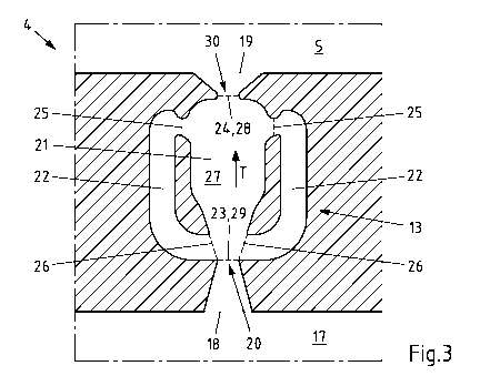
One of the similarly designed feed channels 13 of the cell frame 4 of Fig. 2
is shown in
Fig. 3. The shown feed channel 13 has an inlet opening 18 and an outlet
opening 19.
Date Recue/Date Received 2022-12-20
CA 03187791 2022-12-20
- 18 -
The positions of the inlet opening 18 and the outlet opening 19 can be
determined in
the shown feed channel 13 so that the outlet opening 19 defines the direct
transition
from the feed channel 13 to the cell interior 5 and that the inlet opening 18
is
arranged at the beginning of a widening of the free flow cross-section. In the
case of
the feed channel 13 shown, the inlet opening 18 can respectively be assumed to
be at a
constriction 20 of the free flow cross-section for the electrolyte. However,
it is
generally not necessary that a respective constriction 20 exists at which a
narrowing
free flow cross-section merges into a widening free flow cross-section. In the
feed
channel 13 shown, the inlet opening 18 for the electrolyte to be fed to the
cell interior
5 is also provided shortly before or adjacent to a region of the feed channel
13 in
which a transport channel 21 and two return channels 22 are connected to one
another. The transport channel 21 serves to transport the electrolyte to be
fed to the
cell interior 5. Thus, the transport channel 21 connects, at least in
sections, the inlet
opening 18 and the outlet opening 19 of the feed channel 13 with each other.
In this case, the inlet opening 23 of the transport channel 21 can coincide
with the
inlet opening 18 of the feed channel 13, as is noted in the case of the feed
channel 13
shown, or the inlet opening 23 of the transport channel 21 is spaced from the
inlet
opening 18 of the feed channel 13 in the transport direction T of the
electrolyte to be
fed into the direction of the cell interior 5. However, an opposite spacing of
the inlet
openings 18, 23 is not provided in principle. Analogously, the outlet opening
24 of the
transport channel 21 can coincide with the outlet opening 19 of the feed
channel 13
or, however, can be arranged before the outlet opening 19 of the feed channel
13 in
the transport direction T of the electrolyte to be fed into the direction of
the cell
interior 5.
In addition to the transport channel 21, the feed channel 13 shown and
preferred to
that extent also comprises two return channels 22, which are arranged on
opposite
sides of the transport channel 21 and via which part of the electrolyte to be
fed is
returned instead of being fed to the cell interior 5. From the transport
channel 21, the
electrolyte to be returned enters the return channels 22 via the entry
openings 25, in
Date Recue/Date Received 2022-12-20
CA 03187791 2022-12-20
- 19 -
order to be returned along the return channels 22 counter to the transport
direction T
of the electrolyte in the transport channel 21, in order then to get back
again into the
transport channel 21 via exit openings 26.
The transport channel 21 comprises a flow chamber 27, which is arranged at
least in
sections between the exit openings 26 and the entry openings 25 of the return
channels 22. The flow chamber 27 has a larger cross-sectional area of the free
flow
cross-section compared to the inlet opening 18 of the feed channel 13 and/or
the inlet
opening 23 of the transport channel 21. In this way, significantly different
flow
conditions can form in the flow chamber 27. In the case of the feed channel 13
shown
and preferred to that extent, the cross-sectional area of the free flow cross-
section of
the outlet opening 19 of the feed channel 13 is larger than the cross-
sectional area of
the free flow cross-section of the outlet opening 28 of the flow chamber 27,
so that the
feed channel 13 widens after the flow chamber 27 in the direction of the cell
interior 5
and thus enables that the electrolyte to be fed to the cell interior 5 can
flow in
different directions into the cell interior 5. This is also facilitated by the
feed channel
13 merging into the cell interior 5 adjacent to the respective widening of the
free flow
cross-section. Since the transport channel 21 or the feed channel 13 widens in
a
funnel shaped-manner directly after the flow chamber 27 in the transport
direction T
of the electrolyte to be fed, the feed channel 13 is preferably designed
relatively short.
In Figs. 4A-D, the feed channel 13 is shown with electrolyte to be fed flowing
through
at different points of time. First, the basic flow conditions in the feed
channel 13 are
described by means of Fig. 4A, wherein reference is made in the following to
the
reference signs of Fig. 3 for the sake of clarity. The electrolyte to be fed
flows into the
feed channel 13 via the inlet opening 18 and then gets into the flow chamber
27 of the
transport channel 21, in which the cross-sectional area of the free flow cross-
section
corresponds to approximately three or four times the cross-sectional area in
the
region of the inlet opening 23,29 of the transport channel 21 respectively of
the flow
chamber 27. Thus, after the inlet opening 23, in the region of the flow
chamber 27, a
kind of free jet into the flow chamber 27 is formed. Thus, the flow chamber 27
is not
Date Recue/Date Received 2022-12-20
CA 03187791 2022-12-20
- 20 -
flowed through uniformly, but a main flow is formed which comprises at least
the
majority of the volume flow of the electrolyte to be fed. Outside the main
flow in the
flow chamber 27 of the transport channel 21, in contrast, the flow velocity is
significantly lower, which is why significantly less electrolyte flows here.
In addition,
the portion of the electrolyte flowing there is also swirled to a large
extent.
For basic fluid dynamic principles, the flow of electrolyte that enters the
flow chamber
27 in the manner of a free jet will tend to lie against the wall of the flow
chamber 27.
According to the illustration of Fig. 4A, here the main flow of the
electrolyte in the flow
chamber 27 has lied against the left side of the flow chamber 27 and extends
on this
side into the direction of the end of the flow chamber 27 assigned to the cell
interior 5
and thus into the direction of the outlet openings 19,24 of the transport
channel 21
and of the feed channel 13 as such. Since the main flow flows along the left
side of the
flow chamber 27, the main flow gets at a certain angle into the direction of
the end of
the flow chamber 27 in the region of a constriction 30. At the constriction 30
respectively the taper of the flow chamber 27, the cross-sectional area of the
free flow
cross-section is about three or four times smaller than in a central section
of the flow
chamber 27. After the end of the flow chamber 27 respectively the constriction
30, the
transport channel 21 respectively the feed channel 13 widens so that the free
flow
cross-section becomes larger. For this reason, the main flow of the
electrolyte from
the flow chamber 27 can also flow out of the outlet opening 19,24 of the
transport
channel 21 respectively of the feed channel 13 into the cell interior 5 at a
similar angle
at which the main flow flows into the constriction 30.
However, part of the main flow of the electrolyte does not get through the
constriction
30, but is pushed into the return channels 22 through an entry opening 25
arranged in
the transport direction T of the electrolyte before the end of the flow
chamber 27.
Along the return channels 22, the electrolyte to be returned is returned
counter to the
transport direction T of the electrolyte in the flow chamber 27 and is guided
through
the exit openings 26 in the region of the beginning of the flow chamber 27
respectively the beginning of the transport channel 21 back into the flow
chamber 27
Date Recue/Date Received 2022-12-20
CA 03187791 2022-12-20
- 21 -
respectively the transport channel 21. There, the returned electrolyte
interacts with
the free jet of the electrolyte to be fed, the free jet being directed into
the flow
chamber 27.
In the case shown in Fig. 4A, not the same volume flow of electrolyte is
returned via
the two return channels 22. Since the main flow of the electrolyte flows along
the left
side of the flow chamber 27, much more electrolyte is also pushed into the
left return
channel 22 than into the opposite right return channel 22. As a result of
this, much
more electrolyte also flows out of the exit opening of the left return channel
22. Since,
in the case of the feed channel 13 shown and preferred to that extent, the
returned
electrolyte exits from the exit openings 26 approximately at right angles with
respect
to the original direction of the free jet, the free jet is deflected by the
returned
electrolyte to the right towards the wall of the flow chamber 27 there, as
shown in the
sequence of Fig. 4B. The main flow of the electrolyte to be fed thus changes
after a
certain time and then flows along the right side of the flow chamber 27 into
the
direction of the cell interior 5.
This is shown in Fig. 4C. The main flow then flows at an opposite angle into
the
constriction 30 at the end of the flow chamber 27 and, due to the design of
the feed
.. channel 13, also at a similar angle out of the feed channel 13 as well as
into the cell
interior 5. However, due to the relocation of the main flow in the flow
chamber 27,
more electrolyte is also returned via the right return channel 22 than via the
left
return channel 22, so that the returned electrolyte exiting from the right
exit opening
26 of the right return channel 22 pushes the free jet in this region to the
left again, as
shown in Fig. 4D. As a result of this, the main flow of the electrolyte to be
fed changes
again back to the left, so that the previously described cycle takes place
again. In the
course of this, the cycle time and thus the respective frequency remains at
least
substantially constant if the volume flow of the electrolyte to be fed is also
at least
substantially constant.
Date Recue/Date Received 2022-12-20
CA 03187791 2022-12-20
- 22 -
List of reference signs
1 cell stack
2 cell
3 half cell
4 cell frame
5 cell interior
6 electrode
7 semipermeable membrane
8 outer side
9 sealing surface
10 sealing material
11 supply line
12 disposal line
13 feed channel
14 discharge channel
15 bores
16 frame shell
17 collecting line
18 inlet opening
19 outlet opening
20 constriction
21 transport channel
22 return channel
23 inlet opening
24 outlet opening
25 entry opening
26 exit opening
27 flow chamber
28 outlet opening
29 inlet opening
30 constriction
T transport direction
Date Recue/Date Received 2022-12-20