Note: Descriptions are shown in the official language in which they were submitted.
CA 03187970 2022-12-21
WO 2022/043785
PCT/IB2021/056672
ETHYLENE INTERPOLYMER PRODUCTS HAVING A
MELT FLOW-INTRINSIC VISCOSITY INDEX (MFIVI)
BACKGROUND ART
Solution polymerization processes are typically carried out at temperatures
that are above the melting point of the ethylene homopolymer or copolymer
produced. In a typical solution polymerization process, catalyst components,
solvent, monomers and hydrogen are fed under pressure to one or more reactors.
For ethylene polymerization, or ethylene copolymerization, reactor
temperatures can range from 80 C to 300 C while pressures generally range from
3 MPag to 45 MPag. The ethylene homopolymer or copolymer produced remains
dissolved in the solvent under reactor conditions. The residence time of the
solvent
in the reactor is relatively short, for example, from 1 second to 20 minutes.
The
solution process can be operated under a wide range of process conditions that
allow the production of a wide variety of ethylene polymers. Post reactor, the
polymerization reaction is quenched to prevent further polymerization, by
adding a
catalyst deactivator. Optionally, the deactivated solution may be passivated
by
adding an acid scavenger. The deactivated solution, or optionally the
passivated
solution, is then forwarded to polymer recovery where the ethylene homopolymer
or
copolymer is separated from process solvent, unreacted residual ethylene and
unreacted optional a-olefin(s).
In solution polymerization there is a need for improved processes that
produce ethylene interpolymers at higher production rates, i.e. the pounds of
ethylene interpolymer produced per hour is increased. Higher production rates
increase the profitability of the solution polymerization plant. The catalyst
formulations and solution polymerization processes disclosed herein satisfy
this
need.
In solution polymerization there is also a need to increase the molecular
weight of the ethylene interpolymer produced at a given reactor temperature.
Given a specific catalyst formulation, it is well known to those of ordinary
experience that polymer molecular weight increases as reactor temperature
decreases. However, decreasing reactor temperature can be problematic when the
viscosity of the solution becomes too high. As a result, in solution
polymerization
1
CA 03187970 2022-12-21
WO 2022/043785 PCT/IB2021/056672
there is a need for catalyst formulations that produce high molecular weight
ethylene interpolymers at high reactor temperatures (or lower reactor
viscosities).
The catalyst formulations and solution polymerization processes disclosed
herein
satisfy this need.
In the solution polymerization process there is also a need for catalyst
formulations that are very efficient at incorporating one or more a-olefins
into a
propagating macromolecular chain. In other words, at a given [a-
olefin/ethylene]
weight ratio in a solution polymerization reactor, there is a need for
catalyst
formulations that produce lower density ethylene/a-olefin copolymers.
Expressed
.. alternatively, there is a need for catalyst formulations that produce an
ethylene/a-
olefin copolymer, having a specific density, at a lower [a-olefin/ethylene]
weight
ratio in the reactor feed. Such catalyst formulations efficiently utilize the
available
a-olefin and reduce the amount of a-olefin in solution process recycle
streams.
The catalyst formulations and solution process disclosed herein, produce
.. unique ethylene interpolymer products that have desirable properties in a
variety of
end-use applications. One non-limiting end-use application includes packaging
films containing the disclosed ethylene interpolymer products. Non-limiting
examples of desirable film properties include improved optical properties,
lower
seal initiation temperature and improved hot tack performance. Films prepared
from the ethylene interpolymer products, disclosed herein, have improved
properties.
SUMMARY OF DISCLOSURE
In this disclosure ethylene interpolymer products are disclosed comprising at
least two ethylene interpolymers, wherein the ethylene interpolymer product
has: a
dimensionless Melt Flow-Intrinsic Viscosity Index value, MFIVI, of from 0.05
to
n
0.80, a first derivative of a melt flow distribution function dLog(111)
, dLog(loading) at a loading
of 4000 g, of from -1.85 to -1.51; a residual catalytic metal of from 0.03 to
5
ppm of hafnium and a dimensionless unsaturation ratio, UR, of from > 0.06 to
0.60. The ethylene interpolymer product may have a melt index (12) from 0.3 to
.. 500 dg/minute, a density from 0.855 to 0.975 g/cc and contain from 0 to 25
mole
percent of one or more a-olefins. Suitable a-olefins include one or more C3 to
C10
a-olefins. Embodiments of the ethylene interpolymer product may have a
polydispersity, Mw/Mn, from 1.7 to 25, where Mw and Mn are the weight and
number
2
CA 03187970 2022-12-21
WO 2022/043785 PCT/IB2021/056672
average molecular weights, respectively, as determined by conventional size
exclusion chromatography (SEC). Embodiments of the ethylene interpolymer
products may have a CDBI50 from 1% to 98%, where CDBI50 is measured using
CTREF.
Additional embodiments include the manufacture of said ethylene
interpolymer products using a continuous solution polymerization process
employing at least one bridged metallocene catalyst formulation comprising a
component A defined by Formula (I)
R1
X (R6)
R4
M-X(R6)
R5/ R3
R2 µ111
(I)
where M is a metal selected from titanium, hafnium and zirconium; G is the
element
carbon, silicon, germanium, tin or lead; X represents a halogen atom, R6
groups are
independently selected from a hydrogen atom, a C1-20 hydrocarbyl radical, a C1-
20
alkoxy radical or a C6-10 aryl oxide radical, these radicals may be linear,
branched
or cyclic or further substituted with halogen atoms, Ci-io alkyl radicals, Ci-
io alkoxy
.. radicals, C6-10 aryl or aryloxy radicals; Ri represents a hydrogen atom, a
C1-20
hydrocarbyl radical, a C1-20 alkoxy radical, a C6-10 aryl oxide radical or
alkylsilyl
radicals containing at least one silicon atom and C3-30 carbon atoms; R2 and
R3 are
independently selected from a hydrogen atom, a C1-20 hydrocarbyl radical, a Ci-
20
alkoxy radical, a C6-10 aryl oxide radical or alkylsilyl radicals containing
at least one
silicon atom and C3-30 carbon atoms; and R4 and R5 are independently selected
from a hydrogen atom, a C1-20 hydrocarbyl radical, a C1-20 alkoxy radical a C6-
10 aryl
oxide radical, or alkylsilyl radicals containing at least one silicon atom and
C3-30
carbon atoms.
3
CA 03187970 2022-12-21
WO 2022/043785 PCT/IB2021/056672
Further embodiments include an improved continuous solution
polymerization process where the improved process comprises: polymerizing
ethylene and optionally at least one a-olefin, in a process solvent, in one or
more
reactors using a bridged metallocene catalyst to form the ethylene
interpolymer
product; where the improved process has an increased production rate, PR',
defined by the following formula:
PR' = 100 x (PRA- pRC) / pRC 10%
where PRA is the production rate of the improved process and PRc is a
comparative
production rate of a comparative continuous solution polymerization process
where
the bridged metallocene catalyst formulation has been replaced with an
unbridged
single site catalyst formulation.
Additional embodiments include a bridged metallocene catalyst formulation
comprising: an alumoxane co-catalyst (component M); a boron ionic activator
(component B); and optionally, a hindered phenol (component P). Non-limiting
examples of components M, B and P include: methylalumoxane (MMAO-7), trityl
tetrakis (pentafluoro-phenyl) borate and 2,6-di-tert-butyl-4-ethylphenol,
respectively.
Other embodiments include an improved continuous solution polymerization
process where an ethylene interpolymer product is formed by polymerizing
ethylene, and optionally at least one a-olefin, in a process solvent, in one
or more
reactors, using a bridged metallocene catalyst formulation and the improved
process is characterized by (a) and/or (b):
(a) the ethylene interpolymer product has at least a 10% improved
(higher) weight average molecular weight, Mw, as defined by the following
formula:
% Improved Mw = 100 x (mwA_mwc)/mwc 10%
where MA is a weight average molecular weight of the ethylene interpolymer
product produced using the improved process and Mwc is a comparative weight
average molecular weight of a comparative ethylene interpolymer product; where
the comparative ethylene interpolymer product is produced in a comparative
process by replacing the bridged metallocene catalyst formulation with an
.. unbridged single site catalyst formulation;
(b) an [a-olefin/ethylene] weight ratio, employed in the improved process,
is reduced (improved) by at least 70% as defined by the following formula:
4
CA 03187970 2022-12-21
WO 2022/043785 PCT/IB2021/056672
olefin'
< (a ¨ olefi
a ¨ ole fin (a¨ ethylene) ethylene)
% Reduced [ ______________ ] = 100 x < ¨70%
ethylene I ( a ¨ olefilc
s. ethylene
where (a-olefin/ethylene)' represents the weight of the a-olefin added to the
improved process divided by the weight of ethylene added to the improved
process,
where the ethylene interpolymer product having a target density is produced by
a
bridged metallocene catalyst formulation; and (a-olefin/ethylene)c represents
a
comparative weight ratio required to produce a comparative ethylene
interpolymer
product having the target density, where the comparative ethylene interpolymer
product is synthesized in a comparative process by replacing the bridged
metallocene catalyst formulation with an unbridged single site catalyst
formulation.
Embodiments of the ethylene interpolymer products disclosed herein may
comprise a first and a second ethylene interpolymer, synthesized using one or
more bridged metallocene catalyst formulations comprising a component A
defined
by Formula (I). Additional embodiments of the ethylene interpolymer products
disclosed herein may comprise a first and a third ethylene interpolymer,
synthesized using one or more bridged metallocene catalyst formulations
comprising a component A defined by Formula (I). Still further embodiments of
the
ethylene interpolymer products disclosed herein may comprise a first, a second
and
a third ethylene interpolymer, synthesized using one or more bridged
metallocene
catalyst formulations comprising a component A defined by Formula (I).
The first ethylene interpolymer may comprise from 5 to 100 wt.% of the
ethylene interpolymer product. The second ethylene interpolymer may comprise
from 0 to 95 wt.% of the ethylene interpolymer product. The third ethylene
interpolymer may comprise from 0 to 30 wt.% of the ethylene interpolymer
product.
Weight percent, wt.%, is the weight of the first, the second or the third
ethylene
interpolymer, individually, divided by the total weight of the ethylene
interpolymer
product, melt index is measured according to ASTM D1238 (2.16 kg load and
190 C) and density is measured according to ASTM D792.
The upper limit on the CDBI50 of the ethylene interpolymer product may be
98%, in other cases 90% and in still other cases 85%. An ethylene interpolymer
product with a CDBI50 of 98% results when an a-olefin is not added to the
continuous solution polymerization process; in these embodiments the ethylene
5
CA 03187970 2022-12-21
WO 2022/043785 PCT/IB2021/056672
interpolymer product is an ethylene homopolymer. The lower limit on the CDBI50
of
an ethylene interpolymer product may be 1%, in other cases 2% and in still
other
cases 3%; in these embodiments the ethylene interpolymers that comprise the
ethylene interpolymer product have significantly different densities (or a-
olefin
contents).
The lower limit on the Mw/Mn of the ethylene interpolymer product may be
1.8, in other cases 1.9 and in still other cases 2.0; in these embodiments,
the
weight average molecule weights, Mw's, of the ethylene interpolymers that
comprise
the ethylene interpolymer product are similar. The upper limit on the Mw/Mn of
the
ethylene interpolymer product may be 25, in other cases 20 and in still other
cases
15; in these embodiments, the weight average molecule weights, Mw's, of the
ethylene interpolymers that comprise the ethylene interpolymer product are
significantly different.
In this disclosure the amount of long chain branching in the ethylene
interpolymer products is characterized by the Melt Flow-Intrinsic Viscosity
Index
(MFIVI), fully described below. Ethylene interpolymer products have MFIVI
values
ranging from 0.05 to 0.80 (dimensionless). The upper limit on the MFIVI of an
ethylene interpolymer product may be 0.8, in other cases 0.7 and in still
other
cases 0.6. The lower limit on the MFIVI of an ethylene interpolymer product is
0.05.
Ethylene interpolymer products are further characterized by a first derivative
(111n)
of the melt flow distribution function dLog at a loading of 4000 g having
dLog(loading)
dLog(111n)
values from -1.85 to -1.51. The lower limit on ______________________________
at a loading of 4000 g
dLog(loading)
value of the ethylene interpolymer product may be -1.85, in other cases -1.80
n
and in still other cases dLog fi)
-1.75. The upper limit on dLog(loading) at a loading of
4000 g value of the ethylene interpolymer product may be -1.510, in other
cases
-1.515 and in still other cases -1.520.
In this disclosure, the Unsaturation Ratio CUR was used to characterize the
degree of unsaturation in ethylene interpolymers. In some embodiments the
upper
limit on the UR of the ethylene interpolymer product may be 0.60, in other
cases
0.55 and in still other cases 0.50 (dimensionless), and the lower limit on the
UR
6
CA 03187970 2022-12-21
WO 2022/043785 PCT/IB2021/056672
of the ethylene interpolymer product may be > 0.06, in other cases > 0.062 and
in
still other cases >0.065.
In this disclosure the amount of residual catalytic metal in ethylene
interpolymers was characterized by Neutron Activation Analysis `NAA'. The
disclosed ethylene interpolymer products are characterized by a residual
catalytic
metal comprising from 0.03 to 5 ppm of hafnium. The upper limit on the
residual catalytic metal in the ethylene interpolymer product may be 5.0 ppm,
in
other cases 4.0 ppm and in still other cases 3.0 ppm of hafnium; and the lower
limit
on the residual catalytic metal in the ethylene interpolymer product may be
0.03
ppm, in other cases 0.09 ppm and in still other cases 0.15 ppm hafnium.
Non-limiting embodiments of manufactured articles include a film comprising
at least one layer comprising an ethylene interpolymer product comprising at
least
two ethylene interpolymers; wherein the ethylene interpolymer product has: a
Melt
Flow-Intrinsic Viscosity Index value, MFIVI, of from 0.05 to 0.80; a first
n
derivative of a melt flow distribution function dLog(111)
,
at a loading of 4000 g, of
dLog (loading)
from -1.85 to -1.51;a residual catalytic metal of from 0.03 to 5 ppm of
hafnium; and a dimensionless unsaturation ratio, UR, of from > 0.060 to 0.60.
In
other embodiments this film may have an Elmendorf MD tear strength that is 18%
higher (improved) and a film haze that is 16% lower (improved); relative to a
film
prepared from Comparative Example 1.
Additional film embodiments include films where the at least one layer
further comprises at least one second polymer; where the second polymer may be
one or more ethylene polymers, one or more propylene polymers or a mixture of
ethylene polymers and propylene polymers. Further embodiments include films
having a total thickness from 0.5 mil to 10 mil. Other embodiments include
multilayer films that have from 2 to 11 layers, where at least one layer
comprises at
least one ethylene interpolymer product.
BRIEF DESCRIPTION OF DRAWINGS
The following Figures are presented for the purpose of illustrating selected
embodiments of this disclosure.
Figure 1 compares average Unsaturation Ratio CUR values of: Examples 20
through 27, relative to Comparatives Q through V, Comparatives 1 through 5 and
Comparative Examples 1, 2 & 4.
7
CA 03187970 2022-12-21
WO 2022/043785 PCT/IB2021/056672
Figure 2 illustrates how to determine the melt flow distribution function, the
first derivative of the melt flow distribution function, If (open circle
symbol) and Cf
(open square symbol) using Example 22 as an illustrative example.
Figure 3 illustrates how to determine the Melt Flow-Intrinsic Viscosity Index
(MFIVI). Ethylene interpolymers that do not have long chain branching (LCB),
or
undetectable LCB, fall on the reference line. Deviation from the reference
line
indicates the presence of LCB.
Figure 4 compares the sum of unsaturation ratio and the first derivative of
the melt flow distribution function at a loading of 4000 g for ethylene
interpolymer
product Examples 20-27, relative to Comparatives 01-04, W1 and W2 and
Comparative Examples 1 and 2.
Figure 5 illustrates embodiments of a continuous solution polymerization
process employing one CSTR reactor (vessel 11a) and one tubular reactor
(vessel
17).
Figure 6 illustrates embodiments of a continuous solution polymerization
process employing two CSTR reactors (vessels 111a and 112a) and one tubular
reactor (vessel 117). The two CSTR may be operated in series or parallel
modes.
Figure 7 illustrates the deconvolution of an ethylene interpolymer product
Comparative Example 4 into a first, second and third ethylene interpolymer.
DESCRIPTION OF EMBODIMENTS
Definition of Terms
Other than in the examples or where otherwise indicated, all numbers or
expressions referring to quantities of ingredients, extrusion conditions, etc.
used in
the specification and claims are to be understood as modified in all instances
by the
term 'about'. Accordingly, unless indicated to the contrary, the numerical
parameters set forth in the following specification and attached claims are
approximations that can vary depending upon the desired properties that the
various embodiments desire to obtain. At the very least, and not as an attempt
to
limit the application of the doctrine of equivalents to the scope of the
claims, each
numerical parameter should at least be construed in light of the number of
reported
significant digits and by applying ordinary rounding techniques. The numerical
values set forth in the specific examples are reported as precisely as
possible. Any
numerical values, however, inherently contain certain errors necessarily
resulting
from the standard deviation found in their respective testing measurements.
8
CA 03187970 2022-12-21
WO 2022/043785 PCT/IB2021/056672
It should be understood that any numerical range recited herein is intended
to include all sub-ranges subsumed therein. For example, a range of "1 to 10"
is
intended to include all sub-ranges between and including the recited minimum
value of 1 and the recited maximum value of 10; that is, having a minimum
value
equal to or greater than 1 and a maximum value of equal to or less than 10.
Because the disclosed numerical ranges are continuous, they include every
value
between the minimum and maximum values. Unless expressly indicated
otherwise, the various numerical ranges specified in this application are
approximations.
All compositional ranges expressed herein are limited in total to and do not
exceed 100 percent (volume percent or weight percent) in practice. Where
multiple
components can be present in a composition, the sum of the maximum amounts of
each component can exceed 100 percent, with the understanding that, and as
those skilled in the art readily understand, that the amounts of the
components
actually used will conform to the maximum of 100 percent.
In order to form a more complete understanding of this disclosure the
following terms are defined and should be used with the accompanying figures
and
the description of the various embodiments throughout.
As used herein, the term "monomer" refers to a small molecule that may
chemically react and become chemically bonded with itself or other monomers to
form a polymer.
As used herein, the term "a-olefin" is used to describe a monomer having a
linear hydrocarbon chain containing from 3 to 20 carbon atoms having a double
bond at one end of the chain; an equivalent term is "linear a-olefin".
As used herein, the term "ethylene polymer", refers to macromolecules
produced from ethylene and optionally one or more additional monomers;
regardless of the specific catalyst or specific process used to make the
ethylene
polymer. In the polyethylene art, the one or more additional monomers are
frequently called "comonomer(s)" and often include a-olefins. The term
"homopolymer" refers to a polymer that contains only one type of monomer.
Common ethylene polymers include high density polyethylene (HDPE), medium
density polyethylene (MDPE), linear low density polyethylene (LLDPE), very low
density polyethylene (VLDPE), ultralow density polyethylene (ULDPE), plastomer
9
CA 03187970 2022-12-21
WO 2022/043785 PCT/IB2021/056672
and elastomers. The term ethylene polymer also includes polymers produced in a
high pressure polymerization processes; non-limiting examples include low
density
polyethylene (LDPE), ethylene vinyl acetate copolymers (EVA), ethylene alkyl
acrylate copolymers, ethylene acrylic acid copolymers and metal salts of
ethylene
acrylic acid (commonly referred to as ionomers). The term ethylene polymer
also
includes block copolymers which may include 2 to 4 comonomers. The term
ethylene polymer also includes combinations of, or blends of, the ethylene
polymers described above.
The term "ethylene interpolymer" refers to a subset of polymers within the
"ethylene polymer" group that excludes polymers produced in high pressure
polymerization processes; non-limiting examples of polymer produced in high
pressure processes include LDPE and EVA (the latter is a copolymer of ethylene
and vinyl acetate).
The term "heterogeneous ethylene interpolymers" refers to a subset of
polymers in the ethylene interpolymer group that are produced using a
heterogeneous catalyst formulation; non-limiting examples of which include
Ziegler-
Natta or chromium catalysts.
The term "homogeneous ethylene interpolymer" refers to a subset of
polymers in the ethylene interpolymer group that are produced using
homogeneous
catalyst formulations. Typically, homogeneous ethylene interpolymers have
narrow
molecular weight distributions, for example Size Exclusion Chromatography
(SEC)
Mw/Mn values of less than 2.8; Mw and Mn refer to weight and number average
molecular weights, respectively. In contrast, the Mw/Mn of heterogeneous
ethylene
interpolymers are typically greater than the Mw/Mn of homogeneous ethylene
.. interpolymers. In general, homogeneous ethylene interpolymers also have a
narrow comonomer distribution, i.e. each macromolecule within the molecular
weight distribution has a similar comonomer content. Frequently, the
composition
distribution breadth index "CDBI" is used to quantify how the comonomer is
distributed within an ethylene interpolymer, as well as to differentiate
ethylene
interpolymers produced with different catalysts or processes. The "CDBI50" is
defined as the percent of ethylene interpolymer whose composition is within
50% of
the median comonomer composition; this definition is consistent with that
described
in U.S. Patent No. 5,206,075 assigned to Exxon Chemical Patents Inc. The
CDBI50
of an ethylene interpolymer can be calculated from TREF curves (Temperature
CA 03187970 2022-12-21
WO 2022/043785 PCT/IB2021/056672
Rising Elution Fractionation); the TREF method is described in Wild, et al.,
J.
Polym. Sci., Part B, Polym. Phys., Vol. 20 (3), pages 441-455. Typically the
CDBI50
of homogeneous ethylene interpolymers are greater than about 70%. In contrast,
the CDBI50 of a-olefin containing heterogeneous ethylene interpolymers are
generally lower than the CDB150 of homogeneous ethylene interpolymers. A blend
of two or more homogeneous ethylene interpolymers (that differ in comonomer
content) may have a CDBI50 less than 70%; in this disclosure such a blend may
be
referred to as a homogeneous blend or homogeneous composition. Similarly, a
blend of two or more homogeneous ethylene interpolymers (that differ in weight
average molecular weight (Mw)) may have a Mw/Mn 2.8; in this disclosure such a
blend may be referred to as a homogeneous blend or homogeneous composition.
In this disclosure, the term "homogeneous ethylene interpolymer" refers to
both linear homogeneous ethylene interpolymers and substantially linear
homogeneous ethylene interpolymers. In the art, linear homogeneous ethylene
interpolymers are generally assumed to have no long chain branches or an
undetectable amount of long chain branches; while substantially linear
ethylene
interpolymers are generally assumed to have greater than about 0.01 to about
3.0
long chain branches per 1000 carbon atoms. A long chain branch is
macromolecular in nature, i.e. similar in length to the macromolecule that the
long
chain branch is attached to.
In this disclosure, the term 'homogeneous catalyst' is defined by the
characteristics of the polymer produced by the homogeneous catalyst. More
specifically, a catalyst is a homogeneous catalyst if it produces a
homogeneous
ethylene interpolymer that has a narrow molecular weight distribution (SEC
Mw/Mn
values of less than 2.8) and a narrow comonomer distribution (CDBI50 > 70%).
Homogeneous catalysts are well known in the art. Two subsets of the
homogeneous catalyst genus include unbridged metallocene catalysts and bridged
metallocene catalysts. Unbridged metallocene catalysts are characterized by
two
bulky ligands bonded to the catalytic metal, a non-limiting example includes
.. bis(isopropyl-cyclopentadienyl) hafnium dichloride. In bridged metallocene
catalysts the two bulky ligands are covalently bonded (bridged) together, a
non-
limiting example includes diphenylmethylene (cyclopentadienyl) (2,7-di-t-
butylfuorenyl) hafnium dichloride; wherein the diphenylmethylene group bonds,
or
CA 03187970 2022-12-21
WO 2022/043785 PCT/IB2021/056672
bridges, the cyclopentadienyl and fluorenyl ligands together. Two additional
subsets of the homogeneous catalyst genus include unbridged and bridged single
site catalysts. In this disclosure, single site catalysts are characterized as
having
only one bulky ligand bonded to the catalytic metal. A non-limiting example of
an
unbridged single site catalyst includes cyclopentadienyl tri(tertiary
butyl)phosphinimine titanium dichloride. A non-limiting example of a bridged
single
site catalyst includes [C5(CH3)4 - Si(CH3)2 -N(tBu)] titanium dichloride,
where the
-Si(CH3)2 group functions as the bridging group.
Herein, the term "polyolefin" includes ethylene polymers and propylene
polymers; non-limiting examples of propylene polymers include isotactic,
syndiotactic and atactic propylene homopolymers, random propylene copolymers
containing at least one comonomer (e.g. a-olefins) and impact polypropylene
copolymers or heterophasic polypropylene copolymers.
The term "thermoplastic" refers to a polymer that becomes liquid when
heated, will flow under pressure and solidify when cooled. Thermoplastic
polymers
include ethylene polymers as well as other polymers used in the plastic
industry;
non-limiting examples of other polymers commonly used in film applications
include
barrier resins (EVOH), tie resins, polyethylene terephthalate (PET),
polyamides and
the like.
As used herein the term "monolayer film" refers to a film containing a single
layer of one or more thermoplastics.
As used herein, the terms "hydrocarbyl", "hydrocarbyl radical" or
"hydrocarbyl group" refers to linear, branched, or cyclic, aliphatic,
olefinic,
acetylenic and aryl (aromatic) radicals comprising hydrogen and carbon that
are
deficient by one hydrogen.
As used herein, an "alkyl radical" includes linear, branched and cyclic
paraffin radicals that are deficient by one hydrogen radical; non-limiting
examples
include methyl (-CH3) and ethyl (-CH2CH3) radicals. The term "alkenyl radical"
refers to linear, branched and cyclic hydrocarbons containing at least one
carbon-
carbon double bond that is deficient by one hydrogen radical.
As used herein, the term "aryl" group includes phenyl, naphthyl, pyridyl and
other radicals whose molecules have an aromatic ring structure; non-limiting
examples include naphthylene, phenanthrene and anthracene. An "arylalkyl"
group
12
CA 03187970 2022-12-21
WO 2022/043785
PCT/IB2021/056672
is an alkyl group having an aryl group pendant there from; non-limiting
examples
include benzyl, phenethyl and tolylmethyl; an "alkylaryl" is an aryl group
having one
or more alkyl groups pendant there from; non-limiting examples include tolyl,
xylyl,
mesityl and cumyl.
As used herein, the phrase "heteroatom" includes any atom other than
carbon and hydrogen that can be bound to carbon. A "heteroatom-containing
group" is a hydrocarbon radical that contains a heteroatom and may contain one
or
more of the same or different heteroatoms. In one embodiment, a heteroatom-
containing group is a hydrocarbyl group containing from 1 to 3 atoms selected
from
the group consisting of boron, aluminum, silicon, germanium, nitrogen,
phosphorous, oxygen and sulfur. Non-limiting examples of heteroatom-containing
groups include radicals of imines, amines, oxides, phosphines, ethers,
ketones,
oxoazolines heterocyclics, oxazolines, thioethers, and the like. The term
"heterocyclic" refers to ring systems having a carbon backbone that comprise
from
1 to 3 atoms selected from the group consisting of boron, aluminum, silicon,
germanium, nitrogen, phosphorous, oxygen and sulfur.
As used herein the term "unsubstituted" means that hydrogen radicals are
bounded to the molecular group that follows the term unsubstituted. The term
"substituted" means that the group following this term possesses one or more
.. moieties that have replaced one or more hydrogen radicals in any position
within
the group; non-limiting examples of moieties include halogen radicals (F, Cl,
Br),
hydroxyl groups, carbonyl groups, carboxyl groups, amine groups, phosphine
groups, alkoxy groups, phenyl groups, naphthyl groups, Ci to Cio alkyl groups,
C2
to Cio alkenyl groups, and combinations thereof. Non-limiting examples of
substituted alkyls and aryls include: acyl radicals, alkylamino radicals,
alkoxy
radicals, aryloxy radicals, alkylthio radicals, dialkylamino radicals,
alkoxycarbonyl
radicals, aryloxycarbonyl radicals, carbomoyl radicals, alkyl- and dialkyl-
carbamoyl
radicals, acyloxy radicals, acylamino radicals, arylamino radicals and
combinations
thereof.
Herein the term "R1" and its superscript form "Rl" refers to a first reactor
in a
continuous solution polymerization process; it being understood that R1 is
different
from the symbol Ri; the latter is used in chemical formula, e.g. representing
a
hydrocarbyl group. Similarly, the term "R2" and its' superscript form "R2"
refers to a
13
CA 03187970 2022-12-21
WO 2022/043785 PCT/IB2021/056672
second reactor, and; the term "R3" and it's superscript form "R3" refers to a
third
reactor.
As used herein, the term "oligomers" refers to an ethylene polymer of low
molecular weight, e.g., an ethylene polymer with a weight average molecular
weight (Mw) of about 2000 to 3000 daltons. Other commonly used terms for
oligomers include "wax" or "grease". As used herein, the term "light-end
impurities"
refers to chemical compounds with relatively low boiling points that may be
present
in the various vessels and process streams within a continuous solution
polymerization process; non-limiting examples include, methane, ethane,
propane,
butane, nitrogen, CO2, chloroethane, HCI, etc.
There is a need to improve the continuous solution polymerization process.
For example, to increase the molecular weight of the ethylene interpolymer
produced at a given reactor temperature. In addition, in solution
polymerization
there is a need for catalyst formulations that are very efficient at
incorporating one
or more a-olefins into the propagating macromolecular chain. Expressed in
different manner, there is a need for catalyst formulations that produce an
ethylene/a-olefin copolymer, having a specific density, at a lower (a-
olefin/ethylene)
ratio in the reactor feed. In addition, there is a need for ethylene
interpolymer
products that upon conversion into manufactured articles have improved
properties.
In the embodiments disclosed herein, 'a bridged metallocene catalyst
formulation' was employed in at least two solution polymerization reactors.
This
catalyst formulation included a bulky ligand-metal complex, 'Component A',
defined
by Formula (I).
R1
X (R6)
R4 M-X(R6)
R5/ 4iikR3
11411111
R2 (I)
14
CA 03187970 2022-12-21
WO 2022/043785 PCT/IB2021/056672
In Formula (I): non-limiting examples of M include Group 4 metals, i.e.
titanium, zirconium and hafnium; non-limiting examples of G include Group 14
elements, carbon, silicon, germanium, tin and lead; X represents a halogen
atom,
fluorine, chlorine, bromine or iodine; the R6 groups are independently
selected from
a hydrogen atom, a C1-20 hydrocarbyl radical, a C1-20 alkoxy radical or a C6-
10 aryl
oxide radical (these radicals may be linear, branched or cyclic or further
substituted
with halogen atoms, Ci-io alkyl radicals, Ci-io alkoxy radicals, C6-10 aryl or
aryloxy
radicals); Ri represents a hydrogen atom, a C1-20 hydrocarbyl radical, a C1-20
alkoxy
radical, a C6-10 aryl oxide radical or alkylsilyl radicals containing at least
one silicon
atom and C3-30 carbon atoms; R2 and R3 are independently selected from a
hydrogen atom, a C1-20 hydrocarbyl radical, a C1-20 alkoxy radical, a C6-10
aryl oxide
radical or alkylsilyl radicals containing at least one silicon atom and C3-30
carbon
atoms, and; R4 and R5 are independently selected from a hydrogen atom, a C1-20
hydrocarbyl radical, a C1-20 alkoxy radical a C6-10 aryl oxide radical, or
alkylsilyl
radicals containing at least one silicon atom and C3-30 carbon atoms.
In the art, a commonly used term for the X(R6) group shown in Formula (I) is
cleaving group', i.e. any ligand that can be abstracted from Formula (I)
forming a
catalyst species capable of polymerizing one or more olefin(s). An equivalent
term
for the X(R6) group is an cactivatable ligand'. Further non-limiting examples
of the
X(R6) group shown in Formula (I) include weak bases such as amines,
phosphines,
ethers, carboxylates and dienes. In another embodiment, the two R6 groups may
form part of a fused ring or ring system.
Further embodiments of component A include structural, optical or
enantiomeric isomers (meso and racemic isomers) and mixtures thereof of the
structure shown in Formula (I). While not to be construed as limiting, two
species
of component A include: diphenylmethylene(cyclopentadienyl)(2,7-di-t-
butylfuorenyl)hafnium dichloride having the molecular formula [(2,7-
tBu2Flu)Ph2C(Cp)HfC12]; and diphenylmethylene(cyclopentadienyl)(2,7-di-t-
butylfuorenyl)hafnium dimethyl having the molecular formula [(2,7-
tBu2Flu)Ph2C(Cp)HfMe2].
Embodiments of the ethylene interpolymer product include: (i) an ethylene
interpolymer product comprising a first and a second ethylene interpolymer
synthesized using one or more bridged metallocene catalyst formulation(s); or
(ii)
an ethylene interpolymer product comprising a first and a third ethylene
CA 03187970 2022-12-21
WO 2022/043785 PCT/IB2021/056672
interpolymer synthesized using one or more bridged metallocene catalyst
formulation(s); or (iii) an ethylene interpolymer product comprising a first,
a second
and a third ethylene interpolymer synthesized using one or more bridged
metallocene catalyst formulation(s). Embodiments include the manufacture of
the
first, the second and the third ethylene interpolymer in a first, a second and
a third
reactor, respectively. The first and second reactors may be operated in series
or
parallel mode. In series mode the effluent from the first reactor flows
directly into
the second reactor. In contrast, in parallel mode the effluent from the first
reactor
by-passes the second reactor and the effluent from the first and second
reactor are
combined downstream of the second reactor.
In Comparative 1 samples disclosed herein, e.g. Comparative la and lb, can
unbridged single site catalyst formulation' was employed in two solution
polymerization reactor. This catalyst formulation included a bulky ligand-
metal
complex, hereinafter 'Component C', defined by Formula (II):
(LA)aM(PI)b(Q)n (II)
In Formula (II): (LA) represents a bulky ligand; M represents a metal atom; PI
represents a phosphinimine ligand; Q represents a leaving group; a is 0 or 1;
b is 1
or 2; (a+b) = 2; n is 1 or 2; and the sum of (a+b+n) equals the valance of the
metal
M. Non-limiting examples of M in Formula (II) include Group 4 metals,
titanium,
zirconium and hafnium.
Non-limiting examples of the bulky ligand LA in Formula (II) include
unsubstituted or substituted cyclopentadienyl ligands or cyclopentadienyl-type
ligands, heteroatom substituted and/or heteroatom containing cyclopentadienyl-
type ligands. Additional non-limiting examples include,
cyclopentaphenanthreneyl
ligands, unsubstituted or substituted indenyl ligands, benzindenyl ligands,
unsubstituted or substituted fluorenyl ligands, octahydrofluorenyl ligands,
cyclooctatetraendiyl ligands, cyclopentacyclododecene ligands, azenyl ligands,
azulene ligands, pentalene ligands, phosphoyl ligands, phosphinimine, pyrrolyl
ligands, pyrozolyl ligands, carbazolyl ligands, borabenzene ligands and the
like,
including hydrogenated versions thereof, for example tetrahydroindenyl
ligands. In
other embodiments, LA may be any other ligand structure capable of n-bonding
to
the metal M, such embodiments include both n3-bonding and n5-bonding to the
metal M. In other embodiments, LA may comprise one or more heteroatoms, for
example, nitrogen, silicon, boron, germanium, sulfur and phosphorous, in
16
CA 03187970 2022-12-21
WO 2022/043785
PCT/IB2021/056672
combination with carbon atoms to form an open, acyclic, or a fused ring, or
ring
system, for example, a heterocyclopentadienyl ancillary ligand. Other non-
limiting
embodiments for LA include bulky amides, phosphides, alkoxides, aryloxides,
imides, carbolides, borollides, porphyrins, phthalocyanines, corrins and other
polyazomacrocycles.
The phosphinimine ligand, PI, is defined by Formula (III):
(RP)3 P = N - (III)
wherein the RP groups are independently selected from: a hydrogen atom; a
halogen atom; C1-20 hydrocarbyl radicals which are unsubstituted or
substituted with
one or more halogen atom(s); a C1-8 alkoxy radical; a C6-10 aryl radical; a C6-
10
aryloxy radical; an amido radical; a silyl radical of formula -Si(Rs)3,
wherein the Rs
groups are independently selected from, a hydrogen atom, a C1-8 alkyl or
alkoxy
radical, a C6-10 aryl radical, a C6-10 aryloxy radical, or a germanyl radical
of formula
-Ge(RG)3, wherein the RG groups are defined as Rs is defined in this
paragraph.
The leaving group Q is any ligand that can be abstracted from Formula (II)
forming a catalyst species capable of polymerizing one or more olefin(s). In
some
embodiments, Q is a monoanionic labile ligand having a sigma bond to M.
Depending on the oxidation state of the metal, the value for n is 1 or 2 such
that
Formula (II) represents a neutral bulky ligand-metal complex. Non-limiting
examples of Q ligands include a hydrogen atom, halogens, C1-20 hydrocarbyl
radicals, C1-20 alkoxy radicals, C5-10 aryl oxide radicals; these radicals may
be
linear, branched or cyclic or further substituted by halogen atoms, Ci-io
alkyl
radicals, Ci-io alkoxy radicals, C6-10 arly or aryloxy radicals. Further non-
limiting
examples of Q ligands include weak bases such as amines, phosphines, ethers,
carboxylates, dienes, hydrocarbyl radicals having from 1 to 20 carbon atoms.
In
another embodiment, two Q ligands may form part of a fused ring or ring
system.
Further embodiments of Component C include structural, optical or
enantiomeric isomers (meso and racemic isomers) and mixtures thereof of the
bulky ligand-metal complex shown in Formula (II).
While not to be construed as limiting, two species of component C include:
cyclopentadienyl tri(tertiary butyl) phosphinimine titanium dichloride having
the
molecular formula [Cp[(t-Bu)3PN]fiC12]; and cyclopentadienyl
tri(isopropyl)phosphinimine titanium dichloride having the molecular formula
[CpRisopropy1)3PNTiC12].
17
CA 03187970 2022-12-21
WO 2022/043785
PCT/IB2021/056672
The bridged metallocene catalyst formulation contains a component A
(defined above), a component MA, a component BA and a component PA.
Components M, B and P are defined below and the superscript "A" denotes that
fact
that the respective component was part of the catalyst formulation containing
component A, i.e. the bridged metallocene catalyst formulation.
In this disclosure Comparative ethylene interpolymer products were
prepared by employing an unbridged single site catalyst formulation. In these
Comparative samples, the unbridged single site catalyst formulation replaced
the
bridged metallocene catalyst formulation. The unbridged single site catalyst
formulation contains a component C (defined above), a component Mc, a
component BC and a component Pc. Components M, B and P are defined below
and the superscript "c" denoted that fact that the respective component was
part of
the catalyst formulation containing component C, i.e. the unbridged single
site
catalyst formulation.
The catalyst components M, B and P were independently selected for each
catalyst formulation. To be more clear: components MA and Mc may, or may not,
be the same chemical compound; components BA and BC may, or may not, be the
same chemical compound; and components PA and Pc may, or may not, be the
same chemical compound. Further, catalyst activity was optimized by
independently adjusting the mole ratios of the components in each catalyst
formulation.
Components M, B and P were not particularly limited, i.e. a wide variety of
components can be used as described below.
Component M functioned as a co-catalyst that activated component A or
component C, into a cationic complex that effectively polymerized ethylene, or
mixtures of ethylene and a-olefins, producing high molecular weight ethylene
interpolymers. In the bridged metallocene catalyst formulation and the
unbridged
single site catalyst formulation the respective component M was independently
selected from a variety of compounds and those skilled in the art will
understand
that the embodiments in this disclosure are not limited to the specific
chemical
compound disclosed. Suitable compounds for component M included an
alumoxane co-catalyst (an equivalent term for alumoxane is aluminoxane).
Although the exact structure of an alumoxane co-catalyst was uncertain,
subject
18
CA 03187970 2022-12-21
WO 2022/043785 PCT/IB2021/056672
matter experts generally agree that it was an oligomeric species that contain
repeating units of the general Formula (IV):
(R)2A10-(Al(R)-0)n-Al(R)2 (IV)
where the R groups may be the same or different linear, branched or cyclic
hydrocarbyl radicals containing 1 to 20 carbon atoms and n is from 0 to about
50.
A non-limiting example of an alumoxane was methyl aluminoxane (or MMAO-7)
wherein each R group in Formula (IV) is a methyl radical.
Component B was an ionic activator. In general, ionic activators are
comprised of a cation and a bulky anion; wherein the latter is substantially
non-
coordinating.
In the bridged metallocene catalyst formulation and the unbridged single site
catalyst formulation the respective component B was independently selected
from a
variety of compounds and those skilled in the art will understand that the
embodiments in this disclosure are not limited to the specific chemical
compound
disclosed. Non-limiting examples of component B were boron ionic activators
that
are four co-ordinate with four ligands bonded to the boron atom. Non-limiting
examples of boron ionic activators included the following Formulas (V) and
(VI)
shown below:
[R5] [B(R7)4]- (V)
where B represented a boron atom, R5 was an aromatic hydrocarbyl (e.g.
triphenyl
methyl cation) and each R7 was independently selected from phenyl radicals
which
were unsubstituted or substituted with from 3 to 5 substituents selected from
fluorine atoms, C1-4 alkyl or alkoxy radicals which were unsubstituted or
substituted
by fluorine atoms; and a silyl radical of formula -Si(R9)3, where each R9 was
independently selected from hydrogen atoms and C1-4 alkyl radicals; and
compounds of formula (VI):
[(1=19)2H] [B(R7)4]- (VI)
where B was a boron atom, H was a hydrogen atom, Z was a nitrogen or
phosphorus atom, t was 2 or 3 and R9 was selected from C1-8 alkyl radicals,
phenyl
radicals which were unsubstituted or substituted by up to three C1-4 alkyl
radicals,
or one R9 taken together with the nitrogen atom may form an anilinium radical
and
R7 was as defined above in Formula (VI).
In both Formula (V) and (VI), a non-limiting example of R7 was a
pentafluorophenyl radical. In general, boron ionic activators may be described
as
19
CA 03187970 2022-12-21
WO 2022/043785 PCT/IB2021/056672
salts of tetra(perfluorophenyl) boron; non-limiting examples include
anilinium,
carbonium, oxonium, phosphonium and sulfonium salts of
tetra(perfluorophenyl)boron with anilinium and trityl (or triphenylmethylium).
Additional non-limiting examples of ionic activators included:
triethylammonium
tetra(phenyl)boron, tripropylammonium tetra(phenyl)boron, tri(n-butyl)ammonium
tetra(phenyl)boron, trimethylammonium tetra(p-tolyl)boron, trimethylammonium
tetra(o-tolyl)boron, tributylammonium tetra(pentafluorophenyl)boron,
tripropylammonium tetra(o,p-dimethylphenyl)boron, tributylammonium tetra(m,m-
dimethylphenyl)boron, tributylammonium tetra(p-trifluoromethylphenyl)boron,
tributylammonium tetra(pentafluorophenyl)boron, tri(n-butyl)ammonium tetra(o-
tolyl)boron, N,N-dimethylanilinium tetra(phenyl)boron, N,N-diethylanilinium
tetra(phenyl)boron, N,N-diethylanilinium tetra(phenyl)n-butylboron, N,N-2,4,6-
pentamethylanilinium tetra(phenyl)boron, di-(isopropyl)ammonium
tetra(pentafluorophenyl)boron, dicyclohexylammonium tetra(phenyl)boron,
triphenylphosphonium tetra(phenyl)boron, tri(methylphenyl)phosphonium
tetra(phenyl)boron, tri(dimethylphenyl)phosphonium tetra(phenyl)boron,
tropillium
tetrakispentafluorophenyl borate, triphenylmethylium tetrakispentafluorophenyl
borate, benzene(diazonium)tetrakispentafluorophenyl borate, tropillium
tetrakis(2,3,5,6-tetrafluorophenyl)borate, triphenylmethylium tetrakis(2,3,5,6-
tetrafluorophenyl)borate, benzene(diazonium) tetrakis(3,4,5-
trifluorophenyl)borate,
tropillium tetrakis(3,4,5 -trifluorophenyl)borate, benzene(diazonium)
tetrakis(3,4,5-
trifluorophenyl)borate, tropillium tetrakis(1,2,2-trifluoroethenyl)borate,
triphenylmethylium tetrakis(1 ,2,2-trifluoroethenyl)borate, benzene(diazonium)
tetrakis(1,2,2-trifluoroethenyl)borate, tropillium tetrakis(2,3,4,5-
tetrafluorophenyl)borate, triphenylmethylium tetrakis(2,3,4,5-
tetrafluorophenyl)borate, and benzene(diazonium) tetrakis(2,3,4,5
tetrafluorophenyl)borate. Readily available commercial ionic activators
included
N,N-dimethylanilinium tetrakispentafluorophenyl borate, and triphenylmethylium
tetrakispentafluorophenyl borate.
Component P is a hindered phenol and is an optional component in the
respective catalyst formulation. In the bridged metallocene catalyst
formulation and
the unbridged single site catalyst formulation the respective component P was
independently selected from a variety of compounds and those skilled in the
art will
understand that the embodiments in this disclosure are not limited to the
specific
CA 03187970 2022-12-21
WO 2022/043785 PCT/IB2021/056672
chemical compound disclosed. Non-limiting example of hindered phenols included
butylated phenolic antioxidants, butylated hydroxytoluene, 2,4-di-
tertiarybuty1-6-
ethyl phenol, 4,4'-methylenebis (2,6-di-tertiary-butylphenol), 1,3, 5-
trimethy1-2,4,6-
tris (3,5-di-tert-butyl-4-hydroxybenzyl) benzene and octadecy1-3-(3',5'-di-
tert-butyl-
4'-hydroxyphenyl) propionate.
As fully described below, a highly active bridged metallocene catalyst
formulation was produced by optimizing the quantity and mole ratios of the
four
components in the formulation; i.e., component A, component MA, component BA
and optionally component PA. Where highly active means a very large amount of
ethylene interpolymer is produced from a very small amount of catalyst
formulation.
Similarly, a highly active unbridged single site catalyst formulation
(comparative
catalyst formulation) was produced by optimizing the quantity and mole ratios
of the
four components in the formulation; i.e., component C, component Mc, component
13c and optionally component Pc.
In this disclosure, the bridged metallocene catalyst formulation produced
ethylene interpolymer products having a unique unsaturation ratio, UR.
Table 1 discloses the amount of Internal, Side Chain and Terminal
unsaturations per 100 carbons (100C) in Examples 20-27 of this disclosure;
specifically, the amount of trans-vinylene, vinylidene and terminal vinyl
groups as
measured according to ASTM D3124-98 and ASTM D6248-98. Table 1 also
discloses the dimensionless Unsaturation Ratio', CUR', as defined by the
following
equation:
UR = s( cu_Tu)n-u Eq.(UR)
where SCu are the side chain unsaturations and Tu are the terminal
unsaturations.
Examples 20-27 have an average UR value of 0.155. Table 1 also discloses the
amount of Internal, Side Chain and Terminal unsaturations per 100 carbons
(100C)
in Comparative ethylene interpolymers. Graphically, Figure 1 compares average
UR values.
Comparative Q were commercial products called QUEOTM available from
Borealis, Vienna, Austria. In Table 1, Comparative 01 (i.e. Comp.Q1) was QUEO
0201, Comparative 02 was QUEO 8201, Comparative 03 was QUEO 0203 and
Comparative 04 was QUEO 1001. QUEO products are ethylene/1-octene
copolymers, believed to be produced in a solution polymerization process
employing one reactor and a metallocene catalyst formulation. In Table 1, the
21
CA 03187970 2022-12-21
WO 2022/043785 PCT/IB2021/056672
average UR value of Comparative R is the average of 7-samples of commercial
products called AFFINITY available from The Dow Chemical Company, Midland,
Michigan; specifically, AFFINITY PL1880 (3-samples), AFFINITY PF1140,
AFFINITY PF1142 and AFFINITY PL1881. The AFFINITY samples were
ethylene/1-octene copolymers believed to be produced in a solution
polymerization
process employing one reactor and a single site catalyst formulation. In Table
1,
the average UR of Comparative S is the average of 5-samples of commercial
products called ENABLE available from ExxonMobil Chemical Company, Spring,
Texas; specifically, ENABLE 27-03CH (3-samples) and ENABLE 20-05 (2-
samples). ENABLE products were ethylene/1-hexene copolymers, believed to be
produced in a gas phase process employing one reactor and a metallocene
catalyst formulation. In Table 1, the average UR of Comparative T is the
average
of 48-samples of commercial products called EXCEED available from ExxonMobil
Chemical Company, Spring, Texas; specifically, EXCEED 1018 (26-samples),
EXCEED 1023 (4-samples), EXCEED 1015 (3-samples), EXCEED 4518 (3-
samples), EXCEED 3518(4-samples), Exceed 1012 (3-samples), EXCEED
1318CA (2-samples), EXCEED 3812, EXCEED 1023DA and EXCEED 2718CB.
EXCEED products were ethylene/1-hexene copolymers believed to be produced in
a gas phase process employing one reactor and a metallocene catalyst
formulation. Comparative U, having a UR value of -0.667, was a commercial
product called ELITE AT 6202 available from The Dow Chemical Company,
Midland, Michigan. ELITE AT 6202 was an ethylene/1-hexene copolymer, believed
to be produced in a dual reactor solution process employing at least one
homogeneous catalyst formulation. In Table 1, the average UR of Comparative V
is the average of 25-samples of commercial products called ELITE available
from
The Dow Chemical Company, Midland, Michigan; specifically, ELITE 5400 (12-
samples), ELITE 5100 (4-samples), ELITE 5110 (2-samples), ELITE 5230 (2-
samples), ELITE 5101 and ELITE 5500. ELITE products were ethylene/1-octene
copolymers believed to be produced in a solution polymerization process
employing a single site catalyst formulation in a first reactor and a batch
Ziegler-
Natta catalyst formulation in a second reactor. In Table 1, the average UR of
Comparative 1 is the average of 61-samples of a commercial product called
SURPASS FPs117 available from NOVA Chemicals Corporation, Calgary,
Alberta. SURPASS FPs117 was an ethylene/1-octene copolymer produced in a
22
CA 03187970 2022-12-21
WO 2022/043785 PCT/IB2021/056672
solution polymerization process employing a single site catalyst formulation.
In
Table 1, the average UR of Comparative 2 is an average of 3-samples of an
experimental product manufactured by NOVA Chemicals Corporation, Calgary,
Alberta. Comparative 2a, 2b and 2c were ethylene/1-octene copolymers (about
0.917 g/cc and about 1.0 12) produced in a solution polymerization process
employing a bridged metallocene catalyst formulation in a first reactor and an
unbridged single site catalyst formulation in a second reactor. In Table 1,
the
average UR of Comparative 3 is the average of 4-samples of an experimental
product manufactured by NOVA Chemicals Corporation, Calgary, Alberta.
Comparative 3a, 3b, 3c and 3d were ethylene/1-octene copolymers (about 0.917
g/cc and about 1.0 12) produced in a solution polymerization process employing
a
bridged metallocene catalyst formulation in a first reactor and an in-line
Ziegler-
Natta catalyst formulation in a second reactor. In Table 1, the average UR of
Comparative 4 is the average of 21-samples of commercial products called
SURPASS available from NOVA Chemicals Corporation, Calgary, Alberta;
specifically, SURPASS SPs116 (6-samples), SURPASS SPsK919 (5-samples),
SURPASS VPsK114 (3-samples) and SURPASS VPsK914 (7-samples) were
ethylene/1-octene copolymers produced in a solution polymerization process
employing a single site catalyst formulation in a first reactor and an in-line
Ziegler-
Natta catalyst formulation in a second reactor. In Table 1, the average UR of
Comparative 5 is the average of 137-samples of a commercial product called
SCLAIR FP120 available from NOVA Chemicals Corporation, Calgary, Alberta.
FP120 was an ethylene/1-octene copolymer produced in a solution polymerization
process employing an in-line Ziegler-Natta catalyst formulation. Table 1
documents
the UR value of Comparative Examples 1, 2 and 4, which have an average UR
value of -0.147 as shown in Figure 1.
LCB is a structural feature in polyethylenes that is well known to those of
ordinary skill in the art. Traditionally, there are three methods to quantify
the
amount of LCB, namely, nuclear magnetic resonance spectroscopy (NMR), for
example see J.C. Randall, J Macromol. Sci., Rev. Macromol. Chem. Phys. 1989,
29, 201; triple detection SEC equipped with a DRI, a viscometer and a low-
angle
laser light scattering detector, for example see W.W. Yau and D.R. Hill, Int.
J.
Polym. Anal. Charact. 1996; 2:151; and rheology, for example see W.W.
Graessley, Acc. Chem. Res. 1977, 10, 332-339. A long chain branch is
23
CA 03187970 2022-12-21
WO 2022/043785 PCT/IB2021/056672
macromolecular in nature, i.e. long enough to be seen in an NMR spectra,
triple
detector SEC experiments or rheological experiments. A limitation with LCB
analysis via NMR is that it cannot distinguish branch length for branches
equal to or
longer than six carbon atoms (thus, NMR cannot be used to characterize LCB in
ethylene/1-octene copolymers, which have hexyl groups as side branches). The
triple detection SEC method measures the intrinsic viscosity ([0 (see W.W.
Yau,
D. Gillespie, Analytical and Polymer Science, TAPP! Polymers, Laminations, and
Coatings Conference Proceedings, Chicago 2000; 2: 699 or F. Beer, G. Capaccio,
L.J. Rose, J. Appl. Polym. Sci. 1999, 73: 2807 or P.M. Wood-Adams, J.M. Dealy,
A.W. deGroot, O.D. Redwine, Macromolecules 2000; 33: 7489). By referencing the
intrinsic viscosity of a branched polymer ([nib) to that of a linear one ([1)
at the
same molecular weight, the viscosity branching index factor g' (g'=[n]b/[n]i)
was
used for branching characterization. However, both short chain branching (SCB)
and long chain branching (LCB) make contribution to the intrinsic viscosity
([0,
.. effort was made to isolate the SCB contribution for ethylene/1-butene and
ethylene/1-hexene copolymers but not ethylene/1-octene copolymers (see Lue et
al., U.S. Patent No. 6,870,010 B1).
In this disclosure a new method was developed to quantify the amount of
long chain branching in ethylene/a-olefin interpolymers. This new method
.. correlates the melt flow index (MI) and intrinsic viscosity (IV) of the
resin of interest
and defines a new parameter called the Melt Flow-Intrinsic Viscosity Index
(MFIVI)
to quantify the degree of LCB in the resin. In this new method, the impacts of
molar
mass, molar mass distribution, bimodality in molar mass distribution,
comonomer
type and content were removed; allowing one to quantify the amount of long
chain
branching in different ethylene interpolymers.
The Melt Flow-Intrinsic Viscosity Index (MFIVI) is defined by the following
equation, Eq.1:
1.9507x(fbim0dalityxfc0m0nmer)0.21678
if
MFIVI = ________________________________________________ 1 Eq.1
/V+3.0122x10-6x(Comonomer Wt%)xM,(3.725
The various parameters in Eq.1 are fully described in the following
paragraphs.
The fbimodafity parameter in Eq.1 is defined by Eq.(2):
24
CA 03187970 2022-12-21
WO 2022/043785 PCT/IB2021/056672
_ i n(-0.94831xLog(Pd)-0.94322xCf-0.71879)
fbimo dality ¨ -.-,-, Eq.2
In Eq.(2) the Pd parameter represents the polydispersity of the ethylene
interpolymer of interest, where Pd is the conventional polydispersity as
measured
by Size Exclusion Chromatographs (SEC), i.e., Pd = Mw/Mn, where Mw and Mn are
the weight and number average molecular weights, respectively.
The parameter Cf, in Eq.2, is a Correction Factor for the ethylene
interpolymer of interest and is determined according to the following two step
procedure, i.e. steps (i) and (ii).
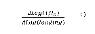
In step (i) the melt flow distribution function, Log(1/In), as defined by
Eq.(3),
is determined for the ethylene interpolymer of interest.
Log (1/I) = )60 + )61xLog (loading) + 132x(Log(loading))2 Eq.3
The melt flow distribution function is determined by plotting Log(1/In) versus
Log(loading), where In is the measured melt index of the ethylene interpolymer
of
interest at loadings of 21600, 10000, 6000 and 2160 grams (measured according
to
ASTM D1238 at 190 C.). The dotted curve in Figure 2 illustrates the melt flow
distribution function of Example 22, having 132,131 and Po values of -0.3673,
1.1166
and 0.4747, respectively; this polynomial fit has a least squares R2 value of
0.9951.
Table 2 documents the melt flow distribution functions of ethylene
interpolymer
product Examples 20-27, Comparative 01-04 and Comparative W1 and W2; as
well as Comparative Examples 1 and 2.
In step (ii) the first derivative of the melt flow distribution function was
calculated according to Eq.4:
dLog MO dLog (loading) 1 = )6 + 2x )62xLog (loading) Eq.4
The solid line in Figure 2 illustrates the first derivative of the melt flow
distribution function of Example 22 (Eq.4). The correction factor Cf (in Eq.2)
is the
value of the first derivative (Eq.4) at a loading of 4000 g. In the case of
Example
22, the Cf value was -1.529, as shown by the open square symbol in Figure 2
(Log(4000) = 3.6021). Table 3B documents Cf values of ethylene interpolymer
product Examples 20-27, Comparative la, Comparative Ql, 03 and 04 and
Comparative W1 and W2; as well as Comparative Examples 1 and 2.
CA 03187970 2022-12-21
WO 2022/043785 PCT/IB2021/056672
The ethylene interpolymer products of this disclosure are characterized by a
n
first derivative of the melt flow distribution function dLog (1 /I)
dLog (loading) at a loading of
4000 g having values from -1.85 to -1.51.
Returning to Eq.1 and the parameter If ; the If parameter represents a fitted
melt index. The open circle symbol in Figure 2 illustrates the If value of
Example
22, i.e. 1.857 as shown in Table 3B. To be more general, for any ethylene
interpolymer of interest the If value is determined by the value of the melt
flow
distribution function (Eq.3) at a loading of 4000 g. Table 3B documents the If
values of ethylene interpolymer product Examples 20-27, Comparative la,
Comparative Ql, 03 and 04, Comparative W1 and W2; as well as Comparative
Examples 1 and 2.
In Eq.1 the parameter Comonomer Wt% is the weight percent of comonomer
in the ethylene interpolymer of interest as measured by FTIR according to ASTM
D6645. Table 3B documents the Comonomer Wt% values of ethylene interpolymer
product Examples 20-27, Comparative la, Comparative Ql, 03 and 04,
Comparative W1 and W2; as well as Comparative Examples 1 and 2.
Turning to the parameter fcomonomer that appears in Eq.1. The fcomonomer value
used in Eq.1 is determined by the Comonomer Wt% value, specifically: if
Comonomer Wt% is >14.95%, the fcomonomer value used in Eq.1 is determined by
Eq.5; if Comonomer Wt% is 14.95%, the fcomonomer value used in Eq.1 is
determined by Eq.6.
= 10(0.018790x(Comonomer Wt%)-0.28053) E
fcomonomer q.5
fcomonomer = 1 Eq.6
Finally, the /V and Mv parameters in Eq.1 represent the intrinsic viscosity
and viscosity average molar mass, respectively, of the ethylene interpolymer
of
interest as determined by 3D-SEC. The 3D-SEC procedure is fully described in
this disclosure. Table 3B documents the /V and Mv values of ethylene
interpolymer
product Examples 20-27, Comparative la, Comparative Ql, 03 and 04,
Comparative W1 and W2; as well as Comparative Examples 1 and 2.
Figure 3 illustrates the calculation of Melt Flow-Intrinsic Viscosity Index
(MFIVI) as defined in Eq.1. MFIVI allows one to quantify the degree of long
chain
branching (LCB) in an ethylene interpolymer. In Figure 3, the term
26
CA 03187970 2022-12-21
WO 2022/043785
PCT/IB2021/056672
Log (f bimodalityXfcomonomer), as defined above, was plotted on the abscissa
(X); and
If
the term Log(IV + 3.0122x10⁻⁶x(Comonomer Wt%)xM, .725), as defined above,
was plotted on the ordinate (Y). Ethylene interpolymers having no LCB (or
undetectable LCB) are defined by the reference line window shown in Figure 3,
i.e.
Y = 0.2191X + 0.2917( 0.0197); more specifically, the solid line defined by
the
linear relationship Y = 0.2191X + 0.2917 and the upper dashed line (Y =
0.2191X +
0.3114) and the lower dash-dot line (Y = 0.2191X + 0.2720). This reference
window represents 45 ethylene interpolymers that did not contain long chain
branching. To improve the clarity of Figure 3, most reference resins were not
plotted in Figure 3; rather, the reference resins are disclosed in Table 3A.
Reference resins had Mw/Mn values ranging from 1.97 to 13.5, contained C8, or
C6,
or C4 a-olefin or no a-olefin and were produced in solution, gas phase or
slurry
processes using Ziegler-Natta, homogeneous and mixed (Ziegler-Natta +
homogeneous) catalyst formulations.
In this disclosure, resins having no LCB (or undetectable LCB) were
characterized by MFIVI values < 0.05, as evidenced by Table 3A; wherein
reference resins had MFIVI values ranging from -0.042 to 0.043. Two reference
resins were plotted in Figure 3: Comparative la (filled triangle symbol),
MFIVI =
0.037 (Table 3B); and Comparative T (filled diamond), MFIVI = -0.005 (Table
3B).
Comparative la was an ethylene/1-octene interpolymer produced using an
unbridged single site catalyst formulation in solution dual reactor process
commercially available as SURPASS FPs117-C NOVA Chemicals Corporation,
Calgary, Alberta. Comparative T was EXCEED 1018 available from ExxonMobil
Chemical Company, Spring, Texas; an ethylene/1-hexene interpolymer produced
using a single site catalyst formulation in a gas phase process. Table 3B
discloses
the MFIVI values of Comparatives R1, Si, S2, U, V2a, V2b and T; as well as the
values of the various parameters required to calculate MFIVI.
The ethylene interpolymer products of this disclosure where characterized
by the presence of long chain branching; specifically, the ethylene
interpolymer
products of this disclosure were characterized by a MFIVI value of from 0.05
to
0.80.
As shown in Table 3B ethylene interpolymer product Examples 20-27
contained long chain branching as evidenced by MFIVI values ranging from 0.315
27
CA 03187970 2022-12-21
WO 2022/043785 PCT/IB2021/056672
(Example 20) to 0.342 (Example 27). Example 22 and Example 27 are plotted in
Figure 3 (filled circles); these ethylene interpolymer products deviated
significantly
from the reference line demonstrating the presence of LCB. The solution
polymerization process conditions used to manufacture Examples 20, 22 and 26
are shown in Table 5A and Table 5B.
As shown in Table 3B, Comparatives Ql, 03 and 04 contained long chain
branching, as evidenced by MFIVI values 0.05 and the significant deviation
from
the reference in Figure 3 (open squares). Comparative Q were commercial
products available from Borealis, Vienna, Austria; specifically Comparative 01
was
QUEO 0201, Comparative 03 was QUEO 0203 and Comparative 04 was QUEO
1001. Although the MFIVI values of Comparatives W1 and W2 were not
determined, these samples contained long chain branching (i.e. MFIVI values
0.05); Comparative W1 and W2 were samples of EXACT 201 and EXACT
201 HS, respectively, commercially available from ExxonMobil Chemical Company,
Spring, Texas. Additional comparatives samples are shown in Table 3B.
Comparative R1 contained LCB, as evidenced by MFIVI = 0.298, and deviated
significantly from the reference line in Figure 3 (open diamond). Comparative
R1
was a commercial product called AFFINITY PL1880G available from The Dow
Chemical Company, Midland Michigan. Comparative Si and S2 contained LCB,
having MFIVI values of 0.403 and 0.582, respectively, and deviated
significantly
from the reference line (Figure 3, open triangle). Long chain branched
Comparative Si and S2 were commercial products called ENABLE available from
ExxonMobil Chemical Company, Spring Texas; specifically ENABLE 20-05HH and
ENABLE 27-03, respectively. Comparative U contained LCB, MFIVI = 0.249, and
deviated significantly from the reference line in Figure 3. Comparative U was
a
commercial product coded ELITE AT 6202 available from The Dow Chemical
Company, Midland, Michigan. Comparative V2a and V2b contained LCB as
evidenced by MFIVI values of 0.102 and 0.099, respectively, and deviated
significantly from the reference line in Figure 3 (dash symbol). Comparative
V2a
and V2b were two samples of a commercial product called ELITE 5100G available
from The Dow Chemical Company, Midland, Michigan. As shown in Table 3B,
Comparative Example 1 and Comparative Example 2 contained LCB, having MFIVI
values of 0.293 and 0.313, respectively.
28
CA 03187970 2022-12-21
WO 2022/043785 PCT/IB2021/056672
Figure 4 plots UR values (ordinate) as a function of the first derivative of
the
(111n)
melt flow distribution function dLog at a loading of 4000 g (abscissa)
for
dLog(loading)
various ethylene interpolymers. As shown in Figure 4 the ethylene interpolymer
products of this disclosure, Examples 20-27 appear in a unique quadrant (upper
left). More specifically, the ethylene interpolymer products of this
disclosure are
n
characterized by a first derivative of the melt flow distribution function
dLog(111)
dLog(loading)
at a loading of 4000 g having values from -1.85 to -1.51 and an unsaturation
ratio, UR, of from > 0.06 to 0.60. Previously disclosed Comparative Examples 1
and 2 are located in the lower left quadrant, having negative UR values;
Comparative 01-04 are located in the upper right quadrant; and Comparatives W1
dLog(111n)
and W2 have dLog(loading) at a loading of 4000 g values greater than -1.51.
The
ethylene interpolymers of this disclosure are also characterized by a Melt
Flow-
Intrinsic Visclosity Index, MFIVI, of from 0.05 to 0.80 and a residual
catalytic
metal of from 0.03 to 5 ppm of hafnium.
Solution Polymerization Process
Embodiments of the continuous solution polymerization process are shown
in Figure 5 and Figure 6; these figures are not to be construed as limiting,
it being
understood, that embodiments are not limited to the precise arrangement of, or
number of, vessels shown. In brief, Figure 5 illustrates one continuously
stirred
tank reactor (CSTR) followed by an optional tubular reactor and Figure 6
illustrates
two CSTRs followed by a tubular reactor. The dotted lines in Figures 5 and 6
illustrate optional features of the continuous polymerization process. In this
disclosure, equivalent terms for tubular reactor 17 (Figure 5) or 117 (Figure
6) were
the 'third reactor' or cR3'. A third ethylene interpolymer may or may not be
produced in reactor 117; to be more clear, a third ethylene interpolymer is
not
produced in reactor 117 if a catalyst deactivator is added upstream of reactor
117
from tank 118A.
In Figure 5 process solvent 1, ethylene 2 and optional a-olefin 3 are
combined to produce reactor feed stream RF1 which flows into reactor 11a. It
is
not particularly important that combined reactor feed stream RF1 be formed;
i.e.
reactor feed streams can be combined in all possible combinations, including
an
embodiment where streams 1 through 3 are independently injected into reactor
29
CA 03187970 2022-12-21
WO 2022/043785 PCT/IB2021/056672
1 1a. Optionally hydrogen may be injected into reactor lla through stream 4;
hydrogen is generally added to control the molecular weight of the first
ethylene
interpolymer produced in reactor 11a. Reactor lla is continuously stirred by
stirring assembly llb which includes a motor external to the reactor and an
agitator
within the reactor.
A bridged metallocene catalyst formulation is injected into reactor lla via
stream 5e. Catalyst component streams 5d, 5c, 5b and optional 5a refer to the
ionic activator (Component B), the bulky ligand-metal complex (Component A),
the
alumoxane co-catalyst (Component M) and optional hindered phenol (Component
P), respectively. The catalyst component streams can be arranged in all
possible
configurations, including an embodiment where streams 5a through 5d are
independently injected into reactor 11a. Each catalyst component is dissolved
in a
catalyst component solvent. Catalyst component solvents, for Components A, B,
M
and P may be the same or different. Catalyst component solvents are selected
such that the combination of catalyst components does not produce a
precipitate in
any process stream; for example, precipitation of a catalyst component in
stream
5e. In this disclosure, the term 'first homogeneous catalyst assembly' refers
the
combination of streams 5a through 5e and the flow controllers and tanks (not
shown in Figure 5) that function to deliver the bridged metallocene catalyst
formulation to the first reactor 11a. The optimization of the bridged
metallocene
catalyst formulation is described below.
Reactor lla produces a first exit stream, stream 11c, containing the first
ethylene interpolymer dissolved in process solvent, as well as unreacted
ethylene,
unreacted a-olefins (if present), unreacted hydrogen (if present), active
catalyst,
deactivated catalyst, residual catalyst components and other impurities (if
present).
The first exit stream, stream 11c, enters tubular reactor 17.
The term "tubular reactor" is meant to convey its conventional meaning,
namely a simple tube; wherein the length/diameter (L/D) ratio is at least
10/1. The
following reactor feed streams are injected into tubular reactor 17; process
solvent
13, ethylene 14 and a-olefin 15. As shown in Figures, streams 13, 14 and 15
may
be combined forming reactor feed stream RF3 and the latter is injected into
reactor
17. It is not particularly important that stream RF3 be formed; i.e. reactor
feed
streams can be combined in all possible combinations. Optionally hydrogen may
be injected into reactor 17 through stream 16. A bridged metallocene catalyst
CA 03187970 2022-12-21
WO 2022/043785 PCT/IB2021/056672
formulation is injected into reactor 17 via stream 5e' Catalyst component
streams
5d', 5c', 5b' and optional 5a' refer to the ionic activator (Component B), the
bulky
ligand-metal complex (Component A), the alumoxane co-catalyst (Component M)
and optional hindered phenol (Component P), respectively. The term 'third
homogeneous catalyst assembly' refers the combination of streams 5a' through
5e'
and the flow controllers and tanks (not shown in Figure 5) that function to
deliver
the bridged metallocene catalyst formulation to reactor 17. Although not shown
in
Figure 5, optionally, reactor 17 may be supplied with catalyst from the first
homogeneous catalyst assembly, i.e. a portion of the bridged metallocene
catalyst
formulation formed in the first homogeneous catalyst assembly may be supplied
to
reactor lla and the remaining portion may be supplied to reactor 17.
In reactor 17 a third ethylene interpolymer is formed. The third ethylene
interpolymer may be formed using a variety of operational modes, non-limiting
examples include: (a) residual ethylene, residual optional a-olefin and
residual
.. active catalyst entering reactor 17 react to form the third ethylene
interpolymer, or;
(b) fresh process solvent 13, fresh ethylene 14 and optional fresh a-olefin 15
are
added to reactor 17 and the residual active catalyst entering reactor 17 forms
the
third ethylene interpolymer, or; (c) a fresh catalyst formulation is added to
reactor
17 to polymerize residual ethylene and residual optional a-olefin to form the
optional third ethylene interpolymer, or; (d) fresh process solvent 13,
ethylene 14,
optional a-olefin 15 and a fresh catalyst formulation are added to reactor 17
to form
the third ethylene interpolymer.
Reactor 17 effluent exits via exit stream 17b. Catalyst deactivator from tank
18B is added to reactor exit stream 17b forming a deactivated solution stream
19.
.. The deactivated solution passes through pressure let down device 20 and
heat
exchanger 21. Optionally, a passivator may be added via tank 22 forming a
passivated solution, stream 23. Stream 23 passes through pressure let down
device 24 and enters a first vapor/liquid separator 25; hereinafter, "V/L" is
equivalent to vapor/liquid. Two streams are formed in the first V/L separator:
a first
bottom stream 27 comprising a solution that is ethylene interpolymer rich and
also
contains residual ethylene, residual optional a-olefins and catalyst residues;
and a
first gaseous overhead stream 26 comprising ethylene, process solvent,
optional a-
olefins, optional hydrogen, oligomers and light-end impurities if present.
31
CA 03187970 2022-12-21
WO 2022/043785 PCT/IB2021/056672
The first bottom stream enters a second V/L separator 28. In the second V/L
separator two streams are formed: a second bottom stream 30 comprising a
solution that is richer in ethylene interpolymer product and leaner in process
solvent
relative to the first bottom stream 27; and a second gaseous overhead stream
29
comprising process solvent, optional a-olefins, ethylene, oligomers and light-
end
impurities if present.
The second bottom stream 30 flows into a third V/L separator 31. In the
third V/L separator two streams are formed: a product stream 33 comprising an
ethylene interpolymer product, deactivated catalyst residues and less than 5
weight
% of residual process solvent; and a third gaseous overhead stream 32
comprised
essentially of process solvent, optional a-olefins and light-end impurities if
present.
Embodiments also include the use of one or more V/L separators operating
at reduced pressure, i.e. the operating pressure is lower than atmospheric
pressure
and/or embodiments where heat is added during the devolatilization process,
i.e.
one or more heat exchangers are employed upstream of, or within, one or more
of
the V/L separators. Such embodiments facilitate the removal of residual
process
solvent and comonomer such that the residual volatiles in ethylene
interpolymer
products are less than 500 ppm.
Product stream 33 proceeds to polymer recovery operations. Non-limiting
examples of polymer recovery operations include one or more gear pump, single
screw extruder or twin screw extruder that forces the molten ethylene
interpolymer
product through a pelletizer. Other embodiments include the use of a
devolatilizing
extruder, where residual process solvent and optional a-olefin may be removed
such that the volatiles in the ethylene interpolymer product is less than 500
ppm.
Once pelletized the solidified ethylene interpolymer product is typically
transported
to a product silo.
The first, second and third gaseous overhead streams shown in Figure 5
(streams 26, 29 and 32, respectively) are sent to a distillation column where
solvent, ethylene and optional a-olefin are separated for recycling, or; the
first,
second and third gaseous overhead streams are recycled to the reactors, or; a
portion of the first, second and third gaseous overhead streams are recycled
to the
reactors and the remaining portion is sent to a distillation column.
32
CA 03187970 2022-12-21
WO 2022/043785 PCT/IB2021/056672
Figure 6 illustrates an embodiment of a continuous solution polymerization
process employing two CSTR reactors and an optional tubular reactor. Process
solvent 101, ethylene 102 and optional a-olefin 103 are combined to produce
reactor feed stream RF101 which flows into reactor 111a. Optionally hydrogen
.. may be injected into reactor 111a through stream 104. Reactor 111a is
continuously stirred by stirring assembly 111b.
A first bridged metallocene catalyst formulation is injected into reactor 111a
via stream 105e. Catalyst component streams 105d, 105c, 105b and optional 105a
contain the ionic activator (Component B1, where the superscript '1' denotes
the first
reactor), the bulky ligand-metal complex (Component A1), the alumoxane co-
catalyst (Component M1) and optional hindered phenol (Component P1),
respectively. Each catalyst component is dissolved in a catalyst component
solvent. Catalyst component solvents, for Components A1, B1, M1 and P1 may be
the same or different. In Figure 6, the first homogeneous catalyst assembly
refers
.. the combination of streams 105a through 105e, flow controllers and tanks
that
functions to deliver the active bridged metallocene catalyst formulation to
reactor
111a.
Reactor 111a produces a first exit stream, stream 111c, containing the first
ethylene interpolymer dissolved in process solvent. Figure 6 includes two
embodiments where reactors 111a and 112a can be operated in series or parallel
modes. In series mode 100% of stream 111c (the first exit stream) passes
through
flow controller 111d forming stream 111e which enters reactor 112a. In
contrast, in
parallel mode 100% of stream 111c passes through flow controller 111f forming
stream 111g. Stream 111g by-passes reactor 112a and is combined with stream
112c (the second exit stream) forming stream 112d (the third exit stream).
Fresh reactor feed streams are injected into reactor 112a; process solvent
106, ethylene 107 and optional a-olefin 108 are combined to produce reactor
feed
stream RF102. It is not important that stream RF102 is formed; i.e. reactor
feed
streams can be combined in all possible combinations, including independently
.. injecting each stream into the reactor. Optionally hydrogen may be injected
into
reactor 112a through stream 109 to control the molecular weight of the second
ethylene interpolymer. Reactor 112a is continuously stirred by stirring
assembly
112b which includes a motor external to the reactor and an agitator within the
reactor.
33
CA 03187970 2022-12-21
WO 2022/043785 PCT/IB2021/056672
As shown in Figure 6, a second bridged metallocene catalyst formulation is
injected into reactor 112a through stream 110e and a second ethylene
interpolymer
is formed in reactor 112a. Catalyst component streams 110d, 110c, 110b and
110a contain the ionic activator Component B2 (where the superscript '2'
denotes
the second reactor), the bulky ligand-metal complex (Component A2), the
alumoxane co-catalyst (Component M2) and optional hindered phenol (Component
P2), respectively. The catalyst component streams can be arranged in all
possible
configurations, including an embodiment where streams 110a through 110d are
independently injected into reactor 111a. Each catalyst component is dissolved
in
a catalyst component solvent.
Formula (I) defines the genus of catalyst Component A; however,
Component A2 employed in reactor 112a may be the same, or different, relative
to
catalyst Component A1 employed in reactor 111a. Similarly, the chemical
composition of catalyst Components B2 and B1, catalyst Components M2 and M1
and catalysts Component P2 and P1 may be the same, or different. In this
disclosure, the term 'second homogeneous catalyst assembly' refers the
combination of streams 110a through 110e, flow controllers and tanks that
functions to deliver the second bridged metallocene catalyst formulation to
the
second reactor, reactor 112a in Figure 6. The optimization of the first and
second
bridged metallocene catalyst formulation is described below.
Although not shown in Figure 6, an additional embodiment includes the
splitting of stream 105e into two streams, such that a portion of steam 105e
is
injected into reactor 111a and the remaining portion of stream 105e is
injected into
reactor 112a. In other words, the catalyst source for reactor 112a is the
first
homogeneous catalyst assembly.
If reactors 111a and 112a are operated in a series mode, the second exit
stream 112c contains the second ethylene interpolymer and the first ethylene
interpolymer dissolved in process solvent; as well as unreacted ethylene,
unreacted
a-olefins (if present), unreacted hydrogen (if present), active catalysts,
deactivated
catalysts, catalyst components and other impurities (if present). Optionally
the
second exit stream 112c is deactivated by adding a catalyst deactivator A from
catalyst deactivator tank 118A forming a deactivated solution A, stream 112e;
in
this case, Figure 6 defaults to a dual CSTR reactor solution process. If the
second
34
CA 03187970 2022-12-21
WO 2022/043785 PCT/IB2021/056672
exit stream 112c is not deactivated the second exit stream enters tubular
reactor
117.
If reactors 111a and 112a are operated in parallel mode, the second exit
stream 112c contains the second ethylene interpolymer dissolved in process
solvent. The second exit stream 112c is combined with stream 111g forming a
third exit stream 112d, the latter contains the second ethylene interpolymer
and the
first ethylene interpolymer dissolved in process solvent. Optionally the third
exit
stream 112d is deactivated by adding catalyst deactivator A from catalyst
deactivator tank 118A forming deactivated solution A, stream 112e. If the
third exit
stream 112d is not deactivated the third exit stream 112d enters tubular
reactor
117.
Optionally, one or more of the following reactor feed streams may be
injected into tubular reactor 117; process solvent 113, ethylene 114 and a-
olefin
115. As shown in Figure 6, streams 113, 114 and 115 may be combined forming
reactor feed stream RF103 and injected into reactor 117. It is not
particularly
important that stream RF103 be formed; i.e. reactor feed streams can be
combined
in all possible combinations. Optionally hydrogen may be injected into reactor
117
through stream 116.
Optionally, a bridged metallocene catalyst formulation may be injected into
reactor 117 via stream 15e'. Catalyst component streams 15d', 15c', 15b' and
optional 15a' refer to the ionic activator (Component B), the bulky ligand-
metal
complex (Component A), the alumoxane co-catalyst (Component M) and optional
hindered phenol (Component P), respectively. In Figure 6, a third homogeneous
catalyst assembly refers the combination of streams 15a' through 15e' and the
flow
controllers and tanks (not shown in Figure 6) that function to deliver the
bridged
metallocene catalyst formulation to reactor 117. Although not shown in Figure
6,
optionally, reactor 117 may be supplied with catalyst from the first
homogeneous
catalyst assembly or the second homogeneous catalyst assembly.
The third ethylene interpolymer may, or may not, form in reactor 117. A third
ethylene interpolymer will not form if catalyst deactivator A is added
upstream of
reactor 117 via catalyst deactivator tank 118A. A third ethylene interpolymer
will be
formed if catalyst deactivator B is added downstream of reactor 117 via
catalyst
deactivator tank 118B. The optional third ethylene interpolymer produced in
reactor
CA 03187970 2022-12-21
WO 2022/043785 PCT/IB2021/056672
117 may be formed using a variety of operational modes, as described above;
with
the proviso that catalyst deactivator A is not added upstream of reactor 117.
In series mode, Reactor 117 produces a third exit stream 117b containing
the first ethylene interpolymer, the second ethylene interpolymer and
optionally a
third ethylene interpolymer. As shown in Figure 6, catalyst deactivator B may
be
added to the third exit stream 117b via catalyst deactivator tank 118B
producing a
deactivated solution B, stream 119; with the proviso that catalyst deactivator
B is
not added if catalyst deactivator A was added upstream of reactor 117. As
discussed above, if catalyst deactivator A was added, deactivated solution A
(stream 112e) is equivalent to stream 117b that exits tubular reactor 117.
In parallel mode, reactor 117 produces a fourth exit stream 117b containing
the first ethylene interpolymer, the second ethylene interpolymer and
optionally a
third ethylene interpolymer (as discussed above, in parallel mode, stream 112d
is
the third exit stream). As shown in Figure 6, in parallel mode, catalyst
deactivator B
is added to the fourth exit stream 117b via catalyst deactivator tank 118B
producing
a deactivated solution B, stream 119; with the proviso that catalyst
deactivator B is
not added if catalyst deactivator A was added upstream of reactor 117.
In Figure 6, deactivated solution A (stream 112e) or B (stream 119) passes
through pressure let down device 120 and heat exchanger 121. Optionally a
passivator may be added via tank 122 forming a passivated solution 123.
Deactivated solution A, deactivated solution B or passivated solution 123
pass through pressure let down device 124 and enter a first V/L separator 125.
Two streams are formed in the first V/L separator: a first bottom stream 127
comprising a solution that is rich in ethylene interpolymers; and a first
gaseous
overhead stream 126 rich in ethylene, solvent, optional a-olefins and optional
hydrogen.
The first bottom stream enters a second V/L separator 128. In the second
V/L separator two streams are formed: a second bottom stream 130 comprising a
solution that is richer in ethylene interpolymer and leaner in process solvent
relative
to the first bottom stream 127; and a second gaseous overhead stream 129.
The second bottom stream 130 flows into a third V/L separator 131. In the
third V/L separator two streams are formed: a product stream 133 comprising an
ethylene interpolymer product, deactivated catalyst residues and less than 5
weight
36
CA 03187970 2022-12-21
WO 2022/043785 PCT/IB2021/056672
% of residual process solvent; and a third gaseous overhead stream 132.
Product
stream 133 proceeds to polymer recovery operations.
Other embodiments include the use of one or more V/L separators operating
at reduced pressure, i.e. the operating pressure is lower than atmospheric
pressure
and/or embodiments where heat is added during the devolatilization process,
i.e.
one or more heat exchangers are employed upstream of, or within, one or more
of
the V/L separators. Such embodiments facilitate the removal of residual
process
solvent and comonomer such that the residual volatiles in ethylene
interpolymer
products are less than 500 ppm.
Product stream 133 proceeds to polymer recovery operations. Non-limiting
examples of polymer recovery operations include one or more gear pump, single
screw extruder or twin screw extruder that forces the molten ethylene
interpolymer
product through a pelletizer. Other embodiments include the use of a
devolatilizing
extruder, where residual process solvent and optional a-olefin may be removed
such that the volatiles in the ethylene interpolymer product is less than 500
ppm.
Once pelletized the solidified ethylene interpolymer product is typically
transported
to a product silo.
A highly active bridged metallocene catalyst formulation was produced by
optimizing the proportion of each of the four catalyst components: Component
A,
Component M, Component B and Component P. The term "highly active" means
the catalyst formulation is very efficient in converting olefins to
polyolefins. In
practice the optimization objective is to maximize the following ratio:
(pounds of
ethylene interpolymer product produced) per (pounds of catalyst consumed). In
the
case of a single CSTR, the quantity of the bulky ligand-metal complex,
Component
A, added to reactor R1 was expressed as the parts per million (ppm) of
Component
A in the total mass of the solution in R1, i.e. "R1 catalyst (ppm)" as recited
in Table
8A. The upper limit on the ppm of Component A may be 5, in some cases 3 and is
other cases 2. The lower limit on the ppm of Component A may be 0.02, in some
cases 0.05 and in other cases 0.1. In the case of two CSTRs, the quantity of
Component A added to R1 and R2 was controlled and expressed as the parts per
million (ppm) of Component A in R1 and R2, optionally the quantity of
Component
A added to R3 was controlled and expressed as the parts per million (ppm) of
Component A in R3.
37
CA 03187970 2022-12-21
WO 2022/043785 PCT/IB2021/056672
The proportion of Catalyst component B, the ionic activator, added to R1
was optimized by controlling the (ionic activator)/(Component A) molar ratio,
([13]/[A]), in the R1 solution. The upper limit on the R1 ([13]/[A]) may be
10, in some
cases 5 and in other cases 2. The lower limit on R1 ([13]/[A]) may be 0.3, in
some
cases 0.5 and in other cases 1Ø The proportion of catalyst Component M was
optimized by controlling the (alumoxane)/(Component A) molar ratio, ([M]/[A]),
in
the R1 solution. The alumoxane co-catalyst was generally added in a molar
excess
relative to Component A. The upper limit on R1 ([M]/[A]), may be 300, in some
cases 200 and is other cases 100. The lower limit on R1 ([M]/[A]), may be 1,
in
some cases 10 and in other cases 30. The addition of catalyst Component P (the
hindered phenol) to R1 is optional. If added, the proportion of Component P
was
optimized by controlling the (hindered phenol)/(alumoxane), ([P]/[M]), molar
ratio in
R1. The upper limit on R1 ([P]/[M]) may be 1, in some cases 0.75 and in other
cases 0.5. The lower limit on R1 ([P]/[M]) may be 0.0, in some cases 0.1 and
in
other cases 0.2.
In embodiments employing two CSTR's and two homogeneous catalyst
assemblies a second bridged metallocene catalyst formulation may be prepared
independently of the first bridged metallocene catalyst formulation and
optimized as
described above. Optionally, a bridged metallocene catalyst formulation may be
employed in the tubular reactor and optimized as described above.
In the continuous solution processes embodiments shown in Figures 5 and 6
a variety of solvents may be used as the process solvent; non-limiting
examples
include linear, branched or cyclic C5 to C12 alkanes. Non-limiting examples of
a-
olefins include 1-propene, 1-butene, 1-pentene, 1-hexene, 1-octene, 1-nonene
and
1-decene. Suitable catalyst component solvents include aliphatic and aromatic
hydrocarbons. Non-limiting examples of aliphatic catalyst component solvents
include linear, branched or cyclic C5-12 aliphatic hydrocarbons, e.g. pentane,
methyl
pentane, hexane, heptane, octane, cyclohexane, methylcyclohexane,
hydrogenated naphtha or combinations thereof. Non-limiting examples of
aromatic
catalyst component solvents include benzene, toluene (methylbenzene),
ethylbenzene, o-xylene (1,2-dimethylbenzene), m-xylene (1,3-dimethylbenzene),
p-
xylene (1,4-dimethylbenzene), mixtures of xylene isomers, hemellitene (1,2,3-
trimethylbenzene), pseudocumene (1,2,4-trimethylbenzene), mesitylene (1,3,5-
trimethylbenzene), mixtures of trimethylbenzene isomers, prehenitene (1,2,3,4-
38
CA 03187970 2022-12-21
WO 2022/043785 PCT/IB2021/056672
tetramethylbenzene), durene (1,2,3,5-tetramethylbenzene), mixtures of
tetramethylbenzene isomers, pentamethylbenzene, hexamethylbenzene and
combinations thereof.
It is well known to individuals experienced in the art that reactor feed
streams (solvent, monomer, a-olefin, hydrogen, catalyst formulation, etc.)
must be
essentially free of catalyst deactivating poisons; non-limiting examples of
poisons
include trace amounts of oxygenates such as water, fatty acids, alcohols,
ketones
and aldehydes. Such poisons are removed from reactor feed streams using
standard purification practices; non-limiting examples include molecular sieve
beds,
alumina beds and oxygen removal catalysts for the purification of solvents,
ethylene and a-olefins, etc.
Referring to the first reactor shown in Figure 5, or the first and second
reactors shown in Figure 6, any combination of the feed streams may be heated
or
cooled: more specifically, streams 1 ¨ 4 in Figure 5 and streams 101-104 and
106-
109 in Figure 6. The upper limit on reactor feed stream temperatures may be 90
C;
in other cases 80 C and in still other cases 70 C. The lower limit on reactor
feed
stream temperatures may be 20 C; in other cases 35 C and in still other cases
50 C.
Any combination of the streams feeding the tubular reactor may be heated
or cooled; for example, streams 13 to 16 in Figure 5 and streams 113 to 116 in
Figure 6. In some cases, tubular reactor feed streams are tempered, i.e. the
tubular reactor feed streams are heated to at least above ambient temperature.
The upper temperature limit on the tubular reactor feed streams in some cases
are
200 C, in other cases 170 C and in still other cases 140 C; the lower
temperature
limit on the tubular reactor feed streams in some cases are 60 C, in other
cases
90 C and in still other cases 120 C; with the proviso that the temperature of
the
tubular reactor feed streams are lower than the temperature of the process
stream
that enters the tubular reactor.
The operating temperature of the solution polymerization reactors, e.g.
vessels 111a (R1) and 112a (R2)) in Figure 6 can vary over a wide range. For
example, the upper limit on reactor temperatures in some cases may be 300 C,
in
other cases 280 C and in still other cases 260 C; and the lower limit in some
cases
may be 80 C, in other cases 100 C and in still other cases 125 C. The second
39
CA 03187970 2022-12-21
WO 2022/043785 PCT/IB2021/056672
reactor, reactor 112a (R2), is operated at a higher temperature than the first
reactor
111a (R1). The maximum temperature difference between these two reactors (TR2
- TR1) in some cases is 120 C, in other cases 100 C and in still other cases
80 C;
the minimum (TR2 - TR1) in some cases is 1 C, in other cases 5 C and in still
other
cases 10 C. The optional tubular reactor, reactor 117 (R3), may be operated in
some cases 100 C higher than R2; in other cases 60 C higher than R2, in still
other
cases 10 C higher than R2 and in alternative cases0 C higher, i.e. the same
temperature as R2. The temperature within optional R3 may increase along its
length. The maximum temperature difference between the inlet and outlet of R3
in
some cases is 100 C, in other cases 60 C and in still other cases 40 C. The
minimum temperature difference between the inlet and outlet of R3 is in some
cases may be 0 C, in other cases 3 C and in still other cases 10 C. In some
cases
R3 is operated an adiabatic fashion and in other cases R3 is heated.
The pressure in the polymerization reactors should be high enough to
maintain the polymerization solution as a single phase solution and to provide
the
upstream pressure to force the polymer solution from the reactors through a
heat
exchanger and on to polymer recovery operations. Referring to the embodiments
shown in Figures 5 and 6, the operating pressure of the solution
polymerization
reactors can vary over a wide range. For example, the upper limit on reactor
pressure in some cases may be 45 MPag, in other cases 30 MPag and in still
other
cases 20 MPag; and the lower limit in some cases may be 3 MPag, in other some
cases 5 MPag and in still other cases 7 MPag.
Referring to the embodiments shown in Figures 5 and 6, prior to entering the
first V/L separator, deactivated solution A, deactivated solution B or the
passivated
solution may have a maximum temperature in some cases of 300 C, in other cases
290 C and in still other cases 280 C; the minimum temperature may be in some
cases 150 C, in other cases 200 C and in still other cases 220 C. Immediately
prior to entering the first V/L separator, deactivated solution A, deactivated
solution
B or the passivated solution in some cases may have a maximum pressure of 40
MPag, in other cases 25 MPag and in still cases 15 MPag; the minimum pressure
in some cases may be 1.5 MPag, in other cases 5 MPag and in still other cases
6
MPag.
CA 03187970 2022-12-21
WO 2022/043785 PCT/IB2021/056672
The first V/L separator (vessels 25 and 125 in Figures 5 and 6, respectively)
may be operated over a relatively broad range of temperatures and pressures.
For
example, the maximum operating temperature of the first V/L separator in some
cases may be 300 C, in other cases 285 C and in still other cases 270 C; the
.. minimum operating temperature in some cases may be 100 C, in other cases
140 C and in still other cases 170 C. The maximum operating pressure of the
first
V/L separator in some cases may be 20 MPag, in other cases 10 MPag and in
still
other cases 5 MPag; the minimum operating pressure in some cases may be 1
MPag, in other cases 2 MPag and in still other cases 3 MPag.
The second V/L separator may be operated over a relatively broad range of
temperatures and pressures. For example, the maximum operating temperature of
the second V/L separator in some cases may be 300 C, in other cases 250 C and
in still other cases 200 C; the minimum operating temperature in some cases
may
be 100 C, in other cases 125 C and in still other cases 150 C. The maximum
operating pressure of the second V/L separator in some cases may be 1000 kPag,
in other cases 900 kPag and in still other cases 800 kPag; the minimum
operating
pressure in some cases may be 10 kPag, in other cases 20 kPag and in still
other
cases 30 kPag.
The third V/L separator (vessels 31 and 131 in Figures 5 and 6, respectively)
may be operated over a relatively broad range of temperatures and pressures.
For
example, the maximum operating temperature of the third V/L separator in some
cases may be 300 C, in other cases 250 C, and in still other cases 200 C; the
minimum operating temperature in some cases may be 100 C, in other cases
125 C and in still other cases 150 C. The maximum operating pressure of the
third
V/L separator in some cases may be 500 kPag, in other cases 150 kPag and in
still
other cases 100 kPag; the minimum operating pressure in some cases may be 1
kPag, in other cases 10 kPag and in still other cases 25 kPag.
Embodiments of the continuous solution polymerization process shown in
Figures 5 and 6 show three V/L separators. However, continuous solution
polymerization embodiments may include configurations comprising at least one
V/L separator.
The ethylene interpolymer product produced in the continuous solution
polymerization process may be recovered using conventional devolatilization
41
CA 03187970 2022-12-21
WO 2022/043785 PCT/IB2021/056672
systems that are well known to persons skilled in the art, non-limiting
examples
include flash devolatilization systems and devolatilizing extruders.
Any reactor shape or design may be used for reactor 111a (R1) and reactor
112a (R2) in Figure 6; non-limiting examples include unstirred or stirred
spherical,
cylindrical or tank-like vessels, as well as tubular reactors or recirculating
loop
reactors. At commercial scale the maximum volume of R1 in some cases may be
about 20,000 gallons (about 75,710 L), in other cases about 10,000 gallons
(about
37,850 L) and in still other cases about 5,000 gallons (about 18,930 L). At
commercial scale the minimum volume of R1 in some cases may be about 100
gallons (about 379 L), in other cases about 500 gallons (about 1,893 L) and in
still
other cases about 1,000 gallons (about 3,785 L). At pilot plant scales reactor
volumes are typically much smaller, for example the volume of R1 at pilot
scale
could be less than about 2 gallons (less than about 7.6 L). In this disclosure
the
volume of reactor R2 is expressed as a percent of the volume of reactor R1.
The
upper limit on the volume of R2 in some cases may be about 600% of R1, in
other
cases about 400% of R1 and in still other cases about 200% of R1. For clarity,
if
the volume of R1 is 5,000 gallons and R2 is 200% the volume of R1, then R2 has
a
volume of 10,000 gallons. The lower limit on the volume of R2 in some cases
may
be about 50% of R1, in other cases about 100% of R1 and in still other cases
about
150% of R1. In the case of continuously stirred tank reactors the stirring
rate can
vary over a wide range; in some cases from about 10 rpm to about 2000 rpm, in
other cases from about 100 to about 1500 rpm and in still other cases from
about
200 to about 1300 rpm. In this disclosure the volume of R3, the tubular
reactor, is
expressed as a percent of the volume of reactor R2. The upper limit on the
volume
of R3 in some cases may be about 500% of R2, in other cases about 300% of R2
and in still other cases about 100% of R2. The lower limit on the volume of R3
in
some cases may be about 3% of R2, in other cases about 10% of R2 and in still
other cases about 50% of R2.
The "average reactor residence time", a commonly used parameter in the
chemical engineering art, is defined by the first moment of the reactor
residence
time distribution; the reactor residence time distribution is a probability
distribution
function that describes the amount of time that a fluid element spends inside
the
reactor. The average reactor residence time can vary widely depending on
process
flow rates and reactor mixing, design and capacity. The upper limit on the
average
42
CA 03187970 2022-12-21
WO 2022/043785 PCT/IB2021/056672
reactor residence time of the solution in R1 in some cases may be 600 seconds,
in
other cases 360 seconds and in still other cases 180 seconds. The lower limit
on
the average reactor residence time of the solution in R1 in some cases may be
10
seconds, in other cases 20 seconds and in still other cases 40 seconds. The
upper
limit on the average reactor residence time of the solution in R2 in some
cases may
be 720 seconds, in other cases 480 seconds and in still other cases 240
seconds.
The lower limit on the average reactor residence time of the solution in R2 in
some
cases may be 10 seconds, in other cases 30 seconds and in still other cases 60
seconds. The upper limit on the average reactor residence time of the solution
in
R3 in some cases may be 600 seconds, in other cases 360 seconds and in still
other cases 180 seconds. The lower limit on the average reactor residence time
of
the solution in R3 in some cases may be 1 second, in other cases 5 seconds and
in
still other cases 10 seconds.
Optionally, additional reactors (e.g. CSTRs, loops or tubes, etc.) could be
added to the continuous solution polymerization process embodiments shown in
Figure 6. In this disclosure, the number of reactors is not particularly
important.
In operating the continuous solution polymerization process embodiments
shown in Figure 6 the total amount of ethylene supplied to the process can be
portioned or split between the three reactors R1, R2 and R3. This operational
variable is referred to as the Ethylene Split (ES), i.e. "ESR1", "ESR2" and
"ESR3" refer
to the weight percent of ethylene injected in R1, R2 and R3, respectively;
with the
proviso that ESR1 ESR2 ESR3 = 100%. This is accomplished by adjusting the
ethylene flow rates in the following streams: stream 102 (R1), stream 107 (R2)
and
stream 114 (R3). The upper limit on ES R1 in some cases is about 60%, in other
.. cases about 55% and in still other cases about 50%; the lower limit on ES
R1 in
some cases is about 10%, in other cases about 15% and in still other cases
about
20%. The upper limit on ESR2 in some cases is about 90%, in other cases about
80% and in still other cases about 70%; the lower limit on ESR2 in some cases
is
about 20%, in other cases about 30% and in still other cases about 40%. The
upper limit on ESR3 in some cases is about 30%, in other cases about 25% and
in
still other cases about 20%; the lower limit on ESR3 in some cases is 0%, in
other
cases about 5% and in still other cases about 10%.
In operating the continuous solution polymerization process embodiments
shown in Figure 6 the ethylene concentration in each reactor is also
controlled.
43
CA 03187970 2022-12-21
WO 2022/043785 PCT/IB2021/056672
The ethylene concentration in reactor 1, hereafter ECR1, is defined as the
weight of
ethylene in reactor 1 divided by the total weight of everything added to
reactor 1;
ECR2 and ECR3 are defined similarly. Ethylene concentrations in the reactors
(ECR1
or ECR2 or ECR3) in some cases may vary from about 7 weight percent (wt.%) to
about 25 wt.%, in other cases from about 8 wt.% to about 20 wt.% and in still
other
cases from about 9 wt.% to about 17 wt.%.
In operating the continuous solution polymerization process embodiments
shown in Figure 6 the total amount of ethylene converted in each reactor is
monitored. The term "QR1" refers to the percent of the ethylene added to R1
that is
converted into an ethylene interpolymer by the catalyst formulation.
Similarly, QR2
and QR3 represent the percent of the ethylene added to R2 and R3 that was
converted into ethylene interpolymer, in the respective reactor. Ethylene
conversions can vary significantly depending on a variety of process
conditions,
e.g. catalyst concentration, catalyst formulation, impurities and poisons. The
upper
limit on both QR1 and QR2 in some cases is about 99%, in other cases about 95%
and in still other cases about 90%; the lower limit on both QR1 and QR2 in
some
cases is about 65%, in other cases about 70% and in still other cases about
75%.
The upper limit on QR3 in some cases is about 99%, in other cases about 95%
and
in still other cases about 90%; the lower limit on QR3 in some cases is 0%, in
other
cases about 5% and in still other cases about 10%. The term "QT" represents
the
total or overall ethylene conversion across the entire continuous solution
polymerization plant; i.e. QT = 100 x [weight of ethylene in the interpolymer
product]/([weight of ethylene in the interpolymer product]+[weight of
unreacted
ethylene]). The upper limit on QT in some cases is about 99%, in other cases
about
95% and in still other cases about 90%; the lower limit on QT in some cases is
about 75%, in other cases about 80% and in still other cases about 85%.
Referring to Figure 6, optionally, a-olefin may be added to the continuous
solution polymerization process. If added, a-olefin may be proportioned or
split
between R1, R2 and R3. This operational variable is referred to as the
Comonomer (a-olefin) Split (CS), i.e. "CSR1", "CSR2" and "CSR3" refer to the
weight
percent of a-olefin comonomer that is injected in R1, R2 and R3, respectively;
with
the proviso that CSR1+ CSR2+ CSR3 = 100%. This is accomplished by adjusting a-
olefin flow rates in the following streams: stream 103 (R1), stream 108 (R2)
and
44
CA 03187970 2022-12-21
WO 2022/043785 PCT/IB2021/056672
stream 115 (R3). The upper limit on CSR1 in some cases is 100% (i.e. 100% of
the
a-olefin is injected into R1), in other cases about 95% and in still other
cases about
90%. The lower limit on CSR1 in some cases is 0% (ethylene homopolymer
produced in R1), in other cases about 5% and in still other cases about 10%.
The
upper limit on CSR2 in some cases is about 100% (i.e. 100% of the a-olefin is
injected into reactor 2), in other cases about 95% and in still other cases
about
90%. The lower limit on CSR2 in some cases is 0%, in other cases about 5% and
in
still other cases about 10%. The upper limit on CSR3 in some cases is 100%, in
other cases about 95% and in still other cases about 90%. The lower limit on
CSR3
in some cases is 0%, in other cases about 5% and in still other cases about
10%.
In the continuous polymerization processes described in this disclosure,
polymerization is terminated by adding a catalyst deactivator. Embodiments in
Figure 6 show catalyst deactivation occurring either: (a) upstream of the
tubular
reactor by adding a catalyst deactivator A from catalyst deactivator tank
118A, or;
(b) downstream of the tubular reactor by adding a catalyst deactivator B from
catalyst deactivator tank 118B. Catalyst deactivator tanks 118A and 118B may
contain neat (100%) catalyst deactivator, a solution of catalyst deactivator
in a
solvent, or a slurry of catalyst deactivator in a solvent. The chemical
composition of
catalyst deactivator A and B may be the same, or different. Non-limiting
examples
.. of suitable solvents include linear or branched C5 to C12 alkanes. In this
disclosure,
how the catalyst deactivator is added is not particularly important. Once
added, the
catalyst deactivator substantially stops the polymerization reaction by
changing
active catalyst species to inactive forms. Suitable deactivators are well
known in
the art, non-limiting examples include: amines (e.g. U.S. Patent No. 4,803,259
to
Zboril et al.); alkali or alkaline earth metal salts of carboxylic acid (e.g.
U.S. Patent
No. 4,105,609 to Machan et al.); water (e.g. U.S. Patent No. 4,731,438 to
Bernier et
al.); hydrotalcites, alcohols and carboxylic acids (e.g. U.S. Patent No.
4,379,882 to
Miyata); or a combination thereof (U.S. Patent No. 6,180,730 to Sibtain et
al.). In
this disclosure the quantify of catalyst deactivator added was determined by
the
following catalyst deactivator molar ratio: 0.3 (catalyst deactivator)/((total
catalytic
metal)+(alkyl aluminum co-catalyst)+(aluminum alkyl)) 2.0; where the total
catalytic metal is the total moles of catalytic metal added to the solution
process.
The upper limit on the catalyst deactivator molar ratio may be 2, in some
cases 1.5
CA 03187970 2022-12-21
WO 2022/043785 PCT/IB2021/056672
and in other cases 0.75. The lower limit on the catalyst deactivator molar
ratio may
be 0.3, in some cases 0.35 and in still other cases 0.4. In general, the
catalyst
deactivator is added in a minimal amount such that the catalyst is deactivated
and
the polymerization reaction is quenched.
A passivator or acid scavenger may be added to deactivated solution A or B
to form a passivated solution, i.e. passivated solution stream 123 as shown in
Figure 6. Optional passivator tank 122 may contain neat (100%) passivator, a
solution of passivator in a solvent, or a slurry of passivator in a solvent.
Non-
limiting examples of suitable solvents include linear or branched C5 to C12
alkanes.
In this disclosure, how the passivator is added is not particularly important.
Suitable passivators are well known in the art, non-limiting examples include
alkali
or alkaline earth metal salts of carboxylic acids or hydrotalcites. The
quantity of
passivator added can vary over a wide range.
In this disclosure, an unbridged single site catalyst formulation was
.. employed in the comparative solution process and comparative ethylene
interpolymer products were produced. A highly active unbridged single site
catalyst
formulation was produced by optimizing the proportion of each of the four
catalyst
components: Component C, Component Mc (where the superscript 'c' denotes the
unbridged single site catalyst formulation), Component BC and Component Pc.
In the case of one CSTR, the quantity of the bulky ligand metal complex,
Component C, added to the first reactor (R1) was expressed as the parts per
million (ppm) of Component C in the total mass of the solution in R1, i.e. "R1
catalyst (ppm)". In the case of two CSTRs, the quantity of Component C added
to
R1 and R2 was controlled and expressed as the parts per million (ppm) of
Component C in R1 and R2; optionally the quantity of Component C added to R3
was controlled and expressed as the parts per million (ppm) of Component C in
R3.
The upper limit on the ppm of Component C in any reactor may be 5, in some
cases 3 and is other cases 2. The lower limit on the ppm of Component C in any
reactor may be 0.02, in some cases 0.05 and in other cases 0.1.
The proportion of catalyst Component BC was optimized by controlling the
(ionic activator)/(bulky ligand-metal complex) molar ratio, ([BC]/[C]), in a
reactor.
The upper limit on reactor ([BC]/[C]) may be 10, in some cases 5 and in other
cases
2. The lower limit on reactor ([BC]/[C]) may be 0.3, in some cases 0.5 and in
other
cases 1Ø The proportion of catalyst Component Mc was optimized by
controlling
46
CA 03187970 2022-12-21
WO 2022/043785 PCT/IB2021/056672
the (alumoxane)/(bulky ligand-metal complex) molar ratio, ([Mc]/[C]), in a
reactor.
The alumoxane co-catalyst was generally added in a molar excess relative to
the
bulky ligand-metal complex. The upper limit on reactor ([Mc]/[C]) molar ratio
may
be 1000, in some cases 500 and is other cases 200. The lower limit on reactor
([Mc]/[C]) molar ratio may be 1, in some cases 10 and in other cases 30. The
addition of catalyst Component Pc is optional. If added, the proportion of
Component Pc was optimized by controlling the (hindered phenol)/(alumoxane)
molar ratio, ([Pc]/[Mc]), in any reactor. The upper limit on reactor
([Pc]/[Mc]) molar
ratio may be 1.0, in some cases 0.75 and in other cases 0.5. The lower limit
on
.. reactor ([Pc]/[Mc]) molar ratio may be 0.0, in some cases 0.1 and in other
cases
0.2.
Interpolymers
The first ethylene interpolymer was synthesized using a bridged metallocene
catalyst formulation. Referring to the embodiment shown in Figure 6, if the
optional
a-olefin is not added to reactor lla (R1), then the first ethylene
interpolymer is an
ethylene homopolymer. If an a-olefin is added, the following weight ratio is
one
parameter to control the density of the first ethylene interpolymer:
((a-olefin)/(ethylene))R1. The upper limit on ((a-olefin)/(ethylene))R1 may be
about
3; in other cases about 2 and in still other cases about 1. The lower limit on
.. ((a-olefin)/(ethylene))R1 may be 0; in other cases about 0.25 and in still
other cases
about 0.5. Hereafter, the symbol "Gl" refers to the density of the first
ethylene
interpolymer produced in R1, i.e. reactor lla in Figure 5 or reactor 111a in
Figure
6. The upper limit on cyl may be 0.975 g/cc; in some cases 0.965 g/cc and; in
other
cases 0.955 g/cc. The lower limit on cyl may be 0.855 g/cc, in some cases
0.865
g/cc; and in other cases 0.875 g/cc. Density decreases as the content of one
or
more a-olefins in the first ethylene interpolymer increases.
The a-olefin content in the first ethylene interpolymer may be expressed as a
mole percent (mol.%) of a-olefin. The first ethylene interpolymer may have an
a-
olefin content from 0.01 mol.% to 1.0 mol.%, as measured by FTIR. In some
embodiments, the first ethylene interpolymer may have an a-olefin content from
0.2 mol.% to 0.8 mol.%, as measured by FTIR. For example, the first ethylene
interpolymer may have an a-olefin content from 0.4 mol.% to 0.6 mol.%, as
measured by FTIR. The first ethylene interpolymer may have an a-olefin content
47
CA 03187970 2022-12-21
WO 2022/043785 PCT/IB2021/056672
from 0.01 mol.% to 1.0 mol.%, as measured by 13C NMR. In some embodiments,
the first ethylene interpolymer may have an a-olefin content from 0.2 mol.% to
0.8
mol.%, as measured by 13C NMR. For example, the first ethylene interpolymer
may
have an a-olefin content from 0.4 mol.% to 0.6 mol.%, as measured by 13C NMR.
The a-olefin content in the first ethylene interpolymer may also be expressed
as a weight percent (wt.%) of a-olefin. The first ethylene interpolymer may
have an
a-olefin content from 1.0 wt.% to 5.0 wt.%, as measured by FTIR. In some
embodiments, the first ethylene interpolymer may have an a-olefin content from
1.6
wt.% to 2.6 wt.%, as measured by FTIR. For example, the first ethylene
interpolymer may have an a-olefin content from 1.9 wt.% to 2.3 wt.%, as
measured
by FTIR. The first ethylene interpolymer may have an a-olefin content from 1.0
wt.% to 5.0 wt.%, as measured by 13C NMR. In some embodiments, the first
ethylene interpolymer may have an a-olefin content from 1.6 wt.% to 2.6 wt.%,
as
measured by 13C NMR. For example, the first ethylene interpolymer may have an
a-olefin content from 1.9 wt.% to 2.3 wt.%, as measured by 13C NMR.
The upper limit on the mole percent of a-olefin(s) in the first ethylene
interpolymer may be 25%; in some cases 23% and in other cases 20%. The lower
limit on the mole percent of a-olefin in the first ethylene interpolymer was
0%, i.e.
no a-olefin was added to the solution polymerization process and the first
ethylene
interpolymer was an ethylene homopolymer.
Methods to determine the CDBI50 (Composition Distribution Branching
Index) of an ethylene interpolymer are well known to those skilled in the art.
The
CDBI50, expressed as a percent, was defined as the percent of the ethylene
interpolymer whose comonomer (a-olefin) composition is within 50% of the
median
comonomer composition. The upper limit on the CDBI50 of the first ethylene
interpolymer may be 98%, in other cases 95% and in still other cases 90%. The
lower limit on the CDBI50 of the first ethylene interpolymer may be 70%, in
other
cases 75% and in still other cases 80%.
The upper limit on the Mw/Mn of the first ethylene interpolymer may be 2.4, in
other cases 2.3 and in still other cases 2.2. The lower limit on the Mw/Mn the
first
ethylene interpolymer may be 1.7, in other cases 1.8 and in still other cases
1.9.
The first ethylene interpolymer contains long chain branching as
characterized by the Melt Flow-Intrinsic Viscosity Index value, MFIVI, as
fully
48
CA 03187970 2022-12-21
WO 2022/043785 PCT/IB2021/056672
described above (Eq.1). The upper limit on the MFIVI of the first ethylene
interpolymer may be 0.80, in other cases 0.70 and in still other cases 0.60
(dimensionless). The lower limit on the MFIVI of the first ethylene
interpolymer is
0.05.
The first ethylene interpolymer has an Unsaturation Ratio, UR, defined by
Eq.(UR) discussed above. The upper limit on the UR of the first ethylene
interpolymer may be 0.60, in other cases 0.55 and in still other cases 0.50
(dimensionless). The lower limit on the UR of the first ethylene interpolymer
may
be > 0.06, in other cases 0.062 and in still other cases 0.065.
The first ethylene interpolymer contains a catalytic metal that reflects the
chemical composition of the bridged metallocene catalyst formulation injected
into
the first reactor. This catalytic metal originates from the metal in Component
A
(Formula (I)); in this disclosure this metal was called "metal AR1". Catalytic
metal
AR1 was a Group 4 metal, i.e. titanium, zirconium or hafnium. The upper limit
on
.. the ppm of metal AR1 in the first ethylene interpolymer may be 5.0 ppm, in
other
cases 4.0 ppm and in still other cases 3.0 ppm. The lower limit on the ppm of
metal
AR1 in the first ethylene interpolymer may be 0.03 ppm, in other cases 0.09
ppm
and in still other cases 0.15 ppm.
The amount of hydrogen added to R1 can vary over a wide range allowing
the continuous solution process to produce first ethylene interpolymers that
differ in
melt index, hereafter 121 (melt index is measured at 190 C using a 2.16 kg
load
following the procedures outlined in ASTM D1238). This is accomplished by
adjusting the hydrogen flow rate in stream 4 (Figure 5) or stream 104 (Figure
6).
The quantity of hydrogen added to the reactor is expressed as the parts-per-
million
(ppm) of hydrogen in R1 relative to the total mass in reactor R1; hereinafter
H2R1
(ppm). In some cases H2R1 (ppm) ranges from 100 ppm to 0 ppm, in other cases
from 50 ppm to 0 ppm, in alternative cases from 20 to 0 and in still other
cases from
2 ppm to 0 ppm. The upper limit on 121 may be 200 dg/min, in some cases 100
dg/min; in other cases 50 dg/min; and in still other cases 1 dg/min. The lower
limit
.. on 121 may be 0.01 dg/min, in some cases 0.05 dg/min; in other cases 0.1
dg/min;
and in still other cases 0.5 dg/min.
The upper limit on the weight percent (wt.%) of the first ethylene
interpolymer in the ethylene interpolymer product may be 95% wt.%, in some
cases
85 wt.%, in other cases 75 wt.% and in still other cases 65 wt.%. The lower
limit on
49
CA 03187970 2022-12-21
WO 2022/043785 PCT/IB2021/056672
the wt % of the first ethylene interpolymer in the ethylene interpolymer
product may
be 5 wt.%; in other cases 8 wt.% and in still other cases 10 wt.%.
Turning to Figure 6, a second ethylene interpolymer was synthesized by
injecting a bridged metallocene catalyst formulation into the second solution
polymerization reactor 112a (or R2). If optional a-olefin is not added to
reactor
112a (R2) either through fresh a-olefin stream 108 or carried over from
reactor
111a (R1) in stream 111e (series mode), then the second ethylene interpolymer
was an ethylene homopolymer. If a-olefin was present in R2, the following
weight
ratio was one parameter to control the density of the second ethylene
interpolymer:
((a-olefin)/(ethylene))R2. The upper limit on ((a-olefin)/(ethylene))R2 may be
3; in
other cases 2 and in still other cases 1. The lower limit on ((a-
olefin)/(ethylene))R2
may be 0; in other cases 0.25 and in still other cases 0.5. Hereafter, the
symbol
refers to the density of the second ethylene interpolymer. The upper limit on
G2
may be 0.975 g/cc; in some cases 0.965 g/cc and; in other cases 0.955 g/cc.
The
lower limit on G2 may be 0.855 g/cc, in some cases 0.865 g/cc; and in other
cases
0.875 g/cc.
The a-olefin content in the second ethylene interpolymer may be expressed
as a mole percent (mol.%) of a-olefin. The second ethylene interpolymer may
have
an a-olefin content from 0.01 mol.% to 1.0 mol.%, as measured by FTIR. In some
embodiments, the second ethylene interpolymer may have an a-olefin content
from
0.2 mol.% to 0.8 mol.%, as measured by FTIR. For example, the second ethylene
interpolymer may have an a-olefin content from 0.4 mol.% to 0.6 mol.%, as
measured by FTIR. The second ethylene interpolymer may have an a-olefin
content from 0.01 mol.% to 1.0 mol.%, as measured by 13C NMR. In some
embodiments, the second ethylene interpolymer may have an a-olefin content
from
0.2 mol.% to 0.8 mol.%, as measured by 13C NMR. For example, the second
ethylene interpolymer may have an a-olefin content from 0.4 mol.% to 0.6
mol.%,
as measured by 13C NMR.
The a-olefin content in the second ethylene interpolymer may also be
expressed as a weight percent (wt.%) of a-olefin. The second ethylene
interpolymer may have an a-olefin content from 1.0 wt.% to 5.0 wt.%, as
measured
by FTIR. In some embodiments, the second ethylene interpolymer may have an a-
CA 03187970 2022-12-21
WO 2022/043785 PCT/IB2021/056672
olefin content from 1.6 wt.% to 2.6 wt.%, as measured by FTIR. For example,
the
second ethylene interpolymer may have an a-olefin content from 1.9 wt.% to 2.3
wt.%, as measured by FTIR. The second ethylene interpolymer may have an a-
olefin content from 1.0 wt.% to 5.0 wt.%, as measured by 13C NMR. In some
embodiments, the second ethylene interpolymer may have an a-olefin content
from
1.6 wt.% to 2.6 wt.%, as measured by 13C NMR. For example, the second ethylene
interpolymer may have an a-olefin content from 1.9 wt.% to 2.3 wt.%, as
measured
by 13C NMR.
The upper limit on the mole percent of one or more a-olefins in the second
ethylene interpolymer may be 25%; in some cases 23% and in other cases 20%.
The lower limit on the mole percent of a-olefin in the second ethylene
interpolymer
was 0%, i.e. no a-olefin was added to the solution polymerization process and
the
second ethylene interpolymer was an ethylene homopolymer.
The upper limit on the CDBI50 of the second ethylene interpolymer may be
98%, in other cases 95% and in still other cases 90%. The lower limit on the
CDBI50 of the second ethylene interpolymer may be 70%, in other cases 75% and
in still other cases 80%.
The upper limit on the Mw/Mn of the second ethylene interpolymer may be
2.4, in other cases 2.3 and in still other cases 2.2. The lower limit on the
Mw/Mn the
second ethylene interpolymer may be 1.7, in other cases 1.8 and in still other
cases
1.9.
The second ethylene interpolymer contains long chain branching as
characterized by the Melt Flow-Intrinsic Viscosity Index value, MFIVI, as
fully
described above (Eq.1). The upper limit on the MF/V/ of the second ethylene
interpolymer may be 0.80, in other cases 0.70 and in still other cases 0.60
(dimensionless). The lower limit on the MFIVI of the second ethylene
interpolymer
is 0.05.
The second ethylene interpolymer has an Unsaturation Ratio, UR, defined
by Eq.(UR) discussed above. The upper limit on the UR of the second ethylene
interpolymer may be 0.60, in other cases 0.55 and in still other cases 0.50
(dimensionless). The lower limit on the UR of the second ethylene interpolymer
may be > 0.06, in other cases 0.062 and in still other cases 0.065.
51
CA 03187970 2022-12-21
WO 2022/043785 PCT/IB2021/056672
The second ethylene interpolymer contains a catalytic metal that reflects the
chemical composition of the bridged metallocene catalyst formulation injected
into
the second reactor. The catalytic metal in the second ethylene interpolymer,
hereinafter metal AR2, originates from the metal in Component A (Formula (I)).
Catalytic metal AR2 was a Group 4 metal, i.e. titanium, zirconium or hafnium.
The
upper limit on the ppm of metal AR2 in the second ethylene interpolymer may be
5.0
ppm, in other cases 4.0 ppm and in still other cases 3.0 ppm. The lower limit
on
the ppm of metal AR2 in the first second interpolymer may be 0.03 ppm, in
other
cases 0.09 ppm and in still other cases 0.15 ppm. The catalytic metal AR2 used
to
synthesize the second ethylene interpolymer may be the same, or different,
relative
to the catalytic metal AR1 used to synthesize the first ethylene interpolymer.
Referring to the embodiments shown in Figure 6, the amount of hydrogen
added to R2, vessel 112a, can vary over a wide range which allows the
continuous
solution polymerization process to produce second ethylene interpolymers that
differ in melt index, hereinafter 122. This is accomplished by adjusting the
hydrogen
flow rate in stream 109. The quantity of hydrogen added was expressed as the
parts-per-million (ppm) of hydrogen in R2 relative to the total mass in
reactor R2;
hereinafter H2R2 (ppm). In some cases H2R2 (ppm) ranges from 100 ppm to 0 ppm,
in some cases from 50 ppm to 0 ppm, in other cases from 20 to 0 and in still
other
cases from 2 ppm to 0 ppm. The upper limit on 122 may be 1000 dg/min; in some
cases 750 dg/min; in other cases 500 dg/min, and; in still other cases 200
dg/min.
The lower limit on 122 may be 0.3 dg/min, in some cases 0.4 dg/min, in other
cases
0.5 dg/min; and in still other cases 0.6 dg/min.
The upper limit on the weight percent (wt.%) of the second ethylene
interpolymer in the ethylene interpolymer product may be 95 wt.%, in other
cases
92 wt.% and in still other cases 90 wt.%. The lower limit on the wt.% of the
second
ethylene interpolymer in the ethylene interpolymer product may be 0 wt.%, in
some
cases 20 wt.%, in other cases 30 wt.% and in still other cases 40 wt.%.
Referring to Figure 5, a third ethylene interpolymer was produced in reactor
.. 17. Referring to Figure 6, a third ethylene interpolymer was produced in
reactor
117 if catalyst deactivator was not added upstream of reactor 117. If a-olefin
was
not added to reactor 17 or reactor 117, the third ethylene interpolymer was an
ethylene homopolymer. If a-olefin was present in R3, the following weight
ratio was
52
CA 03187970 2022-12-21
WO 2022/043785 PCT/IB2021/056672
one parameter that determined the density of the third ethylene interpolymer:
( (a-
olefin)/(ethylene))R3. The upper limit on ((a-olefin)/(ethylene))R3 may be 3;
in other
cases 2 and in still other cases 1. The lower limit on ((a-
olefin)/(ethylene))R3 may
be 0; in other cases 0.25 and in still other cases 0.5. Hereinafter, the
symbol "63"
refers to the density of the third ethylene interpolymer. The upper limit on
G3 may
be 0.975 g/cc; in some cases 0.965 g/cc and; in other cases 0.955 g/cc. The
lower
limit on G3 may be 0.855 g/cc, in some cases 0.865 g/cc; and in other cases
0.875
g/cc.
The a-olefin content in the third ethylene interpolymer may be expressed as
a mole percent (mol.%) of a-olefin. The third ethylene interpolymer may have
an a-
olefin content from 0.01 mol.% to 1.0 mol.%, as measured by FTIR. In some
embodiments, the third ethylene interpolymer may have an a-olefin content from
0.2 mol.% to 0.8 mol.%, as measured by FTIR. For example, the third ethylene
interpolymer may have an a-olefin content from 0.4 mol.% to 0.6 mol.%, as
measured by FTIR. The third ethylene interpolymer may have an a-olefin content
from 0.01 mol.% to 1.0 mol.%, as measured by 13C NMR. In some embodiments,
the third ethylene interpolymer may have an a-olefin content from 0.2 mol.% to
0.8
mol.%, as measured by 13C NMR. For example, the third ethylene interpolymer
may have an a-olefin content from 0.4 mol.% to 0.6 mol.%, as measured by
13C NMR.
The a-olefin content in the third ethylene interpolymer may also be
expressed as a weight percent (wt.%) of a-olefin. The third ethylene
interpolymer
may have an a-olefin content from 1.0 wt.% to 5.0 wt.%, as measured by FTIR.
In
some embodiments, the third ethylene interpolymer may have an a-olefin content
from 1.6 wt.% to 2.6 wt.%, as measured by FTIR. For example, the third
ethylene
interpolymer may have an a-olefin content from 1.9 wt.% to 2.3 wt.%, as
measured
by FTIR. The third ethylene interpolymer may have an a-olefin content from 1.0
wt.% to 5.0 wt.%, as measured by 13C NMR. In some embodiments, the third
ethylene interpolymer may have an a-olefin content from 1.6 wt.% to 2.6 wt.%,
as
measured by 13C NMR. For example, the third ethylene interpolymer may have an
a-olefin content from 1.9 wt.% to 2.3 wt.%, as measured by 13C NMR.
53
CA 03187970 2022-12-21
WO 2022/043785
PCT/IB2021/056672
The upper limit on the mole percent of one or more a-olefins in the third
ethylene interpolymer may be 25%; in some cases 23% and in other cases 20%.
The lower limit on the mole percent of a-olefin in the third ethylene
interpolymer
was 0%, i.e. no a-olefin was added to the solution polymerization process and
the
third ethylene interpolymer was an ethylene homopolymer.
The upper limit on the CDBI50 of the third ethylene interpolymer may be
98%, in other cases 95% and in still other cases 90%. The lower limit on the
CDBI50 of the third ethylene interpolymer may be 70%, in other cases 75% and
in
still other cases 80%.
The upper limit on the Mw/Mn of the third ethylene interpolymer may be 2.4,
in other cases 2.3 and in still other cases 2.2. The lower limit on the Mw/Mn
the
third ethylene interpolymer may be 1.7, in other cases 1.8 and in still other
cases
1.9.
The third ethylene interpolymer contains long chain branching as
characterized by the Melt Flow-Intrinsic Viscosity Index value, MFIVI (Eq.1),
ranging from 0.05 to 0.80; the upper limit on the MFIVI of the third ethylene
interpolymer may be 0.80, in other cases 0.7 and in still other cases 0.6, and
the
lower limit on the MFIVI of the third ethylene interpolymer is 0.05.
The third ethylene interpolymer was characterized by an Unsaturation Ratio,
UR; where the upper limit on UR was 0.60, in other cases 0.55 and in still
other
cases 0.50 (dimensionless) and the lower limit on UR was > 0.06, in other
cases
0.062 and in still other cases 0.065.
The third ethylene interpolymer contains a catalytic metal that reflects the
chemical composition of the bridged metallocene catalyst formulation injected
into
the third reactor. The catalytic metal in the third ethylene interpolymer,
hereinafter
metal AR3, originates from the metal in Component A (Formula (I)). Catalytic
metal
AR3 was a Group 4 metal, i.e. titanium, zirconium or hafnium. The upper limit
on
the ppm of metal AR3 in the third ethylene interpolymer may be 5.0 ppm, in
other
cases 4.0 ppm and in still other cases 3.0 ppm. The lower limit on the ppm of
metal
AR3 in the third interpolymer may be 0.03 ppm, in other cases 0.09 ppm and in
still
other cases 0.15 ppm. The catalytic metal AR3 used to synthesize the third
ethylene interpolymer may be the same, or different, relative to the catalytic
metals
used to synthesize the first and the second ethylene interpolymers. A third
54
CA 03187970 2022-12-21
WO 2022/043785 PCT/IB2021/056672
ethylene interpolymer may also be produced by carry over catalyst, i.e. active
R1
catalyst, active R2 catalyst, or active R1 and R2 catalyst that enters R3. A
third
ethylene interpolymer is produced if a catalyst deactivator is not added
upstream of
reactor R3.
Referring to the embodiments shown in Figure 5 and Figure 6, optional
hydrogen may be injected into the tubular reactor 17 or 117, respectively,
through
stream 16 or stream 116, respectively. The amount of hydrogen added to R3 may
vary over a wide range. Adjusting the amount of hydrogen in R3, hereinafter
H2R3
(ppm), allows the continuous solution process to produce third ethylene
interpolymers that differ widely in melt index, hereinafter 123. The amount of
optional hydrogen added to R3 ranges from 100 ppm to 0 ppm, in some cases from
50 ppm to 0 ppm, in other cases from 20 to 0 and in still other cases from 2
ppm to
0 ppm. The upper limit on 123 may be 2,000 dg/min; in some cases 1,500 dg/min;
in
other cases 1,000 dg/min, and; in still other cases 500 dg/min. The lower
limit on
I23 may be 0.4 dg/min, in some cases 0.6 dg/min, in other cases 0.8 dg/min;
and in
still other cases 1.0 dg/min.
The upper limit on the weight percent (wt.%) of the third ethylene
interpolymer in the ethylene interpolymer product may be 30 wt.%, in other
cases
wt.% and in still other cases 20 wt.%. The lower limit on the wt.% of the
third
20 ethylene interpolymer in the ethylene interpolymer product may be 0
wt.%; in other
cases 5 wt.% and in still other cases 10 wt.%.
Turning to the ethylene interpolymer products of this disclosure.
Embodiments of the ethylene interpolymer products disclosed herein may
comprise: (i) a first and a second ethylene interpolymer; (ii) a first and a
third
25 ethylene interpolymer; or (iii) a first, a second and a third ethylene
interpolymer.
The upper limit on the density of the ethylene interpolymer product (pf) may
be 0.975 g/cc; in some cases 0.965 g/cc and; in other cases 0.955 g/cc. The
lower
limit on the density of the ethylene interpolymer product may be 0.855 g/cc,
in
some cases 0.865 g/cc; and in other cases 0.875 g/cc.
The a-olefin content in the ethylene interpolymer product may be expressed
as a mole percent (mol. /0) of a-olefin. The ethylene interpolymer product may
have an a-olefin content from 0.01 mol. /0 to 1.0 mol.%, as measured by FTIR.
In
some embodiments, the ethylene interpolymer product may have an a-olefin
CA 03187970 2022-12-21
WO 2022/043785 PCT/IB2021/056672
content from 0.2 mol.% to 0.8 mol.%, as measured by FTIR. For example, the
ethylene interpolymer product may have an a-olefin content from 0.4 mol.% to
0.6
mol.%, as measured by FTIR. The ethylene interpolymer product may have an a-
olefin content from 0.01 mol.% to 1.0 mol.%, as measured by 13C NMR. In some
embodiments, the ethylene interpolymer product may have an a-olefin content
from
0.2 mol.% to 0.8 mol.%, as measured by 13C NMR. For example, the ethylene
interpolymer product may have an a-olefin content from 0.4 mol.% to 0.6 mol.%,
as
measured by 13C NMR.
The a-olefin content in the ethylene interpolymer product may also be
expressed as a weight percent (wt.%) of a-olefin. The ethylene interpolymer
product may have an a-olefin content from 1.0 wt.% to 5.0 wt.%, as measured by
FTIR. In some embodiments, the ethylene interpolymer product may have an a-
olefin content from 1.6 wt.% to 2.6 wt.%, as measured by FTIR. For example,
the
ethylene interpolymer product may have an a-olefin content from 1.9 wt.% to
2.3
wt.%, as measured by FTIR. The ethylene interpolymer product may have an a-
olefin content from 1.0 wt.% to 5.0 wt.%, as measured by 13C NMR. In some
embodiments, the ethylene interpolymer product may have an a-olefin content
from
1.6 wt.% to 2.6 wt.%, as measured by 13C NMR. For example, the ethylene
interpolymer product may have an a-olefin content from 1.9 wt.% to 2.3 wt.%,
as
measured by 13C NMR.
The upper limit on the mole percent of one or more a-olefins in the ethylene
interpolymer product may be 25%; in some cases 23% and in other cases 20%.
The lower limit on the mole percent of a-olefin in the ethylene interpolymer
product
was 0%, i.e. no a-olefin was added to the solution polymerization process and
the
ethylene interpolymer product was an ethylene homopolymer.
The upper limit on the CDBI50 of the ethylene interpolymer product may be
98%, in other cases 90% and in still other cases 85%. An ethylene interpolymer
product with a CDBI50 of 97% may result if an a-olefin is not added to the
continuous solution polymerization process; in this case, the ethylene
interpolymer
.. product is an ethylene homopolymer. The lower limit on the CDBI50 of an
ethylene
interpolymer product may be 1%, in other cases 2% and in still other cases 3%;
in
these cases the two or three ethylene interpolymers differ significantly in
comonomer content (or density).
56
CA 03187970 2022-12-21
WO 2022/043785 PCT/IB2021/056672
The upper and lower limits on the Mw/Mn of the ethylene interpolymer
product depends on the process conditions used. The upper limit on the Mw/Mn
of
the ethylene interpolymer product may be 25, in other cases 20 and in still
other
cases 15; while the lower limit on the Mw/Mn of the ethylene interpolymer
product
may be 1.8, in other cases 1.9 and in still other cases 2Ø High Mw/Mn result
if the
two or three ethylene interpolymer differ significantly in weight average
molecular
weight (or melt index).
The ethylene interpolymer products of this disclosure contain long chain
branching as characterized by the Melt Flow-Intrinsic Viscosity Index, MFIVI
(Eq.1),
as fully described above. The upper limit on the MFIVI of the ethylene
interpolymer
product may be 0.80, in other cases 0.70 and in still other cases 0.60
(dimensionless). The lower limit on the MFIVI of the ethylene interpolymer
product
is 0.05 (dimensionless).
The ethylene interpolymer product is further characterized by a first
n
derivative of the melt flow distribution function dLog(11I)at a loading of
4000 g
dLog (loading)
having values from -1.85 to -1.51. The calculation of the melt flow
distribution
n
function and dLog (11I)dLog (loading) at a loading of 4000 g is fully
described above and values
n
are disclosed in Table 2. The lower limit on dLog(11I)at a loading of 4000 g
dLog (loading)
value of the ethylene interpolymer product may be -1.85, in other cases -1.80
n
and in still other cases dLog (11I)
-1.75. The upper limit on dLog (loading) at a loading of
4000 g value of the ethylene interpolymer product may be -1.510, in other
cases
-1.515 and in still other cases -1.520.
The ethylene interpolymer product of this disclosure was characterized by an
Unsaturation Ratio, UR; where the upper limit on UR was 0.60, in other cases
0.55 and in still other cases 0.50 (dimensionless) and the lower limit on the
UR
of the ethylene interpolymer product was >0.06õ in other cases 0.062 and in
still
other cases 0.065.
Table 4 discloses the 'residual catalytic metal' in ethylene interpolymer
product Examples 21, 23 and 26; specifically, 1.57, 1.32 and 1.49 ppm hafnium,
respectively (the acronym n.d. refers to not detected, e.g. titanium was not
detected). Residual catalytic metal was determined by Neutron Activation
Analysis
(NAA). In Example 21, 23 and 26 the same bridged metallocene catalyst
57
CA 03187970 2022-12-21
WO 2022/043785 PCT/IB2021/056672
formulation was injected into reactors 111a and 112a (Figure 6), no catalyst
was
injected in reactor 117. Comparatives 01-04 were manufactured using a Hf-based
catalyst formulation and contained from 0.24-0.34 ppm Hf and undetectable Ti.
Comparative 2 and Comparative 3 were manufactured using a Hf-based and a Ti-
based catalyst formulation. The remaining comparatives in Table 4 were
produced
with various Ti-based catalyst formulations, i.e. Comparatives R, S, U, V, 1,
4 and 5
where the Ti content ranged from 0.14 to 7.14 ppm Ti. Comparative Example 1
and Comparative Example 2 contained 1.76 and 1.98 ppm Hf, respectively.
Embodiments of the ethylene interpolymer products disclosed herein may
comprise: (i) a first and second ethylene interpolymer; (ii) a first and third
ethylene
interpolymer; or (iii) a first, second and third ethylene interpolymer;
wherein, the
first, second and third ethylene interpolymers are synthesized using one or
more
bridged metallocene catalyst formulations comprising a species of component A
(defined by Formula (I)); with the proviso that at least one of the component
A
species employed contains hafnium. As defined above, the M group in component
A (Formula (I)), is a Group 4 metal; thus, embodiments of the ethylene
interpolymer
products disclosed herein may contain titanium and/or zirconium. The upper
limit
on the residual catalytic metal in the ethylene interpolymer product may be
5.0
ppm, in other cases 4.0 ppm and in still other cases 3.0 ppm of hafnium; and
the
lower limit on the residual catalytic metal in the ethylene interpolymer
product may
be 0.03 ppm, in other cases 0.09 ppm and in still other cases 0.15 ppm of
hafnium.
Embodiments of ethylene interpolymer products may comprise a first and a
second ethylene interpolymer, wherein different species of Component A having
different Group 4 metals are employed, i.e. AR1 and AR2. In these embodiments:
the upper limit on the ppm of metal AR1 in the ethylene interpolymer product
may be
4.8 ppm, in other cases 4.0 ppm and in still other cases 3.0 ppm of a Group 4
metal; while the lower limit on the ppm of metal AR1 in the ethylene
interpolymer
product may be 0.0015 ppm, in other cases 0.005 ppm and in still other cases
0.01
ppm of a Group 4 metal; and the upper limit on the ppm of metal AR2 in the
ethylene
interpolymer product may be 4.8 ppm, in other cases 4.0 ppm and in still other
cases 3.0 ppm of Group 4 metal; while the lower limit on the ppm of metal AR2
in
the ethylene interpolymer product may be 0.0015 ppm, in other cases 0.005 ppm
and in still other cases 0.01 ppm of Group 4 metal. In these embodiments, the
ethylene interpolymer product does not contain metal AR3.
58
CA 03187970 2022-12-21
WO 2022/043785 PCT/IB2021/056672
Embodiments of ethylene interpolymer products may comprise a first and a
third ethylene interpolymer, wherein different species of Component A having
different Group 4 metals are employed, i.e. AR1 and AR3. In these embodiments:
the upper limit on the ppm of metal AR1 in the ethylene interpolymer product
may be
4.8 ppm, in other cases 4.0 ppm and in still other cases 3.0 ppm of a Group 4
metal; while the lower limit on the ppm of metal AR1 in the ethylene
interpolymer
product may be 0.02 ppm, in other cases 0.03 ppm and in still other cases 0.04
ppm of a Group 4 metal; and the upper limit on the ppm of metal AR3 in the
ethylene
interpolymer product may be 1.5 ppm, in other cases 1.0 ppm and in still other
cases 0.5 ppm of Group 4 metal; while the lower limit on the ppm of metal AR3
in
the ethylene interpolymer product may be 0.0015 ppm, in other cases 0.005 ppm
and in still other cases 0.01 ppm of Group 4 metal. In these embodiments, the
ethylene interpolymer product does not contain metal AR2.
Embodiments of ethylene interpolymer products may comprise a first, a
.. second and third ethylene interpolymer, wherein different species of
Component A
having different Group 4 metals are employed, i.e. AR1, AR2 and AR3. In these
embodiments: the upper limit on the ppm of metal AR1 in the ethylene
interpolymer
product may be 4.5 ppm, in other cases 4.0 ppm and in still other cases 3.5
ppm of
a Group 4 metal; while the lower limit on the ppm of metal AR1 in the ethylene
interpolymer product may be 0.0015 ppm, in other cases 0.005 ppm and in still
other cases 0.01 ppm of a Group 4 metal; the upper limit on the ppm of metal
AR2 in
the ethylene interpolymer product may be 4.5 ppm, in other cases 4.0 ppm and
in
still other cases 3.5 ppm of Group 4 metal; while the lower limit on the ppm
of metal
AR2 in the ethylene interpolymer product may be 0.0015 ppm, in other cases
0.005
ppm and in still other cases 0.01 ppm of Group 4 metal; and the upper limit on
the
ppm of metal AR3 in the ethylene interpolymer product may be 1.5 ppm, in other
cases 1.0 ppm and in still other cases 0.5 ppm of Group 4 metal; while the
lower
limit on the ppm of metal AR3 in the ethylene interpolymer product may be
0.0015
ppm, in other cases 0.005 ppm and in still other cases 0.01 ppm of Group 4
metal.
In this disclosure the term 'total catalytic metal', in the ethylene
interpolymer
product, was also employed; wherein total catalytic metal is defined as (AR1
AR2)
or (AR1 + AR3) or (AR1 AR2 AR3); wherein AR1 and AR2 and AR3 are as
defined
above and may be the same or different Group 4 metals. The amount of catalyst
59
CA 03187970 2022-12-21
WO 2022/043785 PCT/IB2021/056672
deactivator added to the solution process was determined by the total
catalytic
metal value.
The upper limit on melt index of the ethylene interpolymer product may be
500 dg/min, in some cases 400 dg/min; in other cases 300 dg/min; and in still
other
cases 200 dg/min. The lower limit on the melt index of the ethylene
interpolymer
product may be 0.3 dg/min, in some cases 0.4 dg/min; in other cases 0.5
dg/min,
and; in still other cases 0.6 dg/min.
Manufactured Articles
The ethylene interpolymer products disclosed herein may be converted into
flexible manufactured articles such as monolayer or multilayer films. Non-
limiting
examples of processes to prepare such films include blown film processes,
double
bubble processes, triple bubble processes, cast film processes, tenter frame
processes and machine direction orientation (MDO) processes.
In the blown film extrusion process an extruder heats, melts, mixes and
conveys a thermoplastic, or a thermoplastic blend. Once molten, the
thermoplastic
is forced through an annular die to produce a thermoplastic tube. In the case
of co-
extrusion, multiple extruders are employed to produce a multilayer
thermoplastic
tube. The temperature of the extrusion process is primarily determined by the
thermoplastic or thermoplastic blend being processed, for example the melting
temperature or glass transition temperature of the thermoplastic and the
desired
viscosity of the melt. In the case of polyolefins, typical extrusion
temperatures are
from 330 F to 550 F (166 C to 288 C). Upon exit from the annular die, the
thermoplastic tube is inflated with air, cooled, solidified and pulled through
a pair of
nip rollers. Due to air inflation, the tube increases in diameter forming a
bubble of
desired size. Due to the pulling action of the nip rollers the bubble is
stretched in
the machine direction. Thus, the bubble is stretched in two directions: the
transverse direction (TD) where the inflating air increases the diameter of
the
bubble; and the machine direction (MD) where the nip rollers stretch the
bubble.
As a result, the physical properties of blown films are typically anisotropic,
i.e. the
physical properties differ in the MD and TD directions; for example, film tear
strength and tensile properties typically differ in the MD and TD. In some
prior art
documents, the terms "cross direction" or "CD" is used; these terms are
equivalent
to the terms "transverse direction" or "TD" used in this disclosure. In the
blown film
CA 03187970 2022-12-21
WO 2022/043785 PCT/IB2021/056672
process, air is also blown on the external bubble circumference to cool the
thermoplastic as it exits the annular die. The final width of the film is
determined by
controlling the inflating air or the internal bubble pressure; in other words,
increasing or decreasing bubble diameter. Film thickness is controlled
primarily by
increasing or decreasing the speed of the nip rollers to control the draw-down
rate.
After exiting the nip rollers, the bubble or tube is collapsed and may be slit
in the
machine direction thus creating sheeting. Each sheet may be wound into a roll
of
film. Each roll may be further slit to create film of the desired width. Each
roll of
film is further processed into a variety of consumer products as described
below.
The cast film process is similar in that a single or multiple extruder(s) may
be
used; however the various thermoplastic materials are metered into a flat die
and
extruded into a monolayer or multilayer sheet, rather than a tube. In the cast
film
process the extruded sheet is solidified on a chill roll.
In the double bubble process a first blown film bubble is formed and cooled,
then the first bubble is heated and re-inflated forming a second blown film
bubble,
which is subsequently cooled. The ethylene interpolymer products, disclosed
herein, are also suitable for the triple bubble blown process. Additional film
converting processes, suitable for the disclosed ethylene interpolymer
products,
include processes that involve a Machine Direction Orientation (MDO) step; for
example, blowing a film or casting a film, quenching the film and then
subjecting the
film tube or film sheet to a MDO process at any stretch ratio. Additionally,
the
ethylene interpolymer product films disclosed herein are suitable for use in
tenter
frame processes as well as other processes that introduce biaxial orientation.
Depending on the end-use application, the disclosed ethylene interpolymer
products may be converted into films that span a wide range of thicknesses.
Non-
limiting examples include, food packaging films where thicknesses may range
from
0.5 mil (13 m) to 4 mil (102 m), and; in heavy duty sack applications film
thickness may range from 2 mil (51 m) to 10 mil (254 m).
The monolayer, in monolayer films, may contain more than one ethylene
interpolymer product and/or one or more additional polymer; non-limiting
examples
of additional polymers include ethylene polymers and propylene polymers. The
lower limit on the weight percent of the ethylene interpolymer product in a
monolayer film may be 3 wt.%, in other cases 10 wt.% and in still other cases
30
wt.%. The upper limit on the weight percent of the ethylene interpolymer
product in
61
CA 03187970 2022-12-21
WO 2022/043785 PCT/IB2021/056672
the monolayer film may be 100 wt.%, in other cases 90 wt.% and in still other
cases
70 wt.%.
The ethylene interpolymer products disclosed herein may also be used in
one or more layers of a multilayer film; non-limiting examples of multilayer
films
include three, five, seven, nine, eleven or more layers. The disclosed
ethylene
interpolymer products are also suitable for use in processes that employ micro-
layering dies and/or feedblocks, such processes can produce films having many
layers, non-limiting examples include from 10 to 10,000 layers.
The thickness of a specific layer (containing the ethylene interpolymer
product) within a multilayer film may be 5%, in other cases 15% and in still
other
cases 30% of the total multilayer film thickness. In other embodiments, the
thickness of a specific layer (containing the ethylene interpolymer product)
within a
multilayer film may be 95%, in other cases 80% and in still other cases 65% of
the
total multilayer film thickness. Each individual layer of a multilayer film
may contain
more than one ethylene interpolymer product and/or additional thermoplastics.
Additional embodiments include laminations and coatings, wherein mono or
multilayer films containing the disclosed ethylene interpolymer products are
extrusion laminated or adhesively laminated or extrusion coated. In extrusion
lamination or adhesive lamination, two or more substrates are bonded together
with
a thermoplastic or an adhesive, respectively. In extrusion coating, a
thermoplastic
is applied to the surface of a substrate. These processes are well known to
those
experienced in the art. Frequently, adhesive lamination or extrusion
lamination are
used to bond dissimilar materials, non-limiting examples include the bonding
of a
paper web to a thermoplastic web, or the bonding of an aluminum foil
containing
web to a thermoplastic web, or the bonding of two thermoplastic webs that are
chemically incompatible, e.g. the bonding of an ethylene interpolymer product
containing web to a polyester or polyamide web. Prior to lamination, the web
containing the disclosed ethylene interpolymer product(s) may be monolayer or
multilayer. Prior to lamination the individual webs may be surface treated to
improve the bonding, a non-limiting example of a surface treatment is corona
treating. A primary web or film may be laminated on its upper surface, its
lower
surface, or both its upper and lower surfaces with a secondary web. A
secondary
web and a tertiary web could be laminated to the primary web; wherein the
secondary and tertiary webs differ in chemical composition. As non-limiting
62
CA 03187970 2022-12-21
WO 2022/043785 PCT/IB2021/056672
examples, secondary or tertiary webs may include: polyamide, polyester and
polypropylene, or webs containing barrier resin layers such as EVOH. Such webs
may also contain a vapor deposited barrier layer; for example a thin silicon
oxide
(SiOx) or aluminum oxide (A10x) layer. Multilayer webs (or films) may contain
three,
five, seven, nine, eleven or more layers.
The ethylene interpolymer products disclosed herein can be used in a wide
range of manufactured articles comprising one or more films (monolayer or
multilayer). Non-limiting examples of such manufactured articles include: food
packaging films (fresh and frozen foods, liquids and granular foods), stand-up
pouches, retortable packaging and bag-in-box packaging; barrier films (oxygen,
moisture, aroma, oil, etc.) and modified atmosphere packaging; light and heavy
duty shrink films and wraps, collation shrink film, pallet shrink film, shrink
bags,
shrink bundling and shrink shrouds; light and heavy duty stretch films, hand
stretch
wrap, machine stretch wrap and stretch hood films; high clarity films; heavy-
duty
sacks; household wrap, overwrap films and sandwich bags; industrial and
institutional films, trash bags, can liners, magazine overwrap, newspaper
bags, mail
bags, sacks and envelopes, bubble wrap, carpet film, furniture bags, garment
bags,
coin bags, auto panel films; medical applications such as gowns, draping and
surgical garb; construction films and sheeting, asphalt films, insulation
bags,
masking film, landscaping film and bags; geomembrane liners for municipal
waste
disposal and mining applications; batch inclusion bags; agricultural films,
mulch film
and green house films; in-store packaging, self-service bags, boutique bags,
grocery bags, carry-out sacks and t-shirt bags; oriented films, machine
direction
oriented (MDO) films, biaxially oriented films and functional film layers in
oriented
polypropylene (OFF) films, e.g. sealant and/or toughness layers. Additional
manufactured articles comprising one or more films containing at least one
ethylene interpolymer product include laminates and/or multilayer films;
sealants
and tie layers in multilayer films and composites; laminations with paper;
aluminum
foil laminates or laminates containing vacuum deposited aluminum; polyamide
laminates; polyester laminates; extrusion coated laminates; and hot-melt
adhesive
formulations. The manufactured articles summarized in this paragraph contain
at
least one film (monolayer or multilayer) comprising at least one embodiment of
the
disclosed ethylene interpolymer products.
63
CA 03187970 2022-12-21
WO 2022/043785
PCT/IB2021/056672
Desired film physical properties (monolayer or multilayer) typically depend
on the application of interest. Non-limiting examples of desirable film
properties
include: optical properties (gloss, haze and clarity), dart impact, Elmendorf
tear,
modulus (1% and 2% secant modulus), tensile properties (yield strength, break
strength, elongation at break, toughness, etc.), heat sealing properties (heat
seal
initiation temperature, SIT, and hot tack). Specific hot tack and heat sealing
properties are desired in high speed vertical and horizontal form-fill-seal
processes
that load and seal a commercial product (liquid, solid, paste, part, etc.)
inside a
pouch-like package.
In addition to desired film physical properties, it is desired that the
disclosed
ethylene interpolymer products are easy to process on film lines. Those
skilled in
the art frequently use the term "processability" to differentiate polymers
with
improved processability, relative to polymers with inferior processability. A
commonly used measure to quantify processability is extrusion pressure; more
.. specifically, a polymer with improved processability has a lower extrusion
pressure
(on a blown film or a cast film extrusion line) relative to a polymer with
inferior
processability.
The films used in the manufactured articles described in this section may
optionally include, depending on its intended use, additives and adjuvants.
Non-
limiting examples of additives and adjuvants include, anti-blocking agents,
antioxidants, heat stabilizers, slip agents, processing aids, anti-static
additives,
colorants, dyes, filler materials, light stabilizers, light absorbers,
lubricants,
pigments, plasticizers, nucleating agents and combinations thereof.
The processes disclosed herein are also capable of making ethylene
.. interpolymer products that have a useful combination of desirable physical
properties for use in rigid applications or rigid articles. Non-limiting
examples of
rigid articles include: deli containers, margarine tubs, drink cups and
produce trays;
household and industrial containers, cups, bottles, pails, crates, tanks,
drums,
bumpers, lids, industrial bulk containers, industrial vessels, material
handling
containers, bottle cap liners, bottle caps, living hinge closures; toys,
playground
equipment, recreational equipment, boats, marine and safety equipment; wire
and
cable applications such as power cables, communication cables and conduits;
flexible tubing and hoses; pipe applications including both pressure pipe and
non-
pressure pipe markets, e.g. natural gas distribution, water mains, interior
plumbing,
64
CA 03187970 2022-12-21
WO 2022/043785 PCT/IB2021/056672
storm sewer, sanitary sewer, corrugated pipes and conduit; foamed articles
manufactured from foamed sheet or bun foam; military packaging (equipment and
ready meals); personal care packaging, diapers and sanitary products;
cosmetic,
pharmaceutical and medical packaging; and truck bed liners, pallets and
automotive dunnage. The rigid manufactured articles summarized in this
paragraph contain one or more of the ethylene interpolymer products disclosed
herein or a blend of at least one of the ethylene interpolymer products
disclosed
herein with at least one other thermoplastic.
Such rigid manufactured articles may be fabricated using the following non-
limiting processes: injection molding, compression molding, blow molding,
rotomolding, profile extrusion, pipe extrusion, sheet thermoforming and
foaming
processes employing chemical or physical blowing agents.
The desired physical properties of rigid manufactured articles depend on the
application of interest. Non-limiting examples of desired properties include:
flexural modulus (1% and 2% secant modulus); tensile toughness; environmental
stress crack resistance (ESCR); slow crack growth resistance (PENT); abrasion
resistance; shore hardness; deflection temperature under load; VICAT softening
point; IZOD impact strength; ARM impact resistance; Charpy impact resistance;
and color (whiteness and/or yellowness index).
The rigid manufactured articles described in this section may optionally
include, depending on its intended use, additives and adjuvants. Non-limiting
examples of additives and adjuvants include, antioxidants, slip agents,
processing
aids, anti-static additives, colorants, dyes, filler materials, heat
stabilizers, light
stabilizers, light absorbers, lubricants, pigments, plasticizers, nucleating
agents and
combinations thereof.
Additional Embodiments
Other embodiments include: a continuous solution polymerization process
comprising: i) injecting ethylene, a process solvent, a bridged metallocene
catalyst
formulation, optionally one or more a-olefins and optionally hydrogen into a
first
reactor to produce a first exit stream containing a first ethylene
interpolymer in said
process solvent; ii) passing said first exit stream into a second reactor and
injecting
into said second reactor, ethylene, said process solvent, said bridged
metallocene
catalyst formulation, optionally one or more a-olefins and optionally hydrogen
to
produce a second exit stream containing a second ethylene interpolymer and
said
CA 03187970 2022-12-21
WO 2022/043785 PCT/IB2021/056672
first ethylene interpolymer in said process solvent; iii) passing said second
exit
stream into a third reactor and optionally injecting into said third reactor,
ethylene,
process solvent, one or more a-olefins, hydrogen and said bridged metallocene
catalyst formulation to produce a third exit stream containing an third
ethylene
interpolymer, said second ethylene interpolymer and said first ethylene
interpolymer in said process solvent; iv) phase separating said third exit
stream to
recover an ethylene interpolymer product comprising said first ethylene
interpolymer, said second ethylene interpolymer and said optional third
ethylene
interpolymer; where said continuous solution polymerization process is
improved by
having (a) and/or (b):
(a) at least a 70% reduced [a-olefin/ethylene] weight ratio as defined by
the following formula:
[
{ a ¨ olefin \A a ¨olefin c} a ¨ ole fin] (
ethylene) ( ethylene)
% Reduced __ = 100 x < 70%
ethylene
(aet¨olleenefi ethylene
wherein wherein (a-olefin/ethylene)' is calculated by dividing the weight of
said a-olefin
added to said first reactor by the weight of said ethylene added to said first
reactor,
wherein said first ethylene interpolymer having a target density is produced
by said
bridged metallocene catalyst formulation; and (a-olefin/ethylene)c is
calculated by
dividing the weight of said a-olefin added to said first reactor by the weight
of said
ethylene added to said first reactor, wherein a control ethylene interpolymer
having
said target density is produced by replacing said bridged metallocene catalyst
formulation with an unbridged single site catalyst formulation;
(b) at least a 5% improved weight average molecular weight as defined
by the following formula:
% Improved Mw = 100% x (MwA-Mwc)/Mwc 10%
wherein MA is a weight average molecular weight of said first ethylene
interpolymer and Mwc is a weight average molecular weight of a comparative
ethylene interpolymer; wherein said comparative ethylene interpolymer is
produced
in said first reactor by replacing said bridged metallocene catalyst
formulation with
said unbridged single site catalyst formulation. Additional steps of this
process may
comprise: a) optionally adding a catalyst deactivator A to said second exit
stream,
downstream of said second reactor, forming a deactivated solution A; b) adding
a
66
CA 03187970 2022-12-21
WO 2022/043785 PCT/IB2021/056672
catalyst deactivator B to said third exit stream, downstream of said third
reactor,
forming a deactivated solution B; with the proviso that step b) is skipped if
said
catalyst deactivator A is added in step a); c) phase separating said
deactivated
solution A or B to recover said ethylene interpolymer product. Optionally
process
step d) may be conducted wherein a passivator is added to said deactivated
solution A or B forming a passivated solution. Finally in step e) phase
separating
said deactivated solution A or B, or said passivated solution, to recover said
ethylene interpolymer product.
The bridged metallocene catalyst formulation may comprise: a bulky ligand-
metal complex 'Component A'; a component M, comprising an alumoxane co-
catalyst; a component B, comprising a boron ionic activator; and optionally, a
component P, comprising a hindered phenol; wherein the following mole ratios
may
be employed: a molar ratio of said component B to said component A from about
0.3 : 1 to about 10 : 1; a molar ratio of said component M to said component A
from
about 1 : 1 to about 300: 1, and; a molar ratio of said optional component P
to said
component MA from 0.0 : 1 to about 1 : 1. Non-limiting examples of components
M,
B and P include: methylalumoxane (MMAO-7); trityl tetrakis (pentafluoro-
phenyl)
borate; and 2,6-di-tert-butyl-4-ethylphenol, respectively. The process may
further
comprise the injection of said bridged metallocene catalyst formulation into
said first
reactor and optionally said second reactor at a catalyst inlet temperature
from
about 20 C to about 70 C; optionally, said component M and said component P
may be deleted from said bridged metallocene catalyst formulation and replaced
with a component J defined by the formula Al(R1)n(0R2)0, wherein the (R1)
groups
may be the same or different hydrocarbyl groups having from 1 to 10 carbon
atoms;
the (OR2) groups may be the same or different, alkoxy or aryloxy groups,
wherein
R2 is a hydrocarbyl group having from 1 to 10 carbon atoms bonded to oxygen;
and
(n+o) = 3, with the proviso that n is greater than 0. Optionally, said bridged
metallocene catalyst formulation may be injected into said reactors at a
catalyst
inlet temperature from 80 C to 180 C. In the process embodiment described in
this
paragraph: the process solvent may be one or more C5 to C12 alkanes; said
first,
second and third reactors may operate at temperatures from 80 C to 300 C; and
pressures from 3 MPag to 45 MPag. The process solvent in said first reactor
has
an average reactor residence time from about 10 seconds to about 600 seconds
67
CA 03187970 2022-12-21
WO 2022/043785 PCT/IB2021/056672
and said process solvent in said second reactor has an average reactor
residence
time from about 10 seconds to about 720 seconds. The process may also have a
reactor temperature difference (TR2 ¨ TR1) ranging from 1 C to 120 C; wherein
TR2
is the temperature of the solution in said second reactor and TR1 is the
temperature
of the solution in said first reactor. Said optional a-olefins may be one or
more of
C3 to C10 a-olefins; preferred a-olefins are 1-hexene, or 1-octene, or a
mixture of
1-hexene and 1-octene. Ethylene interpolymer products may be produced
employing embodiments of the solution polymerization process disclosed in this
paragraph.
Other embodiments include: a continuous solution polymerization process
comprising: i) injecting ethylene, a process solvent, a bridged metallocene
catalyst
formulation, optionally one or more a-olefins and optionally hydrogen into a
first
reactor to produce a first exit stream containing a first ethylene
interpolymer in said
process solvent; ii) injecting ethylene, said process solvent, said bridged
metallocene catalyst formulation, optionally one or more a-olefins and
optionally
hydrogen into a second reactor to produce a second exit stream containing a
second ethylene interpolymer in said process solvent; iii) combining said
first and
said second exit streams to form a third exit stream; iv) passing said third
exit
stream into a third reactor and optionally injecting into said third reactor,
ethylene,
process solvent, one or more a-olefins, hydrogen and said bridged metallocene
catalyst formulation to produce a fourth exit stream containing an optional
third
ethylene interpolymer, said second ethylene interpolymer and said first
ethylene
interpolymer in said process solvent; v) phase separating said fourth exit
stream to
recover an ethylene interpolymer product comprising said first ethylene
interpolymer, said second ethylene interpolymer and said optional third
ethylene
interpolymer; wherein, said continuous solution polymerization process is
improved
by having one or more of the following, i.e. (a) and/or (b):
(a) at least an 70% reduced [a-olefin/ethylene] weight ratio as
defined by
the following formula
(a ¨ olefin)" (a ¨ olefin)c
[a ¨ ole fin] I ethylene) ethylene)
% Reduced __ = 100 x < ¨70%
ethylene I (a ¨ olefin )C
ethylene
68
CA 03187970 2022-12-21
WO 2022/043785
PCT/IB2021/056672
wherein (a-olefin/ethylene)' is calculated by dividing the weight of said a-
olefin
added to said first reactor by the weight of said ethylene added to said first
reactor,
wherein said first ethylene interpolymer having a target density is produced
by said
bridged metallocene catalyst formulation; and (a-olefin/ethylene)c is
calculated by
.. dividing the weight of said a-olefin added to said first reactor by the
weight of said
ethylene added to said first reactor, wherein a control ethylene interpolymer
having
said target density is produced by replacing said bridged metallocene catalyst
formulation with an unbridged single site catalyst formulation;
(b) at
least a 5% improved weight average molecular weight as defined
.. by the following formula:
% Improved Mw = 100% x m( wAdviwc)/mwc 5%
wherein MA is a weight average molecular weight of said first ethylene
interpolymer and Mwc is a weight average molecular weight of a comparative
ethylene interpolymer; wherein said comparative ethylene interpolymer is
produced
in said first reactor by replacing said bridged metallocene catalyst
formulation with
said unbridged single site catalyst formulation. Additional steps of this
process may
comprise: a) optionally adding a catalyst deactivator A to said third exit
stream,
downstream of said second reactor, forming a deactivated solution A; b) adding
a
catalyst deactivator B to said fourth exit stream, downstream of said third
reactor,
.. forming a deactivated solution B; with the proviso that step b) is skipped
if said
catalyst deactivator A is added in step a); c) phase separating said
deactivated
solution A or B to recover said ethylene interpolymer product. Optionally
process
step d) may be conducted wherein a passivator is added to said deactivated
solution A or B forming a passivated solution. Finally in step e) phase
separating
said deactivated solution A or B, or said passivated solution, to recover said
ethylene interpolymer product. Ethylene interpolymer products may be produced
employing embodiments of the solution polymerization process disclosed in this
paragraph.
Testing Methods
Prior to testing, each specimen was conditioned for at least 24 hours at 23
2 C and 50 10% relative humidity and subsequent testing was conducted at 23
2 C and 50 10% relative humidity. Herein, the term "ASTM conditions" refers
to
a laboratory that is maintained at 23 2 C and 50 10% relative humidity; and
69
CA 03187970 2022-12-21
WO 2022/043785 PCT/IB2021/056672
specimens to be tested were conditioned for at least 24 hours in this
laboratory
prior to testing. ASTM refers to the American Society for Testing and
Materials.
Density
Ethylene interpolymer product densities were determined using ASTM D792-
13 (November 1,2013).
Melt Index
Ethylene interpolymer product melt index was determined using ASTM
D1238 (August 1, 2013). Melt indexes, 12,16, lio and 121 were measured at 190
C,
using weights of 2.16 kg, 6.48 kg, 10 kg and a 21.6 kg respectively. Herein,
the
term "stress exponent" or its acronym "S.Ex.", is defined by the following
relationship:
S.Ex.= log (16/12)/log(6480/2160)
wherein 16 and 12 are the melt flow rates measured at 190 C using 6.48 kg and
2.16
kg loads, respectively.
Conventional Size Exclusion Chromatography (SEC)
Ethylene interpolymer product samples (polymer) solutions (1 to 3 mg/mL)
were prepared by heating the polymer in 1,2,4-trichlorobenzene (TCB) and
rotating
on a wheel for 4 hours at 150 C in an oven. An antioxidant (2,6-di-tert-buty1-
4-
methylphenol (BHT)) was added to the mixture in order to stabilize the polymer
against oxidative degradation. The BHT concentration was 250 ppm. Polymer
solutions were chromatographed at 140 C on a PL 220 high-temperature
chromatography unit equipped with four SHODEX columns (HT803, HT804,
HT805 and HT806) using TCB as the mobile phase with a flow rate of 1.0
mL/minute, with a differential refractive index (DRI) as the concentration
detector.
BHT was added to the mobile phase at a concentration of 250 ppm to protect SEC
columns from oxidative degradation. The sample injection volume was 200 L.
The SEC columns were calibrated with narrow distribution polystyrene
standards.
The polystyrene molecular weights were converted to polyethylene molecular
weights using the Mark-Houwink equation, as described in the ASTM standard
test
method D6474-12 (December 2012). The SEC raw data were processed with the
CIRRUS GPC software, to produce molar mass averages (Mn, Mw, M7) and molar
mass distribution (e.g. Polydispersity, Mw/Mn). In the polyethylene art, a
commonly
CA 03187970 2022-12-21
WO 2022/043785 PCT/IB2021/056672
used term that is equivalent to SEC is GPC, i.e. Gel Permeation
Chromatography.
In this disclosure the terms SEC and GPC are both used and are equivalent.
Triple Detection Size Exclusion Chromatography (3D-SEC)
Ethylene interpolymer product samples (polymer) solutions (1 to 3 mg/mL)
were prepared by heating the polymer in 1,2,4-trichlorobenzene (TCB) and
rotating
on a wheel for 4 hours at 150 C in an oven. An antioxidant (2,6-di-tert-buty1-
4-
methylphenol (BHT)) was added to the mixture in order to stabilize the polymer
against oxidative degradation. The BHT concentration was 250 ppm. Sample
solutions were chromatographed at 140 C on a PL 220 high-temperature
chromatography unit equipped with a differential refractive index (DRI)
detector, a
dual-angle light scattering detector (15 and 90 degree) and a differential
viscometer. The SEC columns used were either four SHODEX columns (HT803,
HT804, HT805 and HT806), or four PL Mixed ALS or BLS columns. TCB was the
mobile phase with a flow rate of 1.0 mL/minute, BHT was added to the mobile
phase at a concentration of 250 ppm to protect SEC columns from oxidative
degradation. The sample injection volume was 200 L. The SEC raw data were
processed with the CIRRUS GPC software, to produce absolute molar masses and
intrinsic viscosity (H). The term "absolute" molar mass was used to
distinguish
3D-SEC determined absolute molar masses from the molar masses determined by
conventional SEC. The viscosity average molar mass (Mv) determined by 3D-SEC
was used in the calculations to determine the Long Chain Branching Factor
(LCBF).
GPC-FTIR
Ethylene interpolymer product (polymer) solutions (2 to 4 mg/mL) were
prepared by heating the polymer in 1,2,4-trichlorobenzene (TCB) and rotating
on a
wheel for 4 hours at 150 C in an oven. The antioxidant 2,6-di-tert-buty1-4-
methylphenol (BHT) was added to the mixture in order to stabilize the polymer
against oxidative degradation. The BHT concentration was 250 ppm. Sample
solutions were chromatographed at 140 C on a Waters GPC 150C chromatography
unit equipped with four SHODEX columns (HT803, HT804, HT805 and HT806)
using TCB as the mobile phase with a flow rate of 1.0 mL/minute, with a FTIR
spectrometer and a heated FTIR flow through cell coupled with the
chromatography
unit through a heated transfer line as the detection system. BHT was added to
the
71
CA 03187970 2022-12-21
WO 2022/043785 PCT/IB2021/056672
mobile phase at a concentration of 250 ppm to protect SEC columns from
oxidative
degradation. The sample injection volume was 300 L. The raw FTIR spectra
were processed with OPUS FTIR software and the polymer concentration and
methyl content were calculated in real time with the Chemometric Software (PLS
technique) associated with the OPUS. Then the polymer concentration and methyl
content were acquired and baseline-corrected with the CIRRUS GPC software. The
SEC columns were calibrated with narrow distribution polystyrene standards.
The
polystyrene molecular weights were converted to polyethylene molecular weights
using the Mark-Houwink equation, as described in the ASTM standard test method
D6474. The comonomer content was calculated based on the polymer
concentration and methyl content predicted by the PLS technique as described
in
Paul J. DesLauriers, Polymer 43, pages 159-170 (2002); herein incorporated by
reference.
The GPC-FTIR method measures total methyl content, which includes the
methyl groups located at the ends of each macromolecular chain, i.e. methyl
end
groups. Thus, the raw GPC-FTIR data must be corrected by subtracting the
contribution from methyl end groups. To be more clear, the raw GPC-FTIR data
overestimates the amount of short chain branching (SCB) and this
overestimation
increases as molecular weight (M) decreases. In this disclosure, raw GPC-FTIR
data was corrected using the 2-methyl correction. At a given molecular weight
(M),
the number of methyl end groups (NE) was calculated using the following
equation:
NE = 28000/M, and NE (M dependent) was subtracted from the raw GPC-FTIR data
to produce the SCB/1000C (2-Methyl Corrected) GPC-FTIR data.
Composition Distribution Branching Index (CDBI)
The "Composition Distribution Branching Index", hereinafter CDBI, of the
disclosed Examples and Comparative Examples were measured using a
CRYSTAF/TREF 200+ unit equipped with an IR detector, hereinafter the CTREF.
The acronym "TREF" refers to Temperature Rising Elution Fractionation. The
CTREF was supplied by Polymer Char S.A. (Valencia Technology Park, Gustave
Eiffel, 8, Paterna, E-46980 Valencia, Spain). The CTREF was operated in the
TREF mode, which generates the chemical composition of the polymer sample as
a function of elution temperature, the Co/Ho ratio (Copolymer/Homopolymer
ratio)
and the CDBI (the Composition Distribution Breadth Index), i.e. CDBI50 and
CDBI25.
A polymer sample (80 to 100 mg) was placed into the reactor vessel of the
CTREF.
72
CA 03187970 2022-12-21
WO 2022/043785 PCT/IB2021/056672
The reactor vessel was filled with 35 ml of 1,2,4-trichlorobenzene (TCB) and
the
polymer was dissolved by heating the solution to 150 C for 2 hours. An aliquot
(1.5
mL) of the solution was then loaded into the CTREF column which was packed
with
stainless steel beads. The column, loaded with sample, was allowed to
stabilize at
110 C for 45 minutes. The polymer was then crystallized from solution, within
the
column, by dropping the temperature to 30 C at a cooling rate of 0.09
C/minute.
The column was then equilibrated for 30 minutes at 30 C. The crystallized
polymer
was then eluted from the column with TCB flowing through the column at 0.75
mL/minute, while the column was slowly heated from 30 C to 120 C at a heating
rate of 0.25 C/minute. The raw CTREF data were processed using Polymer Char
software, an EXCEL spreadsheet and CTREF software developed in-house.
CDBI50 was defined as the percent of polymer whose composition is within 50%
of
the median comonomer (a-olefin) composition; CDB150 was calculated from the
composition distribution cure and the normalized cumulative integral of the
composition distribution curve, as described in United States Patent No.
5,376,439.
Those skilled in the art will understand that a calibration curve is required
to convert
a CTREF elution temperature to comonomer content, i.e. the amount of
comonomer in the ethylene/a-olefin polymer fraction that elutes at a specific
temperature. The generation of such calibration curves are described in the
prior
art, e.g. Wild, et al., J. Polym. Sci., Part B, Polym. Phys., Vol. 20 (3),
pages 441-
455: hereby fully incorporated by reference. CDBI25 as calculated in a similar
manner; CDBI25 is defined as the percent of polymer whose composition is with
25% of the median comonomer composition. At the end of each sample run, the
CTREF column was cleaned for 30 minutes; specifically, with the CTREF column
temperature at 160 C, TCB flowed (0.75 mL/minute) through the column for 30
minutes. CTREF deconvolutions were performed to determine the amount of
branching (BrF (#C6/1000C)) and density of the first ethylene interpolymer
using
the following equations: BrF (#C6/1000C) = 74.29 ¨ 0.7598 (TPcTREF), where
TPCTREF is the peak elution temperature of the first ethylene interpolymer in
the
CTREF chromatogram, and BrF (#C6/1000C) = 9341.8 (02 ¨ 17766 (p1) + 8446.8,
where p1 was the density of the first ethylene interpolymer. The BrF
(#C6/1000C)
and density of the second ethylene interpolymer was determined using blending
rules, given the overall BrF (#C6/1000C) and density of the ethylene
interpolymer
73
CA 03187970 2022-12-21
WO 2022/043785 PCT/IB2021/056672
product. The BrF (#C6/1000C) and density of the second and third ethylene
interpolymer was assumed to be the same.
Neutron Activation (Elemental Analysis)
Neutron Activation Analysis, hereinafter N.A.A., was used to determine
catalyst residues in ethylene interpolymer products as follows. A radiation
vial
(composed of ultrapure polyethylene, 7 mL internal volume) was filled with an
ethylene interpolymer product sample and the sample weight was recorded. Using
a pneumatic transfer system the sample was placed inside a SLOWPOKE TM
nuclear reactor (Atomic Energy of Canada Limited, Ottawa, Ontario, Canada) and
irradiated for 30 to 600 seconds for short half-life elements (e.g., Ti, V,
Al, Mg, and
Cl) or 3 to 5 hours for long half-life elements (e.g. Zr, Hf, Cr, Fe and Ni).
The
average thermal neutron flux within the reactor was 5x10¹¹/cm2/s. After
irradiation,
samples were withdrawn from the reactor and aged, allowing the radioactivity
to
decay; short half-life elements were aged for 300 seconds or long half-life
elements
were aged for several days. After aging, the gamma-ray spectrum of the sample
was recorded using a germanium semiconductor gamma-ray detector (ORTEC
model GEM55185, Advanced Measurement Technology Inc., Oak Ridge, TN, USA)
and a multichannel analyzer (ORTEC model DSPEC Pro). The amount of each
element in the sample was calculated from the gamma-ray spectrum and recorded
in parts per million relative to the total weight of the ethylene interpolymer
product
sample. The N.A.A. system was calibrated with Specpure standards (1000 ppm
solutions of the desired element (greater than 99% pure)). One mL of solutions
(elements of interest) were pipetted onto a 15 mm x 800 mm rectangular paper
filter and air dried. The filter paper was then placed in a 1.4 mL
polyethylene
irradiation vial and analyzed by the N.A.A. system. Standards are used to
determine the sensitivity of the N.A.A. procedure (in counts/pg).
Unsaturation
The quantity of unsaturated groups, i.e. double bonds, in an ethylene
interpolymer product was determined according to ASTM D3124-98 (published
March 2011) and ASTM D6248-98 (published July 2012). An ethylene interpolymer
product sample was: a) first subjected to an overnight carbon disulfide
extraction to
remove additives that may interfere with the analysis; b) the sample (pellet,
film or
granular form) was pressed into a plaque of uniform thickness (0.5 mm); c) the
plaque was analyzed by FTIR to quantify the amount of terminal (vinyl) and
internal
74
CA 03187970 2022-12-21
WO 2022/043785 PCT/IB2021/056672
unsaturation (trans-vinylene); and d) the sample plaque was brominated and
reanalyzed by FTIR to quantify the amount of side chain unsaturation
(vinylidene).
The IR resonances of these groups appear at 908cm-1, 965cm-1 and 888cm-1,
respectively. The procedure is based on Beer's Law: A=abdc, where a is the
extinction coefficient for the specific unsaturation being measured, b is the
plaque
thickness, d the plaque density and c the selected unsaturation.
Experimentally,
the weight and area of the plaque are measured rather than the density and the
thickness.
Comonomer (a-Olefin) Content: Fourier Transform Infrared (FTIR) Spectroscopy
The quantity of comonomer in an ethylene interpolymer product was
determine by FTIR and reported as the Short Chain Branching (SCB) content
having dimensions of CH3#/1000C (number of methyl branches per 1000 carbon
atoms). This test was completed according to ASTM D6645-01 (2001), employing
a compression molded polymer plaque and a Thermo-Nicolet 750 Magna-IR
Spectrophotometer. The polymer plaque was prepared using a compression
molding device (Wabash-Genesis Series press) according to ASTM D4703-16
(April 2016).
Dynamic Mechanical Analysis (DMA)
Oscillatory shear measurements under small strain amplitudes were carried
out to obtain linear viscoelastic functions at 190 C under N2 atmosphere, at a
strain
amplitude of 10% and over a frequency range of 0.02-126 rad/s at 5 points per
decade. Frequency sweep experiments were performed with a TA Instruments
DHR3 stress-controlled rheometer using cone-plate geometry with a cone angle
of
5 , a truncation of 137 pm and a diameter of 25 mm. In this experiment a
sinusoidal strain wave was applied and the stress response was analyzed in
terms
of linear viscoelastic functions. The zero shear rate viscosity (no) based on
the
DMA frequency sweep results was predicted by Ellis model (see R.B. Bird et al.
"Dynamics of Polymer Liquids. Volume 1: Fluid Mechanics" Wiley-Interscience
Publications (1987) p.228) or Carreau-Yasuda model (see K. Yasuda (1979) PhD
Thesis, IT Cambridge). In this disclosure, the LCBF (Long Chain Branching
Factor)
was determined using the DMA determined 110.
CA 03187970 2022-12-21
WO 2022/043785 PCT/IB2021/056672
In this disclosure the onset of shear thinning, r (S-1), was determined by
fitting the three parameter Ellis model (IN, -c and ri) to the 190 C DMA data
(complex viscosity (11*) versus frequency (CO)): i.e. (1* = flo/(1+(coh)(n-
1)).
The Flow Activation Energy (FAE) having dimensions of J/mol was also
determined. The Rheometrics RDSII was used to generate the data from which the
FAE was calculated; specifically, the melt viscosity flow curves (from 0.05 to
100
rad/s at 7 data points per decade) at four different temperatures (160, 175,
190 and
205 C) were measured. Using 190 C as the reference temperature, a time-
temperature-superposition shift was carried out to obtain the shift factors.
The FAE
of each sample was calculated using TTS (time-temperature superposition (see
Markovitz, H., "Superposition in Rheology", J. Polym. Sci., Polymer Symposium
Series 50, 431-456 (1975)) shifting of the flow curves and Arrhenius equation
fitting
on zero shear viscosity of each temperature with Rheo Plus and Orchestrator
software.
Creep Test
Creep measurements were performed by an Anton Paar MCR 501
rheometer at 190 C using 25 mm parallel plate geometry under N2 atmosphere. In
this experiment, a compression molded circular plaque with a thickness of 1.8
mm
was placed between the pre-heated upper and lower measurement fixtures and
allowed to come to thermal equilibrium. The upper plate was then lowered to 50
pm above the testing gap size of 1.5 mm. At this point, the excess material
was
trimmed off and the upper fixture was lowered to the measurement gap size. A
waiting time of 10 min after sample loading and trimming was applied to avoid
residual stresses causing the strain to drift. In the creep experiment, the
shear
stress was increased instantly from 0 to 20 Pa and the strain was recorded
versus
time. The sample continued to deform under the constant shear stress and
eventually reached a steady rate of straining. Creep data was reported in
terms of
creep compliance (1(t)) which has the units of reciprocal modulus. The inverse
of
J(t) slope in the steady creeping regime was used to calculate the zero shear
rate
viscosity based on the linear regression of the data points in the last 10%
time
window of the creep experiment.
In order to determine if the sample was degraded during the creep test,
frequency sweep experiments under small strain amplitude (10%) were performed
76
CA 03187970 2022-12-21
WO 2022/043785 PCT/IB2021/056672
before and after creep stage over a frequency range of 0.1-100 rad/s. The
difference between the magnitude of complex viscosity at 0.1 rad/s before and
after
the creep stage was used as an indicator of thermal degradation. The
difference
should be less than 5% to consider the creep determined zero shear rate
viscosity
acceptable.
Melt Strength
The Accelerated-Haul-Off (AHO) Melt Strength (MS), having dimensions of
centi-Newtons (cN), was measured on a Rosand RH-7 capillary rheometer
(available from Malvern Instruments Ltd, Worcestershire, UK) having a barrel
diameter of 15mm, a flat die of 2-mm diameter and L/D ratio of 10:1 and
equipped
with a pressure transducer of 10,000 psi (68.95 MPa). The polymer melt was
extruded through a capillary die under a constant rate (constant piston speed
of
5.33 mm/min at 190 C) which formed an extruded polymer filament. The polymer
filament was then passed through a set of rollers and stretched at an ever
increasing haul-off speed until rupture. More specifically, the initial
polymer
filament speed was increased from 0 m/min at a constant acceleration rate from
50
to 80 m/min2 until the polymer filament ruptured. During this experiment, the
force
on the rollers was constantly measured, initially the force rises quickly and
then
plateaus prior to filament rupture. The maximum value of the force in the
plateau
region of the force versus time curve was defined as the melt strength for the
polymer, measured in centi-Newtons (cN).
Vicat Softening Point (Temperature)
The Vicat softening point of an ethylene interpolymer product was
determined according to ASTM D1525-07 (published December 2009). This test
determines the temperature at which a specified needle penetration occurs when
samples are subjected to ASTM D1525-07 test conditions, i.e. heating Rate B
(120
10 C/hr and 938 gram load (10 0.2N load).
Heat Deflection Temperature
The heat deflection temperature of an ethylene interpolymer product was
determined using ASTM D648-07 (approved March 1, 2007). The heat deflection
temperature is the temperature at which a deflection tool applying 0.455 MPa
(66
PSI) stress on the center of a molded ethylene interpolymer plaque (3.175 mm
77
CA 03187970 2022-12-21
WO 2022/043785 PCT/IB2021/056672
(0.125 in) thick) causes it to deflect 0.25 mm (0.010 in) as the plaque is
heated in a
medium at a constant rate.
Flexural Properties
The flexural properties, i.e. flexural secant and tangent modulus and flexural
strength were determined using ASTM D790-10 (published in April 2010).
Film Dart Impact
Film dart impact strength was determined using ASTM D1709-09 Method A
(May 1, 2009). In this disclosure the dart impact test employed a 1.5 inch (38
mm)
diameter hemispherical headed dart.
Film Puncture
Film "puncture", the energy (J/mm) required to break the film was
determined using ASTM D5748-95 (originally adopted in 1995, reapproved in
2012).
Film Lub-Tef Puncture
The lub-Tef Puncture' test was performed using a specifically designed
Teflon probe at a 20 in/min. puncture rate, the purpose of this test was to
determine
the puncture resistance of monolayer ethylene interpolymer product films. An
MTS
Insight/Instron Model 5 SL Universal Testing Machine equipped with MTS
Testworks 4 software was used; MTS 1000 N or 5000 N load cells were used. Film
samples were ASTM conditioned for at least 24 hours prior to testing. Given a
roll
of blown film, 4.25 inch sample were cut in the transverse direction, having a
length
of the film roll layflat dimension and the outside of the film is labelled
(the probe
impacts the outside of the film). Mount the Teflon coated puncture probe and
set
the testing speed to 20 inch/min. Mount the film sample into the clamp and
deposit
1 cm3 of lube onto the center of the film. When the crosshead is in the
starting test
position, set the limit switches on the Load Cell frame to 10 inch below and
above
the crosshead. Measure and record film sample thickness and begin (start) the
puncture test. Prior to the next test thoroughly clean the probe head. Repeat
until
at least 5 consistent puncture results are obtained, i.e. standard deviation
less than
10%. The lubricant used was Muko Lubricating Jelly; a water-soluble personal
lubricant available from Cardinal Health Inc., 1000 Tesma Way, Vaughan, ON L4K
5R8 Canada. The probe head was machined Teflon having a 1.4 inch cone shape
with a flat tip.
78
CA 03187970 2022-12-21
WO 2022/043785
PCT/IB2021/056672
Film Tensile Properties
The following film tensile properties were determined using ASTM D882-12
(August 1, 2012): tensile break strength (MPa), elongation at break (%),
tensile
yield strength (MPa) and tensile elongation at yield (%). Tensile properties
were
measured in the both the machine direction (MD) and the transverse direction
(TD)
of the blown films.
Film Secant Modulus
The secant modulus is a measure of film stiffness. Secant moduli were
determined according to ASTM D882. The secant modulus is the slope of a line
drawn between two points on the stress-strain curve, i.e. the secant line. The
first
point on the stress-strain curve is the origin, i.e. the point that
corresponds to the
origin (the point of zero percent strain and zero stress), and; the second
point on
the stress-strain curve is the point that corresponds to a strain of 1%; given
these
two points the 1% secant modulus is calculated and is expressed in terms of
force
per unit area (MPa). The 2% secant modulus is calculated similarly. This
method
is used to calculated film modulus because the stress-strain relationship of
polyethylene does not follow Hook's law; i.e. the stress-strain behavior of
polyethylene is non-linear due to its viscoelastic nature. Secant moduli were
measured using a conventional Instron tensile tester equipped with a 200 lbf
load
cell. Strips of monolayer film samples were cut for testing with following
dimensions: 14 inch long, 1 inch wide and 1 mil thick; ensuring that there
were no
nicks or cuts on the edges of the samples. Film samples were cut in both the
machine direction (MD) and the transverse direction (TD) and tested. ASTM
conditions were used to condition the samples. The thickness of each film was
accurately measured with a hand-held micrometer and entered along with the
sample name into the Instron software. Samples were loaded in the Instron with
a
grip separation of 10 inch and pulled at a rate of 1 inch/min generating the
strain-
strain curve. The 1% and 2% secant modulus were calculated using the Instron
software.
Film Elmendorf Tear
Film tear performance was determined by ASTM D1922-09 (May 1, 2009);
an equivalent term for tear is "Elmendorf tear". Film tear was measured in
both the
machine direction (MD) and the transverse direction (TD) of the blown films.
79
CA 03187970 2022-12-21
WO 2022/043785 PCT/IB2021/056672
Film Puncture-Propagation Tear
Puncture-propagation tear resistance of blown film was determined using
ASTM D2582-09 (May 1, 2009). This test measures the resistance of a blown film
to snagging, or more precisely, to dynamic puncture and propagation of that
puncture resulting in a tear. Puncture-propagation tear resistance was
measured in
the machine direction (MD) and the transverse direction (TD) of the blown
films.
Film Opticals
Film optical properties were measured as follows: Haze, ASTM D1003-13
(November 15, 2013); and Gloss ASTM D2457-13 (April 1, 2013).
Film Dynatup Impact
Instrumented impact testing was carried out on a machine called a Dynatup
Impact Tester purchased from Illinois Test Works Inc., Santa Barbara, CA, USA;
those skilled in the art frequently call this test the Dynatup impact test.
Testing was
completed according to the following procedure. Test samples are prepared by
cutting 5 inch (12.7 cm) wide and 6 inch (15.2 cm) long strips from a roll of
blown
film; film was 1 mil thick. Prior to testing, the thickness of each sample was
accurately measured with a handheld micrometer and recorded. ASTM conditions
were employed. Test samples were mounted in the 9250 Dynatup Impact drop
tower/test machine using the pneumatic clamp. Dynatup tup #1, 0.5 inch (1.3
cm)
diameter, was attached to the crosshead using the Allen bolt supplied. Prior
to
testing, the crosshead is raised to a height such that the film impact
velocity is 10.9
0.1 ft/s. A weight was added to the crosshead such that: 1) the crosshead
slowdown, or tup slowdown, was no more than 20% from the beginning of the test
to the point of peak load and 2) the tup must penetrate through the specimen.
If
the tup does not penetrate through the film, additional weight is added to the
crosshead to increase the striking velocity. During each test the Dynatup
Impulse
Data Acquisition System Software collected the experimental data (load (lb)
versus
time). At least 5 film samples are tested and the software reports the
following
average values: "Dynatup Maximum (Max) Load (lb)", the highest load measured
during the impact test; "Dynatup Total Energy (ft.lb)", the area under the
load curve
from the start of the test to the end of the test (puncture of the sample),
and;
"Dynatup Total Energy at Max Load (ft.lb)", the area under the load curve from
the
start of the test to the maximum load point.
CA 03187970 2022-12-21
WO 2022/043785 PCT/IB2021/056672
Film Hexane Extractables
Hexane extractables was determined according to the Code of Federal
Registration 21 CFR 177.1520 Para (c) 3.1 and 3.2; wherein the quantity of
hexane extractable material in a film is determined gravimetrically.
Elaborating, 2.5
grams of 3.5 mil (89 ilm) monolayer film was placed in a stainless steel
basket, the
film and basket were weighed (wi). While in the basket the film was: extracted
with
n-hexane at 49.5 C for two hours; dried at 80 C in a vacuum oven for 2 hours;
cooled in a desiccator for 30 minutes; and weighed (wf). The percent loss in
weight
is the percent hexane extractables w( C6): wC6 = 1 00 X (IA/i-Wf)/1A/i.
EXAMPLES
Polymerizations
The following examples are presented for the purpose of illustrating selected
embodiments of this disclosure, it being understood that, the examples
presented
hereinafter do not limit the claims presented.
Examples 6 and Comparative 8 were prepared in a continuous solution
process pilot plant and process conditions are summarized in Table 8A and
Table
8B. Two CSTR reactors (R1 and R2), configured in series, were employed,
followed by a tubular reactor. R1 pressure varied from 14 MPa to 18 MPa; R2
was
operated at a lower pressure to facilitate continuous flow from R1 to R2.
CSTR's
were agitated to give conditions in which the reactor contents were well
mixed. The
process was operated continuously by feeding fresh process solvent, ethylene,
1-
octene and hydrogen to the reactors. Methylpentane was used as the process
solvent (a commercial blend of methylpentane isomers). The volume of the first
CSTR reactor (R1) was 3.2 gallons (12 L), the volume of the second CSTR
reactor
(R2) was 5.8 gallons (22 L) and the volume of the tubular reactor (R3) was
0.58
gallons (2.2 L).
The following components were used to prepare the bridged metallocene
catalyst formulation: component A, diphenylmethylene(cyclopentadienyl)(2,7-di-
t-
butylfuorenyl)hafnium dimethyl, [(2,7-tBu2Flu)Ph2C(Cp)HfMe2] (abbreviated CpF-
2);
component M, methylaluminoxane (MMA0-07); component B, trityl
tetrakis(pentafluoro-phenyl)borate; and component P, 2,6-di-tert-buty1-4-
ethylphenol. The following catalyst component solvents were used:
methylpentane
for components M and P; and xylene for component A and B. As shown in Table
81
CA 03187970 2022-12-21
WO 2022/043785 PCT/IB2021/056672
8A Example 6 the quantity of CpF-2 in reactor 1 (R1) was 0.36 ppm, i.e. cR1
catalyst (ppm)'. The efficiency of the bridged metallocene catalyst
formulation was
optimized by adjusting the mole ratios of the catalyst components and the R1
catalyst inlet temperature. The mole ratios optimized were: ([M]/[A]), i.e.
[(MMA0-
07)/(CpF-2)]; ([P]/]M]), i.e. [(2,6-di-tert-butyl-4-ethylphenol)/(MMA0-07)];
and
([13]/[A]), i.e. [(trityl tetrakis(pentafluoro-phenyl)borate)/(CpF-2)]. To be
more clear,
in Example 6 (Table 8A), the mole ratios in R1 were: R1 ([M]/[A]) = 31; R1
([P]/[M])
= 0.40; and R1 ([13]/[A]) = 1.2. The same bridged metallocene catalyst
formulation
was also injected into the second reactor (R2), i.e. 0.76 ppm R2 catalyst
(ppm).
Additional process parameters, e.g. ethylene and 1-octene splits between the
reactors, reactor temperatures and ethylene conversions, etc. are shown in
Table
8A and Table 8B.
Comparative ethylene interpolymer products were manufactured using the
unbridged single site catalyst formulation comprising: component C,
cyclopentadienyl tri(tertiary butyl)phosphinimine titanium dichloride [Cp[(t-
Bu)3PN]TiC12] (abbreviated PIC-1); component M, methylaluminoxane (MMA0-07);
component B, trityl tetrakis(pentafluoro-phenyl)borate, and; component P, 2,6-
di-
tert-buty1-4-ethylphenol. The following catalyst component solvents were used:
methylpentane for components M and P; and xylene for component A and B. As
shown in Table 8A Comparative 8 the quantity of PIC-1 in reactor 1 (R1) was
0.10
ppm, i.e. cR1 catalyst (ppm)'. The efficiency of the unbridged single site
catalyst
formulation was optimized by adjusting the mole ratios of the catalyst
components.
As shown in Table 8A Comparative 8 the optimized mole ratios were: R1
([M]/[C]) =
100; R1 ([P]/[M]) = 0.30; and R1 ([13]/[C]) = 1.2. The same unbridged single
site
catalyst formulation was also injected into the second reactor (R2), 0.22 ppm
R2
catalyst (ppm). Additional process parameters, e.g. ethylene and 1-octene
splits
between the reactors, reactor temperatures and ethylene conversions, etc. are
shown in Table 8A and Table 8B.
Polymerization in the continuous solution polymerization process was
terminated by adding a catalyst deactivator to the third exit stream exiting
the
tubular reactor (R3). The catalyst deactivator used was octanoic acid
(caprylic
acid), commercially available from P&G Chemicals, Cincinnati, OH, U.S.A. The
catalyst deactivator was added such that the moles of fatty acid added were
50% of
the total molar amount of catalytic metal and aluminum added to the
polymerization
82
CA 03187970 2022-12-21
WO 2022/043785 PCT/IB2021/056672
process. A two-stage devolatilization process was employed to recover the
ethylene interpolymer product from the process solvent, i.e. two vapor/liquid
separators were used and the second bottom stream (from the second V/L
separator) was passed through a gear pump/pelletizer combination. Prior to
pelletization the ethylene interpolymer product was stabilized by adding 500
ppm of
IRGANOX 1076 (a primary antioxidant) and 500 ppm of IRGAFOS 168 (a
secondary antioxidant), based on weight of the ethylene interpolymer product.
Antioxidants were dissolved in process solvent and added between the first and
second V/L separators.
Ethylene interpolymer products, Examples 20-27, were prepared in a
commercial continuous solution polymerization plant. Solution process
conditions
for Examples 20, 22 and 26 are summarized in Table 5A and Table 5B. Examples
21, 23-25 and 27 were manufactured in similar manner. Two CSTR reactors (R1
and R2), configured in series, were employed, followed by a tubular reactor.
CSTR's were agitated to give conditions in which the reactor contents were
well
mixed. The process was operated continuously by feeding fresh process solvent,
ethylene, 1-octene and hydrogen to the reactors. Methylpentane was used as the
process solvent (a commercial blend of methylpentane isomers).
As shown in Table 5A, for Example 20, the quantity of CpF-2 in reactor 1
(R1) was 0.43 ppm; the optimized mole ratios were: R1 ([M]/[A]) = 75; R1
([P]/[M])
= 0.4, and; R1 ([13]/[A]) = 1.2. In Examples 20, 22 and 26 the bridged
metallocene
catalyst formulation was also injected into the second reactor (R2).
Additional
process parameters, e.g. ethylene and 1-octene splits between the reactors,
reactor temperatures and ethylene conversions, etc. are shown in Table 5A and
Table 5B. Polymerization was terminated by adding a catalyst deactivator to
the
third exit stream exiting the tubular reactor (R3), i.e. octanoic acid. A two-
stage
devolatilization process was employed to recover the ethylene interpolymer
product
from the process solvent, i.e. two vapor/liquid separators were used and the
second bottom stream (from the second V/L separator) was passed through a gear
pump/pelletizer combination. Prior to pelletization the ethylene interpolymer
product was stabilized by adding 500 ppm of IRGANOX 1076 (a primary
antioxidant) and 500 ppm of IRGAFOS 168 (a secondary antioxidant), based on
weight of the ethylene interpolymer product. Antioxidants were dissolved in
process solvent and added between the first and second V/L separators.
83
CA 03187970 2022-12-21
WO 2022/043785 PCT/IB2021/056672
The physical properties of ethylene interpolymer products Examples 20-27
are reported in Table 6A; these examples had densities ranging from 0.9043 to
0.9105 g/cc and melt indices ranging from 0.76 to 0.87 dg/min. The term 'FAE
(kJ/mol)' was the Flow Activation Energy, measured as described in the test
methods section; and 'T (S-1)' was the rheological onset of shear thinning as
described in the test methods section.
The ethylene interpolymer products of this disclosure comprise at least two
ethylene interpolymers. An ethylene interpolymer product containing three
ethylene interpolymers is shown in Table 7; wherein the experimentally
measured
SEC chromatogram was mathematically deconvoluted into three components
assuming Flory-Schultz distributions (Mw/Mn = 2.0) for each component and
reactor
kinetic models. As produced the ethylene interpolymer product had the
following
overall values: an 12 of 0.87 dg/min, a density of 0.9112 g/cc and a Mw of
105449
(7.53 Mw/Mn) as measured by SEC. SEC deconvolution evidenced the presence
of: 37 wt.% of a first ethylene interpolymer having a Mw value of 230,042, 57
wt.%
of a second ethylene interpolymer having a Mw value of 22,418; and 6 wt.% of a
third ethylene interpolymer having a Mw value of 22,418; these three
components
are shown graphically in Figure 7. Comparative Example 4 was manufactured in a
solution pilot plant by injecting a bridged metallocene catalyst formulation
into
reactors 1 and 2; catalyst carried over into reactor 3 to produce the third
ethylene
interpolymer in reactor 3. This reactor configuration was used to produce
Examples 20-27.
Table 6B characterizes comparative ethylene interpolymer products.
Comparative la was SURPASS FPs117-C, Comparative 2a was produced in the
solution pilot plant using a bridged metallocene catalyst formulation in the
first
reactor and an unbridged single site catalyst formulation in the second
reactor,
Comparative 3a was produced in the solution pilot plant using a bridged
metallocene catalyst formulation in the first reactor and an in-line Ziegler-
Natta
catalyst formulation in the second reactor, Comparative 4a was SURPASS
VPsK914, Comparative 5a was SCLAIR FP120 and Comparative Examples 1 and
2 were produced in a solution pilot plant wherein a bridged metallocene
catalyst
formulation was injected into the first and second reactor. Table 6C
characterizes
additional comparative ethylene interpolymer products. Comparatives 01-04 were
84
CA 03187970 2022-12-21
WO 2022/043785 PCT/IB2021/056672
QUEO products, specifically QUEO 0201, QUEO 8201, QUEO 0203 and QUEO
1001, respectively. The remaining comparative samples were: Comparative R1
was AFFINITY PL1880; Comparative Si was ENABLE 20-05HH; Comparative Ti
was EXCEED 1018CA; Comparative U1 was ELITE AT 6202; and Comparative V1
was ELITE 5401G.
As shown in Figure 4, the ethylene interpolymer products of this disclosure,
Examples 20-27, are characterized by a unique combination of physical
properties;
relative to Comparatives 01-04, Comparatives W1 and W2 and Comparative
Example 1 and Comparative Example 2. Figure 4 plots the unsaturation ratio,
UR,
values (ordinate) as a function of the first derivative of the melt flow
distribution
dLog(111n)
function dLog(loading) at a loading of 4000 g (abscissa) for various ethylene
interpolymers.
The ethylene interpolymer products of this disclosure are characterized by a
dLog(111n)
first derivative of the melt flow distribution function at a loading of
dLog(loading)
.. 4000 g having values from -1.85 to -1.51 and an unsaturation ratio, UR, of
from
> 0.06 to 0.60. Comparative Examples 1 and 2 are located in the lower left
quadrant, having negative UR values; Comparative 01-04 are located in the
upper
n
right quadrant; and Comparatives W1 and W2 have dLog(111)dLog(loading) at a
loading of
4000 g values greater than -1.51. The ethylene interpolymers of this
disclosure are
also characterized by a Melt Flow-Intrinsic Visclosity Index, MFIVI, of from
0.05 to
0.80 and a residual catalytic metal of from 0.03 to 5 ppm of hafnium.
There is a need to improve the continuous solution polymerization process,
e.g. to increase the production rate, where production rate is the kilograms
of
ethylene interpolymer product produced per hour. Table 8A and Table 8B
disclose
series dual reactor solution polymerization process conditions that produced
products having melt indexes (12) of about 1.0 dg/min and densities of about
0.9175
g/cc. An improved continuous solution polymerization process is represented by
Example 6 in Table 8A and Table 8B. Example 6 was an ethylene interpolymer
product produced on the solution pilot plant (described above) by injecting
the
.. bridged metallocene catalyst formulation (CpF-2) into reactors 1 and 2.
A comparative continuous solution polymerization process is represented by
Comparative 8 in Table 8A and Table 8B. Comparative 8 was a comparative
CA 03187970 2022-12-21
WO 2022/043785 PCT/IB2021/056672
ethylene interpolymer product produced on the same solution pilot plant by
injecting
the unbridged single site catalyst formulation (PIC-1) into reactors 1 and 2.
The
improved process had a production rate, PRA, of 93.0 kg/hr; in contrast the
comparative process had a comparative production rate, PRc, of 81.3 kg/hr. The
improved process had an increased production rate, PR', of 14.5%, i.e.:
PR' = 100 x (PRA-PRc)/PRc= 100 x ((93.0-81.3)/81.3) = 14.5%.
There is a need to improve the continuous solution polymerization process,
e.g. to increase the molecular weight of the ethylene interpolymer product
produced
at a specific reactor temperature. In addition, in solution polymerization
there is a
need for catalyst formulations that efficiently incorporate a-olefins into the
propagating macromolecular chain. Expressed alternatively, there is a need for
catalyst formulations that produce an ethylene interpolymer product, having a
specific density, at a lower (a-olefin/ethylene) ratio in the reactor.
Table 9 compares the solution polymerization conditions of Example 10
manufactured using a bridged metallocene catalyst formulation (CpF-2) and
Comparative lOs simulated using an unbridged single site catalyst formulation
(PIC-1). Example 10 was produced on the continuous solution process pilot
plant
employing one CSTR reactor. Relative to Example 10, Comparative lOs was
computer simulated using the same reactor configuration, same reactor
temperature (165 C), same hydrogen concentration (4 ppm), same ethylene
conversion (90% (QT)) and the [a-olefin/ethylene] ratio was adjusted to
produce an
ethylene interpolymer product having the same branch frequency as Example 10
(about 16 C6/1000C). Given Table 9 it is evident that Example 10 characterizes
an
improved solution polymerization process, relative to Comparative 10s, i.e. an
improved C% Reduced [a-olefin/ethylene]' ratio results. Elaborating, the [a-
olefin/ethylene]' weight ratio of Example 10 was 83.8% lower (improved)
relative to
the [a-olefin/ethylene]c weight ratio of Comparative 10s, i.e.:
(a ¨ olefin\A (a ¨ olefin\c
% Reduced ___________________
[a ¨ ole f iil = 100 x ethylene) ethylene)
ethylene I (a ¨ olefilc
ethylene
[a ¨ ole f in] 10 .17 ¨ 1.05}
% Reduced _________________________ = 100 x ____________ = ¨ 83.8%
ethylene 1.05
86
CA 03187970 2022-12-21
WO 2022/043785 PCT/IB2021/056672
where the superscript A represents catalyst Component A (Formula (I)) and the
superscript c represents catalyst Component C (Formula (II)). In addition, the
bridged metallocene catalyst formulation produced a C% Improved Mw'.
Elaborating,
the weight average molecular weight of Example 10 (MwA) was 73.6% higher
(improved), relative to the weight average molecular weight of Comparative lOs
(Mwc), i.e.:
% Improved Mw = 100 x (mwA_mwc)/mwc
% Improved Mw = 100 x (82720 - 47655)/47655 = 73.6%.
Similarly, Table 9 also compares the solution polymerization conditions of
Example 11 manufactured using the bridged metallocene catalyst formulation
(CpF-2) with simulated Comparative lls using the unbridged single site
catalyst
formulation (PIC-1). Example 11 and Comparative 11s were manufactured or
simulated, respectively, using the same reactor configuration, same reactor
temperature (165 C), same hydrogen concentration (6 ppm), same ethylene
.. conversion (85% (QT)) and the respective [a-olefin/ethylene] ratio was
adjusted to
produce ethylene interpolymer products having about the same branch frequency
(about 21.5 C6/1000C). The [a-olefin/ethylene]' weight ratio of Example 11 was
72.7% lower (improved) relative to the [a-olefin/ethylene]c of Comparative
11s. In
addition, the weight average molecular weight of Example 11 (MwA) was 199%
higher (improved), relative to the weight average molecular weight of
Comparative
11s (Mwc), as shown in Table 9.
Table 10 summarizes solution polymerization process data at higher and
lower reactor temperatures, relative to Table 9. For example, at 190 C reactor
temperature, Example 12 can be compared with simulated Comparative 12s. The
.. [a-olefin/ethylene]' weight ratio of Example 12 was 90.8% lower (improved)
relative
to the [a-olefin/ethylene]c weight ratio of Comparative 12s. In addition, the
weight
average molecular weight of Example 12 (MwA) was 70.4% higher (improved),
relative to the weight average molecular weight of Comparative 12s (Mwc), as
shown in Table 10.
In Table 10, Example 13 can be compared with simulated Comparative 13s,
both at reactor temperatures of 143 C. The [a-olefin/ethylene]' weight ratio
of
Example 13 was 88.9% lower (improved) relative to the [a-olefin/ethylene]c of
Comparative 13s and the weight average molecular weight of Example 13 (MwA)
87
CA 03187970 2022-12-21
WO 2022/043785 PCT/IB2021/056672
was 182% higher (improved) relative to the weight average molecular weight of
Comparative 13s (Mwc).
Continuous Polymerization Unit (CPU)
Small scale continuous solution polymerizations were conducted on a
Continuous Polymerization Unit, hereinafter CPU. These experiments compare the
performance of the bridged metallocene catalyst formulation (containing
component
A, CpF-1) with the unbridged single site catalyst formulation (containing
component
C, PIC-1) in one reactor.
The single reactor of the CPU was a 71.5 mL continuously stirred CSTR,
polymerizations were conducted at 160 C and the reactor pressure was about
10.5
MPa. The CPU included a 20 mL upstream mixing chamber that was operated at a
temperature that was 5 C lower than the downstream polymerization reactor. The
upstream mixing chamber was used to pre-heat the ethylene, optional a-olefin
and
a portion of the process solvent. Catalyst feeds and the remaining solvent
were
added directly to the polymerization reactor as a continuous process. The
total flow
rate to the polymerization reactor was held constant at 27 mL/minute. The
components of the bridged metallocene catalyst formulation (component A,
component M, component B and component P) were added directly to the
polymerization reactor to maintain the continuous polymerization process. More
specifically: component A and component B were premixed in xylene and injected
directly into the reactor; and component M and optionally component P were
premixed in process solvent and injected directly into the reactor. In the
comparative experiments, the components of the unbridged single site catalyst
formulation (component C, component M, component B and component P) were
added directly to the polymerization reactor to maintain the continuous
polymerization process. More specifically: component C and component B were
premixed in xylene and injected directly into the reactor; and component M and
optionally component P were premixed in process solvent and injected directly
into
the reactor. In the examples, the component A employed was CpF-1 [(2,7-
tBu2Flu)Ph2C(Cp)HfC12]. In the comparatives, the component C employed was
PIC-1 ([Cp[(t-Bu)3PNTiC12]). Components M, B and P were methylaluminoxane
(MMA0-07), trityl tetrakis(pentafluoro-phenyl)borate, and 2,6-di-tert-buty1-4-
ethylphenol, respectively. Upon injection, the catalyst was activated in situ
(in the
88
CA 03187970 2022-12-21
WO 2022/043785 PCT/IB2021/056672
polymerization reactor) in the presence of ethylene and optional a-olefin
comonomer. Component M was added such that the mole ratio of ([M]/[A]) or
([M]/[C]) was about 80; component B was added such that the mole ratio of
([M]/[A]) or ([M]/[C]) was about 1.0; and component P was added such that the
mole ratio of ([P]/[M]) was about 0.4.
Ethylene was supplied to the reactor by a calibrated thermal mass flow
meter and was dissolved in the reaction solvent prior to the polymerization
reactor.
Optional a-olefin (comonomer, i.e. 1-octene) was premixed with ethylene before
entering the polymerization reactor, the (1-octene)/(ethylene) weight ratio
varied
from 0 to about 6Ø Ethylene was fed to the reactor such that the ethylene
concentration in the reactor varied from about 7 to about 15 weight%; where
weight
% is the weight of ethylene divided by the total weight of the reactor
contents. The
internal reaction temperature was monitored by a thermocouple in the
polymerization medium and was controlled at the target set point to 0.5 C.
Solvent, monomer, and comonomer streams were all purified by the CPU systems
prior to entering the reactor.
The ethylene conversion, OcPu, i.e. the fraction of ethylene converted was
determined by an online gas chromatograph (GC) and polymerization activity,
KpcPu, having dimensions of [U(mmol-min)] was defined as:
1 ¨ ()CPU
vCPU = QCPU ( ____________________
11P '[catalyst] x HUTcPu)
where HUT' was a reciprocal space velocity (Hold Up Time) in the
polymerization reactor having dimensions of minutes (min); and [catalyst] was
the
concentration of catalyst in the polymerization reactor expressed in mmol/L of
titanium or hafnium. In CPU experiments, OcPu was held constant at about 90%
.. and the HUTcPu was held constant at about 2.5 minutes. Downstream of the
reactor the pressure was reduced to atmospheric pressure. The ethylene
interpolymer product was recovered as a slurry in the process solvent and
subsequently dried by evaporation in a vacuum oven prior to characterization.
CPU conditions were adjusted to synthesize ethylene interpolymer products
.. at approximately constant melt index and density; more specifically, an
ethylene
interpolymer product was synthesized using the bridged metallocene catalyst
formulation and a comparative ethylene interpolymer product was synthesized
89
CA 03187970 2022-12-21
WO 2022/043785 PCT/IB2021/056672
using the unbridged single site catalyst formulation. As shown by each row in
Table 11, the C% Improved Mw' was at least 10% when one compares the MwA of
the ethylene interpolymer product produced with the bridged metallocene
catalyst
formulation and the Mwc of the comparative ethylene interpolymer product
produced with the unbridged single site catalyst formulation.
As shown in Table 12, the reactor's (a-olefin/ethylene) weight ratio had to be
adjusted such that ethylene interpolymer products were produced at target
density.
To be more clear, using the bridged metallocene catalyst formulation an (a-
olefin/ethylene)' was required to synthesize an ethylene interpolymer product
at
target density; and using the unbridged single site catalyst formulation an (a-
olefin/ethylene)c was required to synthesize a comparative ethylene
interpolymer
product at target density. As shown by each row in Table 12 the bridged
metallocene catalyst formulation allows the operation of the continuous
solution
polymerization process at an improved (reduced) (a-olefin/ethylene) weight
ratio
relative to the control unbridged single site catalyst formulation, i.e. the %
Reduced
[a-olefin/ethylene] weight ratio was at least -70%.
Ethylene interpolymer product Example 20 was also produced on the CPU
described above. Example 20 demonstrates the ability of the bridged
metallocene
catalyst formulation containing CpF-2 ((2,7-tBu2Flu)Ph2C(Cp)HfMe2) to produce
a
low density product that was elastomeric in nature, i.e. Example 20 was
characterized as follows: 0.8567 g/cc, 72.9 BrF C6/1000C, 14.6 mole percent 1-
octene and 40.6 weight percent 1-octene.
Monolayer Films
Monolayer blown film samples of ethylene interpolymer product Examples
20 through 27 were prepared and the average film properties of these eight
films
are shown in Table 13. A monolayer blown film was also prepared from
Comparative Example 1, having the same density (0.905 g/cc) as Examples 20-27.
Table 13 demonstrates an advantage of Example 20-27 films relative to the film
prepared from Comparative Example 1; specifically a 15% improvement in
Elmendorf machine direction (MD) tear strength, i.e. 162 relative to 137
g/mil,
respectively, and a 13% improvement in transverse direction (TD) tear, i.e.
311
relative to 270 g/mil, respectively. It is well-known in the packaging
industry that
CA 03187970 2022-12-21
WO 2022/043785 PCT/IB2021/056672
there is a need for films having higher tear strength, e.g. to maintain the
integrity of
the package.
Table 13 monolayer blown films were produced on a Gloucester extruder,
2.5 inch (6.45 cm) barrel diameter, 24/1 L/D (barrel Length/barrel Diameter)
equipped with: a barrier screw; a low pressure 4 inch (10.16 cm) diameter die
with
a 35 mil (0.089 cm) die gap, and; a Western Polymer Air ring. The extruder was
equipped with the following screen pack: 20/40/60/80/20 mesh. Blown films
having
a thickness of 1.0 mil (25.4 m) were produced at a constant output rate of
100
lb/hr (45.4 kg/hr) by adjusting extruder screw speed; and the frost line
height (FLH)
.. was maintained from 16 to 18 inch (40.64 to 45.72 cm) by adjusting the
cooling air.
At 100 lb/hr the average Gloucester extrusion pressure of Examples 20-27 was
3205 psi; advantageously, this extrusion pressure (3205 psi) was lower
relative to
Comparative 3 (4585 psi) and Comparative R (3465 psi). At 100 lb/hr the
average
amperage required to extrude Examples 20-27 on the Gloucester extruder was
30.9 Amp; which was lower relative to Comparative 3 (43.2 Amp) and Comparative
R (35.4 Amp).
Desirable film physical properties include film optical properties, e.g. low
film
haze. Optical properties are important when a consumer purchases an item
packaged in a polyethylene film. Elaborating, a film's optical properties
correlate
with the consumer's perception of product quality. Given Table 13, it was
evident
that the average haze of Examples 20-27 films were 19% lower (improved),
relative
to Comparative Example 1.
Additional blown film physical properties are summarized in Table 13.
Table 1: FTIR Unsaturation in Ethylene Interpolymer Product Examples 20-27,
Relative to Comparatives and the Unsaturation Ratio UR
Sample Internal Side Chain Term Total UR = (SCu-Tu)/Tu
Unsat/100C Unsat/100C Unsat/100C Unsat/100C
Example 20 0.014 0.010 0.009 0.033 0.111
Example 21 0.013 0.010 0.009 0.032 0.111
Example 22 0.014 0.011 0.008 0.033 0.375
Example 23 0.013 0.009 0.008 0.030 0.125
Example 24 0.013 0.010 0.009 0.032 0.111
Example 25 0.013 0.010 0.009 0.032 0.111
Example 26 0.013 0.009 0.008 0.030 0.125
Example 27 0.012 0.009 0.008 0.029 0.125
Comp Q1 0.014 0.012 0.011 0.037 0.091
Comp Q2 0.017 0.016 0.015 0.048 0.067
91
CA 03187970 2022-12-21
WO 2022/043785
PCT/IB2021/056672
Comp 03 0.015 0.013 0.012 0.040 0.083
Comp Q4 0.013 0.011 0.010 0.034 0.100
Comp Ra 0.0133 0.0140 0.0057 0.0330 1.349
Comp Sb 0.0056 0.0034 0.0028 0.0118 0.1833
Comp. 1b 0.0209 0.0031 0.0056 0.0296 -0.4374
Comp 2d 0.0133 0.0027 0.0053 0.0213 -0.5000
Camp le 0.0029 0.0031 0.0091 0.0152 -0.6600
Comp U 0.003 0.002 0.006 0.011 -0.667
Comp 3' 0.0050 0.0045 0.0333 0.0428 -0.8548
Comp 4g 0.0071 0.0043 0.0320 0.0434 -0.8633
Comp 511 0.0050 0.0065 0.0492 0.0607 -0.8687
Comp V 0.0046 0.0032 0.0254 0.0332 -0.8737
Comp. 0.011 0.006 0.008 0.025 -0.25
Example 1
Comp. 0.011 0.006 0.007 0.024 -0.14
Example 2
Comp. 0.025 0.018 0.019 0.062 -0.05
Example 4
a Average of 7 samples of Comparative R (AFFINITY)
h Average of 9 samples of Comparative S (ENABLE)
c Average of 61 samples of Comparative 1
d Average of 3 samples of Comparative 2
e Average of 48 samples of Comparative T (EXCEED)
f Average of 4 samples of Comparative 3
g Average of 21 samples of Comparative 4
h Average of 137 samples of Comparative 5
' Average of 25 samples of Comparative V (ELITE)
Table 2: Melt Flow Distribution Function of Ethylene Interpolymer Product
Examples 20-27, Relative to Comparatives 01-04, W1 and W2 and Comparative
Examples 1 and 2; as well as the First Derivate of the Melt Flow Distribution
at a
Loading of 4000 g.
Sample 132 13i 13o dLog(1/In)
dLog (loading)
at loading of 4000g
Example 20 -3.52201E-01 1.00550E+00
6.47766E-01 -1.532
Example 21 -3.50732E-01 9.92965E-01
6.94986E-01 -1.534
Example 22 -3.67294E-01 1.11661E+00
4.74673E-01 -1.529
Example 23 -3.07243E-01 6.82761E-01
1.20881E+00 -1.531
Example 24 -3.40202E-01 9.05414E-01
8.59063E-01 -1.545
Example 25 -3.68023E-01 1.11728E+00
4.55541E-01 -1.534
Example 26 -3.27055E-01 8.05477E-01
1.06864E+00 -1.551
Example 27 -3.33431E-01 8.89650E-01
8.27696E-01 -1.512
Comp 01 -1.90851E-01 -5.67000E-02
2.26191E+00 -1.432
Comp 02 -2.28791E-01 1.86069E-01
1.86579E+00 -1.462
Comp 03 -1.90378E-01 -2.57007E-02
1.70688E+00 -1.397
Comp Q4 -1.97818E-01 -4.05339E-02
2.28127E+00 -1.466
Comp W1 -1.89139E-01 -1.39178E-01
2.53413E+00 -1.502
92
CA 03187970 2022-12-21
WO 2022/043785
PCT/IB2021/056672
Comp W2 -1.99323E-01 -4.14422E-03 2.16980E+00 -1.440
Comp. Example 1 -3.51283E-01 9.30829E-01 8.43714E-01 -1.600
Comp. Example 2 -2.55568E-01 3.20894E-01 1.72510E+00 -1.520
Table 3A: Melt Flow-Intrinsic Viscosity Index (MFIVI) Values of Reference
Resins
(Linear Ethylene Polymers) Having Undetectable Levels of Long Chain Branching
(LC B).
Reference Mv IV Mw/Mn Comonomer If Cf MFIVI
Resins (g/mole) (dL/g) wt.% (dg/min) (-)*
Resin 1 1.02E+05 1.596 2.03 7.91 1.898 -1.105
0.015
Resin 2 1.06E+05 1.659 2.29 7.10 1.795 -1.105 -
0.029
Resin 3 9.32E+04 1.503 2.05 6.50 2.609 -1.107
0.017
Resin 4 6.36E+04 1.141 2.11 5.79 9.659 -1.120
0.014
Resin 5 6.44E+04 1.134 2.17 7.70 9.164 -1.100
0.001
Resin 6 6.50E+04 1.116 2.12 9.61 9.384 -1.107
0.004
Resin 7 6.61E+04 1.097 2.08 12.58 9.771 -1.121 -
0.003
Resin 8 6.72E+04 1.089 2.09 15.12 9.318 -1.124 -
0.005
Resin 9 1.01E+05 1.577 2.22 8.26 2.103 -1.129 -
0.004
Resin 10 1.04E+05 1.590 2.26 10.26 1.944 -1.128 -
0.016
Resin 11 6.40E+04 1.194 2.11 0.35 10.464 -
1.137 0.003
Resin 12 6.59E+04 1.212 2.19 0.00 9.677 -1.157 0.009
Resin 13 9.47E+04 1.493 2.20 8.13 2.623 -1.137 0.008
Resin 14 6.26E+04 1.151 2.16 2.97 10.670 -1.134
0.008
Resin 15 7.33E+04 1.297 2.87 2.97 5.773 -1.202 -0.005
Resin 16 1.14E+05 1.639 3.08 9.54 1.651 -1.217 -
0.029
Resin 17 6.34E+04 1.151 2.65 3.32 10.366 -1.230
0.015
Resin 18 6.69E+04 1.128 2.74 10.39 8.980 -1.219 -0.004
Resin 19 1.14E+05 1.598 3.21 12.22 1.693 -1.240 -
0.030
Resin 20 6.87E+04 1.155 2.76 10.46 8.230 -1.226 -0.007
Resin 21 1.06E+05 1.516 3.65 10.95 1.928 -1.233 -
0.025
Resin 22 9.03E+04 1.333 3.41 7.28 4.313 -1.268 -0.012
Resin 23 6.91E+04 1.236 3.00 2.47 7.306 -1.283 0.026
Resin 24 8.83E+04 1.281 3.54 9.68 4.722 -1.274 -0.018
Resin 25 1.09E+05 1.657 3.59 5.94 1.595 -1.302 0.006
Resin 26 1.11E+05 1.667 3.26 9.33 1.277 -1.269 0.026
Resin 27 1.10E+05 1.656 3.35 9.61 1.283 -1.270 0.024
Resin 28 1.01E+05 1.545 3.78 9.33 2.112 -1.321 -
0.014
Resin 29 1.06E+05 1.546 3.85 9.11 2.093 -1.324 -
0.016
Resin 30 8.61E+04 1.420 3.72 7.28 2.819 -1.288 0.014
Resin 31 1.10E+05 1.561 4.11 13.42 1.821 -1.349 -0.031
Resin 32 1.11E+05 1.629 3.93 7.98 1.511 -1.384
0.038
Resin 33 9.45E+04 1.468 3.83 10.60 2.067 -1.290 0.015
Resin 34 9.50E+04 1.485 3.84 10.32 2.033 -1.282 0.006
Resin 35 8.02E+04 1.393 3.82 1.91 3.793 -1.366 0.043
Resin 36 1.16E+05 1.846 10.72 0.46 1.362 -1.786 -0.021
Resin 37 1.08E+05 1.737 13.47 0.00 1.760 -1.929 0.008
Resin 38 5.42E+04 1.059 5.91 0.64 11.365 -1.279 -
0.042
Resin 39 5.32E+04 1.026 5.00 1.13 13.851 -1.326 -0.001
Resin 40 7.61E+04 1.349 8.06 0.57 2.618 -1.384 0.020
Resin 41 7.89E+04 1.394 7.98 1.48 2.224 -1.343 -
0.002
93
CA 03187970 2022-12-21
WO 2022/043785
PCT/IB2021/056672
Resin 42 6.79E+04 1.065 2.14 18.72 9.852 -1.119 0.001
Resin 43 6.59E+04 0.995 1.97 24.43 14.174 -1.118
0.008
Resin 44 5.64E+04 0.819 1.97 31.94 35.208 -1.149
0.016
Resin 45 5.04E+04 0.692 1.97 39.79 92.253 -1.210 -
0.008
*dimensionless
Table 3B: Melt Flow-Intrinsic Viscosity Index (MFIVI) Values of Ethylene
Interpolymer Product Examples 20-27, Relative to Comparatives la, 01, 03, 04,
W1 andW2 and Comparative Examples 1 and 2.
Sample Mv IV Mw/Mn Comonomer If Of
MFIVI
(g/mole) (dL/g) (wt.%) (dg/min) (-)*
Example 20 93600 1.270 3.17 16.75 1.996 -1.532 0.315
Example 21 92000 1.260 3.22 16.53
1.901 -1.534 0.336
Example 22 92400 1.270 3.19 16.53 1.857 -1.529 0.333
Example 23 90300 1.260 3.07 14.84 2.081 -
1.531 0.322
Example 24 91600 1.260 3.29 15.47 1.966 -1.545 0.327
Example 25 90900 1.260 3.25 15.69 1.972 -1.534 0.324
Example 26 91400 1.270 3.26 14.84
1.877 -1.551 0.338
Example 27 87700 1.260 3.12 13.35 1.968 -1.512 0.342
Comp la 99100 1.539 3.09 9.89 1.887 -1.287 0.037
Comp. 01 83916 1.234 2.00 17.17 2.622 -1.432 0.348
Comp. 03 65795 1.035 2.13 17.38 7.175 -1.439 0.255
Comp Q4 78793 1.207 2.16 13.14 2.700 -1.466 0.387
Comp W1 n/a n/a n/a 16.11 2.638 -1.502 n/a
Comp W2 n/a n/a n/a 17.38 2.700 -1.440 n/a
Comp R1 89431 1.314 1.8 16.46 2.387 -1.396 0.298
Comp S1 93207 1.464 2.6 7.04 1.319 -1.536 0.403
Comp S2 103339 1.588 2.85 4.2 0.791 -
1.72 0.582
Comp U 98451 1.405 2.18 10.39 1.867 -1.354 0.249
Comp V2a 101762 1.488 2.85 9.68 1.995 -1.339
0.102
Comp V2b 10425 1.507 2.79 9.96 1.983 -1.354
0.099
Comp T 107101 1.681 1.91 7.1
1.795 -1.105 -0.005
Comp. Example 1 91070 1.286 3.32 16.53 2.297 -1.6
0.293
Comp. Example 2 86540 1.245 2.51 14.77 2.723 -1.52
0.313
*dimensionless
Table 4: Neutron Activation Analysis (NAA), Catalyst Residues in Ethylene
Interpolymer Product Examples 21, 23 and 26, relative to Comparatives.
Sample Hf (ppm) Ti (ppm)
Example 21 1.57 n.d.
Example 23 1.32 n.d.
Example 26 1.49 n.d.
Comparative 01 0.28 n.d.
Comparative 02 0.34 n.d.
Comparative 03 0.24 n.d.
Comparative 04 0.24 n.d.
94
CA 03187970 2022-12-21
WO 2022/043785
PCT/IB2021/056672
Comparative Ra n.d. 0.33 0.01
Comparative Sb n.d. 0.14
Comparative Ue n.d. 0.73
Comparative Vi n.d. 1.5 0.06
Comparative 1b n.d. 0.30 0.06
Comparative 2d 0.58 0.07 0.17 0.06
Comparative 3f 0.52 0.03 6.34 2.98
Comparative 4g n.d. 6.78 1.26
Comparative 5/1 n.d. 7.14 1.22
Comp. Example 1 1.76 n.d.
Comp. Example 2 1.98 n.d.
a Comparative R, averages of AFFINITY
b Comparative S (ENABLE B120)
c Comparative 1, NOVA Chemicals database average
d Comparative 2, NOVA Chemicals database average
e Comparative U (ELITE AT 6202)
f Comparative 3, NOVA Chemicals database average
g Comparative 4, NOVA Chemicals database average
h Comparative 5, NOVA Chemicals database average
' Comparative V, average (ELITE)
Table 5A: Continuous Solution Process Parameters: Example 20, 22 and 26;
Relative to Comparatives Examples 1 and 2.
Sample Example Example
Example Comp. Comp.
22 26 Example 1 Example 2
Reactor Mode Series Series Series Series
Series
R1 Catalysta CpF-2 CpF-2 CpF-2 CpF-2
CpF-2
R2 Catalyst CpF-2 CpF-2 CpF-2 CpF-2
CpF-2
R1 catalyst (ppm) 0.43 0.42 0.40 0.85 1.02
R1 ([Mb]/[A]) mole ratio 75 75 75 50 50
R1 ([Pc]/[M]) mole ratio 0.4 0.4 0.4 0.4 0.4
R1 ([Bd]/[A]) mole ratio 1.2 1.2 1.2 1.2 1.2
R2 catalyst (ppm) 0.57 0.58 0.52 0.60 0.57
R2 ([M]/[A]) mole ratio 50 50 50 31 31
R2 ([P]/[M]) mole ratio 0.4 0.4 0.4 0.4 0.4
R2 ([13]/[A]) mole ratio 1.20 1.20 1.20 1.2 1.2
R3 volume (L) 1131 1131 1131 2.1 2.1
ES R1 (`)/0) 38 38 38 38 38
ESR2 (`)/0) 62 62 62 62 62
ESR3 (`)/0) 0 0 0 0 0
R1 ethylene concentration 9.8 9.8 10.3 9.9 10.8
(wt.%)
R2 ethylene concentration 12.9 12.9 13.2 12.6 12.3
(wt.%)
((1-octene)/ (ethylene)) R1 0.33 0.33 0.32 0.30 0.37
(wt. fraction)
((1-octene)/ (ethylene))R2 0.32 0.31 0.31 0.46 0.37
(wt. fraction) Fresh Feed
CA 03187970 2022-12-21
WO 2022/043785 PCT/IB2021/056672
(1-octene/ethylene) 0.324 0.316 0.280 0.324 0.263
(wt. fraction, total)
Prod. Rate (Mg/h) 47.9 47.8 47.8 0.072 0.070
a [(2,7-tBu2F1u)Ph2C(Cp)HfMe2]
b methylaluminoxane (MMAO-7)
c 2,6-di-tert-butyl-4-ethylphenol
d trityl tetrakis(pentafluoro-phenyl)borate
Table 5B: Continuous Solution Process Parameters: Example 20, 22 and 26;
Relative to Comparatives Examples 1 and 2.
Sample Example Example Example Comp. Comp.
20 22 26 Example 1 Example 2
R1 total solution rate 170.7 171.4 167.3 0.266 0.238
(Mg/h)
R2 total solution rate 344.7 344.7 344.6 0.284 0.312
(Mg/h)
R3 solution rate (Mg/h) 349.9 350.1 349.9 0.015 0.015
Total solution rate (Mg/h)a 349.9 350.1 349.9 0.550 0.550
05R1 ( /0) 39 39 39 74.8 71.3
05R2 ( /0) 61 61 61 25.2 28.7
05R3(%) 0 0 0 0 0
H2R1 (ppm) 4.00 4.00 4.00 2.75 2.75
H2R2 (ppm) 6.33 6.01 7.49 16.0 12.0
H2R3 (ppm) 0.00 0.00 0.00 0 0
R1 feed inlet temp ( C) 30.0 30.0 30.0 30 30
R2 feed inlet temp ( C) 30.0 30.0 30.0 30 30
R3 feed inlet temp( C) 213.6 213.7 213.4 130 130
R1 catalyst inlet temp ( C) 20-40 20-40 20-40 21 25
R2 catalyst inlet temp ( C) 20-40 20-40 20-40 36 39
R1 Mean temp ( C) 141.2 140.9 144.9 140 150
R2 Mean temp ( C) 184.0 183.9 186.0 180 180
R3 exit temp ( C) 193.3 193.3 195.3 182 183
QR1 (0/0) 79.1 79.0 79.0 80 80
QR2 (%) 84.9 84.9 85.0 80 80
QT (%) 91.7 91.6 91.7 n/a n/a
a Total solution rate (Mg/h) = (R1 (Mg/hr) + R2 (Mg/hr) + R3 (Mg/h))
Table 6A: Characterization of Ethylene Interpolymer Products Examples 20-27.
Sample Ex. 20 Ex. 21 Ex. 22 Ex. 23 Ex. 24 Ex. 25
Ex. 26 Ex. 27
Density (g/cc) 0.9043 0.9044 0.9046 0.9076 0.9065 0.9060 0.9077 0.9105
12 (dg/min) 0.84 0.79 0.78 0.87 0.82 0.83 0.76
0.84
S.Ex. 1.52 1.53 1.53 1.52 1.53 1.53 1.55
1.50
121/12 49.2 49.6 49.9 46.7 49.7 50.0 51.0
45.9
Mw 95513 95257 95989 93720 98937 94237 96188 93963
Mw/Mn 2.86 2.73 2.86 2.76 3.19 3.21 3.04
2.92
Mz/Mw 2.39 2.38 2.38 2.26 2.55 2.46 2.56
2.40
BrF 06/10000 23.70 23.40 23.40 21.00 21.90 22.20
21.00 18.90
Mork cc-olefin 4.7 4.7 4.7 4.2 4.4 4.4 4.2 3.8
CDBIso 89.8 90.0 89.4 90.7 90.5 90.1 89.3
87.1
96
CA 03187970 2022-12-21
WO 2022/043785 PCT/IB2021/056672
FAE (kJ/mol) 48.0 48.0 47.9 49.5 47.8 47.7 48.3
48.4
r (s-1) 0.393 0.374 0.376 0.413 0.359 0.367 0.297
0.357
Table 6B: Characterization of Comparative Ethylene Interpolymer Products.
Sample Comp Comp Comp Comp Comp Comp Comp.
la 2a 3a 4a 5a Ex. 1 Ex. 2
Density (g/cc) 0.9162 0.9172 0.917 0.9124 0.9188 0.9045 0.9069
12 (dg/min) 0.99 1.06 0.7 0.92 0.96 0.93 1.1
S.Ex. 1.27 1.45 1.4 1.24 1.34 1.58 1.52
121/12 30.8 41.9 34.8 23.3 32.4 57
43.5
Mw 102603 96238 106261 107517 110365 91509 90425
MAIM n 3.08 2.65 2.99 2.51 3.65 3.32
2.51
IV1z/Mw 2.32 2.14 2.05 2.14 3.16 2.69
2.44
BrF C6/1000C 14.6 15.8 16.7 18.1 12.9 23.4 20.9
Mol% a-olefin 2.9 3.2 3.3 3.6 2.6 4.7 4.2
CDB150 77.5 6.6 49.8 59.7 56.1 89.3 92.4
FAE (kJ/mol) 32.85 n/a n/a 32.46 30.46 48.34 54.38
MS (cN) 2.78 3.29 5.26 7.7 6.46 4.56 3.82
12.9 n/a 0.467 8.37 3.09 0.245 0.387
Table 6C: Characterization of Comparative Ethylene Interpolymer Products.
Sample Comp Comp Comp Comp Comp Comp
01 02 03 04 R1 Si
Density (g/cc) 0.9006 0.8827 0.9013 0.9093 0.9012
0.9205
12 (dg/min) 1.12 1.13 3.04 1.14 1.03 0.52
S.Ex. 1.45 1.47 1.4 1.48 1.41 1.56
121/12 33.4 37.5 31.4 36.1 30 39.6
Mw 83303
93355 68628 82272 83474 93531
Mw/Mn 2 1.93 2.13 2.16 1.79 2.74
Mz/Mw 1.71 1.7 1.77 1.82 1.63 1.91
BrF C6/1000C 24.3 38.5 24.6 18.6 23.3 10.9
Mol% a-olefin 4.9 7.7 4.9 3.7 4.7 2.2
CDB150 92.1 97.6 89.4 86.7 89.2 88
FAE (kJ/mol) 57.12 54.68 50.67 60.64 56.60 56.82
MS (cN) 3.64 3.69 1.75 3.71 n/a n/a
T (S-1) 0.745 0.714 6.89 0.565 0.340 0.020
Table 6C - Continued: Characterization of Comparative Ethylene Interpolymer
Products.
Sample Comp Ti Comp U1 Comp V1
Density (g/cc) 0.9187 0.9081 0.9179
12 (dg/min) 0.94 0.86 1.02
S.Ex. 1.11 1.34 1.33
121/12 15.8 30 30.2
97
CA 03187970 2022-12-21
WO 2022/043785 PCT/IB2021/056672
Mw 110641 94385 98469
Mw/Mn 2.18 2.18 2.74
Mz/Mw 1.71 1.86 2.17
BrF C6/1000C 13.4 16.1 14.2
Mol% a-olefin 2.7 3.2 2.8
CDBI50 70.8 86.5 57.1
FAE (kJ/mol) 29.59 n/a 39.50
MS (cN) 2.04 n/a 7.06
42.5 n/a 1.10
Table 7: Deconvolution of Ethylene Interpolymer Product Comparative
Examples 4 into a First, a Second and a Third Ethylene Interpolymer.
Sample Ethylene Interpolymer Product
Comparative Example 4
R3 vol. (L) 2.2
12 (dg/min) 0.87
Density (g/cc) 0.9112
MFR, 121/12 106
SEC Mw 105449
SEC Mw/Mn 7.53
BrF C6/1000C 18.1
CDBI5o 75.2
Mol% a-olefin 4.4
FAE (kJ/mol) 44.3
MS (cN) 4.63
T (S-1) 0.127
SEC Deconvolution Results
First Ethylene Second Ethylene Third Ethylene
Interpolymer Interpolymer
Interpolymer
Wt.Frac. 0.37 0.57 0.06
Mn 115000 11209 11209
Mw 230042 22418 22418
Mw/Mn) 2.00 2.00 2.00
BrF (C6/1000C) 16.3 21.3 21.3
Table 8A: Continuous Solution Process Parameters for Example 6 and
Comparative 8, at about 1 12 and 0.9175 a/cc.
Sample Example 6
Comparative 8
Reactor Mode Series Series
R1 Catalyst (i) CpF-2 PIC-1
R2 Catalyst (ii) CpF-2 PIC-1
Density (g/cc) 0.9180 0.9170
Melt Index, 12 (dg/min) 0.92 1.00
Stress Exponent, S.Ex. 1.75 1.29
MFR, 121/12 107 31.3
98
CA 03187970 2022-12-21
WO 2022/043785 PCT/IB2021/056672
Branch Freq. (C6/1000C) 18.3 14.4
R1 Catalyst, (i) (ppm) 0.36 0.10
R1 ([M]/[(i)]) (mole ratio) 31 100
R1 ([P]/[M]) (mole ratio) 0.40 0.30
R1 ([13]/[(i)]) (mole ratio) 1.20 1.20
R2 Catalyst, (ii) (ppm) 0.76 0.22
R2 ([M]/[(ii)]) (mole ratio) 31 25
R2 ([P]/[M]) (mole ratio) 0.4 0.30
R2 ([13]/[(ii)]) (mole ratio) 1.2 1.30
ES R1 (%) 45 50
ES R2 (%) 55 50
ES R3 (%) 0 0
R1 ethylene concentration (wt.fr.) 10.5 9.8
R2 ethylene concentration (wt.fr.) 13.8 12.6
R3 ethylene concentration (wt.fr.) 13.8 12.6
((1-octene)/(ethylene))R1 (wt.fr.) 0.19 1.40
((1 -octene)/(ethylene))R2 (wt.fr.) 0.30 0.0
((1-octene)/(ethylene)) Overall (wt.fr.) 0.25 0.71
OSR1 (%) 33.5 100
05R2 (%) 66.5 0
05R3 (%) 0.0 0
H2R1 (ppm) 2.75 0.4
H2R2 (ppm) 10.0 0.8
H2R3 (ppm) 0.0 0.0
Prod. Rate (kg/h) 93.0 81.3
Table 8B: Continuous Solution Process Parameters for Example 6 and
Comparative 8, at about 1 12 and 0.9175 q/cc.
Sample Example 6 Comparative 8
Reactor Mode Series Series
R1 Catalyst (i) CpF-2 PIC-1
R2 Catalyst (ii) CpF-2 PIC-1
Density (g/cc) 0.9180 0.9170
Melt Index, 12 (dg/min) 0.92 1.00
Stress Exponent, S.Ex. 1.75 1.29
MFR, 121/12 107 31.3
Branch Freq. (C6/1000C) 18.3 14.4
R3 volume (L) 2.2 2.2
R1 total solution rate (kg/h) 354.0 387.2
R2 total solution rate (kg/h) 246.0 212.8
R3 solution rate (kg/h) 0.0 0
Total solution rate (kg/h) 600.0 600.0
R1 inlet temp ( C) 35 30
R1 catalyst inlet temp ( C) 27.7 30.3
R1 Mean temp ( C) 148.2 140.1
99
CA 03187970 2022-12-21
WO 2022/043785
PCT/IB2021/056672
R2 inlet temp ( C) 45 30
R2 catalyst inlet temp ( C) 27.9 30.6
R2 Mean temp ( C) 209.0 189.1
R3 exit temp ( C) 210.2 191.6
cri (0/) 80.3 81.6
QR2 (o/o) 85.0 83.9
QR3 (o/o) 70.3 53.6
QT (%) 97.1 95.6
Prod. Rate (kg/h) 93.0 81.3
Table 9: Comparison of Bridged Metallocene and Unbridged Single Site Catalyst
Formulations in a Single Reactor Continuous Solution Polymerization Process at
165 C, Examples 10-11 and Comparatives 10s-11s, Respectively.
Sample Example Comparative Example Comparative
lOs 11 11s
Reactor Mode Single Single Single Single
R1 Catalysta CpF-2 PIC-1 CpF-2 PIC-1
a-olefin 1-octene 1-octene 1-octene 1-octene
R1 Mean temp ( C) 165.0 165.4 165.0 165.1
H2R1 (ppm) 4 4 6 6
((1-octene)/ 017b 1.05 c 0.30 b 1.10 c
(ethylene)) R1 (wt.
fraction)
QT (0/0) 90.0 90.1 85.0 85.2
SEC Mn 43,397 23,238 42,776 14,285
SEC Mw 82,720 d 47,655 e 86,239 d 28,838 e
SEC M7 133,489 72,326 142,459 43,496
SEC Mw/Mn 1.91 2.05 2.02 2.02
BrF (#C6/1000C) 15.9 16.1 21.6 21.4
% Reduced - 83.8 - 72.7
[a-olefin/ethylene] f
% Improved Mw g 73.6 199
5 a CpF-2 = [(2,7-tBu2Flu)Ph2C(Cp)HfMe2]; PIC-1 = [Cp[(t-Bu)3PN]fiC12]
b (0c-olefin/ethylene)A, bridged metallocene catalyst formulation
0 (0c-olefin/ethylene)c, unbridged single site catalyst formulation
d MA, bridged metallocene catalyst formulation
e Mwc, unbridged single site catalyst formulation
10 f % Reduced (0c-olefin/ethylene) = 100 x (((oc-olefin/ethylene)A- (0c-
olefin/ethylene)c)/(0c-
olefin/ethylene)c)
g % Improved Mw = 100 x ((mwA _ mwc)/mwc)
100
CA 03187970 2022-12-21
WO 2022/043785 PCT/IB2021/056672
Table 10: Comparison of Bridged Metallocene and Unbridged Single Site Catalyst
Formulations in a Single Reactor Continuous Solution Polymerization Process at
190 C and at 143 C, Examples 12-13 and Comparatives 12s-13s, Respectively.
Sample Example Comparative Example Comparative
12 12s 13 13s
Reactor Mode Single Single Single Single
R1 Catalysta CpF-2 PIC-1 CpF-2 PIC-1
(component A, or
component C)
a-olefin 1-octene 1-octene 1-octene 1-
octene
R1 Mean temp ( C) 190.0 190.1 143.0 143.0
H2R1 (ppm) 2 2 18 18
((1-octene)/ 017b 1.85c 005b 0.45c
(ethylene)) R1 (wt.
fraction)
QT (0/0) 85.0 85.2 80.0 80.2
SEC Mn 40618 23106 44718 13612
SEC Mw 79790d 46836 e 77190d
27341 e
SEC M7 129396 70817 115557 41142
SEC Mw/Mn 1.96 2.03 1.73 2.01
BrF (#C6/1000C) 13.0 13.0 4.8 4.5
% Reduced - 90.8 - 88.9
[a-olefin/ethylene] f
% Improved Mw g 70.4 182
a CpF-2 = [(2,7-tBu2Flu)Ph2C(Cp)HfMe2]; PIC-1 = [Cp[(t-Bu)3PN]fiC12]
b (0c-olefin/ethylene)A, bridged metallocene catalyst formulation
c (0c-olefin/ethylene) , unbridged single site catalyst formulation
d MwA, bridged metallocene catalyst formulation
e Mw , unbridged single site catalyst formulation
f % Reduced (0c-olefin/ethylene) = 100 x (((oc-olefin/ethylene)A- (0c-
olefin/ethylene) )/(0c-
olefin/ethylene) )
g % Improved Mw = 100 x ((mwA _ mwc)/mwc)
Table 11: Percent (%) Improved SEC Weight Average Molecular Weight (Mw)
when using the Bridged Metallocene Catalyst Formulation Relative to the
Unbridged Single Site Catalyst Formulation (CPU at 160 C Reactor Temperature
and about 90% Ethylene Conversion).
Weight c)/0 Bridged Metallocene Unbridged Single
Site `)/0 Improved
1-octene in Catalyst Formulation Catalyst
Formulation Mw
ethylene (see3)
interpolymers Component MA Component Mwc
A (seel) C (see2)
0.1 CpF-1 293273 PIC-1 248166 18
2.5 CpF-1 130734 PIC-1 91198 43
5.0 CpF-1 109858 PIC-1 73513 49
7.5 CpF-1 99227 PIC-1 64804 53
10.0 CpF-1 92315 PIC-1 59257 56
12.5 CpF-1 87287 PIC-1 55285 58
101
CA 03187970 2022-12-21
WO 2022/043785 PCT/IB2021/056672
15.0 CpF-1 83382 PIC-1 52237 60
17.5 CpF-1 80217 PIC-1 49792 61
20.0 CpF-1 77573 PIC-1 47766 62
22.5 CpF-1 75314 PIC-1 46048 64
25.0 CpF-1 73348 PIC-1 44564 65
27.5 CpF-1 71614 PIC-1 43262 66
30.0 CpF-1 70067 PIC-1 42107 66
32.5 CpF-1 68673 PIC-1 41072 67
35.0 CpF-1 67408 PIC-1 40136 68
37.5 CpF-1 66251 PIC-1 39284 69
40.0 CpF-1 65186 PIC-1 38504 69
42.5 CpF-1 64202 PIC-1 37784 70
45.0 CpF-1 63287 PIC-1 37119 70
1 MwA = 164540 x (Octenewt%) - 0.251; where (Octenewt%) is the weight % of
octene in the
ethylene/1-octene interpolymer
2 [AAP = 121267 x (Octenewt%) - 0.311
3 100% X (MwA _ MwC)/V1wC
Table 12: Percent (%) Improvement (Reduction) in (a-olefin/ethylene) Weight
Ratio
in the Reactor Feed when using the Bridged Metallocene Catalyst Formulation
Relative to the Unbridged Single Site Catalyst Formulation (CPU at 160 C
Reactor
Temperature and about 90% Ethylene Conversion).
Weight c)/0 Bridged Metallocene
Unbridged Single Site `)/0 Reduced
1-octene in Catalyst Formulation Catalyst
Formulation (a-olefin /
ethylene ethylene)
interpolymers Ratio (see3)
Component (a-olefin / Component (a-olefin /
A ethylene)' C ethylene)c
(seel) (see2)
0.0 CpF-1 0.00 PIC-1 0.00 n/a
2.5 CpF-1 0.0078 PIC-1 0.183 -96%
5.0 CpF-1 0.031 PIC-1 0.407 -92%
7.5 CpF-1 0.066 PIC-1 0.653 -90%
10.0 CpF-1 0.112 PIC-1 0.920 -88%
12.5 CpF-1 0.170 PIC-1 1.21 -86%
15.0 CpF-1 0.238 PIC-1 1.52 -84%
17.5 CpF-1 0.318 PIC-1 1.85 -83%
20.0 CpF-1 0.409 PIC-1 2.20 -81%
22.5 CpF-1 0.512 PIC-1 2.57 -80%
25.0 CpF-1 0.625 PIC-1 2.97 -79%
27.5 CpF-1 0.750 PIC-1 3.39 -78%
30.0 CpF-1 0.886 PIC-1 3.82 -77%
32.5 CpF-1 1.03 PIC-1 4.28 -76%
35.0 CpF-1 1.19 PIC-1 4.76 -75%
37.5 CpF-1 1.36 PIC-1 5.26 -74%
40.0 CpF-1 1.54 PIC-1 5.78 -73%
42.5 CpF-1 1.74 PIC-1 6.33 -73%
45.0 CpF-1 1.94 PIC-1 6.89 -72%
102
CA 03187970 2022-12-21
WO 2022/043785 PCT/IB2021/056672
1 (oc-olefin/ethylene)A= 0.0009 x (Octenewt%)2 + 0.0027 x (Octenewt%) -
0.0046; where (Octenewt%) is
the weight % of octene in the ethylene/1-octene interpolymer
2 (cc-olefin/ethylene)c = 0.0017 x (Octenewt%)2 + 0.0771 x (Octenewt%) -
0.0208
3 1 00% x ((cc-olefin/ethylene)1- (cc-olefin/ethylene)c/(0c-olefin/ethylene)c
Table 13: Monolayer Film (1.0-mil thickness) Physical Properties, Examples 20-
27
(average) Relative to Comparative Example 1.
Sample Average Ex. 20-27a Comp. Example 1
Density (g/cc) 0.905 0.905
12 (dg/min) 0.85 0.93
Melt Flow Ratio (121/12) 50.0 57.0
S.Ex. 1.53 1.58
Melt Strength (cN) 4.50 4.56
Flow Act. Energy (kJ/mol) 48.2 48.34
Film Haze (%) 3.2 3.8
Film Gloss at 45 68 75.2
Dart Impact (g/mil) 539 641
Lub-Tef Puncture (J/mm2) 116 81
MD Tear (g/mil) 162 137
TD Tear (g/mil) 311 270
MD 1% Sec Mod. (MPa) 89.8 108.0
TD 1% Sec Mod. (MPa) 92.4 107.0
MD 2% Sec Mod. (MPa) 83.6 100
TD 2% Sec Mod. (MPa) 85.8 99.0
MD Ten. Break Str.(MPa) 46.7 43.1
TD Ten. Break Str.(MPa) 43.9 38.8
MD Elong. at Break (%) 489 481
TD Elong. at Break (%) 795 701
MD Ten. Yield Str (MPa) 5.9 7.6
TD Ten. Yield Str (MPa) 5.5 7.5
MD Elong at Yield (%) 17 10
TD Elong at Yield (%) 16 10
a average values from 1.0-mil blown films prepared from Example 20 through
Example 27
INDUSTRIAL APPLICABILITY
The ethylene interpolymer products disclosed herein have industrial
applicability in a wide range of manufactured articles; non-limiting examples
include
flexible packaging films.
103