Note: Descriptions are shown in the official language in which they were submitted.
WO 2022/032117
PCT/US2021/044976
ADHESIVE PHYSIOLOGICAL MONITORING DEVICE
CROSS-REFERENCE TO RELATED APPLICATIONS
[0001] This application claims priority from provisional U.S.
Pat. App. No.
63/062,293, filed on August 6, 2020, which is hereby incorporated by reference
in its entirety.
BACKGROUND
[0002] For purposes of this disclosure, certain aspects,
advantages, and novel features
of various embodiments are described herein. It is to be understood that not
necessarily all such
advantages may be achieved in accordance with any particular embodiment. Thus,
various
embodiments may be or carried out in a manner that achieves one advantage or
group of
advantages as taught herein without necessarily achieving other advantages as
may be taught or
suggested herein.
Field of the Invention
[0003] Disclosed herein are materials, devices, methods, and
systems for monitoring
physiological signals. For example, such physiological signals may include
heart signals, such as
an electrocardiogram signal.
Description of the Related Art
[0004] Abnormal heart rhythms, or arrhythmias, may cause
various types of
symptoms, such as loss of-consciousness, palpitations, dizziness, or even
death. An arrhythmia
that causes such symptoms is often an indicator of significant underlying
heart disease. It is
important to identify when such symptoms are due to an abnormal heart rhythm,
since treatment
with various procedures, such as pacemaker implantation or percutaneous
catheter ablation, can
successfully ameliorate these problems and prevent significant symptoms and
death. For example,
monitors such as Holter monitors and similar devices are currently in use to
monitor heart rhythms.
BRIEF SUMMARY OF EMBODIMENTS
[0005] Embodiments described herein are directed to a
physiological monitoring
device that may be worn continuously and comfortably by a human or animal
subject for at least
1
CA 03188325 2023- 2-3
WO 2022/032117
PCT/US2021/044976
one week or more and more typically two to three weeks or more. In one
embodiment, the device
is specifically designed to sense and record cardiac rhythm (for example,
electrocardiogram, ECG)
data, although in various alternative embodiments one or more additional
physiological parameters
may be sensed and recorded. Such physiological monitoring devices may include
a number of
features to facilitate and/or enhance the patient experience and to make
diagnosis of cardiac
arrhythmias more accurate and timely.
[00061 In some embodiments, an electronic device for
monitoring physiological
signals in a mammal comprises: at least two flexible wings extending laterally
from a housing,
wherein the flexible wings comprise a first set of materials which enable the
wings to conform to
a surface of the mammal and the housing comprises a second set of materials; a
printed circuit
board assembly housed within the housing, wherein the housing is configured to
prevent
deformation of the printed circuit board in response to movement of the
mammal; at least two
electrodes embedded within the flexible wings, the electrodes configured to
provide conformal
contact with the surface of the mammal and to detect the physiological signals
of the mammal; at
least two electrode traces embedded within the wings and mechanically
decoupled from the
housing, the electrode traces configured to provide conformal contact with the
surface of the
mammal and transmit electrical signals from the electrodes to the printed
circuit board assembly;
and, at least one hinge portion connecting the wings to the housing, the hinge
portions configured
to flex freely at the area where it is joined to the housing.
[0007] In certain embodiments, each wing may comprise an
adhesive. In embodiments,
the electrodes can be in the same plane as the adhesive. In certain
embodiments, each wing
comprises at least one rim, wherein the rim is thinner than an adjacent
portion of each wing. The
housing may further comprise dimples or grooves configured to allow for
airflow between the
housing and the surface of the mammal. In certain embodiments, the rim is
configured to prevent
the release of a portion of the wing from the surface of the mammal. In some
embodiments, an
electronic device for monitoring physiological systems may comprise a
measuring instrument
configured to detect motion signals in at least one axis. This measuring
instrument may be an
accelerometer that can be configured to detect motion signals in three axes.
[00081 In embodiments, the motion signals can be collected in
time with the
physiological signals. In certain embodiments, a motion artifact is identified
when the
physiological signals and the motion signals match. Further embodiments may
call for an event
2
CA 03188325 2023- 2-3
WO 2022/032117
PCT/US2021/044976
trigger coupled to the printed circuit board assembly. In some embodiments,
the event trigger input
is supported by the housing so as to prevent mechanical stress on the printed
circuit board when
the trigger is activated which, in turn, can reduce a source of artifact in
the recorded signal. The
event trigger may be concave or convex and larger than a human finger such
that the event trigger
is easily located. In certain embodiments, the electrode traces are configured
to minimize signal
distortion during movement of the mammal. In particular embodiments, gaskets
may be used as a
means for sealable attachment to the housing.
[0009] In certain embodiments, a method for monitoring
physiological signals in a
mammal may comprise: attaching an electronic device to the mammal, wherein the
device
comprises: at least two electrodes configured to detect physiological signals
from the mammal, at
least one measuring instrument configured to detect secondary signals, and at
least two electrode
traces connected to the electrodes and a housing; and, comparing the
physiological signals to the
secondary signals to identify an artifact.
[0010] In certain embodiments, identification of artifacts
comprises a comparison
between the frequency spectrum of the physiological signals and the frequency
spectrum of the
secondary signals. In embodiments, the secondary signals comprise motion
signals that may be
used to derive the activity and position of the mammal. In certain
embodiments, the secondary
signals are collected in three axes. In some embodiments, a tertiary signal
may also be collected.
In certain embodiments, the secondary signals comprise information about the
connection between
the electronic device and the mammal. In some embodiments, the secondary
signals may be used
to detect when the mammal is sleeping.
[0011] In some embodiments, a method of removing and replacing
portions of a
modular physiological monitoring device may comprise: applying the device
described above to a
mammal for a period of time greater than 7 days and collecting physiological
data; using the device
to detect a first set of physiological signals; removing the device from the
surface of the mammal;
removing a first component from the device; and, incorporating the first
component into a second
physiological monitoring device, the second physiological monitoring device
configured to detect
a second set of physiological signals.
[0012] In some embodiments, the first component is
electrically connected to other
device components without the use of a permanent connection. In some
embodiments, the device
may further comprise spring connections. In certain embodiments, the first
component may be
3
CA 03188325 2023- 2-3
WO 2022/032117
PCT/US2021/044976
preserved for a second use by a housing to prevent damage. In particular
embodiments, the first
component is secured within a device by a mechanism that is capable of re-
securing a second
component once the first component is removed.
[0013] Certain embodiments may concern a system for inferring
cardiac rhythm
information from time-series data of heart beat intervals, as obtained from
either consumer
wearable or medical device products. A further aspect concerns improvements to
the system to
enable cardiac rhythm information to be inferred in a more robust and/or
timely manner through
the use of additional sources of data. This additional data may include
summary statistics or
specific signal features derived from an ECG, user activity time series data
derived from an
accelerometer, information related to user state, or information related to
the day/time of the
recording.
[0014] In certain embodiments, a system for selective transmission of
electrocardiographic signal data from a wearable medical sensor, where QRS
refers to the three
fiducial points of an ECG recording at the time of ventricle depolarization,
may comprise:
[0015] a. A wearable medical sensor incorporating a QRS
detector that produces a
real-time estimate of each R peak location in the ECG
[0016] b. Transmission of an R-R interval time series together
with an onset time
stamp from the sensor to a smartphone or internet-connected gateway device,
according to a
predefined schedule
[0017] c. Transmission of the R-R interval time series and the
onset time stamp from
the smartphone or internct-connected gateway device to a server
[0018] d. Server-side algorithmic inference of the most
probable rhythms and their
onset/offset times from the R-R interval time series data
[0019] e. Filtering the list of inferred heart rhythms
according to specific filter
criteria, such that only inferred rhythms matching the given criteria are
retained after filtering
[0020] f. Transmission of the onset/offset time for each
rhythm remaining after
filtering, from the server to the smartphone or internet-connected gateway
device
[0021] g. Transmission of the onset/offset time for each
rhythm remaining after
filtering, from the smartphone or internet-connected gateway device to the
wearable sensor
[0022] h. Transmission of the section of recorded ECG
corresponding to each onset-
offset time pair from the sensor to the smartphone or internet-connected
gateway device
4
CA 03188325 2023- 2-3
WO 2022/032117
PCT/US2021/044976
[0023] i. Transmission of the section of recorded ECG
corresponding to each onset-
offset time pair from the smartphone or internet-connected gateway device to
the server
[0024] The rhythm filter criteria may be specified by a
physician or other medical
professional prior to the use of the wearable sensor by a patient. In other
embodiments, the rhythm
filter criteria are dynamic and can be updated during the use of the system
according to predefined
rules. In some embodiments, these predefined rules may describe an adjustment
to the filter criteria
based on previous findings during use of the system. In some embodiments, the
onset and offset
time for each inferred rhythm may be adjusted such that the resulting duration
for each rhythm is
less than a given maximum permissible duration. Computed confidence measures
may be an input
to the rhythm filter criteria. In some embodiments, the system comprises
inferring cardiac rhythm
information from R-R interval time series data. In certain embodiments, the
cardiac rhythm
inference system is implemented as a cloud service accessible via an API.
[0025] In certain embodiments, the cardiac rhythm inference
system is provided
through a software library that can be incorporated into a standalone
application. The R-R interval
values may be are estimated from a photoplethysmography signal.
[0026] In certain embodiments of a method for inferring
cardiac rhythm information,
the cardiac rhythm inference system computes a confidence score for each type
of cardiac rhythm,
the method comprising:
[0027] a. Computing the frequency and duration of each cardiac
rhythm type inferred
from the collection of R-R interval time series data for the given user
[0028] b. Estimating a confidence statistic for each rhythm
type based on the inferred
frequency and duration of the rhythm across the collection of R-R interval
time series for the given
user
[0029] c. Evaluating if the confidence statistic for each
inferred rhythm exceeds a pre-
determined threshold value
[0030] d. Providing rhythm information back to the calling
software only for those
inferred rhythms for which the confidence statistic exceeds the threshold
value
[0031] In certain embodiments, the cardiac rhythm inference
system accepts additional
sources of data, comprising one or more of:
[0032] e. User activity time series data measured by an
accelerometer
CA 03188325 2023- 2-3
WO 2022/032117
PCT/US2021/044976
[0033] f. Information on the specific day and time of each R-R
interval time series
recording
[0034] g. Information on user age, gender, clinical indication
for monitoring, pre-
existing medical conditions, medication information, and medical history
[0035] h. ECG signal features and summary statistics, such as
the mean, median,
standard deviation or sum of the ECG signal sample values within a given time
period
[0036] i. A confidence rating provided by the measurement
device to indicate the
quality of heart beat estimation, for example, for each beat or for sequential
time periods.
[0037] j. Intra-beat interval measurements
[0038] In embodiments, a system for monitoring cardiac signal
data. comprises:
[0039] wearable medical sensor, the wearable medical sensor
configured to detect
cardiac signals from a mammal and estimate the R-peak location within the
cardiac signal;
[0040] wherein the wearable medical sensor is configured to
transmit an R-R interval
time series and a time stamp to an intermediary device, the intermediary
device configured to
further transmit the R-R interval time series and time stamp to a server;
[0041] wherein the server is configured to infer the most
probable rhythms and their
onset/offset times from the R-R interval time series and time stamp, the
server configured to filter
the most probable rhythms according to a first criteria into a filtered data
set;
[0042] wherein the server is configured to transmit the
filtered data set back to the
wearable sensor via the intermediary device; and
[0043] wherein the sensor transmits the full resolution
cardiac signal to the server for
a time period surrounding each of the filtered events.
[0044] In certain embodiments, a system for monitoring cardiac
signal data comprises:
a server configured to communicate with a wearable sensor, the wearable sensor
configured to detect cardiac signals from a mammal and estimate the R peak
location within the
cardiac signal;
wherein the wearable sensor is configured to transmit an R-R interval time
series and
a time stamp to the server;
wherein the server is configured to infer the most probable rhythms and their
onset/offset times from the R-R interval time series and time stamp, the
server configured to filter
the most probable rhythms according to a first criteria into a filtered data
set; and
6
CA 03188325 2023- 2-3
WO 2022/032117
PCT/US2021/044976
wherein the server is configured to transmit a summary of the filtered data.
[0045] In particular embodiments, a server for monitoring
cardiac signal data,
comprises:
a portal configured to communicate with a wearable sensor, the wearable sensor
configured to detect cardiac signals from a mammal and estimate the R peak
location within the
cardiac signal, wherein the wearable sensor is configured to transmit an R-R
interval time series
and a time stamp to an intermediary device, the intermediary device configured
to further transmit
the R-R interval time series and time stamp to a server;
a processor configured to infer the most probable rhythms and their
onset/offset
times from the R-R interval time series and time stamp, the processor
configured to filter the most
probable rhythms according to a first criteria into a filtered data set; and
wherein the server is configured to transmit a summary of the filtered data
set.
[0046] In embodiments, a non-transitory storage medium having
computer-executable
instructions stored thereon, the computer-executable instructions readable by
a computing system
comprising one or more computing devices, wherein the computer-executable
instructions are
executable on the computing system in order to cause the computing system to
perform operations
comprises: receiving, by a computing system through a communication link,
physiological sensor
data generated by a patient monitoring device, the physiological sensor data
associated with a first
patient; analyzing, by the computing system, the physiological sensor data to
determine whether
one or more points in the physiological data that are likely indicative of one
or more predetermined
set of conditions; and after determining that at least one of the one or more
points in the
physiological data is likely indicative of at least one of the one or more
predetermined set of
conditions, generating, by the computing system, an electronic data package
for transmission to
the patient monitoring device, the electronic data package including location
data regarding the at
least one of the one or more points in the physiological sensor data that are
likely indicative of the
at least one of the one or more predetermined set of conditions.
[0047] In certain embodiments, the physiological sensor data
may comprise a sampling
of interval data measured from the recorded signal data, the sampling of
interval data of a data size
less than the recorded signal data.
[0048] In particular embodiments, a system for monitoring
physiological signals in a
mammal may comprise: a wearable adhesive monitor configured to detect and
record cardiac
7
CA 03188325 2023- 2-3
WO 2022/032117
PCT/US2021/044976
rhythm data from a mammal, the wearable adhesive monitor configured to extract
a feature from
the cardiac rhythm data; and wherein the wearable adhesive monitor is
configured to transmit the
feature to a processing device, the processing device configured to analyze
the feature, identify
locations of interest, and transmit the locations of interest back to the
wearable adhesive monitor.
[0049] In certain embodiments, a system for assessing
physiological sensor data from
a patient monitoring device comprises: a computer processor and non-transitory
computer-
readable media combined with the computer processor configured to provide a
program that
includes a set of instructions stored on a first server, the set of
instructions being executable by the
computer processor, and further configured to execute a sensor data inference
module of the
program; the sensor data inference module of the program storing instructions
to: receive
physiological sensor data generated by a patient monitoring device, the
physiological sensor data
associated with a first patient; analyze the physiological sensor data to
determine whether one or
more points in the physiological data that are likely indicative of one or
more predetermined set of
conditions; and after determining that at least one of the one or more points
in the physiological
data is likely indicative of at least one of the one or more predetermined set
of conditions,
generating an electronic data package for transmission to the patient
monitoring device, the
electronic data package including location data regarding the at least one of
the one or more points
in the physiological sensor data that are likely indicative of the at least
one of the one or more
predetermined set of conditions.
[0050] In certain embodiments, a computerized method may
comprise: accessing
computer-executable instructions from at least one computer-readable storage
medium; and
executing the computer-executable instructions, thereby causing computer
hardware comprising
at least one computer processor to perform operations comprising: receiving,
by a server computer
through a communication link, physiological sensor data generated by a patient
monitoring device,
the physiological sensor data associated with a first patient; analyzing, by
the server computer, the
physiological sensor data to determine whether one or more points in the
physiological data that
are likely indicative of one or more predetermined set of conditions; and
after determining that at
least one of the one or more points in the physiological data is likely
indicative of at least one of
the one or more predetermined set of conditions, generating, by the server
computer, an electronic
data package for transmission to the patient monitoring device, the electronic
data package
including location data regarding the at least one of the one or more points
in the physiological
8
CA 03188325 2023- 2-3
WO 2022/032117
PCT/US2021/044976
sensor data that are likely indicative of the at least one of the one or more
predetermined set of
conditions.
[0051] These and other aspects and embodiments of the
invention are described in
greater detail below, with reference to the drawing figures.
BRIEF DESCRIPTION OF THE DRAWINGS
[0052] Figs. lA and 1B are perspective and exploded profile
views, respectively, of a
physiological monitoring device, according to one embodiment.
[0053] Figs. 2A and 2B are top perspective and bottom
perspective views, respectively,
of a printed circuit board assembly of the physiological monitoring device,
according to one
embodiment.
[0054] Figs. 3A, 3B, 3C, 3D, and 3E are perspective and
exploded views of a flexible
body and gasket of the physiological monitoring device, according to one
embodiment.
[0055] Figs. 4A-4E schematically depict examples of adhesive
layers comprising
different arrangements of channels. Figure 4A schematically illustrates a top
view of a portion of
adhesive layer comprising vertical channels. Figure 4B schematically
illustrates an adhesive layer
comprising column channels. Figures 4C and 4D schematically illustrate
examples of an adhesive
layer comprising lattice networks of channels. Figure 4E schematically
illustrates an adhesive
layer comprising radially spiraling channels.
[0056] Figs. 5A-5H schematically illustrate another embodiment
of a physiological
monitoring device. Figure 5A schematically depicts a bottom view the
physiological monitoring
device, including the horizontal disposition of various constituent layers.
Figure 5B illustrates a
support layer forming the main structure of the flexible body. Figure 5C
illustrates a close-up of
the inset A depicted in Figure 5B. Figure 5D illustrates a central portion of
the support layer
configured to float over the skin of the subject between hinge lines of the
flexible body. Figure
5E illustrates perforated layers (e.g., perforated PET layers) comprising
apertures for providing
structural support to the wings while permitting moisture transmission
according to some
embodiments. Figure 5F illustrates a close-up view of the inset A depicted in
Figure 5E. Figure
5G depicts two adhesive layers. Figure 5H depicts a perspective view of the
physiological
monitoring device.
9
CA 03188325 2023- 2-3
WO 2022/032117
PCT/US2021/044976
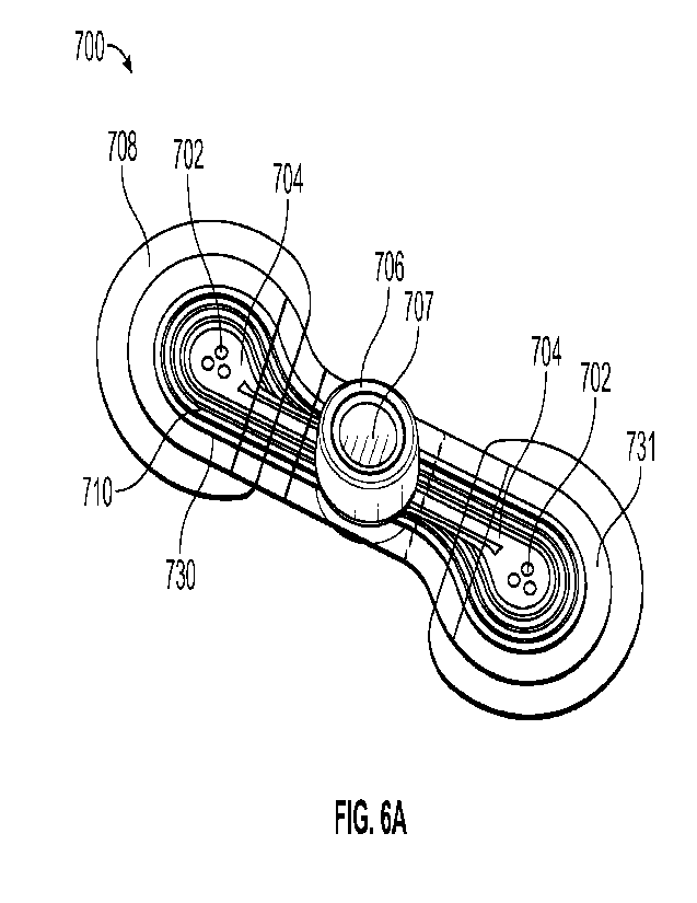
[0057] Figs. 6A-6H illustrate various views of embodiments of
a physiological
monitoring device. Fig. 6A depicts a perspective view, Fig. 6B shows a top
view, Figure 6C shows
a bottom view, and Figure 6D1 depicts a side view. Figure 6D2 depicts a side
view of a ridge
configured for sealing the top and bottom portions of the housing. Figures 6E
and 6F show a
bottom and a top view of the physiological monitoring device with the layers
illustrated
transparently, to provide visualization through the device. Figs. 6G and 6H
illustrate exploded
views of the various components of the physiological monitoring device.
[0058] Figs. 7A-F schematically illustrates the profile of a
substrate layer of a flexible
body having hinge lines between which the flexible body is configured to
float. Figures 7B-7D
schematically illustrate various examples of configurations of adhesive layers
comprising bridges
designed to be coupled to the flexible body and to extend underneath the
housing. Fig. 7E
schematically illustrates bottom views of physiological monitoring devices
comprising a single
adhesive layer having a -headphone" shaped configuration and comprising a
bridge portion. Fig.
7F depicts an embodiment of a wing shape.
[0059] Figs. 8A-8J schematically illustrate embodiments of a
physiological monitoring
device having a rigid body and traces coupled to the top surface of a flexible
body. Figs. 8A-8J
illustrate the various steps of assembling the physiological monitoring device
and/or replacing the
flexible body, including the adhesive layer, of the physiological monitoring
device.
[0060] Fig. 9 is a view of a top portion and a bottom portion
of a housing of the
physiological monitoring device, according to one embodiment.
[0061] Figs. 10A and 10B provide a perspective view of a
battery holder of the
physiological monitoring device, according to one embodiment.
[0062] Figs. 11A and 11B are cross sectional views of the
physiological monitoring
device, according to one embodiment.
[0063] Fig. 12 is an exploded view of the physiological
monitoring device including a
number of optional items, according to one embodiment.
[0064] Figs. 13A and 13B are perspective views of two people
wearing the
physiological monitoring device, illustrating how the device bends to conform
to body movement
and position, according to one embodiment.
[0065] Figs. 14A, 14B, 14C, 14D, 14E, and 14F illustrate
various steps for applying
the physiological monitor to a patient's body, according to one embodiment.
CA 03188325 2023- 2-3
WO 2022/032117
PCT/US2021/044976
[0066] Fig. 15 illustrates a schematic diagram of an
embodiment of a cardiac rhythm
inference service.
DETAILED DESCRIPTION OF EMBODIMENTS
[0067] The following description is directed to a number of
various embodiments. The
described embodiments, however, may be implemented and/or varied in many
different ways. For
example, the described embodiments may be implemented in any suitable device,
apparatus, or
system to monitor any of a number of physiological parameters. For example,
the following
discussion focuses primarily on long-term, patch-based cardiac rhythm
monitoring devices. In one
alternative embodiment, a physiological monitoring device may be used, for
example, for pulse
oximetry and diagnosis of obstructive sleep apnea. The method of using a
physiological
monitoring device may also vary. In some cases, a device may be worn for one
week or less, while
in other cases, a device may be worn for at least seven days and/or for more
than seven days, for
example between fourteen days and twenty-one days or even longer. Many other
alternative
embodiments and applications of the described technology are possible. Thus,
the following
description is provided for exemplary purposes only. Throughout the
specification, reference may
be made to the term "conformal." It will be understood by one of skill in the
art that the term
"conformal" as used herein refers to a relationship between surfaces or
structures where a first
surface or structure adapts to the contours of a second surface or structure.
[0068] Since abnormal heart rhythms or arrhythmias can often
be due to other, less
serious causes, a key challenge is to determine when any of these symptoms are
due to an
arrhythmia. Oftentimes, arrhythmias occur infrequently and/or episodically,
making rapid and
reliable diagnosis difficult. As mentioned above, currently, cardiac rhythm
monitoring is primarily
accomplished through the use of devices, such as Holter monitors, that use
short-duration (less
than 1 day) electrodes affixed to the chest. Wires connect the electrodes to a
recording device,
usually worn on a belt. The electrodes need daily changing and the wires are
cumbersome. The
devices also have limited memory and recording time. Wearing the device
interferes with patient
movement and often precludes performing certain activities while being
monitored, such as
bathing. Further, Holter monitors are capital equipment with limited
availability, a situation that
often leads to supply constraints and corresponding testing delays. These
limitations severely
hinder the diagnostic usefulness of the device, the compliance of patients
using the device, and the
11
CA 03188325 2023- 2-3
WO 2022/032117
PCT/US2021/044976
likelihood of capturing all important information. Lack of compliance and the
shortcomings of the
devices often lead to the need for additional devices, follow-on monitoring,
or other tests to make
a correct diagnosis.
[0069] Current methods to correlate symptoms with the
occurrence of arrhythmias,
including the use of cardiac rhythm monitoring devices, such as Holter
monitors and cardiac event
recorders, are often not sufficient to allow an accurate diagnosis to be made.
In fact, Holter
monitors have been shown to not lead to a diagnosis up to 90% of the time
("Assessment of the
Diagnostic Value of 24-Hour Ambulatory Electrocardiographic Monitoring", by DE
Ward et al.
Biotelemetry Patient Monitoring, vol. 7, published in 1980).
[0070] Additionally, the medical treatment process to actually
obtain a cardiac rhythm
monitoring device and initiate monitoring is typically very complicated. There
are usually
numerous steps involved in ordering, tracking, monitoring, retrieving, and
analyzing the data from
such a monitoring device. In most cases, cardiac monitoring devices used today
are ordered by a
cardiologist or a cardiac electrophysiologist (EP), rather than the patient's
primary care physician
(PCP). This is of significance since the PCP is often the first physician to
see the patient and
determine that the patient's symptoms could be due to an arrhythmia. After the
patient sees the
PCP, the PCP will make an appointment for the patient to see a cardiologist or
an EP. This
appointment is usually several weeks from the initial visit with the PCP,
which in itself leads to a
delay in making a potential diagnosis as well as increases the likelihood that
an arrhythmia episode
will occur and go undiagnosed. When the patient finally sees the cardiologist
or EP, a cardiac
rhythm monitoring device will usually be ordered. The monitoring period can
last 24 to 48 hours
(Holter monitor) or up to a month (cardiac event monitor or mobile telemetry
device). Once the
monitoring has been completed, the patient typically must return the device to
the clinic, which
itself can be an inconvenience. After the data has been processed by the
monitoring company or
by a technician on-site at a hospital or office, a report will finally be sent
to the cardiologist or EP
for analysis. This complex process results in fewer patients receiving cardiac
rhythm monitoring
than would ideally receive it.
[0071] To address some of these issues with cardiac
monitoring, the assignee of the
present application developed various embodiments of a small, long-term,
wearable, physiological
monitoring device. One embodiment of the device is the Zio0 Patch. Various
embodiments are
also described, for example, in U.S. Patent Numbers 8,150,502, 8,160,682
8,244,335, 8,560,046,
12
CA 03188325 2023- 2-3
WO 2022/032117
PCT/US2021/044976
8,538,503, 9,173,670, and 9,597,004, and U.S. Pat. Pub. No. 2018/0289274 Al,
the full disclosures
of which are hereby incorporated herein by reference. Generally, the
physiological patch-based
monitors described in the above references fit comfortably on a patient's
chest and are designed to
be worn for at least one week and typically two to three weeks. The monitors
detect and record
cardiac rhythm signal data continuously while the device is worn, and this
cardiac rhythm data is
then available for processing and analysis.
[0072] These smaller, long-term, patch-based physiological
monitoring devices
provide many advantages over prior art devices. At the same time, further
improvements are
desired. One of the most meaningful areas for improvement is to offer more
timely notice of critical
arrhythmias to managing clinicians. The hallmark of these initial embodiments
was that ¨ for
reasons of performance, compliance and cost ¨ the device only recorded
information during the
extended wear period, with analysis and reporting occurring after the
recording completed. Thus,
a desirable improvement would be to add the capability of either real-time or
timely analysis of
the collected rhythm information. While diagnostic monitors with such timely
reporting
capabilities currently exist, they require one or more electrical components
of the system to be
either regularly recharged or replaced. These actions are associated with
reduced patient
compliance and, in turn, reduced diagnostic yield. As such, a key area of
improvement is to develop
a physiologic monitor that can combine long-term recording with timely
reporting without
requiring battery recharging or replacement.
[0073] Patient compliance and device adhesion performance are
two factors that
govern the duration of the ECG record and consequently the diagnostic yield.
Compliance can be
increased by improving the patient's wear experience, which is affected by
wear comfort, device
appearance, and the extent to which the device impedes the normal activities
of daily living. Given
that longer ECG records provide greater diagnostic yield and hence value,
improvements to device
adhesion and patient compliance are desirable.
[0074] Signal quality is important throughout the duration of
wear, but may be more
important where the patient marks the record, indicating an area of
symptomatic clinical
significance. Marking the record is most easily enabled through a trigger
located on the external
surface of the device. However, since the trigger may be part of a skin-
contacting platform with
integrated electrodes, the patient can introduce significant motion artifacts
when feeling for the
13
CA 03188325 2023- 2-3
WO 2022/032117
PCT/US2021/044976
trigger. A desirable device improvement would be a symptom trigger that can be
activated with
minimal addition of motion artifact.
[0075] Further, it is desirable for the device to be simple
and cost effective to
manufacture, enabling scalability at manufacturing as well as higher quality
due to repeatability in
process. Simplicity of manufacture can also lead to ease of disassembly, which
enables the
efficient recovery of the printed circuit board for quality-controlled reuse
in another device.
Efficient reuse of this expensive component can be important for decreasing
the cost of the
diagnostic monitor.
[0076] There remain clinical scenarios where still longer-
duration and lower-cost
solutions may be a valuable addition to a portfolio of cardiac ambulatory
monitoring options.
Inspiration for a potential solution to these needs can be found in the
continuous heart rate sensing
functionality that is increasingly being incorporated in a variety of consumer
health and fitness
products, including smart watches and wearable fitness bands. Although
continuous heart rate data
can be used to provide the user with information about their general fitness
levels, it is more both
more challenging and valuable to use this data to provide meaningful
information related to their
health and wellness. For example, the ability to detect potential arrhythmias
from continuous heart
rate data would enable consumer devices incorporating heart rate sensing
functionality to serve as
potential screening tools for the early detection of cardiac abnormalities.
Such an approach could
be clinically valuable in providing a long-term, cost-effective screening
method for at-risk
populations, for example, heart failure patients at risk for Atrial
Fibrillation. Alternatively, this
monitoring approach could be helpful in the long-term titration of therapeutic
drug dosages to
ensure efficaciousness while reducing side effects, for example, in the
management of Paroxysmal
Atrial Fibrillation. Beyond cardiac arrhythmia detection, the appropriate
analysis of heart rate
information could also yield insight into sleep and stress applications.
[0077] Long-term ambulatory monitoring with a physiologic
device, such as an
adhesive patch, has a number of clinical applications, particularly when
timely information about
the occurrence and duration of observed arrhythmias can be provided during the
monitoring
period. In terms of prevalence, particularly as driven by an aging population,
efficiently detecting
Atrial Fibrillation (AF) remains the most significant monitoring need. This
need is not just evident
for patients presenting with symptoms, but also given the increased risk of
stroke associated with
this arrhythmia for broader, population-based monitoring of asymptomatic AF in
individuals at
14
CA 03188325 2023- 2-3
WO 2022/032117
PCT/US2021/044976
risk due to one or more factors of advanced age, the presence of chronic
illnesses like Heart
Disease, or even the occurrence of surgical procedures. For the latter group,
both perioperative and
post-procedure monitoring can be clinically valuable, and not just for
procedures targeted at
arrhythmia prevention (for example, the MAZE ablation procedure, or hybrid
endo and epicardi al
procedures, both for treatment of AF), but also for general surgeries
involving anesthesia. For
some applications, the goal of ambulatory monitoring for Atrial Fibrillation
will sometimes be
focused on the simple binary question of whether AF did occur in a given time
period. For
example, monitoring a patient following an ablation procedure will typically
seek to confirm
success, typically defined as the complete lack of AF occurrence. Likewise,
monitoring a patient
post-stroke will be primarily concerned with evaluating the presence of Atrial
Fibrillation.
[0078] However, even in those scenarios, if AF occurs, it may
be clinically meaningful
to evaluate additional aspects to better characterize the occurrence, such as
daily burden (% of time
in AF each day), and duration of episodes (expressed, for example, as a
histogram of episode
duration, or as the percentage of episodes that extend beyond a specified
limit, say six minutes),
both either in absolute terms or in comparison to prior benchmarks (for
example, from a baseline,
pre-procedure monitoring result). Indeed, measuring daily AF burden.
evaluating AF episode
duration, and reviewing AF occurrence during sleep and waking periods, and
evaluating the
presence of AF in response to the degree of a patient's physical movement can
be important in a
variety of clinical scenarios, including evaluating the effectiveness of drug-
based treatment for this
arrhythmia.
[0079] Making this information available in a timely manner
during the monitoring
period could allow the managing physician to iteratively titrate treatment,
for example, by
adjusting the dosage and frequency of a novel oral anticoagulant drug (NOAC)
until management
was optimized. A further example of this management paradigm is for the
patient to he notified of
asymptomatic AF ¨ either directly by the device through audible or vibration-
based alert, through
notification from an application connected to the device, or via phone, email
or text-message
communication from the managing clinician ¨ for the timely application of a
"pill in the pocket"
for AF management.
[0080] The theme of timely management and/or intervention is
certainly evident in
situations where clinically significant arrhythmias are observed, for example,
asymptomatic
second-degree and complete Heart Block, extended pauses, high-rate
supraventricular
CA 03188325 2023- 2-3
WO 2022/032117
PCT/US2021/044976
tachycardias, prolonged ventricular tachycaridas, and ventricular
fibrillation. For example, the
clinical scenario where an extended pause or complete heart block causes
Syncope is a particularly
significant case where the availability of a timely and dependable monitoring
method could reduce
or even eliminate the need for in-hospital monitoring of at-risk patients. The
theme can also extend
to more subtle changes in morphology, for example, QT prolongation in response
to medications,
which has been shown to have significant cardiac safety implications. Timely
awareness of such
prolongation could lead, for example, to early termination of clinical studies
evaluating drug safety
and effectiveness or, alternatively, to adjusting the dosage or frequency as a
means to eliminate
observed prolongation.
Physiological Monitoring Devices
[0081] Referring to Figures lA and 1B, perspective and
exploded profile views of one
embodiment of a physiological monitoring device 100 are provided. As seen in
Figure 1A,
physiological monitoring device 100 may include a flexible body 110 coupled
with a watertight,
housing 115. As will be understood by one of skill in the art, the housing as
described herein and
throughout this specification, may be constructed from rigid or flexible
materials, thereby
rendering the housing rigid, such as to resist deformation or soft such as to
flex and/or deform with
force. Flexible body 110 (which may be referred to as "flexible substrate" or
"flexible construct")
typically includes two wings 130, 131, which extend laterally from housing
115, and two flexible
electrode traces 311, 312, each of which is embedded in one of wings 130, 131.
Each electrode
trace 311, 312 is coupled, on the bottom surface of flexible body 110, with a
flexible electrode
(not visible in Figure 1A). The electrodes are configured to sense heart
rhythm signals from a
patient to which monitoring device 100 is attached. Electrode traces 311, 312
then transmit those
signals to electronics (not visible in Figure 1A) housed in housing 115.
Housing 115 also typically
contains a power source, such as one or more batteries.
[0082] The combination of a highly flexible body 110,
including flexible electrodes
and electrode traces 311, 312, with a very housing 115 may provide a number of
advantages. A
key advantage is high fidelity signal capture. The highly conformal and
flexible wings 130, 131,
electrodes and traces 311, 312 limit the transmission of external energy to
the electrode-skin
interface. If motion is imparted to the housing 115, for example, the system
of conformal adhesion
to the skin limits the extent to which that motion affects the monitored
signal. Flexible electrode
16
CA 03188325 2023- 2-3
WO 2022/032117
PCT/US2021/044976
traces 311, 312 generally may help provide conformal contact with the
subject's skin and may help
prevent electrodes 350 (electrodes 350 are not visible in Figure 1, but are
visible in Figure 6A
described below) from peeling or lifting off of the skin, thereby providing
strong motion artifact
rejection and better signal quality by minimizing transfer of stress to
electrodes 350. Furthermore,
flexible body 110 includes a configuration and various features that
facilitate comfortable wearing
of device 100 by a patient for fourteen (14) days or more without removal.
Housing 115, which
typically does not adhere to the patient in the embodiments described herein,
includes features that
lend to the comfort of device 100. Hinge portions 132 are relatively thin,
even more flexible
portions of flexible body 110. They allow flexible body 110 to flex freely at
the area where it is
joined to housing 115. This flexibility enhances comfort, since when the
patient moves, housing
115 can freely lift off of the patient's skin. Electrode traces 311, 312 are
also very thin and flexible,
to allow for patient movement without signal distortion.
[0083] Referring now to Figure 1B, a partially exploded view
of physiological
monitoring device 100 illustrates component parts that make up, and that are
contained within,
housing 115 in greater detail. In this embodiment, housing 115 includes an
upper housing member
140, which detachably couples with a lower housing member 145. Sandwiched
between upper
housing member 140 and lower housing member 145 are an upper gasket 370, and a
lower gasket
360 (not visible on Figure 1B but just below upper gasket 370). Gaskets 370,
360 help make
housing 115 watertight when assembled. A number of components of monitoring
device 100 may
be housed between upper housing member 140 and lower housing member 145. For
example, in
one embodiment, housing 115 may contain a portion of flexible body 110, a
printed circuit board
assembly (PCBA) 120, a battery holder 150, and two batteries 160. Printed
circuit board assembly
120 is positioned within housing 115 to contact electrode traces 311, 312 and
batteries 160. In
various embodiments, one or more additional components may be contained within
or attached to
housing 115. Some of these optional components are described further below, in
reference to
additional drawing figures.
[0084] Battery holder 150, according to various alternative
embodiments, may hold
two batteries (as in the illustrated embodiment), one battery, or more than
two batteries. In other
alternative embodiments, other power sources may be used. In the embodiment
shown, battery
holder 150 includes multiple retain tabs 153 for holding batteries 160 in
holder 150. Additionally,
battery holder 150 includes multiple feet 152 to establish correct spacing of
batteries 160 from the
17
CA 03188325 2023- 2-3
WO 2022/032117
PCT/US2021/044976
surface of PCBA 120 and ensure proper contact with spring fingers and/or
contacts 235 and 236.
Spring fingers 235 and 236 are used in this embodiment rather than soldering
batteries 160 to
PCBA 120. Although soldering may be used in alternative embodiments, one
advantage of spring
fingers 235 and 236 is that they allow batteries 160 to be removed from PCBA
120 and holder 150
without damaging either of those components, thus allowing for multiple reuses
of both.
Eliminating solder connections also simplifies and speeds up assembly and
disassembly of
monitoring device 100.
[0085] In some embodiments, upper housing member 140 may act
as a patient event
trigger. When a patient is wearing physiological monitoring device 100 for
cardiac rhythm
monitoring, it is typically advantageous for the patient to be able to
register with device 100 (for
example, log into the device's memory) any cardiac events perceived by the
patient. If the patient
feels what he/she believes to be an episode of heart arrhythmia, for example,
the patient may
somehow trigger device 100 and thus provide a record of the perceived event.
In some
embodiments, trigger of perceived events by the patient may initiate
transmission of data
associated with the triggered event. In some embodiments, trigger of perceived
events may simply
mark a continuous record with the location of the triggered event. In some
embodiments, both
transmission of associated data as well as marking of the continuous record
may occur. At some
later time, the patient's recorded symptom during the perceived event could be
compared with the
patient's actual heart rhythm, recorded by device 100, and this may help
determine whether the
patient's perceived events correlate with actual cardiac events. One problem
with patient event
triggers in currently available wearable cardiac rhythm monitoring devices,
however, is that a
small trigger may be hard to find and/or activate, especially since the
monitoring device is typically
worn under clothing. Additionally, pressing a trigger button may affect the
electronics and/or the
electrodes on the device in such a way that the recorded heart rhythm signal
at that moment is
altered simply by the motion caused to the device by the patient triggering.
For example, pressing
a trigger may jar one or both of the electrodes in such a way that the
recorded heart rhythm signal
at that moment appears like an arrhythmia, even if no actual arrhythmia event
occurred.
Additionally, there is a chance that the trigger may be inadvertently
activated, for instance while
sleeping or laying on the monitoring device.
[0086] In the embodiment shown in Figures lA and 1B, however,
housing 115 is
sufficiently rigid, and flexible body 110 is sufficiently flexible, that
motion applied to housing 115
18
CA 03188325 2023- 2-3
WO 2022/032117
PCT/US2021/044976
by a patient may rarely or ever cause an aberrant signal to be sensed by the
electrodes. In this
embodiment, the central portion of upper housing member 140 is slightly
concave and, when
pressed by a patient who is wearing device 100, this central portion depresses
slightly to trigger a
trigger input on PCBA 120. Because the entire upper surface of housing 115
acts as the patient
event trigger, combined with the fact that it is slightly concave, it will
generally be quite easy for
a patient to find and push down the trigger, even under clothing.
Additionally, the concave nature
of the button allows it to be recessed which protects it from inadvertent
activations. Thus, the
present embodiment may alleviate some of the problems encountered with patient
event triggers
on currently available heart rhythm monitors. These and other aspects of the
features shown in
Figures lA and 1B will be described in further detail below.
[0087] Referring now to the embodiments in Figures 2A and 2B,
printed circuit board
assembly 120 (or PCBA) may include a top surface 220, a bottom surface 230, a
patient trigger
input 210 and spring contacts 235, 236, and 237. Printed circuit board
assembly 120 may be used
to mechanically support and electrically connect electronic components using
conductive
pathways, tracks or electrode traces 311, 312. Furthermore, because of the
sensitive nature of
PCBA 120 and the requirement to mechanically interface with rigid housing 115,
it is beneficial
to have PCBA 120 be substantially rigid enough to prevent unwanted deflections
which may
introduce noise or artifact into the ECG signal. This is especially possible
during patient trigger
activations when a force is transmitted through rigid housing 115 and into
PCBA 120. One way to
ensure rigidity of the PCBA is in some embodiments, to ensure that the
thickness of the PCBA is
relatively above a certain value. For example, a thickness of at least about
0.08 cm is desirable
and, more preferably, a thickness of at least about 0.17 cm is desirable. In
this application, PCBA
120 may also be referred to as, or substituted with, a printed circuit board
(PCB), printed wiring
board (PWB), etched wiring board, or printed circuit assembly (PCA). In some
embodiments, a
wire wrap or point-to-point construction may be used in addition to, or in
place of, PCBA 120.
PCBA 120 may include analog circuits and digital circuits.
[0088] Patient trigger input 210 may be configured to relay a
signal from a patient
trigger, such as upper housing member 140 described above, to PCBA 120. For
example, patient
trigger input 210 may be a PCB switch or button that is responsive to pressure
from the patient
trigger (for example, the upper surface of upper housing member portion 140).
In various
embodiments, patient trigger input 210 may be a surface mounted switch, a
tactile switch, an LED
19
CA 03188325 2023- 2-3
WO 2022/032117
PCT/US2021/044976
illuminated tactile switch, or the like. In some embodiments, patient trigger
input 210 may also
activate an indicator, such as an LED. Certain embodiments may involve a
remotely located trigger
such as on a separate device or as a smart phone app.
[0089] One important challenge in collecting heart rhythm
signals from a human or
animal subject with a small, two-electrode physiological monitoring device
such as device 100
described herein, is that having only two electrodes can sometimes provide a
limited perspective
when trying to discriminate between artifact and clinically significant
signals. For example, when
a left-handed patient brushes her teeth while wearing a small, two-electrode
physiological
monitoring device on her left chest, the tooth brushing may often introduce
motion artifact that
causes a recorded signal to appear very similar to Ventricular Tachycardia, a
serious heart
arrhythmia. Adding additional leads (and, hence, vectors) is the traditional
approach toward
mitigating this concern, but this is typically done by adding extra wires
adhered to the patient's
chest in various locations, such as with a Holter monitor. This approach is
not consistent with a
small, wearable, long term monitor such as physiological monitoring device
100.
[0090] An alternate approach to the problem described above is
to provide one or more
additional data channels to aid signal discrimination. In some embodiments,
for example, device
100 may include a data channel for detecting patch motion. In certain
embodiments, an
accelerometer or other suitable device may provide patch motion by simply
analyzing the change
in magnitude of a single axis measurement, or alternatively of the combination
of all three axes.
The accelerometer may record device motion at a sufficient sampling rate to
allow algorithmic
comparison of its frequency spectrum with that of the recorded ECG signal. If
there is a match
between the motion and recorded signal, it is clear that the device recording
in that time period is
not from a clinical (for example, cardiac) source, and thus that portion of
the signal can be
confidently marked as artifact. This technique may be particularly useful in
the tooth brushing
motion example aforementioned, where the rapid frequency of motion as well as
the high
amplitude artifact is similar to the heart rate and morphology, respectively,
of a potentially life-
threatening arrhythmia like Ventricular Tachycardia. Other suitable devices
described herein this
section and elsewhere in the specification may also be utilized to provide
motion information.
[0091] In some embodiments, using the magnitude of all three
axes for such an analysis
would smooth out any sudden changes in values due to a shift in position
rather than a change in
activity. In other embodiments, there may be some advantage in using a
specific axis of
CA 03188325 2023- 2-3
WO 2022/032117
PCT/US2021/044976
measurement such as along the longitudinal axis of the body to focus on a
specific type of artifact
introduced by upward and downward movements associated with walking or
running. In a similar
vein, the use of a gyroscope in conjunction with the accelerometer may provide
further resolution
as to the nature of the motion experienced. While whole body movements may be
sufficiently
analyzed with an accelerometer on its own, specific motion of interest such as
rotational motion
due to arm movement is sufficiently complex that an accelerometer alone might
not be able to
distinguish.
[0092] In addition to detecting motion artifact, an
accelerometer tuned to the dynamic
range of human physical activities may provide activity levels of the patient
during the recording,
which can also enhance accuracy of algorithmic true arrhythmia detection.
Given the single-lead
limitation of device 100, arrhythmias that require observation of less
prominent waves (for
example P-wave) in addition to rate changes such as Supraventricular
Tachycardia pose challenges
to both computerized algorithms as well as the trained human eye. This
particular arrhythmia is
also characterized by the sudden nature of its onset, which may be more
confidently discriminated
from a non-pathological Sinus Tachycardia if a sudden surge in the patient's
activity level is
detected at the same time as the increase in heart rate. Broadly speaking, the
provision of activity
information to clinical professionals may help them discriminate between
exercise-induced
arrhythmia versus not. As with motion artifact detection, a single-axis
accelerometer measurement
optimized to a particular orientation may aid in more specifically determining
the activity type
such as walking or running. This additional information may help explain
symptoms more
specifically and thereby affect the subsequent course of therapeutic action.
[0093] In certain embodiments, an accelerometer with 3 axes
may confer advantages
beyond what magnitude of motions can provide. When the subject is not rapidly
moving, 3-
dimensional accelerometer readings may approximate the tilt of PCB A 120, and
therefore body
orientation relative to its original orientation. The original body
orientation can be assumed to be
in either an upright or supine position which is required for appropriate
positioning and application
of the device to the body. This information may aid in ruling out certain
cardiac conditions that
manifest as beat-to-beat morphology changes, such as cardiac altemans where
periodic amplitude
changes are observed, often in heart failure cases. Similar beat-to-beat
morphology changes are
observable in healthy subjects upon shift in body position due to the shift in
heart position relative
to the electrode vector, for example from an upright to a slouching position.
By design, the single-
21
CA 03188325 2023- 2-3
WO 2022/032117
PCT/US2021/044976
channel device 100 does not have an alternate ECG channel to easily rule out
potential pathological
shifts in morphology, however, correlation with shifts in body orientation
will help explain these
normal changes and avoid unnecessary treatment due to false diagnosis.
[0094] In other embodiments, the accelerometer may also be
used as a sleep indicator,
based on body orientation and movement. When presenting clinical events (for
example, pauses),
it is diagnostically helpful to be able to present information in a manner
that clearly separates
events that occurred during sleep from those during waking hours. In fact,
certain algorithms such
as for ECG-derived respiratory rate only make sense to run when the patient is
in a relatively
motionless state and therefore subtle signal modulation introduced by chest
movement due to
breathing is observable. Respiratory rate information is useful as one channel
of information
necessary to detect sleep apnea in certain patient populations.
[0095] In certain embodiments, the accelerometer may also be
used to detect free-falls,
such as fainting. With an accelerometer, device 100 may be able to mark
fainting (syncope) and
other free-fall events without relying on patient trigger. In some
embodiments, such free-fall event
triggers may initiate transmission of associated data. In order to allow
timely detection of such
critical events, yet considering the battery and memory limitations of a
small, wearable device
such as device 100, acquisition of accelerometer readings may be done in
bursts, where only
interesting information such as a potential free fall is written to memory at
a high sampling rate.
An expansion of this event-trigger concept is to use specific tapping motions
on device 100 as a
patient trigger instead of or in conjunction with the button previously
described. The use and
detection of multiple types of tapping sequences may provide better resolution
and accuracy into
what exactly the patient was feeling, instead of relying on the patient to
manually record their
symptom and duration in a trigger log after the fact. An example of such added
resolution is to
indicate the severity of the symptom by the number of sequential taps.
[0096] Alternatively, in other embodiments, optical sensors
may be used to distinguish
between device motion and patient body motion. Further, in additional
embodiments, the device
may not require a button or trigger. In still more embodiments, suitable
devices described herein
this section or elsewhere in the specification may also be used.
[0097] Another optional data channel that may be added to
physiological monitoring
device 100 is a channel for detecting flex and/or bend of device 100. In
various embodiments, for
example, device 100 may include a strain gauge, piezoelectric sensor or
optical sensor to detect
22
CA 03188325 2023- 2-3
WO 2022/032117
PCT/US2021/044976
motion artifact in device 100 itself and thus help to distinguish between
motion artifact and cardiac
rhythm data. Yet another optional data channel for device 100 may be a channel
for detecting heart
rate. For example, a pulse oximeter, microphone or stethoscope may provide
heart rate
information. Redundant heart rate data may facilitate discrimination of ECG
signals from artifact.
This is particularly useful in cases where arrhythmia such as Supraventricular
Tachycardia is
interrupted by artifact, and decisions must be made whether the episode was
actually multiple
shorter episodes or one sustained episode. Another data channel may be
included for detecting
ambient electrical noise. For example, device 100 may include an antenna for
picking up
electromagnetic interference. Detection of electromagnetic interference may
facilitate
discrimination of electrical noise from real ECG signals. Any of the above-
described data channels
may be stored to support future noise discrimination or applied for immediate
determination of
clinical validity in real-time.
[0098] With reference now to the embodiments of Figures 3A and
3B, flexible body
110 is shown in greater detail. As illustrated in Figure 3A, flexible body 110
may include wings
130, 131, a thin border 133 (or "rim" or "edge") around at least part of each
wing 130, 131,
electrode traces 311, 312, and a hinge portion 132 (or "shoulder") at or near
a junction of each
wing 130, 131 with housing 115. Also shown in Figure 3A is upper gasket 370,
which is not
considered part of flexible body 110 for this description, but which
facilitates attachment of
flexible body 110 to housing 115.
[0099] Hinge portions 132 are relatively thin, even more
flexible portions of flexible
body 110. They allow flexible body 110 to flex freely at the area where it is
joined to housing 115.
This flexibility enhances comfort, since when the patient moves, housing 115
can freely lift off of
the patient's skin. Electrode traces 311, 312 are also very thin and flexible,
to allow for patient
movement without signal distortion. Borders 133 are portions of flexible body
110 that is thinner
than immediately adjacent portions and that provide for a smooth transition
from flexible body
110 to a patient's skin, thus preventing edge-lift and penetration of dirt or
debris below flexible
body 110.
[0100] As shown in greater detail in Figure 3B, flexible body
110 may include multiple
layers. As mentioned previously, in some embodiments, upper gasket 370 and
lower gasket 360
are not considered part of flexible body 110 for the purposes of this
description but are shown for
completeness of description. This distinction is for ease of description only,
however, and should
23
CA 03188325 2023- 2-3
WO 2022/032117
PCT/US2021/044976
not be interpreted to limit the scope of the described embodiments. Flexible
body 110 may include
a top substrate layer 300, a bottom substrate layer 330, an adhesive layer
340, and flexible
electrodes 350. Top and bottom substrate layers 300, 330 may be made of any
suitable, flexible
material, such as one or more flexible polymers. Suitable flexible polymers
can include, but are
not limited to, polyurethane, polyethylene, polyester, polypropylene, nylon,
teflon and carbon
impregnated vinyl. The material of substrate layers 300, 330 may be selected
based on desired
characteristics. For example, the material of substrate layers 300, 330 may be
selected for
flexibility, resilience, durability, breathability, moisture transpiration,
adhesion and/or the like. In
one embodiment, for example, top substrate layer 300 may be made of
polyurethane, and bottom
substrate layer 330 may be made of polyethylene or alternatively polyester. In
other embodiments,
substrate layers 300, 330 may be made of the same material. In yet another
embodiment, substrate
layer 330 may contain a plurality of perforations in the area over adhesive
layer 340 to provide for
even more breathability and moisture transpiration. In various embodiments,
physiological
monitoring device 100 may be worn continuously by a patient for as many as 14-
21 days or more,
without removal during the time of wear and with device 100 being worn during
showering,
exercising and the like. Thus, the material(s) used and the thickness and
configuration of substrate
layers 300, 330 affect the function of physiological monitoring device 100. In
some embodiments,
the material of substrate layers 300, 330 acts as an electric static discharge
(ESD) barrier to prevent
arcing.
[0101] Typically, top and bottom substrate layers 300, 330 are
attached to one another
via adhesive placed on one or both layers 300, 330. For example, the adhesive
or bonding
substance between substrate layers 300, 330 may be an acrylic-based, rubber-
based, or silicone-
based adhesive. In other alternative embodiments, flexible body 110 may
include more than two
layers of flexible material.
[0102] In addition to the choice of material(s), the
dimensions¨thickness, length and
width¨of substrate layers 300, 330 may be selected based on desired
characteristics of flexible
body 110. For example, in various embodiments, the thickness of substrate
layers 300, 330 may
be selected to give flexible body 110 an overall thickness of between about
0.1 mm to about 1.0
mm. According to various embodiments, flexible body 110 may also have a length
of between
about 7 cm and 15 cm and a width of about 3 cm and about 6 cm. Generally,
flexible body 110
will have a length sufficient to provide a necessary amount of separation
between electrodes 350.
24
CA 03188325 2023- 2-3
WO 2022/032117
PCT/US2021/044976
For example, in one embodiment a distance from the center of one electrode 350
to the center of
the other electrode 350 should be at least about 6.0 cm and more preferably at
least about 8.5 cm.
This separation distance may vary, depending on the application. In some
embodiments, substrate
layers 300, 330 may all have the same thickness. Alternatively, the two
substrate layers 300, 330
may have different thicknesses.
[0103] As mentioned above, hinge portions 132 allow the rigid
housing 115 to lift away
from the patient while flexible body 110 remains adhered to the skin. The
functionality of hinge
portions 132 is critical in allowing the device to remain adhered to the
patient throughout various
activities that may stretch and compress the skin. Furthermore, hinge portions
132 allow for
significantly improved comfort while wearing the device. Generally, hinge
portions 132 will be
sufficiently wide enough to provide adequate lift of rigid housing 115 without
creating too large
of a peel force on flexible body 110. For example, in various embodiments, the
width of hinge
portion 132 should be at least about 0.25 cm and more preferably at least
about 0.75 cm.
[0104] Additionally, the shape or footprint of flexible body
110 may be selected based
on desired characteristics. As seen in Figure 3A, wings 130, 131 and borders
133 may have
rounded edges that give flexible body 110 an overall "peanut" shape. However,
wings 130, 131
can be formed in any number of different shapes such as rectangles, ovals,
loops, or strips. In the
embodiment shown in Figures 3A and 3B, the footprint top substrate layer 300
is larger than the
footprint of bottom substrate layer 330, with the extension of top substrate
layer 300 forming
borders 133. Thus, borders 133 are made of the same polyurethane material that
top layer 300 is
made of. Borders 133 are thinner than an adjacent portion of each wing 130,
131, since they
includes only top layer 300. The thinner, highly compliant rim and/or border
133 will likely
enhance adherence of physiologic monitoring device 100 to a patient, as it
provides a transition
from an adjacent, slightly thicker portion of wings 130, 131 to the patient's
skin and thus helps
prevent the edge of the flexible body 110 from peeling up off the skin. Border
133 may also help
prevent the collection of dirt and other debris under flexible body 110, which
may help promote
adherence to the skin and also enhance the aesthetics of the flexible body
110. In some
embodiments, the border 133 may comprise a width (e.g., from an outer edge of
the border 133 to
an inner edge of the border 133) of at least about 3 mm, 6 mm, 9 mm, 12 mm, or
15 mm. In
alternative embodiments, the footprint of substrate layers 300, 330 may be the
same, thus
eliminating borders 133.
CA 03188325 2023- 2-3
WO 2022/032117
PCT/US2021/044976
[0105] While the illustrated embodiments of Figures 1A-3B
include only two wings
130, 131, which extend from housing 115 in approximately opposite directions
(for example, at a
180-degree angle relative to each other), other configurations are possible in
alternative
embodiments. For example, in some embodiments, wings 130, 131 may be arranged
in an
asymmetrical orientation relative to one another and/or one or more additional
wings may be
included. As long as sufficient electrode spacing is provided to permit
physiological signal
monitoring, and as long as wings 130. 131 are configured to provide extended
attachment to the
skin, any suitable configuration and number of wings 130, 131 and electrode
traces 311, 312 may
be used. The embodiments described above have proven to be advantageous for
adherence, patient
comfort and accuracy of collected heart rhythm data, but in alternative
embodiments it may be
possible to implement alternative configurations.
[0106] Adhesive layer 340 is an adhesive that is applied to
two portions of the bottom
surface of bottom substrate layer 330, each portion corresponding to one of
wings 130, 131.
Adhesive layer 340 thus does not extend along the portion of bottom substrate
layer 330 upon
which housing 115 is mounted. Adhesive layer 340 may be made of any suitable
adhesive,
although certain adhesives have been found to be advantageous for providing
long term adhesion
to patient skin with relative comfort and lack of skin irritation. For
example, in one embodiment,
adhesive layer 340 is a hydrocolloid adhesive. In another embodiment, the
adhesive layer 340 is
comprised of a hydrocolloid adhesive that contains naturally-derived or
synthetic absorbent
materials which take up moisture from the skin during perspiration.
[0107] With reference now to Figure 3B, each of the two
portions of adhesive layer
340 includes a hole, into which one of electrodes 350 fits. Electrodes 350 are
made of flexible
material to further provide for overall conformability of flexible body 110.
In one embodiment,
for example, flexible electrodes 350 may be made of a hydrogel. Electrodes 350
generally provide
conformal, non-irritating contact with the skin to provide enhanced electrical
connection with the
skin and reduce motion artifact. In some embodiments, hydrogel electrodes 350
may be punched
into adhesive layer 340, thus forming the holes and filling them with hydrogel
electrodes 350. In
one alternative embodiment, electrodes 350 and adhesive 340 may be replaced
with an adhesive
layer made of a conductive material, such that the entire adhesive layer on
the underside of each
wing 130, 131 acts as an electrode. Such an adhesive layer may include a
hybrid
adhesive/conductive substance or adhesive substance mixed with conductive
elements or particles.
26
CA 03188325 2023- 2-3
WO 2022/032117
PCT/US2021/044976
For example, in one embodiment, such an adhesive layer may be a hybrid of a
hydrogel and a
hydrocolloid adhesive. Housing 115 of Figure 1A also protects the electronics
and power source
contained in the housing and/or the PCBA 120, enhances the ability of a
patient to provide an input
related to a perceived cardiac event, and allows for simple manufacturing and
reusability of at least
some of the contents of housing 115. These and other features of physiological
monitoring device
100 are described in greater detail below.
[0108] As discussed above, in some embodiments, adhesive layer
340 may cover a
portion of the underside of lower substrate layer 330, such that at least a
portion of the bottom side
of flexible body 110 does not include adhesive layer 340. As seen in Figure
3A, hinges 132 may
be formed in the flexible body 110 as portions of each wing 130, 131 on which
adhesive layer 340
is not applied. Hinge portions 132 are generally located at or near the
junction of flexible body 110
with housing 115, and thus provide for flexing of device 100 to accommodate
patient movement.
In some embodiments, hinge portions 132 may have a width that is less than
that of adjacent
portions of wings 130, 131, thus giving device 100 its "peanut" shape
mentioned above. As shown
in Figure 8, as a subject moves, device 100 flexes along with patient
movement. Device flexion
may be severe and is likely to occur many times during long term monitoring.
Hinge portions 132
may allow for dynamic conformability to the subject, while the rigidity of
housing 115 may allow
housing 115 to pop up off the patient's skin during device flexion, thus
preventing peeling of the
device 100 off of the skin at its edge.
[0109] Flexible body 110 further includes two electrode traces
311, 312 sandwiched
between upper substrate layer 300 and lower substrate layer 330. Each
electrode trace 311, 312
may include an electrode interface portion 310 and an electrocardiogram
circuit interface portion
313. As illustrated in the embodiments of Figures 3C and 3D, ECG circuit
interface portions 313
are in physical contact with spring fingers 237 and provide electrical
communication with PCBA
120 when device 100 or zoomed-in device portion 101 is assembled. Electrode
interface portions
310 contact hydrogel electrodes 350. Thus, electrode traces 311, 312 transmit
cardiac rhythm
signals (and/or other physiological data in various embodiments) from
electrodes 350 to PCBA
120.
[0110] The material and thickness of electrode traces 311, 312
are important for
providing a desired combination of flexibility, durability and signal
transmission. For example, in
one embodiment, electrode traces 311, 312 may include a combination of silver
(Ag) and silver
27
CA 03188325 2023- 2-3
WO 2022/032117
PCT/US2021/044976
chloride (AgC1). The silver and silver chloride may be disposed in layers. For
example, one
embodiment of electrode traces 311, 312 may include a top layer of silver, a
middle layer of carbon
impregnated vinyl, and a bottom (patient-facing) layer of silver chloride. In
another embodiment,
both top and bottom layers of electrode traces 311, 312 may be made of silver
chloride. In one
embodiment, the top and bottom layers may be applied to the middle layer in
the form of silver
ink and silver chloride ink, respectively. In an alternative embodiment, each
electrode trace may
include only two layers, such as a top layer of silver and a bottom layer of
silver chloride. In
various embodiments, the material of a bottom layer of each electrode trace
311, 312, such as
AgC1, may be selected to match the chemistry of the hydrogel electrodes 350
and create a half-cell
with the body of the subject.
[0111] The thickness of the electrode traces 311, 312 may be
selected to optimize any
of a number of desirable properties. For example, in some embodiments, at
least one of the layers
of electrode traces 311, 312 can be of a sufficient thickness to minimize or
slow depletion of the
material from an anode/cathode effect over time. Additionally, the thickness
may be selected for
a desired flexibility, durability and/or signal transmission quality.
[0112] As mentioned above, in some embodiments, top gasket 370
and bottom gasket
360 may be attached upper substrate 300 and lower substrate 330 of flexible
body 110. Gaskets
360, 370 may be made of any suitable material, such as urethane, which
provides a water tight seal
between the upper housing member 140 and lower housing member 145 of housing
115. In one
embodiment, top gasket 370 and/or bottom gasket 360 may include an adhesive
surface. Figure
3E depicts yet another embodiment where top gasket 370 includes tabs 371 that
protrude away
from the profile of top housing member 140 while still being adhered to upper
substrate 300. The
tabs 371 cover a portion of electrode traces 311, 312 and provide a strain
relief for the traces at the
point of highest stress where the flexible body meets the housing.
[0113] Figures 4A-4E depict embodiments of adhesive layers
340, which can be
included as adhesive layers in the embodiments of Figures 1-3 and below in
Figures 5A-8D. Such
adhesive layers may be incorporated into any of the physiological monitoring
device embodiments
described herein this section or elsewhere in the specification. In certain
embodiments, the
adhesive layer 340 may be configured to optimize (e.g., maximize)
transpiration of moisture from
the surface of the patient's skin beneath a physiological monitoring device
such as depicted in
Figures 1A-B, 3A-3E, and 5A-8D, through the wings of said devices such as
described above as
28
CA 03188325 2023- 2-3
WO 2022/032117
PCT/US2021/044976
130, 131. Promoting transpiration of moisture through the physiological
monitoring device 100
(as shown in Figure 3E and elsewhere) may improve adhesion of the device 100
to the patient's
skin by preventing, reducing, and/or inhibiting the collection or pooling of
moisture between the
patient's skin and the bottom of the adhesive layer 340. Collection of
moisture between the
patient's skin and the bottom of the adhesive layer 340 may prevent, inhibit,
and/or interfere with
the adhesion of the adhesive layer 340 to the patient's skin, especially over
long durations. For
instance, the presence of excessive moisture may cause, promote, and/or
accelerate the peeling of
the edges of the adhesive layer 340 away from the patient's skin. Accordingly,
longer term
adhesion may be achieved by promoting the transpiration of moisture through
the device so that it
may be released (e.g., evaporate) into the atmosphere. The management of
moisture may be
particularly advantageous for when the patient sweats, such as during exercise
or during a hot
shower.
[0114] In particular embodiments, the adhesive layer 340 may
generally comprise a
top surface adhered to a bottom surface of the bottom substrate layer 330
(such as shown in Figures
3B and elsewhere) or another support layer and a bottom surface configured to
be adhered to the
patient's skin. The top surface may generally overlap the bottom surface,
and/or the top and
bottom surfaces of the adhesive layer 340 may define an adhesion area or
surface area that extends
in a horizontal plane to a peripheral edge of the adhesive layer 340. The
adhesive layer 340 may
have a vertical thickness extending from the bottom surface to the top
surface. The thickness may
be relatively uniform across the adhesion area. In some embodiments, the
adhesive layer 340 may
comprise a plurality of channels 341 connecting the bottom surface of the
adhesion layer 340 to
the top surface and/or the peripheral edge of the adhesive layer 340. The
channels 341 may be
formed as hollow voids within the adhesive layer 340. The cumulative surface
area of the channels
341 where the channels 341 interface the skin of the subject may, in some
embodiments, be
proportional to the rate of moisture transpiration. Larger cumulative surface
areas of void regions
may increase the rate of transpiration but may reduce the amount of adhesive
force between the
skin of the subject and the adhesive layer 340. The adhesive layer 340 may or
may not comprise
barriers separating the void volumes from the adhesive matrix material (e.g.,
the hydrocolloid).
[0115] In some embodiments, the inclusion of channels 341
within the adhesive layer
340 may generally make the adhesive layer 340 more conformable to the surface
of the subject
(e.g., the skin). For instance the adhesive layer 340 may better absorb
bending strain due to the
29
CA 03188325 2023- 2-3
WO 2022/032117
PCT/US2021/044976
presence of the plurality of channels 341, which may promote or improve
adhesion of the
physiological monitoring devices (such as described herein this section or
throughout the
specification) to the subject, particularly on a non-flat surface and/or on a
portion of the body
expected to experience dynamic conformational changes. The plurality of
channels 341 can be
arranged to promote customized movement or strain of the flexible body 110 (as
shown in Figure
3B and elsewhere) in response to particular muscle stretches and/or
contractions.
[0116] Figures 4A-4E further display examples of adhesive
layers 340 comprising
different arrangements of channels 341. The plurality of channels 341 may be
generally linear
and/or non-linear. In some embodiments, the plurality of channels 341 may
comprise vertical
channels 341 that extend from the top surface to the bottom surface of the
adhesive layer 340.
Figure 4A schematically illustrates a top view of a portion of adhesive layer
comprising vertical
channels 341. The vertical channels 341 may extend in a direction
substantially normal to the top
surface and/or the bottom surface of the adhesive layer 340. The cross-
sections of the vertical
channels 341 may have generally diamond shapes, as shown in Figure 4A,
circular shapes (e.g.,
cylindrical channels), oval shapes, rectangular shapes, trapezoidal shapes,
pentagonal shapes,
hexagonal shapes, other polygonal shapes, or any other suitable shape. In some
embodiments,
particularly in which vertical channels 341 are closely spaced, the remaining
adhesive layer 340
may take the form of a lattice structure, as shown in Figure 4A. The shape of
the vertical channels
341 may affect the mechanical properties of the latticed adhesive layer 340.
Diamond-shaped
channels 341 may allow preferential expansion and/or compression in an
accordion-like fashion.
For example, the adhesive layer 340 illustrated in Figure 4A may provide less
resistance to tension
and/or compression along axes parallel to those that bisect the angular
corners of the diamond-
shaped vertical channels 341 than along axes which are parallel to the
latticed struts formed from
the adhesive layer 340. Also, the adhesive layer 340 may provide less
resistance to tension and/or
compression along axes parallel to those that bisect larger angles of the
vertical channels 341 than
axes parallel to those that bisect smaller angles of the vertical channels.
[0117] In some embodiments, the plurality of channels 341 may
comprise horizontal
rows or columns of channels 341 that connect the top and bottom surfaces of
the adhesive layer
340. The rows or columns may be arranged in a relatively uniformly spaced
manner. The rows
or columns may extend from and/or to the periphery of the adhesive layer 340.
The rows or
columns may extend across the adhesive layer to another point on the periphery
of the adhesive
CA 03188325 2023- 2-3
WO 2022/032117
PCT/US2021/044976
layer 340 dividing the adhesive layer into thin strips 342. Figure 4B
schematically illustrates an
adhesive layer 340 comprising column channels 341. In some implementations, an
adhesive layer
340 comprising either rows or columns of channels 341 may be configured to be
oriented on the
subject such that the rows or columns extend parallel to the height of the
subject (e.g., aligned with
a direction from the subject's head to the subject's feet). Aligning the
channels 341 entirely or
even partially with the height of the subject may advantageously promote
gravity-facilitated
drainage of moisture from under the adhesive layer 340 when the subject (e.g.,
a human subject)
is in an upright (e.g., standing) position. The direction of the channel 341
can be defined by
orthogonal components and the effect of the gravity may depend on the
magnitude of the
component aligned with the height. Aligning the channels 341 in a first
direction (e.g., aligned
with the height of the subject) may partially relieve tensile and/or
compressive forces along a
second direction orthogonal to the first direction (e.g., aligned transverse
to the height of the
subject). In some embodiments, the channels 341 may be arranged such that the
channels 341 are
aligned transverse to a direction expected to undergo the most significant
strain (e.g., the channels
341 may be aligned transverse to a direction of extension/contraction of a
muscle over which the
physiological monitoring device 100 is positioned). The channels 341 may
absorb some of the
strain improving the longevity of the adhesive layer 340. The presence of and,
particularly, the
arrangement of the channels 341 may mechanically improve the resistance of the
adhesive layer
340 to delamination from the skin of the subject, particularly along certain
directions, and may
promote longer term adhesion of the physiological monitoring device 100 (such
as shown in Figure
3E and elsewhere).
[0118] In some embodiments, the plurality of channels 341 may
comprise both rows
and columns. The rows and columns may be arranged in a uniformly spaced manner
(e.g.,
substantially perpendicular to each other) to form a lattice network which
divides the adhesive
layer 340 into small islands 343 of adhesive material. The islands 343 may
have rectangular
configurations (e.g., a perpendicular lattice network), diamond
configurations, trapezoidal
configurations, pentagonal configurations, hexagonal configurations, other
polygonal
configurations, etc. Figures 4C and 4D schematically illustrate examples of an
adhesive layer 340
comprising lattice networks of channels 341. In various embodiments, there may
be a maximum
separation distance 344 between the channels 341. In other words, each channel
341 may be
separated from another channel 341 or from a peripheral edge of the adhesive
layer 340 at any
31
CA 03188325 2023- 2-3
WO 2022/032117
PCT/US2021/044976
point along the length of the channel 341 by no more than the maximum
separation distance 344.
In some embodiments, the maximum separation distance 344 may be approximately
1 mm, 2 mm,
3 mm, 4 mm, 5 mm, 6 mm, 7 mm, 8 mm, 9 mm, 10 mm, 11 mm, 12 mm, 13 mm, 14 mm,
15 mm,
20 mm, 25 mm, 30 mm, or greater than 30 mm. The actual separation distance may
be equal to
the maximum separation distance 344. In some preferred embodiments, the
separation distance
may be approximately 8 mm. The close spacing of the channels 341 (e.g., within
the maximum
separation distance 344) may more efficiently promote the transpiration of
moisture from beneath
the adhesive layer 340 and/or may prevent, inhibit, or decrease the amount of
peeling of the
adhesive layer 340 from the skin of the subject.
[0119] In some embodiments, the strips 342 and/or islands 343
of the adhesive material
may be interconnected by a network of thin webbing 345. The webbing 345 may
comprise thin,
flexible strands of material coupling the strips 342 and/or islands 343
together. In some
embodiments, the webbing 345 may comprise nylon, cotton, polyester, and/or
another suitable
material. In some embodiments, the webbing 345 may extend through the strips
342 and/or islands
343, as schematically illustrated in Figure 4B. For instance, in some
embodiments, the strips 342
and/or islands 343 may be formed around the strands of the webbing 345 such
that the strands
extend through an interior volume of the strip 342 and/or island 343. In some
embodiments, the
network of webbing 345 may comprise a generally perpendicular network of
columns and rows of
strands as shown in Figures 4C and 4D. In some embodiments, the network of
webbing 345 may
be oriented in substantially the same manner as the rows and columns of
channels 341 as shown
in Figure 4C, where rows of strands intersperse rows of channels 341 and
columns of strands
intersperse columns of channels 341. In some embodiments, the network of
webbing 345 may be
oriented in a different manner such as shown in Figure 4D, where the rows and
columns of webbing
345 strands are approximately 45 degrees offset from the rows and columns of
channels 341. The
webbing 345 may extend diagonally through the islands 343 and strands of
webbing 345 may cross
each other within the channels 341.
[0120] In some embodiments, the channels 341 may be arranged
in a radial pattern
(e.g., a linear spoke pattern). In some embodiments, the channels 341 may be
non-linear (e.g., a
coaxial arrangement of ring-shaped channels 341). For example, the channels
341 may be radially
arranged in the horizontal plane in a spiraling fashion, as schematically
illustrated in Figure 4E.
The channels 341 may meet at a central point 346. In some embodiments, the
central point 346
32
CA 03188325 2023- 2-3
WO 2022/032117
PCT/US2021/044976
may be a solid piece of the adhesive layer 340. In some embodiments, the
central point 346 may
be a void space, as shown in Figure 4E. The void space may be substantially
circular. In some
embodiments, the void space may comprise at least about 5%, 10%, 15%, 20%,
25%, or 30% of
the total surface area of the adhesive layer 340.
[0121] In some embodiments, the strips 342 and/or islands 343
of adhesive material
may be affixed to a thin backing layer. For instance, in some embodiments the
strips 342 and/or
islands 343 may be formed directly on a bottom surface of the bottom substrate
layer 330. In some
embodiments, the adhesive layer 340 may be formed on a removable backing layer
which is
removed from the adhesive layer 340 after it is transferred to the bottom
substrate layer 330 of the
flexible body 110. In some embodiments, the adhesive layer 340 may be formed
free of any
backing layer (e.g., formed around the webbing 345). In some embodiments, the
channels 341
may be formed during fabrication of the adhesive layer 340. For instance, the
adhesive matrix of
the adhesive layer 340 may be formed around a die imparting the shape of the
channels 341. In
some embodiments, the channels 341 may be formed after fabrication of the
adhesive layer 340.
For instance, after fabrication the adhesive layer 340 may be perforated or
vertical channels 341
may be punched through the adhesive layer 340. In some embodiments, tubes
(e.g., capillary
tubes) may be inserted into and through the adhesive layer 340 to form
vertical channels 341. In
some embodiments, horizontal strips of adhesive layer may be removed (e.g., by
cutting) leaving
behind strips 342 and/ or islands 343 of the adhesive material. In some
embodiments, the adhesive
matrix of the adhesive layer 340 may be formed on a backing layer or
substrate, which may
optionally be removed from the adhesive layer 340 prior to adhering the
adhesive layer 340 to the
bottom substrate layer 330 (such as shown in Figure 3B and elsewhere). In some
embodiments,
the adhesive layer 340 may be fabricated around strands of a network of woven
or non-woven
webbing 345 as described elsewhere herein. In instances where the adhesive
layer is fabricated
around strands of non-woven webbing, the channels may manifest as random voids
(which may
have any suitable shape, such as an ellipsoid) dispersed through the adhesive.
Where the voids
and/or pockets connect, channels are formed but even where they do not connect
directly, their
presence may enable improvement of air flow through the adhesive. With a less
solid adhesive
layer, this approach may improve conformability to the skin. In some
embodiments, a network of
webbing 345 may be coupled to the adhesive layer 340 (e.g., pressed into)
after the adhesive layer
has been fabricated. A network of webbing 345 may be useful for helping to
remove the adhesive
33
CA 03188325 2023- 2-3
WO 2022/032117
PCT/US2021/044976
layer 340 form a die or backing layer and/or for positioning the adhesive
layer 340 over the bottom
substrate layer 330 of the flexible body 110. In certain embodiments, the
adhesive layer 340 may
include channels for transpiration. Such channels may or may not have
continuous walls. In certain
embodiments, the channels may be vertical, orthogonal, or be oriented at any
suitable angle.
[0122] In some embodiments, the adhesive layer 340 may
comprise moisture wicking
materials (e.g., water adsorbing materials) and/or may be coupled to a layer
of moisture wicking
materials. The moisture wicking materials may comprise a matrix of moisture
wicking fibers. The
moisture wicking materials may comprise wool, nylon, polyethylene
terephthalate (PET),
pol ytetrafl uoroeth yl en e (PTFE), expanded PTFE (ePTFE), thermoplastic el
as tom ers (TPE), and/or
any other suitable water-absorbent material. In some embodiments, the moisture
wicking materials
may be hydrophobic and/or hydrophilic, such that the core can retain the
water, move it
outward/upward and the outer sheath of the fiber can insulate the surrounding
adhesive from
moisture. The moisture wicking material may be formed as a layer above the top
surface of the
adhesive layer 340 (e.g., between the adhesive layer 340 and the bottom
substrate layer 330) or
used as capillary tubes. The moisture wicking material may be used to
partially or entirely fill or
line one or more of the plurality of channels 341. In some implementations,
the inclusion of
moisture wicking materials may facilitate drawing moisture from the surface of
the subject through
the channels 341 and/or into the adhesive layer 340 and/or upper substrate
layers, such as through
a moisture vapor permeable layer. In certain embodiments, the moisture may be
moved out to the
uppermost surface and optionally evaporated through a moisture vapor permeable
layer, and/or to
the outer edges of the adhesive for evaporation. The inclusion of moisture
wicking materials may
allow for the storage of moisture within the adhesive layer 340 away from the
interface between
the bottom of the adhesive layer 340 and the skin of the subject where the
moisture is likely to
promote delamination of the adhesive layer 340. The storage of moisture within
the adhesive layer
340 or other layers of the physiological monitoring device 100 may be
advantageous when the
moisture from the surface of the subject cannot be transpired through the
device 100 as quickly as
it is generated, preventing or inhibiting the buildup of moisture between the
bottom surface of the
adhesive layer 340 and the skin. In some embodiments the wicking and/or fibers
present in the
materials may be oriented such that moisture is pulled outward radially from
the adhesive. At outer
areas of the adhesive or where perforations are present, a moisture sink may
be created which
34
CA 03188325 2023- 2-3
WO 2022/032117
PCT/US2021/044976
maximizes surface area of those fibers, allowing for evaporation of the
moisture that accumulates
from within.
[0123] The peripheral edge of the adhesive layer 340 may
promote undesired adhesion
of materials to the periphery of the adhesive layer 340. Particularly in
examples comprising a
border 133, portions of the flexible body 110 may become adhered to the
peripheral edge of the
adhesive layer 340. For instance, the bottom surface of the top substrate
layer 300 forming the
border 133 may become adhered to the peripheral edge of the adhesive layer
340. Adhesion of
substrate layers of the flexible body 110 to the peripheral edge of the
adhesive layer 340 may
deform the flexible body 110 from its intended configuration and/or may
interfere with the proper
mechanics and distribution of stress throughout the flexible body 110 which
could inhibit or
decrease the duration of long-terra adhesion between the device 100 and the
skin. Additionally or
alternatively, dirt, debris, or adjacent portions of skin may become adhered
to the peripheral edge
of the adhesive layer 340 which may also interfere with long-term adhesion.
Adhesion of foreign
material to the peripheral edge of the adhesive layer 340 may promote or lead
to loss of adhesion
of material between the skin of the subject and the bottom surface of the
adhesive layer 340.
Delamination of the adhesive layer 340 may tend to initiate at the edge of the
adhesive layer 340.
If the edge begins to delaminate from the skin, the border 133 or other
materials which are adhered
to the peripheral edge may become tucked under the adhesive layer 340 between
the bottom
surface and the skin. For instance, the border 133 may begin to fold under the
adhesive layer 340.
The wedging of materials between the bottom surface of the adhesive layer 340
and the skin of the
subject may apply a stress to the adhesive layer 340 and/or deform the
adhesive layer 340 which
may lead to further delamination, such that peeling may begin to nucleate from
the peripheral edge.
Adhesion between the bottom surface of the adhesive layer 340 and the external
material may
continue to draw the material in under the adhesive layer 340, creating an
"inchworm effect,"
particularly where the material experiences a stronger adhesion to the
adhesive layer 340 than the
skin of the subject experiences relative to the adhesive layer 340.
[0124] In some embodiments, adhesion to the peripheral edge of
the adhesive layer
340 may be prevented or inhibited by lining the peripheral edge of the
adhesive layer 340 with a
non-adhesive material in the form of a blocking liner. In certain examples, no
adhesive may be
applied to the periphery such that a blocking liner may not be used to prevent
or inhibit adhesion
to the peripheral edge. Where no adhesive is used at the periphery, adhesive
may be printed to a
CA 03188325 2023- 2-3
WO 2022/032117
PCT/US2021/044976
carrier film, but not to the periphery. In some embodiments, the non-adhesive
material may
comprise a silicone (e.g., polydimethylsiloxane (PDMS)) and/or any other
suitable material. The
non-adhesive lining may outline the entire periphery of the adhesive layer 340
or may outline
continuous and/or discontinuous portions of the periphery. The non-adhesive
lining may comprise
an annular (e.g., ring-shaped) configuration. An inner diameter of the non-
adhesive lining may be
generally equal to an outer diameter of the adhesive layer 340. The non-
adhesive liner may be
generally flexible or elastic such that it may conform to the peripheral edge
of the adhesive layer
340 and/or may experience dynamic strain as the subject moves without
delaminating from the
adhesive layer 340. The non-adhesive lining may extend from the top of the
peripheral edge to the
bottom of the peripheral edge or may extend along a portion of the thickness
(e.g., a top portion, a
bottom portion, and/or an intermediate portion). The non-adhesive lining may
comprise a width
extending from the peripheral edge of the adhesive layer 340 to an outer edge
of the lining. The
width may be no greater than approximately 0.5 mm, 1 mm, 2 mm, 3 mm, 4 mm, or
5 mm. In
some embodiments, the inner diameter of the non-adhesive liner may comprise an
adhesive
surface, which may facilitate the adhesion of the non-adhesive liner to the
peripheral edge of the
adhesive layer 340. In some embodiments, the bottom surface of the non-
adhesive lining may be
non-adhesive creating a buffer between the bottom surface of the adhesive
layer 340 and the outer
diameter of the non-adhesive lining. In some embodiments, the bottom surface
of the non-adhesive
lining may be adhesive and configured to adhere to the skin of the subject.
The non-adhesive liner
may prevent or inhibit the adhesion of any portion of the flexible body 110,
any other materials,
or adjacent portions of skin form adhering to the peripheral edge of the
adhesive layer 340 and/or
may prevent or inhibit materials from inserting themselves between the bottom
surface of the
adhesive layer 340 and the skin of the subject. The non-adhesive liner may
promote or increase
the duration of long-term adhesion of the adhesive layer 340 to the skin of
the subject.
[0125] In some embodiments, a peripheral area of the adhesive
layer 340 may comprise
a tapered thickness. The thickness of the adhesive layer 340 may decrease from
a central location
radially outward toward the peripheral edge of the adhesive layer 340, and/or
vice versa. In some
embodiments, the central location may be a generally central point of the
adhesive layer 340 such
that the width is variable across an entire radius of the adhesive layer 340.
In some embodiments,
a central region of the adhesive layer 340 may comprise a uniform thickness
and a peripheral
annular region may comprise a tapered thickness, and/or vice versa. In some
embodiments,
36
CA 03188325 2023- 2-3
WO 2022/032117
PCT/US2021/044976
particularly in embodiments in which the adhesive layer 340 comprises a
generally circular surface
area, the thickness of the adhesive layer 340 may be uniform in a
circumferential direction or at
points positioned equal distances from the peripheral edge. In some
embodiments, at least the
outer most 1 mm, 2 mm, 3 mm, 4 mm, 5 mm, 6 mm, 7 mm, 8 mm, 9 mm, or 10 mm of
the adhesive
layer 340 may comprise a tapering thickness. A more gradual taper may provide
for more
advantageous mechanics and distribute stresses through the adhesive layer 340
more uniformly.
The thickness of the peripheral edge of the adhesive layer 340 may be no
greater than
approximately 5%, 10%, 15%, 20%, 25%, 30%, 40%, or 50% of a maximal thickness
of the
adhesive layer 340 (e.g., at a central portion). In some embodiments, the
thickness may taper down
to a generally pointed edge of negligible thickness. The reduced thickness of
the peripheral edge
may prevent or prohibit adhesion of the flexible body 110, any other
materials, or adjacent portions
of skin form adhering to the peripheral edge of the adhesive layer 340 and/or
may prevent or inhibit
materials from inserting themselves between the bottom surface of the adhesive
layer 340 and the
skin of the subject. The tapered peripheral edge may promote or increase the
duration of long-
term adhesion of the adhesive layer 340 to the skin of the subject.
[0126] Figures 5A-5H schematically illustrate another
embodiment of a physiological
monitoring device 200, similar to the physiological monitoring devices
depicted in Figures 1A-1B
and in additional figures later in the specification, such as Figures 6A-6H.
Figure 5A schematically
depicts a bottom view the physiological monitoring device 200 including the
horizontal disposition
of various constituent layers. The physiological monitoring device 200 may
comprise wings 232,
231 which are each asymmetrical or symmetrical about a longitudinal axis
extending between the
electrodes 350. One of the wings 231, 232 may comprise a body which is
disproportionately
distributed above the longitudinal axis and the other wing 231 may comprise a
body which is
disproportionately distributed below the longitudinal axis. The wings 231, 232
may make the
flexible body asymmetric about a transverse axis, perpendicular to the
longitudinal axis and
extending through the housing 215. also including patient trigger 216. In
certain embodiments, the
patient trigger may encompass about: 10 to 30% of the total top area, such as
about 20% of the top
area or about 23% such as about 22.8% of the total top area. In certain
embodiments, the patient
trigger may encompass more than about 20%, more than about 30%, more than
about 40%, more
than about 50%, or more than about 75%. In certain examples, the patient
trigger may encompass
the entire top surface of the housing. The wings 231, 232 may comprise
identical shapes which are
37
CA 03188325 2023- 2-3
WO 2022/032117
PCT/US2021/044976
reversed or flipped about both the longitudinal axis and the transverse axis
as shown in Figure 5A.
The configuration of the flexible body may be particularly suitable for
positioning the electrodes
in a diagonal arrangement with respect to the height of a subject (e.g.,
Figures 9B-9E).
[0127] In various embodiments, such as those shown in Figures
3A-3E, Figures 5A-
5H, and any other embodiments described herein, the one or more of the
substrate or support layers
supporting the adhesive layer 340 and the electrodes 350 may comprise
perforations or apertures
332 disposed through the thickness of one or more layers. The apertures 332
may provide
breathability through one or more layers and may promote transpiration of
moisture from below
the adhesive layer 340 through the layer or layers comprising the apertures
332. The shape and/or
arrangement of the apertures 332 may affect the mechanical properties of the
latticed adhesive
layer 340. The apertures 332 may provide a degree of compliance or
conformability to a relatively
rigid layer which provides structural support to the flexible body 110, 310.
For instance, the
apertures 332 may promote bendability of the thin layer. In some embodiments,
the apertures 332
may be circular in shape as shown in Figure 5A. In some embodiments, the
apertures may be
diamond-shaped similar to the vertical channels 341 shown in Figure 4. In
embodiments, the
apertures 332 may be rectangular, square, oval, trapezoidal, pentagonal,
hexagonal, polygonal, or
any other suitable shape as well. Like the vertical channels 341 in the
adhesive layer 340, the
apertures 332 may create a lattice structure within at least a region of the
perforated layer,
particularly where apertures 332 are positioned close together. The perforated
layer may provide
anisotropic resistance to tension and/or compression along various axes within
the horizontal plane
of the perforated layer in the same manner as described elsewhere herein with
respect to the vertical
channels 341.
[0128] In some embodiments, the wings 130, 131 may comprise
structural
reinforcement members (not shown) along peripheral edges of the wings 130,
131. The structural
support members may comprise thin wire-like configurations. The structural
reinforcement
members may be disposed in or in between any layers of the wings 130, 131,
such as the top
substrate layer 300 or the bottom substrate layer 330. In some embodiments,
the structural
reinforcement members may be disposed in the borders 133 outside and around
the adhesive layers
340. The structural reinforcement members may maintain or preserve the general
shape (e.g.,
outer outline) of the wings 130, 131 even if the adhesive layer 340 begins to
peel, deteriorate,
and/or break down along the edges. The structural support members may comprise
a relatively
38
CA 03188325 2023- 2-3
WO 2022/032117
PCT/US2021/044976
stiff metal or plastic. In some embodiments, the structural support member may
comprise a shape
memory material (e.g., nitinol). The shape memory properties of the shape
memory structural
support member may resist permanent deformation of the wings 130, 131 and may
help prevent,
for example, wrinkling of the wings and/or the border 133 tucking under the
adhesive layer 340.
[0129] In some embodiments, the support layer may comprise at
least two overlapping
layers of material (e.g., top substrate layer 300 and bottom substrate layer
330). In some
embodiments, the bottom most substrate layer (e.g., bottom substrate layer
330) and/ or the top
most substrate layer (e.g. top substrate layer 300) of the flexible body 110
may comprise more
than one layer. The various layers may comprise polyethylene terephthalate
(PET) and/or
polyurethane (PU). In various embodiments, layers comprising PET may provide
structural
support to the flexible body. PET may be the most rigid or stiff material
present throughout the
layers of the flexible body 110. The layer providing structural support may
also provide resistance
to wrinkling of adjacent more wrinkle-prone (e.g., less rigid) layers. In
various embodiments,
layers comprising polyurethane may provide a conformable and/or breathable
barrier to the
flexible body 110, 310. Polyurethane may be the least rigid material or at
least not the most rigid
material present throughout the layers of the flexible body 110. The
polyurethane may generally
create a seal against water preventing water from entering through the ambient
environment and
penetrating between the adhesive layer 340 and the skin of the subject. The
barrier layer may be
particularly advantageous for allowing the subject to shower. Providing a
shower-compatible
physiological monitoring device may improve user compliance and/or promote or
increase the
duration of long-term wear. The polyurethane layer may be generally breathable
allowing
transpiration to occur through the polyurethane layer, particularly where the
polyurethane layer is
relatively thin. In some embodiments, a perforated PET layer may be positioned
between the
adhesive layer 340 and the polyurethane layer. In embodiments, a polyurethane
layer may be
positioned between the adhesive layer 340 and a perforated PET layer. In some
embodiments, the
bottom most substrate layer 330 may be integrated with the adhesive layers,
for example in a spun
polyurethane that enables the adhesive to be formed around the lattice or mesh
structure provided
by the substrate.
[0130] Figures 5B-5G schematically depict bottom views of
various component layers
of the embodiment shown in Figure 5A and include examples of non-limiting
dimensions (in mm)
of the embodiment. All of the various layers forming the wings 231, 232 may
comprise
39
CA 03188325 2023- 2-3
WO 2022/032117
PCT/US2021/044976
overlapping holes configured to receive electrodes 350 as described elsewhere
herein. Figure 5B
illustrates a support layer 202 (e.g., polyurethane) forming the main
structure of the flexible body.
Figure 5C illustrates a close-up of the inset A depicted in Figure 5B. Figure
5D illustrates an
additional layer configured to form a "butterfly flap" 203 that supports the
extension of adhesive
240, as shown in Figure 5G, which may serve to limit opportunity for the
adhesive to fold back
and stick on itself during application. The butterfly flap layer 203 may
extend between hinge lines
134. Figure 5E illustrates perforated layers 204 (e.g., perforated PET layers)
comprising apertures
332 for providing structural support to the wings 231, 232 while permitting
moisture transmission.
The perforated layers 204 may not extend continuously between the wings 231,
232 as shown.
Figure 5F illustrates a close-up view of the inset A depicted in Figure 5E.
Figure 5G depicts two
adhesive layers 240. As shown by a comparison of the various layers, the
perforated layer 204 may
not extend the entire length of the adhesive layer 240 along the longitudinal
axis. The adhesive
layer 240 may extend inward toward the housing 315 beyond the hinge line 134
forming flaps 249
which are supported on the top surface by butterfly flap layer 203 and adhered
on the bottom
surface to skin of the subject but which are not adhered to the overlying
hinge portion of the support
layer 202. In certain embodiments, this feature (as shown in figure 5B), where
the hinge portion
1001 of support layer 202 is anchored to the subject's skin by both the
proximal portion of adhesive
240 and the distal portion of adhesive 240, may distribute stresses applied
upon the adhesive during
wear and minimize peel forces that could more easily weaken the adhesive bond
to skin. Figure
5H depicts a perspective view of the physiological monitoring device 200.
[0131] In various embodiments, the adhesive layer (e.g.,
adhesive layer 340, 240, or
any other adhesive layer described herein) may be replaceable. Replacing the
adhesive layer 340
may prolong the duration of wear of the physiological monitoring device 100 as
a fresh adhesive
layer 340 may supplant an adhesive layer 340 which is beginning to or has lost
a substantial ability
to adhere the device 100 to the skin of the subject. To replace an adhesive
layer 340, the top
surface of the adhesive layer 340 may be separated from the bottom surface of
the substrate layers
of the flexible body 110 (e.g., the bottom surface of the bottom substrate
layer 330). The
physiological monitoring device 100 may be removed from the body of the
subject and then the
adhesive layer 340 separated from the flexible body 110. The adhesive layer
340 may be easiest
to remove by peeling the adhesive layer 340 from the flexible body 110
beginning at an inside
corner of the adhesive layer 340 (e.g., a corner closest to the housing 115. A
specialized removal
CA 03188325 2023- 2-3
WO 2022/032117
PCT/US2021/044976
device may be provided for facilitating the removal of the adhesive layer 340.
For instance, the
removal device may comprise a thin flat blade configured to be inserted
between the adhesive
layer 340 and the flexible body 110. The removal device may comprise a handle
extending from
the blade. The handle may extend from the blade at an angle such that the
blade may he positioned
parallel to the flexible body which may be supported on a flat surface and the
handle may be
positioned and held above the flat surface. For example, the removal tool may
be used to separate
a corner of the adhesive layer 340 from the flexible body 110 and then the
corner of the adhesive
layer 340 may be used to pull or peel the remainder of the adhesive layer 340
from the flexible
body 110. The removal tool or a separate removal tool may comprise a means for
grasping the
adhesive layer 340 after it has been partially separated from the substrate
layers of the flexible
body 110 such that the removal tool may be used to pull or peel the adhesive
layer 340 from the
substrate layers of the flexible body 110. The replacement adhesive layer 340
may be applied to
the flexible body 110 in the same or similar manner as when the original
adhesive layer 340 is
applied to the substrate layers of the flexible body 110 during manufacture or
assembly of the
physiological monitoring device 100. For example, the adhesive layer 340 may
be formed on a
backing layer on the bottom surface of the adhesive layer 340, which can be
removed after the top
surface of the adhesive layer is adhered to the flexible body 110. In some
embodiments, the
replacement adhesive layer may be applied to the flexible body 110 through the
use of a template
or tool to enable easy and accurate positioning relative to the features on
flexible body 110.
[0132] In some embodiments, the adhesive layer 340 may be
comprised of multiple
layers. In certain examples, if experiencing adhesion failure or for other
suitable reasons, the user
may remove the physiological monitoring device 100, and remove the bottom-most
layer of 340
that was in direct contact with the skin. This removed layer may be the entire
surface of 340,
exposing a fresh adhesive layer of 340 below, or it might be an annular area
of 340, exposing a
fresh layer in only one portion of the adhesive, or some other smaller area
that is less than the
entire area. In certain embodiments, the layer of "used" adhesive may take the
shape of a pattern
distributed across the surface of adhesive 340, resulting in a distributed mix
of fresh adhesive and
"used" adhesive across its surface. Similar to replacement of the adhesive,
refreshing the adhesive
through removal of some or all of the most recent skin-contacting layer may
have the effect of
extending wear duration. The multiple layers of 340 in such an embodiment may
be constructed
through a combination of adhesive and release liner, where the release liner
may be siliconized for
41
CA 03188325 2023- 2-3
WO 2022/032117
PCT/US2021/044976
releasability on the top surface but adhered more permanently on its bottom
surface or vice-versa.
The siliconization may be tuned to allow for intentional layer removal,
without causing undue
challenges in maintaining adhesion on the body. Additionally, in certain
examples, adhesive layer
removal may be enabled through the use of pull tabs built into the layers.
Further, removal may
also be enabled through a tool that adheres more strongly to the "used"
adhesive than the release
liner is adhered to the layer below it. In embodiments, the adhesive may be
integrated within a
lattice or mesh substrate, enabling separation from other layers of adhesive
without losing
integrity. In some embodiments, the physiological monitoring device 100 may
have an annular
ring of adhesive exposed without removal from the user's skin. An inner shape
of adhesive on
each wing may remain adhered while an annular ring was removed, exposing fresh
adhesive and
enabling extended wear. Adhesion failure often begins at the outermost edges
of the adhesive,
therefore this approach of refreshing only an annular ring on the outer layer
may help extend wear
duration while minimizing interruption of data collection and also increasing
likelihood that the
user continues to wear the device.
[0133] In some embodiments, a pull string (not shown) may be
sandwiched between
the adhesive layer 340 and the bottom substrate layer 330, embedded in the
adhesive layer 340, or
partially embedded in the adhesive layer 340 and partially sandwiched between
the adhesive layer
340 and the bottom substrate layer 330. The pull string may have a free tail
end at a proximal of
the pull string extending beyond a peripheral edge of the adhesive layer 340.
The pull string may
extend across a surface area of the adhesive layer 340 according to a
particular pattern. In some
embodiments, the pull string may closely follow or trace the peripheral edge
of the adhesive layer
340. In some embodiments, the pull string may closely follow an outer diameter
of the electrode(s)
350. In some embodiments, the pull string may form a substantially closed
circuit around a surface
area of the adhesive layer 340. For instance, a distal tail end may be
positioned in close proximity
to the proximal free tail end. The distal tail end may freely extend beyond
the peripheral edge of
the adhesive layer 340 as does the proximal free tail end or it may be
positioned within the surface
area of the adhesive layer 340. The pull string may be configured to help
remove the removable
adhesive layer from substrate layer 330 or from another layer within adhesive
layer 340. Pulling
the free tail end of the pull string (e.g., pulling the free tail end of the
pull string across a bottom
surface of the adhesive layer 340) may cause the pull string to cut through
the adhesive layer 340
and/or separate (e.g., lift off) the adhesive layer 340 or portions thereof
from the substrate layers
42
CA 03188325 2023- 2-3
WO 2022/032117
PCT/US2021/044976
of the flexible body 110. In some embodiments, the pull string may remove a
peripheral border
area (e.g., an annular area) of the adhesive layer 340 from an inner central
portion of the adhesive
layer 340. The border area and/or other portions of the adhesive layer 340 may
be lifted off the
bottom substrate layer 330 or other layers within adhesive layer 340. Forming
a division between
different portions of the adhesive layer 340 may facilitate removal of the
portions from the bottom
substrate layer 330. The new severed edges created in the adhesive layer 340
by the pull string
may provide starting locations for peeling the adhesive layer 340 from the
bottom substrate layer
330. These edges may be easier to separate from the natural or original
peripheral edges of the
adhesive layer 340, particularly where the natural edges are flush with the
edges of the bottom
substrate layer 330. It may be easier to lift the severed edge of the adhesive
layer off of an
underlying surface such as the bottom substrate layer 330 than to separate two
thin edges from
each other at a peripheral edge of the flexible body 110. In some embodiments,
pulling the pull
string may at least partially lift the severed edge of the adhesive layer 340
off of the bottom surface
of the bottom substrate layer 330 making subsequent peeling of the adhesive
layer 340 easier. In
some embodiments, the adhesive layer 340 may be naturally segmented or
segmentable along
paths not formed by a pull string. For instance, the adhesive layer 340 may be
fabricated to be
particularly frangible along a similar outline as the pull string, such as by
disposing a path of
perforations across the surface area of the adhesive layer 340. The pull
string may be used in
combination with other removal methods and/or tools disclosed elsewhere
herein.
[0134] In some embodiments, the adhesive layer 340 may extend
entirely to the edge
or border of the substrate layers (e.g., including top substrate layer 300)
such that the top surface
of the adhesive layer 340 is adhered to the bottom surface of the border 133
as well as the bottom
surface of the bottom substrate layer 330. In some embodiments, the flexible
body 110 may not
comprise a border 133 and the adhesive layer may extend to the edge of the
bottom substrate layer
330. Embodiments that comprise replaceable adhesive layer 340 may be
particularly suitable for
adhesive layers 340 that extend to the outer edge or border of the flexible
body 110.
[0135] Figures 8A-8J illustrate embodiments of a physiological
monitoring device 400.
In some embodiments, the physiological monitoring device 400 may comprise a
housing 415 that
is connected to electrode traces 411, 412 as shown in Figures 8A and 8B.
Figure 8A shows a side
view of the housing 415 and traces 411, 412 and Figure 8B shows a top view of
the housing 415
and the traces 411, 412. The traces 411, 412 may extend from the sides and/or
from the bottom of
43
CA 03188325 2023- 2-3
WO 2022/032117
PCT/US2021/044976
the housing 415. The traces 411, 412 may be fixedly coupled to electrodes 350
at ends opposite
the housing 415. To assemble the physiological monitoring device 400 the
housing 415 and traces
411, 412 may be coupled (e.g., adhered) to a bottom surface of a flexible body
410, as shown in
Figure 8C. The flexible body 410 may be a single unit of material having a
generally continuous
flat surface. The outline or shape of the flexible body 410 may be the same as
other flexible bodies
described herein, maybe generally be round as shown in Figures 8C and 8D, or
may be any other
suitable shape. In some embodiments, the flexible body 410 may comprise
apertures for receiving
the electrodes 350. In some embodiments, the electrodes may be built into the
flexible body 410
(e.g., the electrodes may be disposable). The flexible body 410 may comprise
one or more
constituent layers as described elsewhere herein, inclusive of adhesive and
border layers. The
constituent layers may extend continuously across the surface area of the
flexible body 410 or may
be proportioned across discrete sub-areas. The continuous flexible body 410
may be monolithic
and continuous, covering the housing 415 and traces 411, 412. In certain
embodiments, the flexible
body 410 may be cut to allow relief for the housing 415, while covering traces
411 and 412. In
embodiments, as shown in Figure 8C, the continuous flexible body 410 may be
cut along a path
around a floating portion 420 or butterfly flap portion of the flexible body
410 which surrounds
the rigid body and/or housing 415 and at least a portion of length of the
traces 411, 412 extending
from the rigid body and/or housing 415, but excluding the electrodes. The
flexible body 410 may
be provided in a pre-cut configuration prior to coupling the housing 415. In
some embodiments,
the flexible body 410 may comprise perforations or other frangible features
which makes the
floating portion 420 readily separable from the remainder of the flexible body
410. In some
embodiments, the pre-cut areas of flexible body 410 may include a hinged
portion that supports
the trace as it lifts off the skin. The bottom surface of the floating portion
420 may be free of
adhesive such that the floating portion 420 is free to lift off of the skin of
the subject as shown in
Figure 8D and as described elsewhere herein. In particular embodiments, the
bottom surface of the
distal ends of traces 411. 412, prior to the hinge point, may be coated in
adhesive to better secure
the electrodes to the skin.
[0136] In some embodiments, a housing 415 may include sensing
electrodes 350, as
shown in Figure 8E (profile) and 8F (top view). A flexible adhesive body 410
may be placed over
top of the housing 415, as shown in Figure 8G. In some embodiments, the
housing 415 may include
electrical connections 1003 on the exterior surface that enable electrical
coupling to traces
44
CA 03188325 2023- 2-3
WO 2022/032117
PCT/US2021/044976
integrated into flexible body 410. Such an arrangement may allow the traces
and electrodes to be
disposable and replaced with ease. Coupling between trace and housing may be
enabled by
conductive adhesive, conductive glue, conductive gel, or other suitable
conductive material. In
some embodiments, a top protective layer (not shown) may be provided over the
traces 411, 412
and optionally over the rigid body 410 after they are coupled to the flexible
body 410. The top
protective layer may be coupled (e.g., adhered) to the flexible body 410. The
top protective layer
may be coupled to the flexible body prior to cutting the floating section
flexible body 410 so that
overlapping cuts are imposed on both the flexible body 410 and the top
protective layer. In some
embodiments, the top protective layer may be provided in a pre-cut form.
[0137] The flexible body 410 of the physiological monitoring
device 400 may be
replaceable. The flexible body 410 may be removed from the housing 415 and
electrode traces
411, 412 and a replacement flexible body 410 may be reapplied in the same
manner as the original
was assembled. In certain embodiments discussed herein, the flexible body 410
may include the
electrode traces 411, 412 and flexible body 410 may be removed from the
housing 415 to be
replaced by another in the same location. This embodiment of the physiological
monitoring device
400 may provide a convenient method for replacing the adhesive layers of the
physiological
monitoring device 400 after the adhesive layers have begun to wear and/or
peel, allowing for a
longer duration of use of the device 400.
Physiological Monitoring Device
[0138] Figures 6A-6H depict an embodiment of a physiological
monitoring device
700, similar to the physiological monitoring devices depicted in Figures 1A-
5H. Figure 6A depicts
a perspective view of the physiological monitoring device. As in Figure 5A,
the physiological
monitoring device 700 may comprise wings 730, 731 which are each asymmetrical
about a
longitudinal axis approximately extending between the electrode interface
portions 702 which
overlie the electrodes positioned on the underside of the wings. Electrode
traces 704. may extend
from the housing to the electrodes, to provide electrical communication
between the electrode and
the central housing. As in Figure 5A, above, one of the wings 730 may comprise
a body which is
disproportionately distributed above the longitudinal axis and the other wing
731 may comprise a
body which is disproportionately distributed below the longitudinal axis.
Therefore, the wings 730,
731, may make the flexible body asymmetric about a transverse axis,
perpendicular to the
CA 03188325 2023- 2-3
WO 2022/032117
PCT/US2021/044976
longitudinal axis and extending through the housing 706, which may include
patient trigger 707,
similar to the other patient triggers disclosed herein this section or
elsewhere in the specification.
As described elsewhere herein, in certain embodiments, the patient trigger may
encompass about:
to 30% of the total top area, such as about 20% of the top area or about 23%
such as about
22.8% of the total top area. In certain embodiments, the patient trigger may
encompass more than
about 20%, more than about 30%, more than about 40%, more than about 50%, or
more than about
75%. In certain examples, the patient trigger may encompass the entire top
surface of the housing.
The wings 730, 731 may comprise identical shapes which are reversed or flipped
about both the
longitudinal axis and the transverse axis as shown in Figures 6A-6C. In some
embodiments, the
wings may be asymmetrical in size and shape, for example the upper wing 730
may be larger than
the lower wing 731 or vice-versa. The shapes of the wings 730, 731 may differ
such that the relative
shape of upper wing 730, differs from the relative shape of lower wing 731. In
certain examples,
the upper wing 730 may be under greater tension than the lower wing 731 or
vice-versa, therefore
different sizes and shapes between the two wings may aid in addressing unique
force vectors
during use of the physiological monitoring device. The configuration of the
wings may be
particularly suitable for positioning the electrodes in a diagonal arrangement
with respect to the
height of a subject, therefore potentially reducing peel off due to gravity.
One of skill in the art
will understand that the orientation of the wings may altered, such that the
wings are mirrored,
rather than being distributed disproportionately above or below a longitudinal
axis. Further, those
of skill in the art will understand that the shape of such wings, as described
herein, may vary from
the generally rounded shapes depicted in Figures 5-6. For example, the wings
may be angular,
such as a square shape, rectangular shape, triangular shape, pentagonal shape,
or any suitable
polygonal shape. These polygonal shapes may have rounded corners to reduce
likelihood of
peeling from the corner. A liner 708, such as depicted elsewhere herein may be
used to cover and
protect any adhesive, prior to application of the physiological monitoring
device to a patient or
user. In embodiments, the liner may be separated into two parts, one over each
wing.
[0139] In certain embodiments, an additional visualization
pattern 710 may extend
through the wing. The visualization pattern 710 may be in any suitable size or
shape to outline the
electrode trace and frame the shape of the wings, for example, the
visualization pattern 710 may
be in the form of lines, such as rounded lines to reflect the contours of the
electrode trace and the
shape of the wings. In certain embodiments, there may be one, two, three,
four, or more lines. In
46
CA 03188325 2023- 2-3
WO 2022/032117
PCT/US2021/044976
some embodiments, the visualization pattern may be formed from a pattern of
dots, shapes or other
combinations such that the visual cleanliness of the device is maintained as
the otherwise clear
adhesive layer becomes less visually acceptable to the user through the course
of the wear period
(e.g. if the adhesive layer picks up foreign material and/or becomes cloudy
with absorption of
moisture). In certain embodiments, the visualization pattern may have another
functional purpose
of alerting the user to how long they have been wearing the device, for
example, by changing color
over time or wearing down. This change in appearance may alert the user to
remove the device at
the right time. Figure 6B shows a top view of an embodiment of the
physiological device 700,
while Figure 6C shows a bottom view, and Figure 6D1 depicts a side view. In
Figure 6C, the
flexible electrodes 712 are visible. As shown in Figure 6D1, top 714 and
bottom housing 716
portions of the housing may be positioned above and below the flexible body
718. Figures 6E and
6F show the underside and topside of the physiological monitoring device 700,
with each layer
transparent such that all layers are visible. Each layer will be described
below in greater detail in
the exploded view of the physiological monitoring device 700. Apertures 720,
similar to the
apertures depicted above in the embodiments of Figure 5, may be positioned in
a substrate layer
positioned above the adhesive layer. As described above in greater detail,
such apertures may
provide breathability through one or more layers and may promote transpiration
of moisture from
below the adhesive layer through the layer or layers comprising the apertures.
As shown in Figure
6D2, in embodiments, a gasket 719 may be positioned between the upper housing
cover 714 and
lower housing 716, co-molded into one or more of the housings. The gasket may
compress down
on the adhesive assembly and a ridged interface (shown below in Figure 6D2) or
another gasket
on the opposite housing to provide waterproofing to the internal electronics
hardware. As depicted
in Figure 6B2, a ridge 721 may be positioned on an upper edge of the lower
housing 716, the ridge
721 configured to press into the adhesive layer 719. One of skill in the art
will understand that the
ridge 721 may be of any suitable shape, for example such as an edged ridge as
depicted in Figure
721. In some examples, the ridge may be rounded, square, and/or polygonal. In
certain examples,
the height of the ridge may be about 0.01mm to 0.5mm, about 0.05mm to 0.4mm,
about 0.1mm to
0.3mm, about 0.1mm to 0.2mm, or about 0.15mm such as about 0.13mm.
[0140] Figure 6G depicts an exploded view of an embodiment of
flexible body 701 of
the physiological monitoring device 700 described herein this section and
elsewhere in the
specification. The housing 706 is not shown. As will be understood by one of
skill in the art, the
47
CA 03188325 2023- 2-3
WO 2022/032117
PCT/US2021/044976
image in Figure 6G is oriented upside down in relation to positioning on the
skin. Following the
numbering within Figure 6G, #7 depicts a release liner, which protects the
adhesive layer (240/340
and hydrogel electrodes 350. Directly above the adhesive layer are a
perforated layer 204
(containing apertures such as described herein) and a flap layer 203. In
certain embodiments, the
perforated layer and flap layers may be constructed from any suitable
material, such as
polyethylene terephthalate (PET) and/or polyurethane. Directly above the
perforated layer may be
a lower substrate layer #1, which may be constructed of polyurethane. In
embodiments, the lower
substrate layer may have at least one textured side, this side may be
positioned such that the
textured side faces flap layer #3. In embodiments, flap layer #3 may also
include at least textured
side. This textured side may be configured to face lower substrate layer #1.
The conductive
electrode traces may be printed on an additional, separate substrate
(311.312). Or, in some
embodiments, conductive electrode traces may be printed directly on the
substrate layer #1.
Positioned above the conductive electrode traces may be an upper substrate
layer 300. Positioned
over the upper substrate layer may be an additional carrier layer #10,
followed by an adhesive
layer #11 and a topmost rigid liner #9. One of skill in the art will
understand that such an
arrangement of layers may be applicable to any embodiment of a physiological
monitor described
herein, such as the embodiments of Figure 5H, Figures 8A-8D, and Figures 6A-
6F.
[0141] Figure 6H depicts an exploded view of an embodiment of
the housing 706 of
the physiological monitor device 700, through which passes flexible body 701,
described in detail
above. Top housing cover 714 may include a patient trigger 707. Top housing
cover may encase
circuit board 722. Spacer 723, positioned below the circuit board, is
configured to maintain
consistent spacing between the conductive contact springs that are on the
underside of the circuit
board and the battery terminals/ECG trace contacts. The spacer may
additionally provide electrical
insulation between the circuit board and battery. There may be holes in the
spacer to allow
conductive contact springs to pass through, the contact springs connected to
the circuit board.
Battery terminal 725, may be positioned below the flexible body 701 and
circuit boards 722,
thereby overlying wave spring 726. In embodiments, the battery terminal 725
may be wrapped
around and adhered to a coin cell battery 728. The battery terminal 725 may be
constructed as a
flex circuit with conductive vias 727 that enables the positive underside of
the coin cell battery
728 to be brought up to the negative top side of the battery, so that both the
negative and positive
terminals are presented on the top side of the battery to meet the circuit
board contact springs.
48
CA 03188325 2023- 2-3
WO 2022/032117
PCT/US2021/044976
Alternatively, a battery contact or contacts in the bottom housing can enable
the positive underside
of the coin cell battery to be brought up to the negative top side to contact
the circuit board. Venting
layer 729 may be positioned against lower housing portion 716, over a vent
hole 732 in the lower
housing. In embodiments, the venting layer may be constructed from a material
that blocks liquid
passage while allowing gas passage, for example ePTFE or any other suitable
material. The vent
hole 732 in combination with the venting layer allows normalization of air
pressure between the
outside and inside of the housing. In embodiments, the vent hole 732 in
combination with the
venting layer prevents button and/or trigger 707 from blowing out or sucking
in depending on
external air pressure, for example if the patient is at a different altitude
such as on a plane. The
venting layer may be thin and round with adhesive in a ring configuration on
the bottom. The area
of the venting layer coated in adhesive may not be gas permeable, while the
central portion may
be gas permeable but liquid impermeable. The central portion of the venting
layer may be
positioned over the vent hole, thereby allowing gas passage into and out of
the housing while
limiting liquid egress and ingress. In certain embodiments, the venting layer
may be integrated
into the bottom housing by molding it in, or it could also be ultrasonically
welded into the bottom
housing, or adhered via any suitable means.
[0142] As shown in Figures 7A-7B, in some embodiments, the
butterfly flap layer 203
may extend directly below the housing 115, 706 (in Figures 6A and 5H above).
The non-adhesive
top surface of the butterfly flap layer 203 may prevent the housing from
adhering to the butterfly
flap. Additionally, a central portion of the flexible body 110 (e.g. hinge
portions 132) may be
configured to float above the skin of the subject and above the butterfly flap
layer 203. Figure 7A
schematically illustrates the profile of a flexible body 110 having hinge
lines 134 between which
the flexible body 110 is configured to lift off the skin of the subject. The
adhesive layer 340 may
be adhered to the overlying substrate layers of the flexible body 110 (e.g.,
bottom substrate layer
330) outside of the hinge lines 134 and adhered to the butterfly flap layer
203 between the hinge
lines 134. Figure A illustrates an embodiment where the width of the flexible
body 110 extends
beyond the diameter of the housing 115. Figures 7B-7D schematically illustrate
various examples
of configurations of adhesive layers 340 comprising butterfly flaps layer 203
designed to be
coupled to the flexible body 110 and to extend underneath the housing 115. The
shape (e.g., the
outer profile) of the adhesive layer 340 may be configured to mechanically
distributed forces
across the adhesive layer 340 in a manner that prevents or inhibits peeling of
the adhesive layer
49
CA 03188325 2023- 2-3
WO 2022/032117
PCT/US2021/044976
340 from the skin of the subject in order to promote a longer duration of
wear. The outer edges of
the adhesive layer 340 may comprise generally steep angles, particularly where
the outer edge of
the adhesive layer 340 intersects the hinge lines 134. The steep angles may be
configured to
promote a distribution of stresses through the adhesive layer 340 that
maximize multiple
directional vectors of stress, for example shear and tensile stresses, between
the adhesive layer 340
and the skin of the subject and/or minimizes peel stresses between the
adhesive layer 340 and the
skin of the subject. Shear stresses and tensile stresses may be less likely to
cause separation of the
adhesive layer 340 from the skin. By shifting stress into non-peeling vectors,
long-term adhesion
may be improved.
[0143] For example, Figure 7B illustrates a flexible body 110
having a profile generally
resembling an accentuated bowtie, Papillon ears, and/or a round dumbbell. The
flexible body 110
may comprise a longitudinal axis extending from the outer edge of one of the
wings 130. 131 to
the outer edge of the other and symmetrically bisecting the two wings 130,
131. The flexible body
110 may have a transverse axis perpendicular to the longitudinal axis and
symmetrically dividing
the flexible body 110 (e.g., the bottom substrate layer 330), separating the
two wings 130, 131.
The hinge portion 132 of the flexible body of the device 100 may extend
between the hinge lines
134 of the two wings 130, 131. The hinge portion 132 may symmetrically bisect
the adhesive
layer 340 in the longitudinal direction. The hinge portion 132 may be narrower
in the transverse
direction than the two wings 130, 131. The hinge portion 132 may be narrower
in the transverse
direction than the underlying substrate layers (e.g., butterfly flap layer
203). The outer edge of the
flexible body 110 may extend inward toward the longitudinal axis and the
transverse axis from the
hinge lines 134. The outer edges may have a curved shape where the outer edges
intersect the
hinge lines 134. In some embodiments, the outer edges may each comprise an
inflection point at
which the outer edges transition from a convex curvature to a concave
curvature. The concave
curvature may be positioned closer to the transverse axis than convex
curvature. The inflection
point may be positioned on the hinge line 134, outside the hinge line 134
(opposite the transverse
axis), or inside the hinge line 134 (same side as the transverse axis). The
curved edge of the
adhesive layer 340 where the adhesive layer 340 intersects the hinge line 135
may adjust the vector
of pull away from the edge by changing the angle of the edge as it extends
across the hinge line
134, a point where the adhesive layer 340 may be particularly prone to peel.
CA 03188325 2023- 2-3
WO 2022/032117
PCT/US2021/044976
[0144] Figure 7C illustrates another embodiment of a flexible
body 110 generally
similar to that shown in Figure 7B. However, as shown in Figure 7C, the
flexible body 110 (which
may be layered with an adhesive layer) may be configured such that the housing
115 may be
oriented at an angle offset from the transverse axis with respect to the
flexible body 110. Such a
configuration may allow for the physiological monitoring device 100 to be worn
by the subject at
an angle (e.g., Figures 9B-9F) while maintaining an alignment of a
longitudinal axis of the housing
115 with an axis extending the height of the subject. Any of the embodiments
disclosed herein
may be modified in the same manner to reorient the housing 115 to accommodate
for an expected
orientation of adhesion of the flexible body 110 to the subject. Figure 7D
illustrates another
configuration of a flexible body 110 including a hinge portion 132 configured
to resist peeling
mechanics. The flexible body 110may comprise an outer profile generally having
a "z-shaped"
configuration or a backwards "z-shaped" configuration, as shown in Figure 7D.
The hinge portion
132 may extend between the hinge lines 134. The hinge portion 132 may extend
from a lower
inside corner of the flexible body 110of one of the two wings 130, 131 to an
upper inside corner
of the flexible body 110of the opposite wing. In some embodiments, the hinge
portion 132 may
be generally linear having a consistent width across a length of the hinge
portion 132. In some
embodiments, the outer edges of the flexible body 110 may be smoothed or
somewhat rounded at
intersections between the hinge portion 132 and the housing 115 and/or between
the hinge portion
132 and the portions of the flexible body 110outside the hinge lines 134, as
shown in Figure 7D.
Accordingly, there may be no sharp corners along the hinge portion 132. The "z-
shaped"
configuration may reduce the length of the edges of the flexible body 110
which are aligned with
and/or parallel to the hinge lines 134, which may be the edges of the adhesive
layer 340 that are
most prone to peel. The sharp bends between the hinge portion 132 and the
edges along the hinge
lines 134 may increase the shear forces aligned along the hinge line 134 and
reduce the likelihood
of peeling, particularly closer to the intersection between the hinge portion
132 and the hinge line
134. This may be achieved by minimizing connection between hinge portion 132
and the central
housing 115 in situations when the subject's body is in a position that
subjects the patch to torsional
forces (as shown in Figure 13B).
[0145] In some embodiments, the top substrate layer 300 may be
replaced by the
subject at some period of time into the intended wear period, such as about: 6
hours, 12 hours, 1
day, 2 days, 4 days, 1 week, or a period longer than one week, in order to
extend duration of wear
51
CA 03188325 2023- 2-3
WO 2022/032117
PCT/US2021/044976
as well as refresh the aesthetic appearance of the device. In certain
embodiments the top substrate
layer 300 may exist as two separate pieces without intersecting housing 114,
as shown in Figure
6G, each piece can be removed independently and replaced by new adhesive-
backed pieces. The
manner of removal may be enabled by non-adhesive pull-tab features on
substrate layer 300 or
other protrusions, whether adhered or not adhered to the subject's skin.
Replacement of top
substrate layer 300 with fresh adhesive-backed sections may be enabled through
similar means as
used in the original application. The top substrate layer 300 may be supported
by a rigid liner and
protected by a release liner, where the release liner may be removed prior to
application and the
rigid liner may be removed after applying to the skin. The top substrate layer
300 may be a single
integral piece, as shown in Figure 3B, or it may be two or more separate
pieces, as shown in Figure
6G. As shown in Figure 7E, top substrate layer may also be a single integral
piece joined in a
section that does not intersect with housing 115. The top substrate layer 300
may include a thin
adhesive layer on its bottom surface, connecting top substrate layer 300 to
the other substrates of
flexible body 110 and connecting substrate layer 300 to the subject's skin
along border 133. A
bridge portion 347 may join right and left portions of the top substrate layer
300 positioned below
the two wings 130, 131. Figure 7E schematically illustrates a bottom view of
physiological
monitoring devices 100 comprising a single top substrate layer 300 comprising
a bridge portion
347. In some embodiments, the bridge portion 347 may extend around (e.g., a
height in the
horizontal plane higher than or lower than) a central portion of the flexible
body 110 coupled to
the housing 115. Figure 7E illustrates physiological monitoring devices 100
having bridges 347
that extend around the housing 115 in opposite directions. The bridge portion
347 may comprise
a generally curved or arcuate shape. The top substrate layer 300 may comprise
a "headphone"
shape as illustrated in Figure 7E. The bottom surface of the bridge portion
347 may be adhesive
such that the bridge portion 347 is configured to adhere to the skin of the
subject. In some
embodiments, the bottom surface of the bridge portion 347 may not be adhesive
such that the
bridge portion 347 does not adhere to the skin of the subject. The top surface
of the bridge portion
347 may be non-adhesive since it will be exposed when the physiological
monitoring device 100
is worn by the subject.
[0146] The arrows in Figure 7E schematically illustrates a
possible preferred direction
of removing the top substrate layer 300, if replaceable, from the flexible
body 110. The adhesive
layer 340 may be removed from one of the two wings 130, 131 prior to the
other. The adhesive-
52
CA 03188325 2023- 2-3
WO 2022/032117
PCT/US2021/044976
backed top substrate layer 300may be peeled from the flexible body 110 on a
side opposite the
bridge portion 347 (e.g., beginning at an inside corner as described elsewhere
herein) and once the
adhesive layer 340 is removed from one of the wings 130, 131, the adhesive-
backed top substrate
layer 300 may be removed from the other wing 130, 131 by peeling the adhesive-
backed top
substrate layer 300 from the second wing beginning at where the bridge portion
347 meets the
second wing (e.g., beginning at an inside corner). In other implementations,
the adhesive-backed
top substrate layer 300 may be removed from the two wings 130, 131
substantially simultaneously
by pulling the bridge portion 347 under and across the bottom surface of the
flexible body 110 and
the housing 115. In some implementations, the bridge portion 347 may be cut
(e.g., substantially
along the center of the bridge 347) creating two free ends which may be used
to peel the adhesive
layer 340 from each of the two wings 130, 131.
[0147] In some embodiments, placement of adhesive-backed top
substrate layer 300
may be facilitated through application of a single monolithic piece without
features or cutouts.
This type of layer could be applied over the top of an entire device 100 for
additional securement
during wear, or placed after removal of adhesive-backed top substrate layer
300 as a replacement.
In other embodiments, the adhesive-backed top substrate layer for additional
securement or
replacement may be a single piece with feature cutouts such as shown in Figure
8D, allowing the
housing 115 and hinge portions 132 to float free of the skin.
[0148] Figure 7F depicts an embodiment 390 of a wing shape
similar to the
embodiments of Figures 7A-7E. Here, as in Figures 5G-5H and 6A-6H, the wings
are asymmetric,
with a greater portion of one wing lying above the longitudinal line and a
greater portion of another
wing lying below the longitudinal line. However, here the wings include a
sharp notch and a
blunted notch 394. The sharp notch may allow the wing to more easily flex and
rotate in a
clockwise or counterclockwise direction around a z axis extending directly
through the center of
the hole 396.
[0149] With reference now to the embodiment of Figure 9, upper
housing member 140
and lower housing member 145 of housing 115 are shown in greater detail. Upper
and lower
housing members 140, 145 may be configured, when coupled together with gaskets
360, 370 in
between, to form a watertight enclosure for containing PCBA 120, battery
holder 150, batteries
160 and any other components contained within housing 115. Housing members
140, 145 may be
made of any suitable material to protect internal components, such as water
resistant plastic. In
53
CA 03188325 2023- 2-3
WO 2022/032117
PCT/US2021/044976
one embodiment, upper housing member 140 may include a rigid sidewall and/or
hook 440, a light
pipe 410 to transmit visual information from the LEDs on the PCBA through the
housing member,
a slightly flexible top surface 420, and an inner trigger member 430 extending
inward from top
surface 420. Top surface 420 is configured to be depressed by a patient when
the patient perceives
what he or she believes to be an arrhythmia or other cardiac event. When
depressed, top surface
420 depresses inner trigger member 430, which contacts and activates trigger
input 210 of PCBA
120. Additionally, as discussed previously, top surface 420 may have a concave
shape (concavity
facing the inside of housing 115) to accommodate the shape of a finger. It is
believed that the
design of upper housing member 140 isolates activation of the trigger input
210 from electrodes
350, thereby minimizing artifact in the data recording.
[0150] With continued reference to Figure 9, lower housing
member 145 may be
configured to detachably connect with upper housing member 140 in such a way
that housing
members 140, 145 may be easily attached and detached for reusability of at
least some of the
component parts of monitoring device 100. In some embodiments, a bottom
surface 445 (patient
facing surface) of lower housing member 145 may include multiple dimples 450
(or "bumps,"
"protrusions" or the like), which will contact the patient's skin during use.
Dimples 450 may allow
for air flow between bottom surface 445 and the patient's skin, thus
preventing a seal from forming
between bottom surface 445 and the skin. It is believed that dimples 450
improve comfort and help
prevent a perception in currently available devices in which the patient feels
as if monitoring
device 100 is falling off when it housing 115 lifts off the skin and breaks a
seal with the skin. In
yet another embodiment the bottom surface 445 of lower housing member 145 may
include
multiple divots (recesses instead of protrusions, such as shown in Figure 6C)
to prevent a seal from
forming.
[0151] Referring now to the embodiment of Figure 10A, battery
holder 150 is shown
in greater detail. Battery holder 150 may be made of plastic or other suitable
material, is configured
to be mounted to PCBA 120 and subsequently attached to housing 115, and is
capable of holding
two batteries 160 (Figure 1B). In alternative embodiments, battery holder 150
may be configured
to hold one battery or more than two batteries. A plurality of protrusions 152
provide a stable
platform for batteries 160 to be positioned a fixed distance above the surface
of PCBA 120,
avoiding unwanted contact with sensitive electronic components yet providing
for adequate
compression of spring contacts 235 (Figure 10B). Protrusions 153 lock
batteries 160 into position
54
CA 03188325 2023- 2-3
WO 2022/032117
PCT/US2021/044976
and resist the upward force on the batteries from spring contacts 235. Battery
holder 150 also
positions batteries appropriately 160 to provide for adequate compression of
spring contacts 236.
Use of battery holder 150 in conjunction with spring contacts 235 and 236
allows for batteries 160
to be electrically connected to PCBA 120 while still having additional
electronic components
between batteries 160 and PCBA 120 and maintain a very compact assembly.
Battery holder 150
may include a flexible hook 510 which engages a corresponding rigid hook 440
of upper housing
member 140. Under normal assembly conditions the flexible hook 510 remains
securely mated
with rigid hook 440. For disassembly, flexible hook 510 can be pushed and bent
using an
appropriate tool passed through top housing member 140 causing it to disengage
from rigid hook
440 and subsequently allow top housing member 140 to be removed.
[0152] With reference now to the embodiments of Figures 11A
and 11B, physiological
monitoring device 100 is shown in side view cross-section. As shown in 6A,
physiological
monitoring device 100 may include flexible body 110 coupled with housing 115.
Flexible body
110 may include top substrate layer 300, bottom substrate layer 330, adhesive
layer 340 and
electrodes 350. Electrode traces 311, 312 are also typically part of flexible
body 110 and are
embedded between top substrate layer 300 and bottom substrate layer 330, but
they are not shown
in Figure 11. Flexible body 110 forms two wings 130. 131, extending to either
side of housing
115, and a border 133 surrounding at least part of each wing 130, 131. Housing
115 may include
an upper housing member 140 coupled with a lower housing member 145 such that
it sandwiches
a portion of flexible body 110 in between and provides a watertight, sealed
compartment for PCB A
120. Upper housing member 140 may include inner trigger member 430, and PCBA
may include
patient trigger member 210. As discussed previously, lower housing member 145
may include
multiple dimples 450 or divots to enhance the comfort of the monitoring device
100.
[0153] It is desirable that PCBA 120 is sufficiently rigid to
prevent bending and
introducing unwanted artifact into the signal. In certain embodiments, an
additional mechanism to
reduce and prevent unwanted bending of PCBA 120 may be used. This mechanism is
shown in
Figure 11B. Support post 460 is integral to lower housing member 145 and is
positioned directly
under patient trigger input 210. During patient symptom triggering, upper
housing member 140 is
depressed, engaging inner trigger mechanism and/or member 430 and transmitting
a force through
patient trigger input 210 into PCBA 120. The force is further transmitted
through PCBA 120 and
into support post 460 without creating a bending moment, thus avoiding
unwanted artifact.
CA 03188325 2023- 2-3
WO 2022/032117
PCT/US2021/044976
[0154] Referring to Figure 12, in some embodiments,
physiological monitoring device
100 may include one or more additional, optional features. For example, in one
embodiment,
monitoring device 100 may include a removable liner 810, a top label 820, a
device identifier 830
and a bottom label 840. Liner 810 may be applied over a top surface of
flexible body 110 to aid in
the application of device 100 to the subject. As is described in further
detail below, liner 810 may
help support borders 133 of flexible body 110, as well as wings 130, 131,
during removal of one
or more adhesive covers (not shown) that cover adhesive surface 340 before
use. Liner 810 may
be relative rigid and/or firm, to help support flexible body 110 during
removal of adhesive covers.
In various embodiments, for example, liner 810 may be made of cardboard, thick
paper, plastic or
the like. Liner 810 typically includes an adhesive on one side for adhering to
the top surface of
wings 130, 131 of flexible body 110.
[0155] Labels 820, 840 may be any suitable labels and may
include produce name(s),
manufacturer name(s), logo(s), design(s) and/or the like. They may be
removable or permanently
attached upper housing member 140 and/or lower housing member 145, although
typically they
will be permanently attached, to avoid unregulated reuse and/or resale of the
device by an
unregistered user. Device identifier 830 may be a barcode sticker, computer
readable chip, RFID,
or the like. Device identifier 830 may be permanently or removably attached to
PCBA 120,
flexible body 110 or the like. In some embodiments, it may be beneficial to
have device identifier
830 stay with PCBA 120.
[0156] Referring now to the embodiments of Figures 13A and
13B, physiological
monitoring device 100 may include hinge portions 132 at or near the juncture
of each wing 130,
131 with housing 115. Additionally, each wing 130, 131 is typically adhered to
the patient via
adhesive layers 340, while rigid housing 115 is not adhered to the patient and
is thus free to "float"
(for example, move up and down) over the patient's skin during movement and
change of patient
position. In other words, when the patient's chest contracts, housing pops up
or floats over the
skin, thus minimizing stress on device 100, enhancing comfort, and reducing
the tendency of wings
130, 131 to peel off of the skin. The advantage provided by the combination of
the floating rigid
housing 115 and the adhered wings 130, 131 is illustrated in Figures 13A and
13B. In Figure 13A,
a patient is sleeping, and in Figure 13B, a patient is playing golf. In both
examples, monitoring
device 100 is squeezed together by the patient's body, causing housing 115 to
float above the skin
as wings 130, 131 move closer together. This advantage of a floating, non-
attached portion of a
56
CA 03188325 2023- 2-3
WO 2022/032117
PCT/US2021/044976
physiological monitoring device is described in further detail in U.S. Patent
8,560,046, which was
previously incorporated by reference.
[0157] Referring now to Figures 14A-14F, one embodiment of a
method for applying
physiological monitoring device 100 to the skin of a human subject is
described. In this
embodiment, before the first step shown in Figure 14A, the patient's skin may
be prepared,
typically by shaving a small portion of the skin on the left chest where
device 100 will be placed
and then abrading and/or cleaning the shaved portion. As shown in Figure 14A,
once the patient's
skin is prepared, a first step of applying device 100 may include removing one
or both of two
adhesive covers 600 from adhesive layers 340 on the bottom surface of device
100, thus exposing
adhesive layers 340. As illustrated in Figure 14B, the next step may be to
apply device 100 to the
skin, such that adhesive layer 340 adheres to the skin in a desired location.
In some embodiments,
one adhesive cover 600 may be removed, the uncovered adhesive layer 340 may be
applied to the
skin, and then the second adhesive cover 600 may be removed, and the second
adhesive layer 340
may be applied to the skin. Alternatively, both adhesive covers 600 may be
removed before
applying device 100 to the skin. While adhesive covers 600 are being removed,
liner 810 acts as a
support for flexible body 110, provides the physician or other user with
something to hold onto,
and prevents flexible body 110 and borders 133 of flexible body 110 from
folding in on
themselves, forming wrinkles, and so forth. As described above, liner 810 may
be made of a
relatively stiff, firm material to provide support for flexible body 110
during application of device
100 to the skin. Referring to Figure 14C, after device 100 has been applied to
the skin, pressure
may be applied to flexible body 110 to press it down onto the chest to help
ensure adherence of
device 100 to the skin.
[0158] In a next step, referring to Figure 14D, liner 810 is
removed from (for example,
peeled off of) the top surface of flexible body 110. As shown in Figure 14E,
once liner 810 is
removed, pressure may again be applied to flexible body 110 to help ensure it
is adhered to the
skin. Finally, as shown in Figure 14F, upper housing member 140 may be pressed
to turn on
physiological monitoring device 100. This described method is only one
embodiment. In
alternative embodiments, one or more steps may be skipped and/or one or more
additional steps
may be added.
[0159] In certain embodiments, when a desired monitoring
period has ended, such as
about 14 to 21 days in some cases, a patient (or physician, nurse or the like)
may remove
57
CA 03188325 2023- 2-3
WO 2022/032117
PCT/US2021/044976
physiological monitoring device 100 from the patient's skin, place device 100
in a prepaid mailing
pouch, and mail device 100 to a data processing facility. At this facility.
device 100 may be
partially or completely disassembled, PCBA 120 may be removed, and stored
physiological data,
such as continuous heart rhythm information, may be downloaded from device
100. The data may
then be analyzed by any suitable method and then provided to a physician in
the form of a report.
The physician may then discuss the report with the patient. PCBA 120 and/or
other portions of
device 100, such as housing 115, may be reused in the manufacture of
subsequent devices for the
same or other patients. Because device 100 is built up as a combination of
several removably
coupled parts, various parts may be reused for the same embodiment or
different embodiments of
device 100. For example, PCBA 120 may be used first in an adult cardiac rhythm
monitor and
then may be used a second time to construct a monitor for sleep apnea. The
same PCBA 120 may
additionally or alternatively be used with a differently sized flexible body
110 to construct a
pediatric cardiac monitor. Thus, at least some of the component parts of
device 100 may be
interchangeable and reusable.
[0160] In further embodiments described in greater detail
below, the monitoring data
may be transmitted wireles sly or through other communication mediums to be
analyzed, rather
than requiring physical shipment of the device for analysis and reporting.
[0161] Advantageously, physiological monitoring device 100 may
provide long term
adhesion to the skin. The combination of the configuration of flexible and
conformal body 110,
the watertight, low profile configuration of housing 115, and the interface
between the two allows
device 100 to compensate for stress caused as the skin of the subject
stretches and bends. As a
result, device 100 may be worn continuously, without removal, on a patient for
as many as 14 to
21 days or more. In some cases, device 100 may be worn for greater or less
time. but 14 to 21 days
may often be a desirable amount of time for collecting heart rhythm data
and/or other physiological
signal data from a patient.
[0162] In various alternative embodiments, the shape of a
particular physiological
monitoring device may vary. The shape, footprint, perimeter or boundary of the
device may be
circular, an oval, triangular, a compound curve or the like, for example. In
some embodiments,
the compound curve may include one or more concave curves and one or more
convex curves.
The convex shapes may be separated by a concave portion. The concave portion
may be between
the convex portion on the housing and the convex portion on the electrodes. In
some embodiments,
58
CA 03188325 2023- 2-3
WO 2022/032117
PCT/US2021/044976
the concave portion may correspond at least partially with a hinge, hinge
region or area of reduced
thickness between the body and a wing.
[0163] While described in the context of a heart monitor, the
device improvements
described herein are not so limited. The improvements described in this
application may be applied
to any of a wide variety of physiological data monitoring, recording and/or
transmitting devices.
The improved adhesion design features may also be applied to devices useful in
the electronically
controlled and/or time released delivery of pharmacological agents or blood
testing, such as
glucose monitors or other blood testing devices. As such, the description,
characteristics and
functionality of the components described herein may be modified as needed to
include the specific
components of a particular application such as electronics, antenna, power
supplies or charging
connections, data ports or connections for down loading or off-loading
information from the
device, adding or offloading fluids from the device, monitoring or sensing
elements such as
electrodes, probes or sensors or any other component or components needed in
the device specific
function. In addition or alternatively, devices described herein may be used
to detect, record, or
transmit signals or information related to signals generated by a body
including but not limited to
one or more of ECG, EEG and/or EMG. In certain embodiments, additional data
channels can be
include to collect additional data, for example, device motion, device flex or
bed, heart rate and/or
ambient electrical or acoustic noise.
[0164] The physiological monitors described above and
elsewhere in the specification
may further be combined with methods and systems of data processing and
transmission that
improve the collection of data from the monitor. Further, the methods and
systems described below
may improve the performance of the monitors by enabling timely transmission of
clinical
information while maintaining the high patient compliance and ease-of-use of
the monitor
described above. For example, the methods and systems of data processing and
transmission
described herein this section of elsewhere in the specification may serve to
extend the battery life
of the monitor, improve the accuracy of the monitor, and/or provide other
improvements and
advantages as described herein this section or elsewhere in the specification.
Device Monitoring and Clinical Analysis Platform
[0165] The systems and methods described in detail below, in
reference to the
embodiments of Figure 15, may selectively extract, transmit, and analyze
electrocardiographic
59
CA 03188325 2023- 2-3
WO 2022/032117
PCT/US2021/044976
signal data and other physiological data from a wearable physiological
monitor, such as is
described above in relation to Figures 1 through 14. The systems and methods
described below
can improve the performance of a wearable physiological monitor that
simultaneously records and
transmits data through multiple means. For example, selective transmission of
extracted data
allows for decreased power consumption because the wearable patch is not
required to transmit all
recorded data. By sending extracted data, much of the analysis may be
performed away from the
wearable device without requiring full on-board rhythm analysis, which can
also be highly power
consumptive, reducing battery life. Further, remote analysis without the power
constraints inherent
to a wearable device may allow for greater sensitivity and accuracy in
analysis of the data.
Decreased power consumption serves to improve patient compliance because it
prolongs the time
period between or even eliminates the need for device replacement, battery
changes or battery
recharging during the monitoring cycle. By decreasing battery consumption,
longer monitoring
times may be enabled without device replacement, for example, at least one
week, at least two
weeks, at least three weeks, or more than three weeks.
[0166] Figure 15 depicts a general overview of an embodiment
of a system 900 for
inferring cardiac rhythm information from an R-R interval time series 902, as
may be generated
by a continuous heart rate monitoring device 904. The R-R interval time series
902 inputted to the
system may include a series of measurements of the timing interval between
successive heartbeats.
Typically each interval represents the time period between two successive R
peaks as identified
from an ECG signal. R peaks are part of the QRS complex. a combination of
three graphical
deflections typically seen on an ECG, representing the depolarization of the
left and right ventricles
of a mammal's heart. The R peak is generally the tallest and most visible
upward deflection on an
ECG, and thus makes for an appropriate reference point. However, in further
embodiments, any
characteristic ECG fiducial point (such as the QRS complex onset or offset)
may be used in place
of the R peak to provide an estimate of the R-R interval time series. The
physical characteristics
of the monitoring device are constructed in such a way as to improve signal
fidelity, therefore the
high signal fidelity allows for a high level of confidence in accurately
extracting R-R peak data.
[0167] The R-R interval time series 902 data may be extracted
from or received from
a dedicated heart rate monitor such as a heart rate chest strap or heart rate
watch, or a wearable
health or fitness device 906, 908 that incorporates heart rate sensing
functionality. Alternatively,
the R-R interval time series 902 may be derived from a wearable patch designed
to measure an
CA 03188325 2023- 2-3
WO 2022/032117
PCT/US2021/044976
ECG signal 904 (for instance, by locating the R peaks in the ECG using a QRS
detection
algorithm). Furthermore, the R-R interval time series 902 may be estimated
from an alternative
physiological signal such as that obtained from photoplethysmography (PPG). In
this scenario, the
peak-to-peak interval time series determined from the PPG signal may be used
as an accurate
estimate of the R-R interval time series.
[0168] In one aspect, a cardiac rhythm inference system 910 is
implemented as a cloud
service or server-based system that exposes an application programming
interface (API) enabling
R-R interval time series data or other signal data to be transmitted to the
system (for instance, via
HTTP) and the resulting cardiac rhythm information to be returned to the
calling software. The R-
R interval time series data 902 or other signal data may be transmitted to the
cloud service directly
from the heart-rate monitoring device itself, or indirectly via a
stiriartphone 912, tablet or other
intemet-enabled communication device 914 that can receive data from the heart
rate monitoring
device in either a wireless or wired manner. In addition, the R-R interval
time series data 902 or
other signals may be transmitted from a server 916 that stores the data for a
number of users.
[0169] In some embodiments, a cardiac rhythm inference system
910 is provided
through a software library that can be incorporated into a standalone
application for installation
and use on a smartphone, tablet or personal computer. The library may provide
identical
functionality to that of the inference service, but with R-R interval time
series data 902 or other
signal data transmitted directly through a functional call, as opposed to
through a web service API.
[0170] In certain embodiments, a cardiac rhythm inference
system may accept a
plurality of R-R interval time series measured from devices of a given user
918, in addition to an
individual R-R interval time series 902. In this scenario, the system computes
the frequency and
duration of each of the cardiac rhythm types inferred from the collection of
time series data. These
results may then be used to estimate confidence statistics for each type of
cardiac rhythm based on
the frequency and duration of occurrence of that rhythm across the various
time series. In addition,
the rhythm confidence statistics may be updated in a sequential manner for
each separate call of
the inference service. Furthermore, in some embodiments, the cardiac rhythm
information inferred
by the system may be provided back to the calling software only in the event
that the confidence
score for a given rhythm type exceeds a pre-determined threshold value.
[0171] In particular embodiments, a cardiac rhythm inference
system 910 may accept
additional sources of data, generally described as alternate sensor channels,
in addition to R-R
61
CA 03188325 2023- 2-3
WO 2022/032117
PCT/US2021/044976
interval time series data, to enhance the accuracy and/or value of the
inferred results. One
additional source of data includes user activity time series data, such as
that measured by a 3-axis
accelerometer concurrently with the R-R interval time series measurements. In
addition, the
system may accept other relevant metadata that may help to improve the
accuracy of the rhythm
analysis, such as user age, gender, indication for monitoring, pre-existing
medical conditions,
medication information, medical history and the like, and also information on
the specific day and
time range for each time series submitted to the system. Furthermore, the
measurement device
might also provide some measure of beat detection confidence, for example, for
each R-Peak or
for sequential time periods. This confidence measure would be based on
analysis the recorded
signal that, in typical embodiments, would not be recorded due to storage
space and battery energy
requirements. Finally, in the particular case that the R-R interval time
series data are derived from
an ECG signal, the system may accept additional signal features computed from
the ECG. These
features may include a time series of intra-beat interval measurements (such
as the QT or PR
interval, or QRS duration), or a time series of signal statistics such as the
mean, median, standard
deviation or sum of the ECG signal sample values within a given time period.
[0172] The various aspects described above could be used
either individually or in
combination to provide an application providing insights into an individual's
health, stress, sleep,
fitness and/or other qualities.
[0173] Some embodiments concern a system for selective
transmission of
electrocardiographic signal data from a wearable medical sensor. Current
wearable sensors, such
as the iRhythm ZioPatchTm 904, and further described above are capable of
recording a single-lead
electrocardiogram (ECG) signal for up to two weeks on a single battery charge.
In many situations
however, it is desirable for the sensor to be able to transmit, in real-time
or near real-time, specific
sections of the recorded ECG signal with clinical relevance to a computer
device, such as either a
smartphone 912 or an intemet-connected gateway device 914 for subsequent
processing and
analysis. In this way, the patient or their physician can be provided with
potentially valuable
diagnostic ECG information during the period that the patient wears the
sensor.
[0174] As described above, a significant challenge with this
approach is to manage the
battery life of the wearable sensor without requiring replacement or
recharging, both of which
reduce user compliance. Each transmission of an ECG from the sensor to a
smartphone or local
gateway device (using, for example, Bluetooth Low Energy) results in a
subsequent reduction in
62
CA 03188325 2023- 2-3
WO 2022/032117
PCT/US2021/044976
the total charge stored in the sensor battery. Some embodiments of the present
disclosure address
this issue through the use of a novel hardware and software combination to
enable the selective
transmission of clinically relevant sections of ECG from a wearable sensor.
[0175] In certain embodiments, the wearable sensor
incorporates either a software,
hardware or hybrid QRS detector that produces a real-time estimate of each R-
peak location in the
ECG. The R-peak location data is then used to compute an R-R interval time
series that is
subsequently transmitted to a smartphone or gateway device according to a
predefined schedule
(for example, once per hour). In addition, a time stamp is also transmitted
which stores the onset
time for the R-R interval time series relative to the start of the ECG
recording. Since the R-R
interval time series for a given section of ECG is significantly smaller (in
terms of bytes occupied)
than the ECG signal itself, it can be transmitted with considerably less
impact on battery life.
[0176] In some embodiments of a second stage of the system,
the R-R interval time
series together with the onset time stamp is subsequently transmitted by the
smartphone or gateway
device to a server. On the server, the R-R interval time series is used to
infer a list of the most
probable heart rhythms, together with their onset and offset times, during the
period represented
by the time series data. The list of inferred heart rhythms is then filtered
according to specific
criteria, such that only rhythms matching the given criteria are retained
after filtering. A measure
of confidence may also be used to assist in filtering the events in a manner
that might improve the
Positive Predictivity of detection.
[0177] In certain embodiments of a third stage of the system,
for each rhythm in the
filtered rhythm set, the server transmits to the smartphone or gateway device
the onset and offset
time for that specific rhythm. In the event that the inferred rhythm duration
exceeds a pre-defined
maximum duration, the onset and offset times may be adjusted such that the
resulting duration is
less than the maximum permissible duration. The onset and offset times
received by the gateway
are then subsequently transmitted to the wearable sensor, which in turn
transmits the section of the
recorded ECG signal between the onset and offset times back to the gateway.
This section of ECG
is then transmitted to the server where it can be analyzed and used to provide
diagnostic
information to the patient or their physician.
[0178] In some embodiments, the system fundamentally allows a
device worn for up
to about: 14, 21, or 30 days or beyond without battery recharging or
replacement (both activities
that reduce patient compliance and, therefore, diagnostic value) to provide
timely communication
63
CA 03188325 2023- 2-3
WO 2022/032117
PCT/US2021/044976
of asymptomatic arrhythmia events. This development is motivated by technology
constraints: in
order to enable a small, wearable device that does not require battery change
or recharging while
providing continuous arrhythmia analysis with high accuracy, it is desirable
to limit the complexity
of analysis performed on-board. Similarly, streaming of all of the recorded
ECG data to an off-
board analysis algorithm may not be practical without imposing greater power
requirements. This
motivates a more creative -triage" approach where selected features of the
recorded ECG signal,
including but not limited to R-R intervals, are sent for every beat, allowing
a customized algorithm
to locate a number (for example, 10) of 90-second events to request from the
device in full
resolution to support comprehensive analysis, for example, a resolution
capable of supporting
clinical diagnosis.
[0179] In other embodiments, the system would provide the
ability to detect
asymptomatic arrhythmias in a timely manner on a wearable, adhesively affixed
device that does
not require frequent recharging or replacement. This would be used to enhance
the value of some
current clinical offerings, which only provide clinical insight after the
recording is completed and
returned for analysis.
[0180] In certain embodiments, the system would allow
actionable clinical insight to
be derived from data collected on low-cost, easy-to-use consumer wearable
devices that are
otherwise only focused on fitness and wellness. For example, the technology
could be used to
create a very effective, low-cost screening tool capable of detecting the
presence of Atrial
Fibrillation in the at-large population. By using such a tool, not only would
patients in need of care
be found more easily, but it may be done earlier and more cost effectively,
which lead to better
outcomes - namely, through reducing stroke risk by identifying AF more
quickly.
[0181] In particular embodiments, the system may provide the
service through a
downloadable application that, after receiving customer consent for data
access and payment
approval, would initiate access and analysis of heart beat data stored from
wearable devices, either
stored locally in a mobile device or in an online repository. This data pull
and analysis would
happen through an Algorithm API, and would result in a clinical finding being
sent back to the
application to be provided to the user. If the data was sufficient to support
a "screening oriented"
finding, for example, -Likely presence of an irregular rhythm was detected-,
the application would
direct them to a cardiologist where a more diagnostically focused offering,
for example, the ZIO
Service, could be provided to support clinical diagnosis and treatment. In
further embodiments, as
64
CA 03188325 2023- 2-3
WO 2022/032117
PCT/US2021/044976
also described elsewhere in the specification, the system may trigger an alarm
if a particular
measurement and/or analysis indicates that an alarm is needed.
[0182] Further examples of additional scenarios of clinical
value may include coupling
ambulatory arrhythmia monitoring with a blood-alcohol monitor to study the
interaction of AF and
lifestyle factors. For example, ambulatory arrhythmia monitoring could be
coupled with a blood-
glucose monitor to study the impact of Hypoglycemia on arrhythmias.
Alternatively, ambulatory
arrhythmia monitoring could be coupled with a respiratory rate and/or volume
monitor to study
the interaction of sleep apnea and breathing disorders. Further, there could
be evaluation of the
high rates of supraventricular ectopic beats as a potential precursor for AF
(for example, 720 SVEs
in 24-hour period).
[0183] Each of the processes, methods, and algorithms
described in the preceding
sections may be embodied in, and fully or partially automated by, code modules
executed by one
or more computer systems or computer processors comprising computer hardware.
The code
modules may be stored on any type of non-transitory computer-readable medium
or computer
storage device, such as hard drives, solid state memory, optical disc, and/or
the like. The systems
and modules may also be transmitted as generated data signals (for example, as
part of a carrier
wave or other analog or digital propagated signal) on a variety of computer-
readable transmission
mediums, including wireless-based and wired/cable-based mediums, and may take
a variety of
forms (for example, as part of a single or multiplexed analog signal, or as
multiple discrete digital
packets or frames). The processes and algorithms may be implemented partially
or wholly in
application-specific circuitry. The results of the disclosed processes and
process steps may be
stored, persistently or otherwise, in any type of non-transitory computer
storage such as, for
example, volatile or non-volatile storage.
[0184] The various features and processes described above may
be used independently
of one another, or may be combined in various ways. All possible combinations
and
subcombinations are intended to fall within the scope of this disclosure. In
addition, certain method
or process blocks may be omitted in some implementations. The methods and
processes described
herein are also not limited to any particular sequence, and the blocks or
states relating thereto can
be performed in other sequences that are appropriate. For example, described
blocks or states may
be performed in an order other than that specifically disclosed, or multiple
blocks or states may be
combined in a single block or state. The example blocks or states may be
performed in serial, in
CA 03188325 2023- 2-3
WO 2022/032117
PCT/US2021/044976
parallel, or in some other manner. Blocks or states may be added to or removed
from the disclosed
example embodiments. The example systems and components described herein may
be configured
differently than described. For example, elements may be added to, removed
from, or rearranged
compared to the disclosed example embodiments.
[0185] Conditional language, such as, among others, "can,"
"could," "might," or
-may," unless specifically stated otherwise, or otherwise understood within
the context as used, is
generally intended to convey that certain embodiments include, while other
embodiments do not
include, certain features, elements and/or steps. Thus, such conditional
language is not generally
intended to imply that features, elements and/or steps are in any way required
for one or more
embodiments or that one or more embodiments necessarily include logic for
deciding, with or
without user input or prompting, whether these features, elements and/or steps
are included or are
to be performed in any particular embodiment. The term "including" means
"included but not
limited to." The term -or" means -and/or."
[0186] Any process descriptions, elements, or blocks in the
flow or block diagrams
described herein and/or depicted in the attached figures should be understood
as potentially
representing modules, segments, or portions of code which include one or more
executable
instructions for implementing specific logical functions or steps in the
process. Alternate
implementations are included within the scope of the embodiments described
herein in which
elements or functions may be deleted, executed out of order from that shown or
discussed,
including substantially concurrently or in reverse order, depending on the
functionality involved,
as would be understood by those skilled in the art.
[0187] All of the methods and processes described above may be
at least partially
embodied in, and partially or fully automated via, software code modules
executed by one or more
computers. For example, the methods described herein may be performed by the
computing system
and/or any other suitable computing device. The methods may be executed on the
computing
devices in response to execution of software instructions or other executable
code read from a
tangible computer readable medium. A tangible computer readable medium is a
data storage
device that can store data that is readable by a computer system. Examples of
computer readable
mediums include read-only memory, random-access memory, other volatile or non-
volatile
memory devices, CD-ROMs, magnetic tape, flash drives, and optical data storage
devices.
66
CA 03188325 2023- 2-3
WO 2022/032117
PCT/US2021/044976
[0188] It should be emphasized that many variations and
modifications may be made
to the above-described embodiments, the elements of which are to be understood
as being among
other acceptable examples. All such modifications and variations are intended
to be included
herein within the scope of this disclosure. The foregoing description details
certain embodiments.
It will be appreciated, however, that no matter how detailed the foregoing
appears in text, the
systems and methods can be practiced in many ways. For example, a feature of
one embodiment
may be used with a feature in a different embodiment. As is also stated above,
it should be noted
that the use of particular terminology when describing certain features or
aspects of the systems
and methods should not be taken to imply that the terminology is being re-
defined herein to be
restricted to including any specific characteristics of the features or
aspects of the systems and
methods with which that terminology is associated.
[0189] Various embodiments of a physiological monitoring
device, methods, and
systems are disclosed herein. These various embodiments may be used alone or
in combination,
and various changes to individual features of the embodiments may be altered,
without departing
from the scope of the invention. For example, the order of various method
steps may in some
instances be changed, and/or one or more optional features may be added to or
eliminated from a
described device. Therefore, the description of the embodiments provided above
should not be
interpreted as unduly limiting the scope of the invention as it is set forth
in the claims.
[0190] Various modifications to the implementations described
in this disclosure may
be made, and the generic principles defined herein may be applied to other
implementations
without departing from the spirit or scope of this disclosure. Thus, the scope
of the disclosure is
not intended to be limited to the implementations shown herein, but are to be
accorded the widest
scope consistent with this disclosure, the principles and the novel features
disclosed herein.
[0191] Certain features that are described in this
specification in the context of separate
embodiments also can be implemented in combination in a single embodiment.
Conversely,
various features that are described in the context of a single embodiment also
can be implemented
in multiple embodiments separately or in any suitable subcombination.
Moreover, although
features may be described above as acting in certain combinations and even
initially claimed as
such, one or more features from a claimed combination can in some cases be
excised from the
combination, and the claimed combination may be directed to a subcombination
or variation of a
subcombination.
67
CA 03188325 2023- 2-3
WO 2022/032117
PCT/US2021/044976
[0192] Similarly, while operations are depicted in the
drawings in a particular order,
such operations need not be performed in the particular order shown or in
sequential order, or that
all illustrated operations be performed, to achieve desirable results.
Further, the drawings may
schematically depict one more example processes in the form of a flow diagram.
However, other
operations that are not depicted can be incorporated in the example processes
that are schematically
illustrated. For example, one or more additional operations can be performed
before, after,
simultaneously, or between any of the illustrated operations. Moreover, the
separation of various
system components in the embodiments described above should not be interpreted
as requiring
such separation in all embodiments. Additionally, other embodiments are within
the scope of the
following claims. In some cases, the actions recited in the claims can be
performed in a different
order and still achieve desirable results.
68
CA 03188325 2023- 2-3