Note: Descriptions are shown in the official language in which they were submitted.
CA 03188509 2022-12-29
WO 2022/006321 PCT/US2021/039968
HEAT-ACTIVATED ALARM AND RESPONSE SYSTEM
CROSS-REFERENCE TO RELATED APPLICATIONS
[0001] This application claims the benefit of U.S. Provisional
Application Serial No.
63/047,565, filed July 2, 2020, titled "HEAT-ACTIVATED ALARM AND RESPONSE
SYSTEM," which is incorporated by reference herein in its entirety.
FIELD
[0002] Certain embodiments discussed herein relate to methods,
systems, and devices
that protect against dangerous conditions such as a building fire.
DISCUSSION OF THE RELATED ART
[0003] Fire-protection systems for buildings can be complex.
Residential or
commercial buildings may have intricate fire-protection systems that include
multiple sensors
(e.g., temperature sensors, smoke sensors) and response systems (e.g.,
sprinklers, alarms) that are
coordinated to monitor and maintain the safety of the building. These systems
can be expensive
to install and maintain. A need exists for devices and systems that can
provide alternative options
for maintaining building safety.
SUMMARY
[0004] The systems, methods and devices described herein have
innovative aspects,
no single one of which is indispensable or solely responsible for their
desirable attributes.
Without limiting the scope of the present disclosure, some of the advantageous
features will now
be summarized.
[0005] In a first aspect, a module for a fire-suppression and/or alarm
system is
described. The module comprises a cylinder containing a substance under
pressure therein; a
seal configured to block the substance from exiting the cylinder when the seal
is in an intact
configuration, the seal further configured to allow the substance to exit the
cylinder when the
seal is in a broken configuration; and a shape memory alloy wire configured to
cause a trigger to
1
CA 03188509 2022-12-29
WO 2022/006321 PCT/US2021/039968
move the seal from the intact configuration to the broken configuration upon a
heating of the
shape memory alloy wire to a deformation temperature.
[0006] In some embodiments, the module further comprises a horn
portion through
which the substance passes to generate an auditory alarm. In some embodiments,
the auditory
alarm has a sound level of 120 decibels and a duration of between 5 minutes to
60 minutes. In
some embodiments, the auditory alarm comprises a first musical note and a
second musical note
that are superimposed. In some embodiments, the substance is a fire-
suppressing substance. In
some embodiments, the fire-suppressing substance is a foam. In some
embodiments, the fire-
suppressing substance is carbon dioxide. In some embodiments, the trigger
comprises a seal-
breaking element configured to puncture the seal, and wherein the heating of
the shape memory
alloy wire to the deformation temperature causes a length of the shape memory
alloy wire to
decrease such that the cylinder is drawn toward the seal-breaking element. In
some
embodiments, the trigger further comprises a gas or fluid conduit configured
to regulate a
pressure of the substance exiting the cylinder.
[0007] In a second aspect, a module for a heat-activated alarm system
is described.
The module comprises a sound emitter, a power circuit configured to connect
the sound emitter
to a source of electrical power, an insulator disposed at least partially
within the power circuit
when the module is in an armed configuration such that the insulator
interrupts the power circuit,
and a shape memory alloy wire configured to connect the power circuit to
provide electrical
power to the sound emitter by at least partially removing the insulator from
the power circuit
upon a heating of the shape memory alloy wire to a deformation temperature.
[0008] In some embodiments, the power circuit comprises at least one
battery and a
conductive contact positioned to connect to a first terminal of the at least
one battery, the
insulator disposed between the conductive contact and the first terminal when
the module is in
the armed configuration. In some embodiments, a first end of the shape memory
alloy wire is
fixed relative to the module and wherein a second end of the shape memory
alloy wire opposite
the first end is mechanically connected to the insulator. In some embodiments,
the heating of the
shape memory alloy wire to the deformation temperature causes a length of the
shape memory
alloy wire to decrease such that the insulator is pulled away from the power
circuit. In some
embodiments, the sound emitter comprises an electromagnetic horn. In some
embodiments, the
sound emitter comprises a speaker configured to play at least one of an alarm
sound and a verbal
2
CA 03188509 2022-12-29
WO 2022/006321 PCT/US2021/039968
message. In some embodiments, the speaker is configured to play at least a
verbal message
selected to activate one or more voice-activated network-connected devices. In
some
embodiments, the module further comprises at least one light source configured
to be powered
by the power circuit when the insulator is at least partially removed from the
power circuit. In
some embodiments, the at least one light source comprises at least one strobe.
[0009] In a third aspect, a fire-suppression and/or alarm system
comprises a cladding
structure comprising an enclosed compartment, and a module disposed at an
exterior surface of
the cladding structure, the module comprising a cylinder containing a
substance under pressure
therein, an interior portion of the module disposed within the compartment.
The module
comprises a shape memory alloy wire configured to deform upon heating to cause
the cylinder to
release the substance from the cylinder.
[0010] In some embodiments, the substance is a fire-suppressing foam.
In some
embodiments, the module further comprises a horn portion through which the gas
passes upon
leaving the cylinder to generate an auditory alarm.
[0011] In a fourth aspect, a method of installing a fire-suppression
and/or alarm
system on a building comprises making an opening in an exterior wall of the
building, and
placing a module in the opening such that a shape memory alloy (SMA) wire of a
trigger of the
module is adjacent the exterior wall. The SMA wire is configured to undergo a
deformation
upon heating to cause the module to release a substance contained within a
pressurized canister.
[0012] In some embodiments, the substance is a fire-suppressing foam.
In some
embodiments, the method further comprises placing a portion of the module
within an enclosed
compartment formed in part by the exterior wall.
[0013] Any of the features, components, or details of any of the
arrangements or
embodiments disclosed in this application, including without limitation any of
the methods,
systems, and devices disclosed below, are interchangeably combinable with any
other features,
components, or details of any of the arrangements or embodiments disclosed
herein to form new
arrangements and embodiments.
BRIEF DESCRIPTION OF THE DRAWINGS
[0014] The present inventions are described with reference to the
accompanying
drawings, in which like reference characters reference like elements.
3
CA 03188509 2022-12-29
WO 2022/006321 PCT/US2021/039968
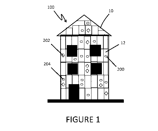
[0015] FIGURE 1 illustrates a front view of a building equipped with a
fire-
protection system according to some aspects of the present disclosure.
[0016] FIGURE 2 illustrates a side view of a system module installed
in a building
wall according to some aspects of the present disclosure.
[0017] FIGURE 3 illustrates a side view of a system module installed
in a building
wall and in an armed configuration according to some aspects of the present
disclosure.
[0018] FIGURE 4 illustrates a side view of the system module in FIGURE
3 after the
system module has moved from the armed configuration to the activated
configuration.
[0019] FIGURE 5 illustrates a side view of a system module according
to some
aspects of the present disclosure.
[0020] FIGURES 6A and 6B illustrate an example system module according
to some
aspects of the present disclosure.
[0021] FIGURES 7A and 7B illustrate an example seal-breaking element
according
to some aspects of the present disclosure.
[0022] FIGURES 8A-8D illustrate an example gas or fluid conduit
according to some
aspects of the present disclosure.
[0023] FIGURES 9A-9D illustrate an example system module according to
some
aspects of the present disclosure.
DETAILED DESCRIPTION
[0024] While the present description sets forth specific details of
various aspects of
the present disclosure, it will be appreciated that the description is
illustrative only and should
not be construed in any way as limiting. Furthermore, various applications of
such aspects and
modifications thereto, which may occur to those who are skilled in the art,
are also encompassed
by the general concepts described herein.
[0025] Generally described, the present disclosure provides systems
and modules for
temperature-dependent alarm and/or fire suppression. For the sake of
simplicity, the systems of
the present disclosure will be described in terms of a fire alarm and
prevention system for a
building structure. However, the systems and devices of the present disclosure
can be used on
other types of structures (e.g., vehicles, public structures) and for purposes
other than fire
prevention (e.g., issuing a "heat advisory" warning, monitoring for forest
fires, etc.). For
4
CA 03188509 2022-12-29
WO 2022/006321 PCT/US2021/039968
example, the systems and devices of the present disclosure can be installed on
a play structure of
a park or school. The system can monitor the ambient temperature conditions
near the play
structure. When the system detects that the ambient conditions are potentially
dangerous to
people or pets, the system can emit an alarm to inform people that the outside
conditions are
potentially dangerous for overheating. In other variants, activating the
system can trigger the
system to activate a water-misting cooling spray near the play structure. In
some aspects, the
system can include a plurality of modules that are distributed within a forest
and configured to
alert a fire-monitoring service of the coordinates of a module that has been
activated by a heat
event indicative of a fire, as described herein.
[0026] In some aspects, the present disclosure is directed to a
technology that is
designed from the ground up to fill or neutralize a limited space. For
example, a building can
have a void between an exterior cladding panel and an underlying insulation
that are attached to
the building. In some conditions, these voids can foster the spread of fire.
In some cases, the
voids can intensify the fire by providing flow paths for oxygen to feed the
fire. The systems of
the present disclosure can be arranged to neutralize these voids. In some
aspects, the systems of
the present disclosure are customizable. For example, the system can allow the
number of void-
filling units that are attached to the cladding to be adjusted to ensure the
void volume is
sufficiently filled. In some aspects, the system can be easily retrofitted
onto existing cladding and
insulation, as discussed herein.
[0027] FIGURE 1 illustrates a fire-prevention system 100, according to
some aspects
of the present disclosure. The system 100 can include one or more modules 200.
The modules
200 can be installed on a building structure 10. In the illustrated
embodiment, the modules 200
are shown installed on an exterior panel 12 of the building structure 10. In
some aspects, the
panel 12 can be a cladding structure, as described herein. In some variants,
the modules 200 can
be installed on an interior wall or surface of the building structure 10. In
some arrangements, the
modules 200 are hidden from view. For example, the illustrated modules 200 can
be hidden from
view by covering the exterior panel 12 with an overlay layer that provides a
veneer or facing to
the building structure 10. In some variants, the modules 200 are left exposed
and remain visible
after installation into the panel 12. In some variants, the modules 200 can be
sized or otherwise
arranged to blend in visually with the surrounding panel 12 so that the
appearance of the modules
200 is reduced or minimized.
CA 03188509 2022-12-29
WO 2022/006321 PCT/US2021/039968
[0028] With continued reference to FIGURE 1, the system 100 can
include different
types of modules 200. For example, the system 100 can include one or more
alarm modules 202
(denoted as open circles) and one or more fire-suppression modules 204. The
alarm module 202
can respond to a detected dangerous condition (e.g., fire) by producing an
alarm. In some
arrangements, the alarm module 202 can emit a loud noise (e.g., whistle) to
alert nearby people
that a dangerous condition (e.g., fire) has been detected. In some variants,
the alarm module 202
can be connected to a communication network and configured to alert a
monitoring service or
fire station that a dangerous condition has been detected at the building 10.
As shown in
FIGURE 1, the system 100 can include panels 12 that have different
combinations of alarm
modules 202 and fire-suppression modules 204. For example, some panels 12 can
contain one or
more alarm modules 202 and contain no fire-suppression modules 204. Some
panels 12 can
contain one or more fire-suppression modules 204 and contain no alarm modules
202. Some
panels 12 can contain a mixture of alarm modules 202 and fire-suppression
modules 204.
[0029] FIGURE 2 illustrates that in some aspects the module 200 can be
a dual-
purpose module 206 configured to perform both alarm and fire-suppression
functions. In the
illustrated embodiment, the dual-purpose module 206 is shown installed into a
panel 12 of the
building 10. In the illustrated embodiment, the dual-purpose module 206 has an
exterior portion
210 disposed at the exterior wall 20 of the building 10. In some variants, the
exterior portion 210
can be directly exposed to or in contact with the outside environment of the
building 10. In some
arrangements, the exterior portion 210 can be concealed visually beneath a
facing or covering
layer of the building 10, as described herein.
[0030] The dual-purpose module 206 can have an interior portion 212
that extends
into the building from the exterior wall 20. The panel 12 can include or
define a cladding system
in which voids or compartments 14 are formed between the exterior wall 20, an
opposing wall
22, and a plurality of spanning walls 24 that extend between the exterior wall
20 and the
opposing wall 22, as indicated in FIGURE 2. The interior portion 212 of the
dual-purpose
module 206 can extend into the compartment 14. The interior portion 212 can be
configured to
release a fire-suppressing substance 30 into the compartment 14. In some
aspects, the fire-
suppressing substance 30 can be a foam, a gel, a liquid, or a gas. The fire-
suppressing substance
30 can fill the compartment and reduce or eliminate the void within the
compartment 14. As
described herein, in some aspects the fire-suppressing substance 30 can fill
or neutralize the void
6
CA 03188509 2022-12-29
WO 2022/006321 PCT/US2021/039968
enclosed by the compartment 14. In some aspects, filling the compartment 14
with the fire-
suppressing substance 30 can slow or eliminate the spread of a fire through
the building 10. In
some aspects, the fire-suppressing substance 30 can slow or eliminate the
spread of fire over or
through the panel 12 or cladding structure of the building 10. In some
aspects, the exterior
portion 210 can be configured to emit an auditory alarm 33. In some aspects,
the dual-purpose
module 206 can be differently arranged. For example, the exterior portion 210
can be configured
to release a fire-suppressing substance 30 that is configured coat or flow
over the exterior surface
of the panel 12. In some aspects, the interior portion 212 can be configured
to emit the auditory
alarm in the compartment 14. In some aspects, the fire-suppressing substance
30 can be a gas
(e.g., carbon dioxide) and the auditory alarm can be powered by the fire-
suppressing gas as it is
released to fill the void of the compartment 14.
[0031] FIGURE 3 illustrates the module 200 can include a canister 220,
a seal-
breaking element 222, and a trigger 224. The trigger 224 can be configured to
move the module
200 from an armed configuration to an activated configuration. In the armed
configuration, the
canister 220 is sealed and full of a compressed fluid (e.g., a gas, a fire-
suppressing foam). In the
activated configuration, the canister 220 is open and the compressed fluid is
released from the
canister 220. The trigger 224 can include a temperature-sensitive material
(e.g., a shape memory
alloy). In some aspects, the trigger 224 can include a shape memory alloy
(SMA) wire 226. The
SMA wire 226 can be configured to undergo a temperature-dependent deformation
when the
module 200 reaches an elevated temperature indicative of the panel 12 being on
fire. In other
words, the SMA wire 226 can be configured to change its structure upon the
panel 12
temperature increasing beyond a temperature that would not occur under natural
environmental
conditions. The SMA wire 226 can deform to directly or indirectly cause the
release of the seal-
breaking element 222 such that the seal-breaking element 222 breaks a seal of
the canister 220,
releasing the gas or fluid contained therein. In FIGURE 3, the module 200 is
shown installed in a
panel 12 and in the armed configuration.
[0032] The module 200 can be configured to remain in the armed
configuration for a
prolong time (e.g., 30 years). In some arrangements, the module 200 can be
configured to remain
in the armed configuration for: 2 years, 5 years, 10 years, 15 years, 20
years, 30 years, 40 years,
60 years, 100 years, values between the aforementioned values, and otherwise.
In some aspects,
the modules 200 can allow the system 100 to provide fire protection for a
prolong time without
7
CA 03188509 2022-12-29
WO 2022/006321 PCT/US2021/039968
requiring any power supply to the system 100. In other words, the modules 200
can rest dormant
in the active state for years and then shift to the activated state when
needed. The modules 200
can become activated by the shape memory wire 226 being warmed to a
temperature that
indicates the module 200 is near a fire. In some aspects, the system 100 can
be retrofitted onto a
building 10 with existing panels 12. In some aspects, the system 100 can be
retrofitted onto a
building 10 by making a hole in a panel 12 of the building and installing the
module 200 into the
hole made in the panel 12. In some aspects, the system 200 can provide an
inexpensive way to
maintain fire-protection vigilance for a prolong period of time. In some
aspects, the system 100
can be installed easily. In some aspects, installation of the system 100 can
be simple and can
require only the use of a cordless drill to install modules 200 of the system
100 into existing
panels, as described herein.
[0033] FIGURE 4 illustrates a fire-suppression module 204 installed in
an exterior
wall 20. The fire-suppression module 204 is shown in the activated state in
which a fire-
suppressing substance 30 is released from the canister 220 and into the
compartment 14, as
described herein. In the illustrated embodiment, the fire-suppression module
204 includes an
SMA wire 226 that has deformed to move the seal-breaking element 222 into the
canister 220.
The SMA wire 226 can trigger the release of the fire-suppressing substance 30
by, for example,
displacing a locking pin to free a spring and drive a piercing element into a
seal. In some
arrangements, the SMA wire 226 can be embedded in a seal (e.g., rosin) that
shatters when the
SMA wire deforms.
[0034] FIGURE 5 illustrates an alarm module 202 installed in an
exterior wall 20.
The alarm module 202 is shown in the activated state in which an auditory
alarm 33 is being
emitted from the alarm module 202 as gas is released from the canister 220.
The alarm module
202 can include a horn portion 230 that generates the auditory alarm 33. In
the illustrated
embodiment, the horn portion 230 is arranged to sound outside of the
compartment 14 as the gas
within the cylinder 220 is released through the horn portion 230 to exit the
compartment 14. In
some arrangements, the horn portion 230 can be arranged to sound within the
compartment 14
and can be powered by a fire-suppressing gas (e.g., carbon dioxide) that
passes through the horn
portion 230 to enter and fill the compartment 14 with the fire-suppressing
gas. The horn portion
230 can be a sound-generating structure such as: a horn, a reed, a whistle, a
flute, a harmonica, or
other wind instrument. The alarm module 202 can include a trigger 224 that
moves the alarm
8
CA 03188509 2022-12-29
WO 2022/006321 PCT/US2021/039968
module 202 from the armed configuration to the activated configuration, as
discussed. The
trigger 224 can include an SMA wire 226, as described herein. In some aspects,
the auditory
alarm 33 can include multiple musical notes. For example, in some variants,
the auditory alarm
33 can include a first note that is generated by passing a first portion of
the escaping air from the
cylinder through a first horn, reed, key, or whistle and passing a second
portion of the escaping
gas from the cylinder through a second horn, reed, key, or whistle to generate
a second musical
note. The alarm module 202 can emit an auditory alarm 33 that includes one or
more musical
notes that are superimposed or played together. In some aspects, the alarm
module 202 can be
configured to generate a sound of: 10 dB, 20 dB, 40 dB, 60 dB, 80 dB, 120 dB,
150 dB a value
between any of the aforementioned values, and otherwise. In some aspects, the
alarm module
202 can be configured to emit an auditory alarm 33 for: 10 seconds, 30
seconds, 60 seconds, 2
minutes, 5 minutes, 10 minutes, 20 minutes, 30 minutes, 60 minutes, values
between any of the
aforementioned values, and otherwise. In some aspects, the alarm module 202 is
configured to
emit an auditory alarm 33 of 120 dB that lasts between 5 and 60 minutes.
[0035] Aspects of the present disclosure have been described in the
context of a fire-
suppression system for a building. However, the system can be used in other
conditions where
void neutralization is desired. For example, the systems disclosed herein can
be applied to a
computer case, a transformer box, a water heater, and other systems to
extinguish an interior fire.
In some aspects, the system can be arranged such that once a dangerous or
undesired heat event
occurs, the system fills the case or enclosed space with an extinguishing gas
or other substance
(e.g., fire-suppressing foam). In some arrangements, the system can be adapted
for use in interior
walls of a home or apartment. In some aspects, the system can be retrofitted
into the interior
walls of a building. The system can be tailored to fill voids formed between
the drywall and the
studs. The drywall and studs can form a cellularity or a network of voids that
are enclosed by
drywall and each pair of adjacent studs. In some aspects, the system can
attack the wall
cellularity one void at a time until the fire stops spreading.
[0036] In some aspects, the system 100 can be a network of modules 200
installed or
retrofitted into a building. For example, the system 100 can be installed or
retrofitted in an
apartment building having multiple units. Each unit can have 15 or more
modules 200 installed
to protect the unit from fire. In some aspect, the system 100 can be two
separate networks: one
network of alarms and one network of fire suppressors. In the event fire
breaks out in the
9
CA 03188509 2022-12-29
WO 2022/006321 PCT/US2021/039968
building, the alarms can act in series when the pre-set temperature is
reached. If the fire moves
throughout the building, more alarms will sound as the fire continues to grow.
In some
arrangements, fire suppressors can be set to begin going off in series,
following the path of spent
alarms. In some aspects, the fire suppressors can be set to activate at a pre-
set temperature that is
higher than the alarms. In some arrangements, the network of alarms and fire
suppressors can be
installed on the cladding of a building in sufficient number to overflow the
voids of the cladding
with a fire-suppressing gas (e.g., carbon dioxide). For example, thousands of
modules can be
installed in the exterior cladding of a building such that in the event of a
fire, the voids of the
exterior cladding are filled with a fire-suppressing gas to such an extent
that the fire is not only
slowed but is extinguished as the fire-suppressing gas flows out of the void
and down onto the
fire.
[0037] In some aspects, the system 100 can be configured to monitor a
large span of
land for wildfires. For example, with reference to FIGURE 5, the horn portion
230 of the alarm
module 202 can be replaced with a micro-generator (not shown) that is powered
by the gas that
escapes from the cylinder 220. As described herein, the alarm module 202 can
be configured
such that an SMA wire 226 deforms upon a heating of the wire 206 to a
temperature indicative of
a fire being in the vicinity of the alarm module 202, triggering the cylinder
220 to release the gas
contained within the canister 220. The gas escaping from the canister 220 can
be configured to
flow through the turbine of a micro-generator (not shown), powering the micro-
generator to
generate sufficient electricity to allow the activated alarm module 202 to
transmit a signal to a
fire-monitoring service. In some aspects, the alarm module 202 can be
configured to wirelessly
transmit the GPS coordinates of the activated alarm module 202 for five
minutes. In some
aspects, the system 100 can include a plurality of alarm modules 202 that are
distributed across a
large span of land that is susceptible to fire (e.g., forest). The plurality
of alarm modules 202 can
be suspended from trees (e.g., dropped from aircraft) or installed into trees
by driving the module
202 into the trunk of the tree. The plurality of alarm modules 202 can provide
an economical,
fire-monitoring network or system 100 for monitoring the span of land over
which the plurality
of modules 202 is distributed. In some aspects, one or more gas-powered micro-
generator alarm
modules 202 can be included in the fire-suppression systems 100 described
herein with regard to
buildings. The alarm modules 202 can be configured to transmit to a fire-
monitoring service or to
CA 03188509 2022-12-29
WO 2022/006321 PCT/US2021/039968
a nearby fire-station the GPS coordinates of an alarm module 202 that has been
activated by a
heat event indicative of a fire in the vicinity of the alarm module 202.
[0038] FIGURES 6A and 6B illustrate an example implementation of a
dual purpose
module 206 in accordance with the present technology. The dual purpose module
206 includes a
cylinder 220 and a trigger 224 that moves the dual purpose module 206 from the
armed
configuration to the activated configuration, as discussed elsewhere herein.
The dual purpose
module 206 further includes a horn portion 230, including a bell 231, that
generates an auditory
alarm.
[0039] The cylinder 220 may be screwed into the trigger 224 and is
further retained
relative to the trigger 224 by one or more SMA wires 226. In the example
implementation of
FIGURES 6A and 6B, the one or more SMA wires 226 are in the form of a single
loop of SMA
wire 226 looped around retaining knobs 228 of the trigger 224 and passing
through a retaining
structure 227 at an opposite end of the cylinder 220. The loop of SMA wire 226
is configured to
deform by contracting (e.g., by up to 2%, 3%, 4%, 5%, or more, of the length
of the SMA wire
226). As the SMA wire 226 contracts at a high temperature as disclosed
elsewhere herein, the
length of the loop of SMA wire 226 decreases such that the cylinder 220 is
drawn closer to the
trigger 224. As the cylinder 220 is drawn toward the trigger 224, a sealed tip
of the cylinder
contacts a seal-breaking element 232 (FIGURES 7A-7B) disposed at least
partially within the
trigger 224, puncturing the seal and allowing pressurized gas or fluid to
leave the cylinder 220.
The pressurized gas or fluid leaving the cylinder activates the horn portion
230 to create an
audible alarm, and at least partially fills a void around the dual purpose
module 206, as described
elsewhere herein.
[0040] FIGURES 7A and 7B illustrate an example seal-breaking element
232
according to some aspects of the present disclosure. In some embodiments, the
seal-breaking
element 232 may be implemented within the trigger 224 and/or horn portion 230
of any of the
modules disclosed herein, such as the dual purpose module 206 of FIGURES 6A-
6B. The seal-
breaking element 232 includes a needle 234 and a gas or fluid conduit 238.
[0041] The needle 234 is a hollow tubular structure having an angled
tip 236 adapted
to puncture the seal of a cylinder such as cylinder 220 (FIGURES 6A-6B). The
needle 234 may
include any material, such as a metal or a polymeric material, suitably rigid
to retain dimensional
stability and puncture the seal of the cylinder 220 when the cylinder 220
contacts the tip 236.
11
CA 03188509 2022-12-29
WO 2022/006321 PCT/US2021/039968
Upon puncturing the seal, gas or fluid leaving the cylinder 220 travels
through at least a portion
of the needle 234 and through the gas or fluid conduit 238.
[0042] FIGURES 8A-8D illustrate the example gas or fluid conduit 238
of FIGURES
7A-7B. FIGURE 8A is a side view of the conduit 238; FIGURE 8C is an additional
side view of
the conduit 238 taken at an angle perpendicular to the view of FIGURE 8A, as
indicated by
arrow 8C in FIGURE 8A. FIGURE 8B is a partial enlarged view of distal section
240 indicated
by arrow 8B in FIGURE 8A. FIGURE 8D is a partial enlarged view of distal
section 240
indicated by arrow 8D in FIGURE 8C.
[0043] The conduit 238 is a hollow tubular structure including a
distal section 240
configured to receive gas and/or fluid from a cylinder 220 (FIGURES 6A-6B).
The distal
section 240 includes at least one opening through which the gas and/or fluid
can enter the
conduit 238. In the example conduit 238 of FIGURES 8A-8D, the distal section
240 includes
side slots 242 disposed on opposing sides of the conduit 238. An end slot 244
is disposed at the
end of the distal section 240. Thus, when the tip 236 of needle 234 (FIGURES
7A-7B)
punctures the seal of a cylinder, the pressured gas and/or fluid leaving the
cylinder can enter the
conduit 238 through the side slots 242 and the end slot 244.
[0044] The size, shape, and configuration of side slots 242 and/or end
slot 244 can
advantageously control the pressure of gas and/or fluid entering the horn
portion 230 (FIGURES
6A-6B) of a module. For example, in some embodiments the module may use a
cylinder
containing gas or fluid at a pressure substantially higher than a pressure
desired for operation of a
horn portion of a module. In some embodiments, the configuration illustrated
in FIGURES 8A-
8D may be suitable to reduce the pressure of gas or fluid entering the horn
portion. For example,
the configuration of side slots 242 and end slot 244 of the conduit 238 may be
suitable for
reducing a high pressure gas or fluid (e.g., up to 100 psi, 200 psi, 300 psi,
400 psi, 500 psi, 600
psi, 700 psi, 800 psi, 900 psi, 1000 psi, or more within the cylinder) to a
lower pressure upon
leaving the conduit 238 at a proximal end opposite the distal section 240
(e.g., as low as 100 psi,
90 psi, 80 psi, 70 psi, 60 psi, 50 psi, 40 psi, 30 psi, 20 psi, or lower).
[0045] FIGURES 9A-9D illustrate an example alarm module 202 according
to some
aspects of the present disclosure. In various embodiments, an alarm module 202
as illustrated in
FIGURE 1 may be powered by compressed gas or fluid, and/or by electricity. The
example
alarm module 202 of FIGURES 9A-9D is configured to emit an auditory alarm
and/or a visible
12
CA 03188509 2022-12-29
WO 2022/006321 PCT/US2021/039968
alarm using electrical power. FIGURE 9A is a front perspective view of the
alarm module 202.
FIGURES 9B and 9C are rear perspective views of the alarm module 202. FIGURE
9D is a
partial enlarged side perspective view of the alarm module 202 illustrating a
triggering
mechanism of the alarm module 202.
[0046] The alarm module 202 includes a housing 250 containing a source
of
electrical power such as one or more batteries 252. The housing 250 can
further include one or
more light sources 256, such as light-emitting diodes (LED), strobes (e.g.,
LED strobes), or other
light sources configured to emit light, disposed on or at least partially
within the housing 250. A
sound emitter 258, such as a speaker, electromagnetic horn, or the like, can
also be disposed on
or at least partially within the housing 250, such as on a rear surface 251 of
the housing 250.
[0047] The batteries 252 can be disposed within a battery holder 254
having circuitry
therein for connecting the terminals of the batteries 252 to power the one or
more light sources
256 and/or the sound emitter 258. In an armed configuration, as shown in
FIGURES 9A-9D, an
insulator 260 is disposed between at least one terminal 262 of batteries 252
and a corresponding
contact of the battery holder 254 such that electricity does not flow through
the battery circuit to
power the one or more light sources 256 and/or the sound emitter 258.
[0048] To trigger the alarm module 202 at a high temperature
associated with a fire
being in the vicinity of the alarm module 202, a SMA wire 262 is disposed on
or within the
housing 250, such as along the rear surface 251 of the housing 250. The SMA
wire 264 has a
first end 266 anchored to the housing 250 and a second end 268 connected to
the insulator 260
by a flexible connector 270, such as a flexible metallic or polymeric ribbon,
or the like. When
the SMA wire 264 reaches a temperature high enough to cause deformation, the
SMA wire
contracts or shortens, pulling on the flexible connector 270. The flexible
connector 270 in turn
pulls the insulator 260 outward such that the insulator 260 is removed from
its location between
the terminal 262 and the corresponding contact, completing the battery
circuit.
[0049] Upon removal of the insulator 260 from the battery holder 254,
electricity
from the batteries 252 activates the one or more light sources 256 and/or the
sound emitter 258.
In some embodiments, the one or more light sources 256 are configured, when
activated by
electricity, to act as a strobe light by emitting light in a repeating pattern
of flashes consistent
with a fire alarm strobe. In some embodiments, the sound emitter 258 is
configured, when
activated by electricity, to emit an alarm sound such as a horn (e.g., an
electromagnetic horn), a
13
CA 03188509 2022-12-29
WO 2022/006321 PCT/US2021/039968
buzzer, one or more musical notes, or any other alarm sound at any suitable
volume as described
elsewhere herein. In some embodiments, the sound emitter 258 is configured to
play a verbal
warning message (e.g., "FIRE!", etc.). In some embodiments, the sound emitted
by the sound
emitter 258 is selected to interact with a voice-activated device such as a
network-connected
device (e.g., a digital assistant, a smart speaker, etc.). For example, the
sound emitter 258 may
play a message such as "Okay Google, call 911" or any other message suitable
for activating a
voice-activated device and causing the device to contact emergency services.
In some
embodiments, the sound emitter 258 may be configured to sequentially play a
number of
different messages selected to activate different types of voice-activated
devices so as to increase
the probability that a voice-activated device nearby will be activated upon
triggering of the alarm
module 202.
[0050] While certain arrangements of the present disclosure have been
described
above, it should be understood that they have been presented by way of example
only, and not of
limitation. It will be apparent to persons skilled in the relevant art that
various changes in form
and detail can be made therein without departing from the spirit and scope of
the inventions.
Thus the present inventions should not be limited by the above-described
exemplary
embodiments, but should be defined only in accordance with the following
claims and their
equivalents. Furthermore, while certain advantages of the inventions have been
described herein,
it is to be understood that not necessarily all such advantages may be
achieved in accordance
with any particular embodiment of the inventions. Thus, for example, those
skilled in the art will
recognize that the inventions may be embodied or carried out in a manner that
achieves or
optimizes one advantage or group of advantages as taught herein without
necessarily achieving
other advantages as may be taught or suggested herein.
14