Note: Descriptions are shown in the official language in which they were submitted.
CA 03188641 2022-12-29
WO 2022/006599 PCT/US2021/070818
100011 TITLE OF THE INVENTION
[0002] Emissions Reduction Systems and Methods.
[0003] CROSS REFERENCE TO RELATED APPLICATIONS
[0004] Not applicable.
[0005] STATEMENT REGARDING FEDERALLY SPONSORED
RESEARCH OR DEVELOPMENT
[0006] Not applicable.
[0007] REFERENCE TO APPENDIX
[0008] Not applicable.
[0009] BACKGROUND OF THE INVENTION
[00:10] Field of the Invention. The present inventions relate
generally to
catalytic reaction chambers for combustion exhaust gases commonly referred to
as catalytic converters.
[0011] Description of the Related Art.
[0012] United States Patent No. 7,807,120 entitled High-Efficiency
Catalytic Converters For Treating Exhaust Gases discloses "[s]everal
embodiments of high-efficiency catalytic converters and associated systems and
methods H. in one embodiment, a catalytic converter for treating a flow of
exhaust gas comprising a reaction chamber, a heating enclosure enclosing at
least a portion of the reaction chamber, and an optional coolant channel
encasing
the heating enclosure. The reaction chamber can have a first end section
through
which the exhaust gas flows into the reaction chamber and a second end section
from which the exhaust gas exits the reaction chamber. The heating enclosure
is configured to contain heated gas along the exterior of the reaction
chamber,
and the optional coolant channel is configured to contain a flow of coolant
around the heating enclosure. The catalytic converter can further include a
catalytic element in the reaction chamber."
CA 03188641 2022-12-29
WO 2022/006599 PCT/US2021/070818
[0013] United States Patent Application Publication No.
2020/0018207
entitled Exhaust Gas System discloses "[a]n exhaust system for the
aftertreatment of exhaust gases of an internal combustion engine, having an
annular catalytic converter which is flowed through by exhaust gas, wherein
the
annular catalytic converter has an inflow point and an outflow point and the
annular catalytic converter has a tubular first flow path and an annular
second
flow path which are oriented concentrically with respect to one another and
which are flowed through in series, wherein the first flow path is surrounded
to
the outside in a radial direction by the second flow path, wherein a pipe is
led in
io the radial direction from the outside through the second flow path,
wherein the
pipe opens into the annular catalytic converter and the pipe has a radial
extent
at least as far as into the inner first flow path."
[0014] United States Patent No. 3,768,982 entitled Catalytic
Converter
with Electrically Preheated Catalyst discloses "[Neat from an electric heater
is
transferred conductively through a monolithic support to a catalyst located on
the surfaces of the monolithic support. Engine exhaust gases passing through
the monolithic support contact the heated catalyst, which assists in
converting
undesirable components of the exhaust gases into less harmful components.
Supplemental air is supplied to the exhaust gases from an annular distributing
space located at the converter inlet."
[0015] The inventions disclosed herein are directed to improved
high
efficiency catalyst-based emission reduction systems and methods of use.
[0016] BRIEF SUMMARY OF THE INVENTIONS
[0017] While not all aspects of my inventions disclosed herein will
be
summarized, a brief summary of one aspect of my inventions includes an
internal combustion engine emission reduction system comprising a first
catalyst element configured for oxidizing catalytic reactions, a second
catalyst
element configured for reduction catalytic reactions, and configured to direct
a
2
CA 03188641 2022-12-29
WO 2022/006599 PCT/US2021/070818
portion of exhaust that has been reacted by the first or first and second
catalyst
elements back through the first catalyst element.
[0018] A brief summary of other aspects of my inventions includes
an
internal combustion engine emission reduction system comprising a first
catalyst element configured for reducing catalytic reactions, a second
catalyst
element configured for oxidizing or redox catalytic reactions, and configured
to
direct a portion of exhaust that has been reacted by the first or first and
second
catalyst elements back through the first catalyst element.
[0019] A brief summary of other aspects of my inventions includes
an
io internal combustion engine emission reduction system comprising a body
having a primary emission inlet and an emission outlet; a first catalyst
element
having a first catalytic function and disposed within the body between the
emission inlet and the emission outlet such that all of the emissions flowing
into
the inlet flow through the first catalyst element; a second catalyst element
disposed within the body and disposed to surround an outer surface of the
first
catalyst element, and having a second catalytic function that is different
from
the first catalytic function; a wall disposed between an outer surface of the
first
catalyst element and an inner surface of the second catalyst element, and
configured to transfer heat from the first catalyst element to the second
catalyst
element and configured to prevent emissions flowing in the first catalyst
element
from leaking into the second catalyst element; a diverter disposed within the
body between the emission outlet and a downstream end of the first catalyst
element, and configured to divert less than all of the emissions flowing out
of
the first catalyst element to flow in a countercurrent direction through the
second
catalyst element; and a secondary emissions inlet disposed within the body and
associated with the primary emission inlet and an upstream end of the first
catalyst element, and configured to allow emissions flowing through the second
catalyst element to flow into the first catalyst element with emissions from
the
3
CA 03188641 2022-12-29
WO 2022/006599 PCT/US2021/070818
primary emissions inlet. The secondary emissions inlet may comprise a
plurality of openings shrouded with respect to emissions flowing in the
primary
emission inlet. The plurality of shrouded openings may be formed in the
primary emissions inlet. The plurality of shrouded openings may be formed in
an inlet transition disposed between the primary emissions inlet and the first
catalyst element. The plurality of shrouded openings may be formed at a
common radial distance from an inlet centerline. The plurality of shrouded
openings may be formed at a plurality of radial distances from an inlet
centerline. The secondary emissions inlet may comprise at least one channel
io formed in an inlet transition and located within the body such that the
at least
one channel is shrouded by an end of the primary emission inlet with respect
to
emissions flowing through the primary emission inlet. The secondary emissions
inlet may comprise a plurality of channels formed at a common radial distance
from an inlet centerline. The secondary emissions inlet may comprise a
plurality
of channels formed at a plurality of radial distances from an inlet
centerline. The
first catalyst element may be configured for oxidation reactions, and the
second
catalyst element may be configured for reduction reactions. The first catalyst
element may be configured for reduction reactions, and the second catalyst
element may be configured for oxidation reactions.
[0020] A brief summary of other aspects of my inventions includes a
method of reducing undesirable emissions from internal combustion engine
exhaust comprising flowing engine exhaust through a first catalyst element to
cause a desired first chemical reaction in the engine exhaust; diverting at
least a
portion of the engine exhaust that has passed through the first catalyst
element;
flowing the diverted portion of engine exhaust through a second catalyst
element
to cause a desired second chemical reaction in the diverted engine exhaust;
and
mixing the diverted engine exhaust that has passed through the second catalyst
element with engine exhaust entering the first catalyst element. Diverting at
4
CA 03188641 2022-12-29
WO 2022/006599 PCT/US2021/070818
least a portion of the engine exhaust may comprise diverting between about 10%
and about 30% of the engine exhaust that has passed through the first catalyst
element.
[0021] A brief summary of other aspects of my inventions includes
an
emission reduction system for an internal combustion engine comprising a body
having a primary emission inlet and an emission outlet; a first catalyst
element
having a first catalytic function and disposed within the body between the
emission inlet and the emission outlet such that at least a portion of the
emissions
flowing into the emission inlet flow through the first catalyst element; a
second
io catalyst element disposed within the body and surrounding an outer
surface of
the first catalyst element, and having a second catalytic function that is
different
from the first catalytic function; a recycle flow path disposed within the
body
and configured to divert all of the emissions flowing out of the second
substrate
into a recycle flow path; and a secondary emissions inlet disposed within the
body and associated with the primary emission inlet and an end of the first
catalyst element, and configured to permit emissions flowing in the recycle
pathway to mix with emissions exiting the primary emissions inlet. The
secondary emissions inlet may comprise a plurality of openings shrouded with
respect to emissions flowing in the primary emission inlet. The plurality of
shrouded openings may be formed in the primary emissions inlet. The plurality
of shrouded openings may be formed in an inlet transition disposed between the
primary emissions inlet and the first catalyst element. The plurality of
shrouded
openings may be formed at a common radial distance from an inlet centerline.
The plurality of shrouded openings may be formed at a plurality of radial
distances from an inlet centerline. The secondary emissions inlet comprises at
least one channel formed in an inlet transition and located with the body such
that the at least one channel is shrouded by an end of the primary emission
inlet
with respect to emissions flowing through the primary emission inlet. The
inlet
5
CA 03188641 2022-12-29
WO 2022/006599 PCT/US2021/070818
transition may comprise a plurality of channels formed at a common radial
distance from an inlet centerline. The inlet transition may a plurality of
channels
formed at a plurality of radial distances from an inlet centerline. The first
catalyst element may be configured for oxidation reactions, and the second
catalyst element is configured for reduction reactions. The first catalyst
element
may be configured for reduction reactions, and the second catalyst element may
be configured for oxidation reactions.
[0022] A brief summary of other aspects of my inventions includes a
method of reducing undesirable components in internal combustion engine
io exhaust comprising flowing a first portion of engine exhaust through a
first
catalyst element to cause a desired first chemical reaction in the first
portion of
the engine exhaust; flowing a second portion of engine exhaust through a
secondary catalyst reaction chamber to cause a desired second chemical
reaction
in the second portion of engine exhaust; redirecting the second portion of
engine
exhaust that has passed through the secondary catalyst element to an inlet for
the first catalyst element; and mixing the redirected second portion of engine
exhaust with engine exhaust entering the first catalyst element. Redirecting
the
second portion of the engine exhaust may comprise redirecting between about
10% and about 30% of the engine exhaust that has passes through the first and
second catalyst elements.
[0023] BRIEF DESCRIPTION OF THE SEVERAL VIEWS OF THE
DRAWINGS
[0024] The following figures form part of the present specification
and are
included to demonstrate further certain aspects of the present invention. The
invention may be better understood by reference to one or more of these
figures
in combination with the detailed description of specific embodiments presented
herein.
6
CA 03188641 2022-12-29
WO 2022/006599 PCT/US2021/070818
[0025] FIG. lA illustrates an embodiment of a catalytic reaction
chamber
according to aspects of the inventions disclosed herein.
[0026] FIG. 1B illustrates another embodiment of a catalytic
reaction
chamber according to aspects of the inventions disclosed herein.
[0027] FIG. 2 illustrates another embodiment of a catalytic reaction
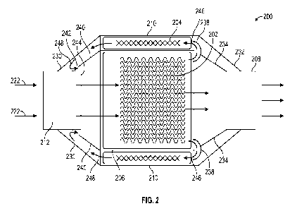
chamber according to aspects of the inventions disclosed herein.
[0028] FIG. 3 illustrates an embodiment of flow mixer useful with
catalytic reaction chambers according to aspects of the inventions disclosed
herein.
io [0029] FIGs. 4A and 4B illustrate inlet components useful with
catalytic
reaction chambers according to aspects of the inventions disclosed herein.
[0030] FIG. 5 illustrates another inlet component useful with
catalytic
reaction chambers according to aspects of the inventions disclosed herein.
[0031] FIG. 6 illustrates an outlet component useful with catalytic
reaction
chambers according to aspects of the inventions disclosed herein.
[0032] FIGs. 7A and 7B illustrates catalytic reaction chambers with
embedded heating elements.
[0033] FIG. 8 illustrates a catalytic reaction chamber having a
fluid flow
path on the outer periphery of the chamber.
[0034] While the inventions disclosed herein are susceptible to various
modifications and alternative forms, only a few specific embodiments have been
shown by way of example in the drawings and are described in detail below.
The figures and detailed descriptions of these specific embodiments are not
intended to limit the breadth or scope of the inventive concepts or the
appended
claims in any manner. Rather, the figures and detailed written descriptions
are
provided to illustrate the inventive concepts to a person of ordinary skill in
the
art and to enable such person to make and use the inventive concepts.
[0035] DETAILED DESCRIPTION
7
CA 03188641 2022-12-29
WO 2022/006599 PCT/US2021/070818
[0036] The Figures attached hereto and described above, and the
written
description of the figures, specific structures and functions below are not
presented to limit the scope of what I have invented or the scope of the
appended
claims. Rather, the figures and written description are provided to teach any
person skilled in the art to make and use the inventions for which patent
protection is sought. Those skilled in the art will appreciate that not all
features
of a commercial embodiment of the inventions are described or shown for the
sake of clarity and understanding. Persons of skill in this art will also
appreciate
that the development of an actual commercial embodiment incorporating
aspects of the present inventions will require numerous implementation-
specific
decisions to achieve the developer's goal for the commercial embodiment. Such
implementation-specific decisions may include, and likely are not limited to,
compliance with system-related, business-related, government-related, and
other constraints, which may vary by specific implementation, location and
from
time to time. While a developer's efforts might be complex and time-consuming
in an absolute sense, such efforts would be, nevertheless, a routine
undertaking
for those of skill in this art having benefit of this disclosure. It must be
understood that the inventions disclosed and taught herein are susceptible to
numerous and various modifications and alternative forms. For example, the
use of a singular term, such as, but not limited to, "a," is not intended as
limiting
of the number of items. Also, the use of relational terms, such as, but not
limited
to, "top," "bottom," "left," "right," "upper," "lower," "down," "up," "side,"
and
the like are used in the written description for clarity in specific reference
to the
figures and are not intended to limit the scope of the invention or the
appended
claims.
[0037] Aspects of the inventions disclosed herein may be embodied
as an
apparatus, system, or method. Accordingly, specific embodiments may take the
form of an entirely hardware embodiment, or an embodiment combining
8
CA 03188641 2022-12-29
WO 2022/006599 PCT/US2021/070818
software and hardware aspects, such as a "circuit," "module" or "system."
Furthermore, embodiments of the present inventions may take the form of a
computer program product embodied in one or more computer readable storage
media having computer readable program code.
[0038] Reference throughout this disclosure to "one embodiment," "an
embodiment," or similar language means that a particular feature, structure,
or
characteristic described in connection with the embodiment is included in at
least one of the many possible embodiments of the present inventions. The
terms "including," "comprising," "having," and variations thereof mean
"including but not limited to" unless expressly specified otherwise. An
enumerated listing of items does not imply that any or all of the items are
mutually exclusive and/or mutually inclusive, unless expressly specified
otherwise. The terms "a," "an," and "the" also refer to "one or more" unless
expressly specified otherwise.
[0039] Furthermore, the described features, structures, or characteristics
of one embodiment may be combined in any suitable manner in one or more
other embodiments. Those of skill in the art having the benefit of this
disclosure
will understand that the inventions may be practiced without one or more of
the
specific details, or with other methods, components, materials, and so forth.
In
other instances, well-known structures, materials, or operations are not shown
or described in detail to avoid obscuring aspects of the disclosure.
[0040] The description of elements in each figure may refer to
elements of
proceeding figures. Like numbers refer to like elements in all figures,
including
alternate embodiments of like elements. In some possible embodiments, the
functions/actions/structures noted in the figures may occur out of the order
noted
in the block diagrams and/or operational illustrations. For example, two
operations shown as occurring in succession, in fact, may be executed
9
CA 03188641 2022-12-29
WO 2022/006599 PCT/US2021/070818
substantially concurrently or the operations may be executed in the reverse
order, depending upon the functionality/acts/structure involved.
[0041] In general terms, I have invented catalytic reaction
chambers useful
in reducing unwanted combustion gas products, such as carbon monoxide and
nitrogen oxides, volatile organic hydrocarbons (VHOC) and/or particulates
from internal combustion engine exhaust. Catalytic reaction chambers also may
be referred to in the art as catalytic converters, two-way oxidizing
converters,
three-way redox converters, four-way oxygen injection converters, and/or
diesel
oxidation converters. Although these reaction chambers are primarily used in
io exhaust systems for automobiles, they also are used on trucks, buses,
forklifts,
mining equipment, generator sets, locomotives, motorcycles, airplanes and
other
vehicles and equipment having internal combustion engines, and on some wood
stoves. Reaction chambers incorporating my inventions may comprise first and
second catalytic beds, matrices, or monoliths.
[0042] For purposes of this disclosure I will use the general term
"catalyst
element" to refer to a flow-through substrate, such as a core, bed, matrix, or
monolith to which catalytic activity has been added. As is known, the flow
through substrate may be a ceramic monolith or a ceramic honeycomb structure.
The substrate also may be formed from a metallic foil, which is typically made
from iron, chromium, aluminum, stainless steel, or combinations thereof.
Regardless of the type or form of substrate, substrates are designed to
provide a
flow through structure with large surface area to which the catalytic activity
may
be applied. The catalytic activity may be applied to the substrate as a
washcoat,
which is basically a water-based carrier for the catalytic material that is
then
dried and calcined. The washcoat may comprise oxides, such as titanium
dioxide, aluminum oxide, silicon dioxide or combinations of oxides, to provide
a rough, irregular surface to increase the surface area for the catalytic
material.
The catalytic material may be present in the washcoat or may be separately
CA 03188641 2022-12-29
WO 2022/006599 PCT/US2021/070818
impregnated in or applied to the washcoat. During calcination, the catalyst
materials decompose to the final material, usually a metal or a metal oxide,
having the catalytic activity.
[0043] A first or primary catalyst element may comprise oxidation,
reduction, or reduction/oxidation (redox) catalyst material or materials,
including one or more of platinum, palladium, rhodium, cerium, iron,
manganese, nickel or copper configured to oxidize carbon monoxide to carbon
dioxide, oxidize unbumt hydrocarbons to carbon dioxide and water, and/or
reduce nitrogen oxides to nitrogen. The second catalyst element also may
comprise oxidation, reduction, or reduction/oxidation (redox) catalyst
material
or materials, including one or more of platinum, palladium, rhodium, cerium,
iron, manganese, nickel or copper configured to oxidize carbon monoxide to
carbon dioxide, oxidize unbumt hydrocarbons to carbon dioxide and water,
and/or reduce nitrogen oxides to nitrogen. Preferably, the second catalyst
element comprises a reduction catalyst material, such as cerium or rhodium, or
a NO, adsorber, such as zeolite, to reduce nitrogen oxides to nitrogen, or
capture
nitrogen oxides. By physically separating the second catalyst element from the
first catalyst element, the effectiveness of each catalyst element may be
maximized and/or parasitic effects of the catalyst materials may be mitigated.
For example, it is known that cerium may reduce the effectiveness of a
platinum-
bearing catalyst element. Additionally, the catalytic activity of the second
catalyst element may be selected to eliminate the need for urea injection in
diesel
applications. It is presently preferred, but not required, that the first
catalyst
element be configured as a three-way redox catalyst, and the second catalyst
be
configured as a reduction catalyst. Alternately, the first catalyst element
may
be configured as a reduction catalyst, and the second catalyst element
configured
as a redox catalyst.
11
CA 03188641 2022-12-29
WO 2022/006599 PCT/US2021/070818
[0044] In some embodiments, the primary catalyst element is housed
within a metal casing or body and the secondary catalyst element may form an
annular ring around the primary catalyst element on the outside of the metal
casing. Uncatalyzed or unreacted combustion gases (i.e., combustion gases
upstream of the catalyst elements) flow effectively simultaneously through
both
the primary and secondary catalyst elements. Reacted exhaust gases (i.e.,
combustions gases that have passed through a catalyst element) exiting the
secondary catalyst element are diverted or directed back to the reaction
chamber
inlet and injected, entrained, or mixed with incoming unreacted combustion
gases. The amount of diverted or redirected reacted gases may range between
about 2% to about 45%, by volume, and preferably between about 10% and
about 30% of the total volume of exhaust gases flowing through the reaction
chamber.
[0045] In other embodiments, the primary catalyst element may be
housed
within a metal casing or body and the secondary catalyst element may form an
annular ring around the outside of the metal casing. The reaction chambers are
configured such that unreacted combustion gases flow first through the primary
catalyst element. A portion of the exhaust gases reacted by the primary
catalyst
element are diverted or redirected, after exiting the primary catalyst
element, to
pass through the secondary catalyst element and then to the primary catalyst
element reaction chamber inlet and. Gases reacted by the secondary catalyst
are
then injected, entrained, or mixed with incoming unreacted combustion gases.
The amount of diverted or redirected reacted gases may range between about
2% to about 45%, by volume, and preferably between about 10% and about
30%.
[0046] While it is contemplated that many embodiments will utilize
cylindrical or substantially cylindrical first catalyst elements, and second
catalyst elements comprising an elongated toroid, it will be appreciated that
12
CA 03188641 2022-12-29
WO 2022/006599 PCT/US2021/070818
catalyst shapes other than cylinders and elongated toroids may be used. For
example, but not limitation, the first catalyst element may have an oval or
elliptical cross-section (e.g., an elliptical cylinder), and the second
catalyst
element may have a corresponding elongated toroidal shape.
[0047] In other embodiments, a flow mixer may be placed in the reaction
chamber inlet to mix the recycled reacted gases from the secondary catalyst
element more effectively with the unreacted combustion gases.
[0048] In other embodiments, a heating element, including but not
limited
to a tungsten heating element, may be placed within the primary catalyst
element
io and may be configured to raise the temperature of the primary catalyst
element
to optimum operation temperature, for example, to temperatures of between
about 700 F to about 900 F or higher. The heating element may be powered by
AC or DC power generated by the internal combustion engine or stored in a
battery. The metal casing between the primary and secondary catalyst may be
configured to transfer heat from the primary catalyst to secondary catalyst.
For
those applications, such as diesel engines, where the combustion temperature
(i.e., the temperature of the engine exhaust in the catalyst elements) is
insufficient to create a "clean" burn with low particulate matter, the heating
element may be activated to reduce emissions. For example, a catalytic
reaction
chamber utilizing aspects of the inventions disclosed herein may eliminate the
need for diesel particulate filters.
[0049] In other embodiments, the reaction chamber is surrounded by
one
or more fluid conduits or channels that is configured to transfer heat from
the
reaction chamber to one or more fluids flowing through the conduits or
channels.
For example, aircraft flying at high altitudes or vehicles and equipment
operating in cold climates may benefit from preheating fuel in the fluid
conduit
associated with the reaction chamber. In addition, passenger compartment heat
may be supplied by a heater fluid circulated through the fluid conduit. It
will be
13
CA 03188641 2022-12-29
WO 2022/006599 PCT/US2021/070818
appreciated that other fluids associated with vehicles or equipment having
internal combustion engines may utilize the fluid conduit associated with the
reaction chamber to heat, including preheat, one or more of the fluids.
[0050] Turning now to more detailed descriptions of several
embodiments,
FIG. lA illustrates a reaction chamber 100 comprising a first catalyst element
102 and a second catalyst element 104. In this embodiment, the first catalyst
element 102 may be housed in a first housing 106, which may also comprise the
reaction chamber outlet 108. It is preferred that the first housing 106 or
first
housing/outlet combination comprise a metal alloy material, such as alloy
steel,
stainless steel, aluminum, titanium, or the like, suitable to withstand the
operating conditions and to facilitate heat transfer out of the first catalyst
element 102 and yet prevent combustion gas from leaking out of the first
catalyst
element 102. In some embodiments, the first housing 106 / outlet 108 may
comprise a cylindrical length of metal pipe into which the first catalyst
element
102 may be securely deployed, as illustrated in FIG. 1A.
[0051] The second catalyst element 104 preferably is cylindrically
shaped
and disposed about the outer surface of the first housing 106 as illustrated.
A
second housing 110 is disposed about the outer surface of the second catalyst
element 104 and is configured to allow combustion gas 122 to flow through the
second catalyst element 104 without leaking into the first catalyst element
102.
It is preferred that the second housing 110 comprise a metal alloy material,
such
as alloy steel, stainless steel, aluminum, titanium, or the like. In most
embodiments the second housing 110 will be made from the same material as
the first housing 106. The second housing 110 also may comprise a cylindrical
length of metal pipe into which the second catalyst element 104 may be
securely
deployed as illustrated in FIG. 1A.
[0052] The reaction chamber 100 illustrated in FIG. lA also
comprises an
inlet 112 configured to communicate combustion gases to the first and second
14
CA 03188641 2022-12-29
WO 2022/006599 PCT/US2021/070818
catalyst elements 102, 104. In FIG. 1A, the diameter of the catalyst elements
102, 104 is larger than the diameter of the inlet 112. In this circumstance,
the
reaction chamber 100 may comprise an inlet transition 114 that joins, such as
by
welding, fastening, crimping or other joining methods, the outer housing 110
to
the inlet 112 so that the combustion gas entering the reaction chamber 100
flow
through the first and second catalyst elements 102, 104. In those
circumstances
where the diameter of the catalyst elements matches the diameter of the inlet,
an
inlet transition may not be needed.
[0053] An outer shell 116 forms the outer surface of the reaction
chamber
io 100 and defines a plenum 118 through which gases reacted by the second
catalyst element 104 may flow. As illustrated in FIG. 1A, the outer shell 116
is
joined or sealed to the outlet 108 and to the inlet 112. It is preferred that
the
outer shell 116 comprise a metal alloy material, such as alloy steel,
stainless
steel, aluminum, titanium, or the like. In some embodiments the outer shell
will
be made from the same material as the first housing 106 and second housing
110. In other embodiments, the outer shell may be formed from a dissimilar
material.
[0054] The embodiment illustrated in FIG. lA further comprises one
or
more secondary inlets 120 configured to allow the plenum 118 to fluidly
communicate with the inlet 112 region through which unreacted combustion gas
122 may flow. It is preferred that the secondary inlet(s) 120 be shielded or
shrouded with respect to the upstream flow of combustion gases to aid or
benefit
the flow of reacted combustion gases 124 back into the inlet 112 region. For
example, secondary inlet(s) 120 may be formed in the inlet 112 by mechanically
punching or drawing an opening 126. The material that is drawn or punched
may form a shield 128 shrouding all or part of the opening 126 from the
upstream flow 122 as illustrated in FIG. 1A. Combustion gases 122 flowing
over and past the shielded secondary inlet(s) 120 preferably create a region
of
CA 03188641 2022-12-29
WO 2022/006599 PCT/US2021/070818
lower pressure at the opening(s) 126 to facilitate the flow reacted combustion
gases 124 into the inlet 112 region.
[0055] As will now be appreciated for the embodiment of FIG. 1A,
the
reaction chamber 100 may be placed in an exhaust system (not shown) so that
combustion gases 122 flow into inlet 112 and then through the first and second
catalyst elements 102, 104. The portion of combustion gases 122 that flow
through and react with the first catalyst element 102 exit the reaction
chamber
100 through outlet 108. The portion of combustion gases 122 that flow through
and react with the second catalyst element 104 are directed into the plenum
118
io and flow in a direction opposite to the combustion gases 122 and back to
the
inlet 112 region. These reacted gases 124 are drawn or forced into the inlet
112
region and mix with incoming unreacted combustion gases 122. This combined
mixture of unreacted combustion gases 122 and reacted gases 124 flows again
through both the first and second catalyst elements 102, 104.
[0056] In the embodiment of FIG. 1A, the volumetric split of combustion
gases between the first and second catalyst elements 102, 104 is determined
mostly, if not exclusively, by the inlet area (e.g., cross-sectional area) of
the
catalyst elements. For example, if the first catalyst element 102 is
effectively
cylindrical in shape and has a diameter of 3 inches, and if the second
catalyst
element 104 also is effectively a hollow cylinder (elongated toroid) in shape
with an annular thickness of 1/4 inch, about 70% of the combustion gases will
flow through the first catalyst element and the remaining about 30% will flow
through the second catalyst 104. In other words, such an embodiment would
have a recycle factor of about 0.3. It is preferred that the recycle factor
range
between about 0.02 and about 0.45, and most preferably between about 0.10 and
0.30.
[0057] In FIG. 1A, the first catalyst element 102 may comprise an
oxidation or a reduction/oxidation (redox) catalyst, including one or more of
16
CA 03188641 2022-12-29
WO 2022/006599 PCT/US2021/070818
platinum, palladium, rhodium, cerium, iron, manganese, nickel, or copper
configured to oxidize carbon monoxide to carbon dioxide, oxidize unbumt
hydrocarbons to carbon dioxide and water, and/or reduce nitrogen oxides to
nitrogen. The second catalyst element 104 may comprise a reduction catalyst
or NO, adsorber, such as zeolite, to reduce nitrogen oxides to nitrogen.
[0058] Alternately, as illustrated in FIG. 1B, the first catalyst
element 102
may be configured to reduce nitrogen oxides to nitrogen, and the second
catalyst
element 104 may be the primary catalyst and be configured for oxidation and/or
redox reactions. It will be appreciated that in this embodiment, the first
catalytic
element 102 may have a size smaller than the inlet 112 or outlet 108. In such
circumstance, an outlet transition 152 may comprise a diverging nozzle to
fluidly couple with outlet 108. For such embodiments, the recycle ratio
through
the second catalyst element 104 may be between about 0.98 to about 0.55, and
preferably between about 0.90 and about 0.70. To prevent excessive or
undesirable back pressure on the internal combustion engine, the outlet
transition 152 or the outlet 108 may comprise one or more pressure relief
valves
154 configured to relieve pressure in the recycle conduit 118. A pressure
relief
valve 154 may comprise a flow opening 156 having a predetermined size based
on a desired flow volume, or flow rate. A pressure relief valve 154 also may
comprise a shroud or shield 158 configured to shield the valve from upstream
gas flow.
[0059] FIG. 2 illustrates another embodiment of a reaction chamber
200
using aspects of the present inventions. A reaction chamber 200 may comprise
a first catalyst element 202 and a second catalyst element 204. In this
embodiment, the first catalyst element 202 may be housed in a first housing
206.
It is preferred that the first housing 206 comprise a metal alloy material,
such as
alloy steel, stainless steel, aluminum, titanium, or the like, capable of
withstanding the operating conditions and facilitating heat transfer out of
the
17
CA 03188641 2022-12-29
WO 2022/006599 PCT/US2021/070818
first catalyst element 202 and yet prevent combustion gas from leaking out of
the first catalyst element 202. In some embodiments, the first housing 206 may
comprise a cylindrical length of metal pipe into which the first catalyst
element
202 may be securely deployed, as illustrated in FIG. 1.
[0060] The second catalyst element 204 preferably is disposed about the
outer surface of the first housing 206 as illustrated. A second housing 210 is
disposed about the outer surface of the second catalyst element 204. It is
preferred that the second housing 210 comprise a metal alloy material, such as
alloy steel, stainless steel, aluminum, titanium, or the like. In most
embodiments
io the second housing 210 will be made from the same material as the first
housing
206. The second housing 210 also may comprise a cylindrical length of metal
pipe into which the second catalyst element 204 may be securely deployed as
illustrated in FIG. 2.
[0061] The reaction chamber 200 illustrated in FIG. 2 also
comprises an
inlet 212 configured to communicate combustion gases 222 to the first catalyst
element 202, and an outlet 208 from which combustion gases exit the reaction
chamber 200. The second housing 210 is joined or sealed to both the inlet 212
and outlet 208. In FIG. 2, the diameter of the first catalyst element 202 is
larger
than the diameter of the inlet 212 or the outlet 208. In this circumstance,
the
reaction chamber 200 may comprise first and second housing transitions 230,
232 that join, such as by welding, fastening, crimping or other joining
methods,
the outer housing 210 to the inlet 212 and outlet 208. In those circumstances
where the diameter of the catalyst element 202 matches the diameter of the
inlet,
housing transitions may not be needed.
[0062] The embodiment illustrated in FIG. 2 further comprises an outlet
transition 234 preferably in the form of a truncated cone, one end of which is
coupled or joined to the outlet 208. The other end of the outlet transition
234
comprises one or more flow diverting elements 238 configured and placed to
18
CA 03188641 2022-12-29
WO 2022/006599 PCT/US2021/070818
divert or redirect a portion of the combustion gases exiting the first
catalyst
element 202 to flow through the second catalyst element 204 in a flow
direction
opposite to the flow direction of the combustion gases through the first
catalyst
element 202.
[0063] The embodiment illustrated in FIG. 2 further comprises an inlet
transition 240 preferably in the form of a truncated cone, one end of which is
coupled or joined to the first housing 206. The other end of the inlet
transition
240 comprises one or more flow outlets 242 configured and placed to allow
combustion gases passing through the second catalyst element 204 to be drawn
into or flow into the combustion gases 222 flowing into the first catalyst
element
202. As illustrated in FIG. 2, it is preferred that the flow outlet(s) 242 are
shadowed or shielded by the end 244 of the inlet 212. Placement of the flow
outlet(s) 242 in this manner creates a zone of lower pressure that aids or
facilitates the flow of gases from the second catalyst element back into the
first
catalyst element.
[0064] As will now be appreciated for the embodiment of FIG. 2, the
reaction chamber 200 may be placed in an exhaust system (not shown) so that
combustion gases 222 flow into inlet 212 and then through and react with the
first catalyst element 202. A portion of these reacted combustion gases 246
are
diverted or redirected to flow through and react with the second catalyst
element
204 in a direction opposite to the combustion gases 222 and back to the inlet
212 region. These reacted gases 248 are drawn or forced into the inlet 212
region and mix with incoming combustion gases 222. This combined mixture
of combustion gases 222 and reacted gases 248 flow again through the first
catalyst element 202 for catalytic reaction.
[0065] Similarly to the embodiments of FIG. 1A and 1B, in the
embodiment of FIG. 2 the volumetric split of combustion gases between the
first
and second catalyst elements 202, 204 is determined mostly by the capture area
19
CA 03188641 2022-12-29
WO 2022/006599 PCT/US2021/070818
of the diverter(s) 238. It is preferred that the diverter(s) 238 divert or
redirect
between about 2% and about 45% of the gases that pass through the first
catalyst
element 202, and most preferably between about 10% and about 30%.
[0066] The first catalyst element may comprise an oxidation, a
reduction,
or a reduction/oxidation (redox) catalyst, including one or more of platinum,
palladium, rhodium, cerium, iron, manganese, nickel, or copper configured to
oxidize carbon monoxide to carbon dioxide, oxidize unbumt hydrocarbons to
carbon dioxide and water, and/or reduce nitrogen oxides to nitrogen. The
second catalyst element may comprise a reduction catalyst or NO, adsorber,
io such as zeolite, to reduce nitrogen oxides to nitrogen, or capture
nitrogen.
Alternately, the first catalyst element may be configured to reduce nitrogen
oxides to nitrogen, and the second catalyst element may be the primary
catalyst
and be configured for oxidation and/or redox reactions. For such embodiments,
the recycle ratio through the second catalyst element may be between about
0.98
to about 0.55, and preferably between about 0.90 and about 0.70.
[0067] FIGs. 3A and 3B illustrate an optional flow mixer 300
comprising
a plurality of vanes 302 configured to induce swirl or rotation into a fluid
passing
there through. It is preferred that the flow mixer 300 be configured with
vanes
302 and open areas 306 so as not to create or increase back pressure or
decrease
the flow velocity of the combustion gases. The flow mixer 300 may comprise a
separate structure that may be inserted into the reaction chamber or may be
fabricated within the existing structures of the reaction chamber. If used,
the
flow mixer 300 preferably should be placed in a location with the reaction
chamber so that it mixes unreacted combustion gases and recycled or redirected
gases that were reacted by the second catalyst element. It will be appreciated
that a flow mixer, such as that illustrated in FIGs. 3A and 3B, may be used
with
the embodiments illustrated in FIGs. 1 and 2, and other embodiments not
specifically identified herein.
CA 03188641 2022-12-29
WO 2022/006599 PCT/US2021/070818
[0068] FIGs. 4A and 4B illustrate embodiments of inlet transitions
402
and 404 that may be used with embodiments of reaction chambers like those
illustrated in FIGs. 1 and 2. FIG. 4A illustrates a plurality of flow openings
406
located a common radial distance, r, from a centerline of the inlet transition
402.
Each flow opening 406 has an associated hood or shield 408 useful in creating
a lower pressure area adjacent the flow opening 406 to facilitate flow of
gases
through the opening 406. While the embodiment illustrated in FIG. 4A has the
flow openings 406 at common radial locations, it will be appreciated that the
flow openings may be placed at varying radial locations from the centerline to
io control where the exiting gases flow through the first catalyst element.
FIG. 4B
illustrates an inlet transition 404 similar to the inlet transition 402 of
FIG. 4A,
however, the flow openings 410 are shielded or hooded on all sides except for
the downstream opening 410.
[0069] FIG. 5 illustrates an inlet transition 500 that may be used
with
embodiments of reaction chambers like the embodiments illustrated in FIGs. lA
and 1B and 2. FIG. 5 illustrates two flow opening channels 502 and 504 located
a common radial distance, r, from a centerline of the inlet transition 500
such
that the inlet (e.g., 112, 212) can shield the openings 502, 504 as described
above. It will be appreciated that while two flow opening channels are
illustrated a plurality of flow openings may be employed at common varying
radial distances.
[0070] It will be appreciated that the inlet 112 illustrated in
FIG. 1A and
1B may be used with other embodiments of the inventions disclosed herein,
including, but not limited to the embodiment illustrated in FIG. 2. Further
the
inlet transitions illustrated in FIGs. 4A, 4B, and 5, may be used with other
embodiments of the inventions disclosed herein, including, but not limited to
the embodiment illustrated in FIG. 1.
21
CA 03188641 2022-12-29
WO 2022/006599 PCT/US2021/070818
[0071] FIG. 6 illustrates an outlet transition 600 useful with
embodiments
of reaction chambers similar to that shown in FIG. 2. As described above, the
outlet transition 600 may be a truncated cone having one or more diverter
channels 602, 604 associated with an outer periphery of the transition 600. It
will be appreciated that the size, shape, and location of the diverter(s) 602
relative to the first catalyst element will determine the amount of combustion
gas reacted by the first catalyst element that is diverted through the second
catalyst element.
[0072] Having the benefit of this disclosure, those of skill in
this art will
io appreciate that numerous embodiments of the inventions disclosed herein
may
be designed in which combustion gases are passed through a second catalyst
element configured to cause a specific chemical reaction, such as, but not
limited
to, a reduction reaction configured to reduce nitrogen oxides to nitrogen, and
then those reacted gases are passed back through the first catalyst element.
These inventions increase the efficiency of emission reductions compared to
conventional three-way catalytic converters. When designed for use with diesel
engines, these inventions are useful to reduce or eliminate the need for
ammonia-bearing fluids.
[0073] Turning now to other aspects of the inventions disclosed
herein,
FIGs. 7A and 7B illustrate a reaction chamber 700 comprising a heating element
702 disposed at or adjacent a centerline of the first catalyst element 704.
The
heating element 702 is preferably fabricated from a material that can
withstand
the temperatures of a reaction chamber operating at normal conditions, for
example from about 700 F to about 900 F. For example, and not limitation,
tungsten and tungsten alloy heating elements may be used. To electrically
connect the heating element 702 to sources of electricity, connection bungs
706a, b and 708a, b are provided. In the embodiment illustrated in FIG. 7A,
the
portion of the heating element 702 embedded in the first catalyst element is
22
CA 03188641 2022-12-29
WO 2022/006599 PCT/US2021/070818
connected to the connectors with heating element material. For example, the
element 702 and leads 710, 712 may be, but are not required to be, fabricated
from the same material, such as tungsten. If the leads are required to pass
through structural elements, such as an inlet or outlet transition, it is
preferred
that a seal 714 be employed to prevent combustion gases from escaping regions
designed to contain them. Alternately, the leads 706, 708 may be extended into
the inlet and outlet regions 716, 718.
[0074]
FIG. 7B illustrates a heating element 720 configured to traverse the
first catalyst element 704 so that the connection bungs 722, 724 are located
on
io end of the reaction chamber, such as the inlet. Alternately, the leads
726, 728
can be connected to a single connection bung 722. While FIGs. 7A and 7B
illustrates embodiments of reaction chambers similar in design to that
illustrated
in FIG. 2, it will be appreciated that the heating elements described herein
may
be utilized in any embodiment incorporating aspects of the inventions
disclosed
herein, including, but not limited to the embodiment illustrated in FIG. 1.
[0075]
Turning to another aspect of the inventions disclosed herein, FIG.
8 illustrates a fluid heating jacket 802 surrounding an outside of the
reaction
chamber. The jacket 802 may be joined to the outside of the reaction chamber,
such as by welding, to create a fluid volume, such as a conduit or channel.
For
example, the jacket may create a single volume plenum having an inlet 804 and
an outlet 806. Fluid, such as diesel fuel, water jacket fluid, passenger
compartment fluid or other fluid may enter the jacket 802 through inlet 804
and
exit through exit 806. Heat generated by the reaction chamber may be
transferred to the fluid flowing through the jacket 802.
In alternate
embodiments, a channel guide 808, such as round or square wire may be coupled
between the outside of the reaction chamber and the inside of the jacket 802
to
form flow channels or conduits between the inlet 804 and outlet 806. Although
FIG. 8 illustrates a single flow channel 810 formed by flow guides 808, those
of
23
CA 03188641 2022-12-29
WO 2022/006599 PCT/US2021/070818
skill will appreciate that multiple flow channels or conduits can be created
with
jacket 802 to heat multiple fluids, such as, but not limited to combustion
fuel
and compartment heater fluid.
[0076] Having described my inventions generally and with reference
to
several specific embodiments, those of skill having benefit of this disclosure
will now understand that other and further embodiments utilizing one or more
aspects of the inventions described above can be devised without departing
from
the spirit of my inventions. Further, the various methods and embodiments of
the methods of manufacture and assembly of the system, as well as location
specifications, can be included in combination with each other to produce
variations of the disclosed methods and embodiments. Discussion of singular
elements can include plural elements and vice-versa.
[0077] The order of steps can occur in a variety of sequences
unless
otherwise specifically limited. The various steps described herein can be
combined with other steps, interlineated with the stated steps, and/or split
into
multiple steps. Similarly, elements have been described functionally and can
be
embodied as separate components or can be combined into components having
multiple functions.
[0078] The inventions have been described in the context of
preferred and
other embodiments and not every embodiment of the invention has been
described. Obvious modifications and alterations to the described embodiments
are available to those of ordinary skill in the art. The disclosed and
undisclosed
embodiments are not intended to limit or restrict the scope or applicability
of
the invention conceived of by me, but rather, in conformity with the patent
laws,
I intend to protect fully all such modifications and improvements that come
within the scope or range of equivalent of the following claims.
24