Note: Descriptions are shown in the official language in which they were submitted.
WO 2022/058420
PCT/EP2021/075470
1
Title: Drill string joint design
Technical field
The present invention relates to drill string rods for use with drill bits
for percussion rock drilling. Specifically, the invention relates to improving
the
reliability and longevity of such drill string rods.
Background
Percussion drilling is used to create a long borehole via a plurality of
elongate drill string rods coupled together end-to-end by interconnected male
and female threaded ends. The well-established technique breaks rock by
hammering impacts transferred from a rock drill bit, mounted at one end of the
drill string, to the rock at the bottom of the borehole. Typically, the energy
required to break the rock is generated by a hydraulically driven piston that
contacts the end of the drill string (via a shank adaptor) to create a stress
(or
shock) wave that propagates through the drill string and ultimately to the
rock.
Conventional male and female threaded couplings are described in US
4,332,502; US 4,398,756; US 4,687,368 and DE 2800887.
The male and female threaded ends of neighboring drill rods are
coupled to create the drill string and the joint is typically subjected to
large
forces during drilling. These forces fatigue the coupling and lead to wear and
breakage within the threaded portion of the joint. Typically, it is the
threaded
male spigot that is damaged and determines the operational lifetime of the
coupling. US 6,767,156 discloses a threaded joint between two percussive drill
rods having conical guiding surfaces provided at the leading axial ends of the
male and female portions in an attempt to achieve a secure coupling and
prevent damage to the threads.
EP2845992B1 by the present applicant aims to mitigate the above-
mentioned drawbacks.
One problem with known drill string joint designs is that failure occurs
due to bending which originates from non-straight holes. Cracking may occur
is the spigot or in the sleeve portion therefore reducing the reliability and
CA 03189258 2023- 2- 13
WO 2022/058420
PCT/EP2021/075470
2
longevity of the drill string rods.
Hence, there is a need for a drill string joint design having reduced
stress and increased bending resistance, therefore improving the reliability
and
increasing the lifetime of the drill string rods.
Summary
An object of the invention is to provide a drill string rod with improved
reliability and longevity of the drill string rods. According to a first
aspect of the
invention, this object is achieved by the inventive drill string rod as
defined in
the appended independent claim 1, with alternative embodiments defined in
the dependent claims. The drill string rod is to form part of an assembly of
connected such drill string rods. The drill string rod comprises an elongate
central rod portion extending axially between a male end and a female end.
The central rod portion is hollow-cylindrical defined by an inner first
diameter
(drod) and an outer second diameter (Drod). The male end comprises a spigot,
wherein the spigot comprises a base projecting axially from a shoulder that
axially separates the spigot and the central rod portion. The female end
comprises a sleeve portion configured to fit to the spigot. Also, the base is
provided with an outer thread and the sleeve portion is provided with an inner
thread, wherein the inner thread corresponds to the outer thread such that the
inner thread of the sleeve portion is attachable to the outer thread of the
base
of the spigot of a further drill string rod of the assembly. In a radial plane
to
the longitudinal axis of the drill string rod, the base of the spigot is
defined by
an outer third diameter (Dspigot) and an inner fourth diameter (dspigot) and
the
sleeve portion is defined by an outer fifth diameter (Dsleeve) and an inner
sixth
diameter (dsleeve). The present invention is limited to drill string rods with
an
outer second diameter (Drod) between 30 and 60 mm, preferably between 40
and 60 mm. Csleeve and Cspigot are related to the diameters of the drill
string
rod as defined by the following formulas:
CA 03189258 2023- 2- 13
WO 2022/058420
PCT/EP2021/075470
3
prod = (Dzsileeve ds4leeve)
Csleeve =
-'sleeve = (D4 rod d4
rod)
prod = (D4 spigot d4
spigot)
Cspigot
spigot = (D:1-od 14od)
Csieeve should be larger than 2.0 or Cspigot should be larger than > 0.6.
The skilled person understands that the diameters cannot be chosen
freely. For example, the outer diameter of the spigot is naturally limited by
the
inner diameter of the sleeve portion. Also, the outer diameter of the sleeve
portion is typically limited by the size of the bore drilled and the
requirement
for enough space for the flushing away of drill cuttings past the sleeve
portion
between the sleeve portion and the inner wall of the bore. Similarly, the
inner
diameter of the spigot limits the rate at which flushing fluid can be pumped
through the drill string rod, and thus should not be too small. The design of
drill string rods is clearly a difficult balancing act and the present
invention
guides the skilled person to the selection of a combination of parameters
enabling reduced risk of material failures in the drill string rod with
sustained
flushing performance. To solve this problem has shown to be more difficult
than it would seem.
The inventors of the present invention have realized that the drill
string rod failures are due to the combination of the increased stiffness of
the
central rod portion and forced bending of the drill string induced by harder
layers or cracks in the rock. The bending of the drill string rod happens
while
the rod is rotating and thereby creates both additional stress due to bending,
and fatigue due to the constant change of bending axis caused by the rotation
of the rod in the bore whilst in its bent condition.
The proposed solution is to dimension the spigot and the sleeve
portion such that the calculated maximum bending stress in the spigot and
the sleeve portion respectively is related to the calculated maximum bending
stress in the central rod portion. However, the inventors have realized that
the
calculated maximum stresses of the sleeve portion and the spigot
respectively should not be equal to the calculated maximum bending stress of
the central rod portion but rather relate to the calculated maximum bending
CA 03189258 2023- 2- 13
WO 2022/058420
PCT/EP2021/075470
4
stress of the central rod portion multiplied by the factor Csleeve or Cspigot,
respectively, in order to account for commonly occurring differences in
strength occurring for example due to local material variations likely
occurring
due to uneven hardening and/or machining at manufacturing of the drill string
rods.
In some embodiments, Csieeve > 2.0 and Cspigot > 0.6. This balance of
the first, second, third, fourth, fifth, and sixth diameters involved provide
for
high reliability and longevity of the drill string rod.
In some embodiments, the base of the spigot is conical.
In some embodiments, the base of the spigot is cylindrical.
In some embodiments, the first diameter (drod) is 30 mm, wherein the
second diameter (Drod) is 57 mm, wherein the third diameter is (Dspigot) is 48
mm, wherein the fourth diameter (dspigot) is 21 mm, wherein the firth diameter
is (Dsleeve) is 76 mm and wherein the sixth diameter (dsieeve) is 51 mm.
In some embodiments, the drill string rod is suitable for use with a
drill bit having an outer seventh diameter (Dhoie), wherein the fifth diameter
is
<0,90* the seventh diameter (Dhoie).
A further aspect relates to a system comprising a plurality of drill
string rods according to the first aspect described above.
In some embodiments, the drill string rods of the system are of the
type mentioned above which are suitable for use with a drill bit having an
outer seventh diameter (Dhole), wherein the fifth diameter is < 0,90* the
seventh diameter (Dhoie), and wherein the system further comprises the drill
bit.
The difference in diameter between the hole and the outer diameter
of the sleeve portion enables efficient flushing of drill cuttings past the
sleeve
portion, whilst providing robust drill string rods capable of handling the
forces
involved.
In some embodiments, the seventh diameter is > 89 mm. The drill
string rods have a second diameter between 30 and 60 mm, preferably
between 40 and 60 mm, wherein the specified constraints of the involved
CA 03189258 2023- 2- 13
WO 2022/058420
PCT/EP2021/075470
diameters of the drill string rods governed by Csleeve and Cspigot provide for
a
robust drilling system.
In some embodiments, the threads on the base and the sleeve
portion are both straight.
5 In some embodiments, the threads on the base and the sleeve
portion are both cambered.
Description of drawings
Fig. 1 shows a perspective view of two identical connected drill string
rods.
Fig. 2 shows an enlarged perspective view A of the male end of the
drill string rod as indicated in Fig. 1.
Fig. 3 shows an enlarged perspective view B of the female end of the
drill string rod as indicated in Fig. 1, which is connected to the male end of
the
other drill string rod.
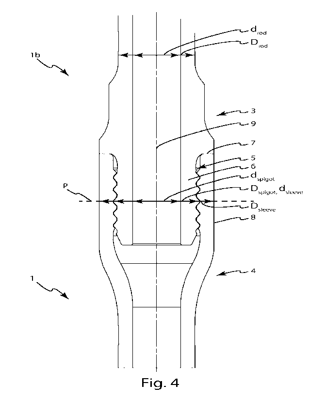
Fig. 4 shows a cross-sectional side view of the sleeve portion and the
spigot of the two connected drill string rods also shown in Fig. 1, said cross-
section taken in a plane through the longitudinal central axis of the drill
string
rod.
1 drill string rod 9 longitudinal axis of drill
string rod
further drill string rod of same
system/assembly of a plurality of drill
lb type 10 string rods
plane defining cross sections for
2 central rod portion P determining Cspigot and
Csleeve
3 male end
drod inner diameter of rod / first diameter
4 female end
Drpd outer diameter of rod / second diameter
5 spigot Dspigot outer diameter or spigot
/ third diameter
6 base (of spigot) dspigot inner diameter of spigot
/ fourth diameter
outer diameter of sleeve portion / fifth
7 shoulder D sleeve diameter
inner diameter of sleeve portion / sixth
8 sleeve portion dsleeve diameter
Diameter of hole drilled /seventh
Dhole diameter
CA 03189258 2023- 2- 13
WO 2022/058420
PCT/EP2021/075470
6
Detailed description
A first embodiment of the invention is shown in Figs. 1-4. As shown
in the figures, a plurality of identical drill string rods 1, lb are
connectable to
form a system/assembly 10. The drill string rod 1 comprises an elongate
central rod portion 2 extending axially between a male end 3 and a female
end 4. As shown in Fig. 4, the central rod portion 2 is hollow-cylindrical
defined by an inner first diameter drod and an outer second diameter Drod. The
male end 3 comprises a spigot 5, and the spigot 5 comprises a base 6
projecting axially from a shoulder 7 that axially separates the spigot 5 and
the
central rod portion 2. The female end 4 comprises a sleeve/sleeve portion 8
configured to fit to the spigot 5. The base 6 is provided with an outer thread
and the sleeve portion 8 is provided with an inner thread, wherein the inner
thread corresponds to the outer thread such that the inner thread of the
sleeve portion 8 is attachable to the outer thread of the base 6 of the spigot
5
of a further drill string rod of the assembly. In a radial plane P to the
longitudinal axis of the drill string rod the base 6 of the spigot 5 is
defined by
an outer third diameter (Dspigot) and an inner fourth diameter (dspigot) and
the
sleeve portion 8 is defined by an outer fifth diameter (Dsleeve) and an inner
sixth diameter (dsleeve). It should be noted that in Fig. 4, Dspigot and
dsleeve are
both mentioned in connection with the same arrow although in reality the
diameters are slightly different with dsieeve being larger than Dspigot. The
scale
of the drawing is such that the difference in diameter cannot be shown in Fig.
4 using separate arrows. Although the diameters may vary along the length of
the spigot and the sleeve portion respectively, the radial plane P
which by necessity runs through both the spigot and the sleeve portion, is
used to define the relationship between the diameters in an unambiguous
way. The present invention is limited to drill string rods with an outer
diameter
between 30 and 60 mm, preferably between 40 and 60 mm such as drill bits
having a diameter of 54 -127 mm. Hence, the second diameter (Drod) is
between 30 - 60 mm, preferably between 40 ¨ 60 mm. Csieeve and Cspigot are
CA 03189258 2023- 2- 13
WO 2022/058420
PCT/EP2021/075470
7
derivable from/related to the diameters of the drill string rod using the
following formulas:
These formulas stem from the calculation of section modulus for
5 hollow-cylindrical beams/bodies which provide a good approximation of the
present involved cross-sectional shapes. Specifically, the section modulus
equations for hollow-cylindrical cross-sections is:
D rod = (D.4sleeve dsleeve)
'-'sleeve
'-'sleeve= (zi 4
'rod "-rod)
D rod = (Ds4 4
pigot d,spigot)
C -
spigot
Dspigot = '.-"rod od C14
rod)
74. (1 w(c11
S
4r2 32d2
Fig 5 shows a section modulus hollow round center neutral.
10 Our assumption is that:
7T(D:pigot¨d'slpiqot) Tr(Dr4od ¨dr4od)
Sspigot Cspigot *Srod 7-7 32*Drod * uspigot
32*Dsptgoe
Drod*(4pigot¨c4pigot)
Cspigot
DsTiflot-0;tod-4.,,d)
And similarly that Ssleeve=Csleeve*Srod =
D rod = (Nieeve dsleeve)
Csleeve = n
L./sleeve = (D4 rod d4
rod)
In this embodiment, the first diameter drod is 30 mm, wherein the
second diameter Drod is 57 mm, wherein the third diameter Dspigot is 48 mm,
CA 03189258 2023- 2- 13 SUBSTITUTE SHEET (RULE 26)
WO 2022/058420
PCT/EP2021/075470
8
wherein the fourth diameter dspigot is 21 mm, wherein the firth diameter
Dsieeve is
76 mm and wherein the sixth diameter dsleeve is 51 mm.
This embodiment of the drill string rod 1, lb is suitable for use with a
drill bit (not illustrated) having a specified diameter (the diameter not
including
the drilling inserts) of 54, 57, 64 70, 76, 89, 102, 115 or 127 mm. The actual
diameter of the holes drilled is slightly larger since the drill bits protrude
radially. The first through sixth diameters may in other embodiments be
chosen differently, as long as the second diameter Drod, which defines the
outer diameter of the central rod portion 2, fulfills the above constraint of
being between 30 and 60 mm, and the other diameters fulfil the constraints
that Csieeve is larger than 2.0 or that Cspigot is larger than 0.6.
Preferably, Csieeve
is larger than 2.0 and Cspigot is larger than 0.6.
The drill string rods are made of a suitable material, such as steel, and
are hardened as needed.
The drill string rod 1, lb is dimensioned based on the size of the drill
bit for which it is to be used. However, care must be taken to provide enough
space around the sleeve portion 8 for drill cuttings to be flushed past the
sleeve portion 8. To this effect, the drill string rod 1, lb may in some
embodiments be suitable for use with a drill bit having an outer seventh
diameter Dhoie, wherein the outer fifth diameter Dsleeve of the sleeve portion
8
is less than 0,90* the seventh diameter Dhoie.
A plurality of identical drill string rods 1, lb may be provided together
as part of a system/assembly 10 of the drill string rods 1, lb. The system 10
may alternatively comprise a drill bit. The drill string rods 1, lb of the
system
10 may have an outer seventh diameter Dhoie, wherein the fifth diameter is <
0,90* the seventh diameter Dhoie, and wherein the system further comprises
the drill bit.
The difference in diameter between the hole and the outer fifth
diameter Dsleeve of the sleeve portion 8 enables efficient flushing of drill
cuttings past the sleeve portion 8, whilst providing robust drill string rods
1, lb
capable of handling the forces involved.
CA 03189258 2023- 2- 13
WO 2022/058420
PCT/EP2021/075470
9
In some embodiments, the seventh diameter Dhoie may be 54 -127
mm. As mentioned above, the drill string rods of the present invention all
have
a second diameter between 30 and 60 mm, preferably between 40 and 60
mmThe specified constraints of the involved diameters given by Csieeve and
Cspigot provide for a robust system/assembly 10.
CA 03189258 2023- 2- 13