Note: Descriptions are shown in the official language in which they were submitted.
CA 03190116 2023-01-24
WO 2022/019918 PCT/US2020/043423
INTEGRATION OF GEOTAGS AND OPPORTUNITY MATURATION
Background
[0001] In oil and gas exploration, geoscientists use paper or electronic
documents to annotate
their findings about a particular region or location. The findings are then
correlated manually with
areas of similar geologic settings thus helping them to explain the
characteristics of the exploratory
target. These areas of similar geologic setting are also called geologic
analogs.
[0002] This traditional approach generally captures a portion of the knowledge
the geoscientist
may wish to save, while some is lost because of the technical constraints
provided by marking the
location of interest on paper or as a location in an electronic file.
Furthermore, these markings may
be confined to the media in which they have been prepared, e.g., to the paper
document on which
they were marked or within the program that has been used to generate the
location information.
As a result, such location notes remain inaccessible to digital search
engines, which can reduce the
distribution of knowledge about a particular location.
[0003] The knowledge gleaned about a particular location, which may be ever-
evolving as more
information is received, additional processing is conducted, etc., may be used
to evaluate the
likelihood of success (e.g., with success being the economical extraction of
hydrocarbons from a
location). However, because knowledge may not be shared and analogs may be
difficult to identify,
there is often a large amount of guesswork involved in establishing such a
likelihood of success,
which is generally considered part of the "risking" process as it is known.
The guesswork, usually
conducted by subject matter experts may thus have a degree of uncertainty,
which may be large,
but is generally unknown. Accordingly, the risking numbers may be difficult to
rely on.
Summary
[0004] Embodiments of the disclosure provide a method that includes obtaining
data
representing a subterranean domain, identifying a candidate location in the
subterranean domain
based on the data, creating a geotag associated with the candidate location,
and storing metadata
in association with the geotag. The metadata describes the geotag, the data at
or around the
location, or both. The method also includes performing an opportunity
maturation process to
evaluate the candidate location for selection as a well location, storing a
result of the opportunity
1
CA 03190116 2023-01-24
WO 2022/019918 PCT/US2020/043423
maturation process as additional metadata associated with the geotag, and
selecting the candidate
location as the well location based in part on the opportunity maturation
process.
[0005] Embodiments of the disclosure also provide a computer system including
one or more
processors, and a memory system including one or more non-transitory computer-
readable media
storing instructions that, when executed by at least one of the one or more
processors, cause the
computer system to perform operations. The operations include obtaining data
representing a
subterranean domain, identifying a candidate location in the subterranean
domain based on the
data, creating a geotag associated with the candidate location, and storing
metadata in association
with the geotag. The metadata describes the geotag, the data at or around the
location, or both. The
operations also include performing an opportunity maturation process to
evaluate the candidate
location for selection as a well location, storing a result of the opportunity
maturation process as
additional metadata associated with the geotag, and selecting the candidate
location as the well
location based in part on the opportunity maturation process.
[0006] Embodiments of the disclosure further provide a non-transitory computer-
readable
medium storing instructions that, when executed by at least one processor of a
computing system,
cause the computing system to perform operations. The operations include
obtaining data
representing a subterranean domain, identifying a candidate location in the
subterranean domain
based on the data, creating a geotag associated with the candidate location,
and storing metadata
in association with the geotag. The metadata describes the geotag, the data at
or around the
location, or both. The operations also include performing an opportunity
maturation process to
evaluate the candidate location for selection as a well location, storing a
result of the opportunity
maturation process as additional metadata associated with the geotag, and
selecting the candidate
location as the well location based in part on the opportunity maturation
process.
[0007] This summary is provided to introduce a selection of concepts that are
further described
below in the detailed description. This summary is not intended to identify
key or essential features
of the claimed subject matter, nor is it intended to be used as an aid in
limiting the scope of the
claimed subject matter.
2
CA 03190116 2023-01-24
WO 2022/019918 PCT/US2020/043423
Brief Description of the Drawings
[0008] The accompanying drawings, which are incorporated in and constitute a
part of this
specification, illustrate embodiments of the present teachings and together
with the description,
serve to explain the principles of the present teachings. In the figures:
[0009] Figures 1A, 1B, 1C, 1D,2, 3A, and 3B illustrate simplified, schematic
views of an oilfield
and its operation, according to an embodiment.
[0010] Figure 4 illustrates a block diagram of a geotagging system, according
to an embodiment.
[0011] Figure 5 illustrates a block diagram of a system for integrating
geotags with an
opportunity pipeline, according to an embodiment
[0012] Figure 6 illustrates another conceptual view of a geotag having
metadata that is updated
or appended as part of an opportunity maturation process, according to an
embodiment.
[0013] Figure 7 illustrates a flowchart of a method for selecting a well
location from candidate
locations using geotags and an opportunity maturation process, according to an
embodiment.
[0014] Figure 8 illustrates a schematic view of a computing system, according
to an
embodiment.
Description of Embodiments
[0015] Reference will now be made in detail to embodiments, examples of which
are illustrated
in the accompanying drawings and figures. In the following detailed
description, numerous
specific details are set forth in order to provide a thorough understanding of
the disclosure.
However, it will be apparent to one of ordinary skill in the art that the
disclosure may be practiced
without these specific details. In other instances, well-known methods,
procedures, components,
circuits and networks have not been described in detail so as not to
unnecessarily obscure aspects
of the embodiments.
[0016] It will also be understood that, although the terms first, second, etc.
may be used herein
to describe various elements, these elements should not be limited by these
terms. These terms are
only used to distinguish one element from another. For example, a first object
could be termed a
second object, and, similarly, a second object could be termed a first object,
without departing
from the scope of the disclosure. The first object and the second object are
both objects,
respectively, but they are not to be considered the same object.
3
CA 03190116 2023-01-24
WO 2022/019918 PCT/US2020/043423
[0017] The terminology used in the description of the disclosure herein is for
the purpose of
describing particular embodiments only and is not intended to be limiting of
the disclosure. As
used in the description of the disclosure and the appended claims, the
singular forms "a," "an" and
"the" are intended to include the plural forms as well, unless the context
clearly indicates
otherwise. It will also be understood that the term "and/or" as used herein
refers to and
encompasses any possible combinations of one or more of the associated listed
items. It will be
further understood that the terms "includes," "including," "comprises" and/or
"comprising," when
used in this specification, specify the presence of stated features, integers,
steps, operations,
elements, and/or components, but do not preclude the presence or addition of
one or more other
features, integers, steps, operations, elements, components, and/or groups
thereof. Further, as used
herein, the term "if" may be construed to mean "when" or "upon" or "in
response to determining"
or "in response to detecting," depending on the context.
[0018] Attention is now directed to processing procedures, methods, techniques
and workflows
that are in accordance with some embodiments. Some operations in the
processing procedures,
methods, techniques and workflows disclosed herein may be combined and/or the
order of some
operations may be changed.
[0019] Figures 1A-1D illustrate simplified, schematic views of oilfield 100
having subterranean
formation 102 containing reservoir 104 therein in accordance with
implementations of various
technologies and techniques described herein. Figure 1A illustrates a survey
operation being
performed by a survey tool, such as seismic truck 106.1, to measure properties
of the subterranean
formation. The survey operation is a seismic survey operation for producing
sound vibrations. In
Figure 1A, one such sound vibration, e.g., sound vibration 112 generated by
source 110, reflects
off horizons 114 in earth formation 116. A set of sound vibrations is received
by sensors, such as
geophone-receivers 118, situated on the earth's surface. The data received 120
is provided as input
data to a computer 122.1 of a seismic truck 106.1, and responsive to the input
data, computer 122.1
generates seismic data output 124. This seismic data output may be stored,
transmitted or further
processed as desired, for example, by data reduction.
[0020] Figure 1B illustrates a drilling operation being performed by drilling
tools 106.2
suspended by rig 128 and advanced into subterranean formations 102 to form
wellbore 136. Mud
pit 130 is used to draw drilling mud into the drilling tools via flow line 132
for circulating drilling
mud down through the drilling tools, then up wellbore 136 and back to the
surface. The drilling
4
CA 03190116 2023-01-24
WO 2022/019918 PCT/US2020/043423
mud is typically filtered and returned to the mud pit. A circulating system
may be used for storing,
controlling, or filtering the flowing drilling mud. The drilling tools are
advanced into subterranean
formations 102 to reach reservoir 104. Each well may target one or more
reservoirs. The drilling
tools are adapted for measuring downhole properties using logging while
drilling tools. The
logging while drilling tools may also be adapted for taking core sample 133 as
shown.
[0021] Computer facilities may be positioned at various locations about the
oilfield 100 (e.g.,
the surface unit 134) and/or at remote locations. Surface unit 134 may be used
to communicate
with the drilling tools and/or offsite operations, as well as with other
surface or downhole sensors.
Surface unit 134 is capable of communicating with the drilling tools to send
commands to the
drilling tools, and to receive data therefrom. Surface unit 134 may also
collect data generated
during the drilling operation and produce data output 135, which may then be
stored or transmitted.
[0022] Sensors (S), such as gauges, may be positioned about oilfield 100 to
collect data relating
to various oilfield operations as described previously. As shown, sensor (S)
is positioned in one or
more locations in the drilling tools and/or at rig 128 to measure drilling
parameters, such as weight
on bit, torque on bit, pressures, temperatures, flow rates, compositions,
rotary speed, and/or other
parameters of the field operation. Sensors (S) may also be positioned in one
or more locations in
the circulating system.
[0023] Drilling tools 106.2 may include a bottom hole assembly (BHA) (not
shown), generally
referenced, near the drill bit (e.g., within several drill collar lengths from
the drill bit). The bottom
hole assembly includes capabilities for measuring, processing, and storing
information, as well as
communicating with surface unit 134. The bottom hole assembly further includes
drill collars for
performing various other measurement functions.
[0024] The bottom hole assembly may include a communication subassembly that
communicates with surface unit 134. The communication subassembly is adapted
to send signals
to and receive signals from the surface using a communications channel such as
mud pulse
telemetry, electro-magnetic telemetry, or wired drill pipe communications. The
communication
subassembly may include, for example, a transmitter that generates a signal,
such as an acoustic
or electromagnetic signal, which is representative of the measured drilling
parameters. It will be
appreciated by one of skill in the art that a variety of telemetry systems may
be employed, such as
wired drill pipe, electromagnetic or other known telemetry systems.
CA 03190116 2023-01-24
WO 2022/019918 PCT/US2020/043423
[0025] Typically, the wellbore is drilled according to a drilling plan that is
established prior to
drilling. The drilling plan typically sets forth equipment, pressures,
trajectories and/or other
parameters that define the drilling process for the wellsite. The drilling
operation may then be
performed according to the drilling plan. However, as information is gathered,
the drilling
operation may need to deviate from the drilling plan. Additionally, as
drilling or other operations
are performed, the subsurface conditions may change. The earth model may also
need adjustment
as new information is collected
[0026] The data gathered by sensors (S) may be collected by surface unit 134
and/or other data
collection sources for analysis or other processing. The data collected by
sensors (S) may be used
alone or in combination with other data. The data may be collected in one or
more databases and/or
transmitted on or offsite. The data may be historical data, real time data, or
combinations thereof.
The real time data may be used in real time, or stored for later use. The data
may also be combined
with historical data or other inputs for further analysis. The data may be
stored in separate
databases, or combined into a single database.
[0027] Surface unit 134 may include transceiver 137 to allow communications
between surface
unit 134 and various portions of the oilfield 100 or other locations. Surface
unit 134 may also be
provided with or functionally connected to one or more controllers (not shown)
for actuating
mechanisms at oilfield 100. Surface unit 134 may then send command signals to
oilfield 100 in
response to data received. Surface unit 134 may receive commands via
transceiver 137 or may
itself execute commands to the controller. A processor may be provided to
analyze the data (locally
or remotely), make the decisions and/or actuate the controller. In this
manner, oilfield 100 may be
selectively adjusted based on the data collected. This technique may be used
to optimize (or
improve) portions of the field operation, such as controlling drilling, weight
on bit, pump rates, or
other parameters. These adjustments may be made automatically based on
computer protocol,
and/or manually by an operator. In some cases, well plans may be adjusted to
select optimum (or
improved) operating conditions, or to avoid problems.
[0028] Figure 1C illustrates a wireline operation being performed by wireline
tool 106.3
suspended by rig 128 and into wellbore 136 of Figure 1B. Wireline tool 106.3
is adapted for
deployment into wellbore 136 for generating well logs, performing downhole
tests and/or
collecting samples. Wireline tool 106.3 may be used to provide another method
and apparatus for
performing a seismic survey operation. Wireline tool 106.3 may, for example,
have an explosive,
6
CA 03190116 2023-01-24
WO 2022/019918 PCT/US2020/043423
radioactive, electrical, or acoustic energy source 144 that sends and/or
receives electrical signals
to surrounding subterranean formations 102 and fluids therein.
[0029] Wireline tool 106.3 may be operatively connected to, for example,
geophones 118 and a
computer 122.1 of a seismic truck 106.1 of Figure 1A. Wireline tool 106.3 may
also provide data
to surface unit 134. Surface unit 134 may collect data generated during the
wireline operation and
may produce data output 135 that may be stored or transmitted. Wireline tool
106.3 may be
positioned at various depths in the wellbore 136 to provide a survey or other
information relating
to the subterranean formation 102.
[0030] Sensors (S), such as gauges, may be positioned about oilfield 100 to
collect data relating
to various field operations as described previously. As shown, sensor S is
positioned in wireline
tool 106.3 to measure downhole parameters which relate to, for example
porosity, permeability,
fluid composition and/or other parameters of the field operation.
[0031] Figure 1D illustrates a production operation being performed by
production tool 106.4
deployed from a production unit or Christmas tree 129 and into completed
wellbore 136 for
drawing fluid from the downhole reservoirs into surface facilities 142. The
fluid flows from
reservoir 104 through perforations in the casing (not shown) and into
production tool 106.4 in
wellbore 136 and to surface facilities 142 via gathering network 146.
[0032] Sensors (S), such as gauges, may be positioned about oilfield 100 to
collect data relating
to various field operations as described previously. As shown, the sensor (S)
may be positioned in
production tool 106.4 or associated equipment, such as Christmas tree 129,
gathering network 146,
surface facility 142, and/or the production facility, to measure fluid
parameters, such as fluid
composition, flow rates, pressures, temperatures, and/or other parameters of
the production
operation.
[0033] Production may also include injection wells for added recovery. One or
more gathering
facilities may be operatively connected to one or more of the wellsites for
selectively collecting
downhole fluids from the wellsite(s).
[0034] While Figures 1B-1D illustrate tools used to measure properties of an
oilfield, it will be
appreciated that the tools may be used in connection with non-oilfield
operations, such as gas
fields, mines, aquifers, storage or other subterranean facilities. Also, while
certain data acquisition
tools are depicted, it will be appreciated that various measurement tools
capable of sensing
parameters, such as seismic two-way travel time, density, resistivity,
production rate, etc., of the
7
CA 03190116 2023-01-24
WO 2022/019918 PCT/US2020/043423
subterranean formation and/or its geological formations may be used. Various
sensors (S) may be
located at various positions along the wellbore and/or the monitoring tools to
collect and/or
monitor the desired data. Other sources of data may also be provided from
offsite locations.
[0035] The field configurations of Figures 1A-1D are intended to provide a
brief description of
an example of a field usable with oilfield application frameworks. Part of, or
the entirety, of oilfield
100 may be on land, water and/or sea. Also, while a single field measured at a
single location is
depicted, oilfield applications may be utilized with any combination of one or
more oilfields, one
or more processing facilities and one or more wellsites.
[0036] Figure 2 illustrates a schematic view, partially in cross section of
oilfield 200 having data
acquisition tools 202.1, 202.2, 202.3 and 202.4 positioned at various
locations along oilfield 200
for collecting data of subterranean formation 204 in accordance with
implementations of various
technologies and techniques described herein. Data acquisition tools 202.1-
202.4 may be the same
as data acquisition tools 106.1-106.4 of Figures 1A-1D, respectively, or
others not depicted. As
shown, data acquisition tools 202.1-202.4 generate data plots or measurements
208.1-208.4,
respectively. These data plots are depicted along oilfield 200 to demonstrate
the data generated by
the various operations.
[0037] Data plots 208.1-208.3 are examples of static data plots that may be
generated by data
acquisition tools 202.1-202.3, respectively; however, it should be understood
that data plots 208.1-
208.3 may also be data plots that are updated in real time. These measurements
may be analyzed
to better define the properties of the formation(s) and/or determine the
accuracy of the
measurements and/or for checking for errors. The plots of each of the
respective measurements
may be aligned and scaled for comparison and verification of the properties.
[0038] Static data plot 208.1 is a seismic two-way response over a period of
time. Static plot
208.2 is core sample data measured from a core sample of the formation 204.
The core sample
may be used to provide data, such as a graph of the density, porosity,
permeability, or some other
physical property of the core sample over the length of the core. Tests for
density and viscosity
may be performed on the fluids in the core at varying pressures and
temperatures. Static data plot
208.3 is a logging trace that typically provides a resistivity or other
measurement of the formation
at various depths.
[0039] A production decline curve or graph 208.4 is a dynamic data plot of the
fluid flow rate
over time. The production decline curve typically provides the production rate
as a function of
8
CA 03190116 2023-01-24
WO 2022/019918 PCT/US2020/043423
time. As the fluid flows through the wellbore, measurements are taken of fluid
properties, such as
flow rates, pressures, composition, etc.
[0040] Other data may also be collected, such as historical data, user inputs,
economic
information, and/or other measurement data and other parameters of interest.
As described below,
the static and dynamic measurements may be analyzed and used to generate
models of the
subterranean formation to determine characteristics thereof. Similar
measurements may also be
used to measure changes in formation aspects over time.
[0041] The subterranean structure 204 has a plurality of geological formations
206.1-206.4. As
shown, this structure has several formations or layers, including a shale
layer 206.1, a carbonate
layer 206.2, a shale layer 206.3 and a sand layer 206.4. A fault 207 extends
through the shale layer
206.1 and the carbonate layer 206.2. The static data acquisition tools are
adapted to take
measurements and detect characteristics of the formations.
[0042] While a specific subterranean formation with specific geological
structures is depicted,
it will be appreciated that oilfield 200 may contain a variety of geological
structures and/or
formations, sometimes having extreme complexity. In some locations, typically
below the water
line, fluid may occupy pore spaces of the formations. Each of the measurement
devices may be
used to measure properties of the formations and/or its geological features.
While each acquisition
tool is shown as being in specific locations in oilfield 200, it will be
appreciated that one or more
types of measurement may be taken at one or more locations across one or more
fields or other
locations for comparison and/or analysis.
[0043] The data collected from various sources, such as the data acquisition
tools of Figure 2,
may then be processed and/or evaluated. Typically, seismic data displayed in
static data plot 208.1
from data acquisition tool 202.1 is used by a geophysicist to determine
characteristics of the
subterranean formations and features. The core data shown in static plot 208.2
and/or log data from
well log 208.3 are typically used by a geologist to determine various
characteristics of the
subterranean formation. The production data from graph 208.4 is typically used
by the reservoir
engineer to determine fluid flow reservoir characteristics. The data analyzed
by the geologist,
geophysicist and the reservoir engineer may be analyzed using modeling
techniques.
[0044] Figure 3A illustrates an oilfield 300 for performing production
operations in accordance
with implementations of various technologies and techniques described herein.
As shown, the
oilfield has a plurality of wellsites 302 operatively connected to central
processing facility 354.
9
CA 03190116 2023-01-24
WO 2022/019918 PCT/US2020/043423
The oilfield configuration of Figure 3A is not intended to limit the scope of
the oilfield application
system. Part, or all, of the oilfield may be on land and/or sea. Also, while a
single oilfield with a
single processing facility and a plurality of wellsites is depicted, any
combination of one or more
oilfields, one or more processing facilities and one or more wellsites may be
present. In the
illustrates, marine example, the environment may include a sea surface 376 and
a seafloor surface
364.
[0045] Each wellsite 302 has equipment that forms wellbore 336 into the earth.
The wellbores
extend through subterranean formations 306 including reservoirs 304. These
reservoirs 304
contain fluids, such as hydrocarbons. The wellsites draw fluid from the
reservoirs and pass them
to the processing facilities via surface networks 344. The surface networks
344 have tubing and
control mechanisms for controlling the flow of fluids from the wellsite to
processing facility 354.
[0046] Attention is now directed to Figure 3B, which illustrates a side view
of a marine-based
survey 360 of a subterranean subsurface 362 in accordance with one or more
implementations of
various techniques described herein. Seismic sources 366 may include marine
sources such as
vibroseis or airguns, which may propagate seismic waves 368 (e.g., energy
signals) into the Earth
over an extended period of time or at a nearly instantaneous energy provided
by impulsive sources.
The seismic waves may be propagated by marine sources as a frequency sweep
signal. For
example, marine sources of the vibroseis type may initially emit a seismic
wave at a low frequency
(e.g., 5 Hz) and increase the seismic wave to a high frequency (e.g., 80-90Hz)
over time.
[0047] The component(s) of the seismic waves 368 may be reflected and
converted by seafloor
surface 364 (i.e., reflector), and seismic wave reflections 370 may be
received by a plurality of
seismic receivers 372. Seismic receivers 372 may be disposed on a plurality of
streamers (i.e.,
streamer array 374). The seismic receivers 372 may generate electrical signals
representative of
the received seismic wave reflections 370. The electrical signals may be
embedded with
information regarding the subsurface 362 and captured as a record of seismic
data.
[0048] In one implementation, each streamer may include streamer steering
devices such as a
bird, a deflector, a tail buoy and the like, which are not illustrated in this
application. The streamer
steering devices may be used to control the position of the streamers in
accordance with the
techniques described herein.
[0049] In one implementation, seismic wave reflections 370 may travel upward
and reach the
water/air interface at the sea surface 376, a portion of reflections 370 may
then reflect downward
CA 03190116 2023-01-24
WO 2022/019918 PCT/US2020/043423
again (i.e., sea-surface ghost waves 378) and be received by the plurality of
seismic receivers 372.
The sea-surface ghost waves 378 may be referred to as surface multiples. The
point on the water
surface 376 at which the wave is reflected downward is generally referred to
as the downward
reflection point.
[0050] The electrical signals may be transmitted to a vessel 380 via
transmission cables, wireless
communication or the like. The vessel 380 may then transmit the electrical
signals to a data
processing center. Alternatively, the vessel 380 may include an onboard
computer capable of
processing the electrical signals (i.e., seismic data). Those skilled in the
art having the benefit of
this disclosure will appreciate that this illustration is highly idealized.
For instance, surveys may
be of formations deep beneath the surface. The formations may typically
include multiple
reflectors, some of which may include dipping events, and may generate
multiple reflections
(including wave conversion) for receipt by the seismic receivers 372. In one
implementation, the
seismic data may be processed to generate a seismic image of the subsurface
362.
[0051] Marine seismic acquisition systems tow each streamer in streamer array
374 at the same
depth (e.g., 5-10m). However, marine based survey 360 may tow each streamer in
streamer array
374 at different depths such that seismic data may be acquired and processed
in a manner that
avoids the effects of destructive interference due to sea-surface ghost waves.
For instance, marine-
based survey 360 of Figure 3B illustrates eight streamers towed by vessel 380
at eight different
depths. The depth of each streamer may be controlled and maintained using the
birds disposed on
each streamer.
[0052] Embodiments of the present disclosure generally include systems and
methods for
creating, refining, and using digital markers ("geotags") in an oilfield
exploration, drilling, and
production environment. The geotags are used to store information about a
location, and may be
displayed as a dynamic link within a visualization of the data representing
the subterranean volume
of data. The geotags may be employed to capture knowledge acquired during the
process of
processing, analysis, interpretation, and modeling when labelling
opportunities in a resource
exploration workflow. These geotags are created and stored in a distributed
computing (e.g., cloud-
based) process by geoscientists working with data and models and may include
metadata
information about origin, location, and geoscientific characteristics of a
spatial location in depth
and geological time. The metadata may be provided by humans and/or artificial
intelligence (AI)
based on interpretation or by digital processes using digital processing and
interpretation of the
11
CA 03190116 2023-01-24
WO 2022/019918 PCT/US2020/043423
data. The amount of information and knowledge collected in the geotags
increases with the
maturation of the tagged location during an "opportunity maturation" process,
which includes
assigning risk (or conversely, a likelihood of success) to a location, whereby
locations with good
chances of success may develop from a candidate, to a lead, a prospect, a
drilling location, or even
a well location.
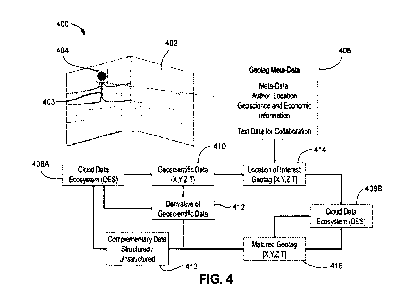
[0053] Figure 4 illustrates a functional block diagram of a geotagging system
400, according to
an embodiment. The geotagging system 400 may include data representing a
subterranean volume
402. The data representing the subterranean volume 402 may be obtained from
one or more of a
variety of sources, including seismic, core samples, well logs, etc. The
volume 402 may include
one or more features 403, such as an anticline, to name one specific example.
The feature 403 may
indicate an area where hydrocarbons may, potentially, be located and thus may
be of interest to
users. Accordingly, a geotag 404 may be generated to mark the feature 403 in
the volume 402.
[0054] The geotag 404 may not be a static part of the data (e.g., the image)
of the volume 402.
For example, the geotag 404 may be stored in a database in association with
the location (which
may include horizontal, depth, and/or time dimensions). In some embodiments, a
larger, e.g., map-
based view of an area may be available, and a user may manipulate the view
until a region of
interest is created on the screen, which may include subsurface regions. When
the screen includes
the location corresponding to the geotag 404, the geotag 404 may be displayed.
As such, the geotag
404 may be stored and displayed when its location is part of the current view,
e.g., within a certain
resolution, etc.
[0055] The geotag 404 may, in addition to its location in the volume 402,
store various metadata,
as indicated at 406, e.g., in a database. This metadata 406 may at least
partially describe the
location of interest, even if indirectly (e.g., it may refer to the political
climate of the general area
in which the geotag 404 is located, industry activity in the area, economic
conditions, etc.). The
metadata 406 may include, for example, a name, date, location and affiliation
of the author of the
geotag; a location component such as coordinates, depth, corresponding
geological time; a data
component including a description of data set(s) and interpretation using
which the geotag was
generated and/or settings of analysis window at the time of creating the
geotag; a petroleum system
component including information regarding the petroleum system elements
identified at the
location of the geotag including among others source and maturation of
hydrocarbons, migration
pathway, reservoir, seal, trap, retention, and play; a geology component
including modern and
12
CA 03190116 2023-01-24
WO 2022/019918 PCT/US2020/043423
(geologically) historic structural and stratigraphic setting, geologic age,
sequence stratigraphic
description, lithology; a risking component including risking parameters,
information about
chance of success for petroleum system elements; a petroleum economics
component including
legislation, block / concession and operatorship, information regarding field,
its development
status including infrastructure, and production; and a drilling component:
information regarding
pressure, well planning and completion.
[0056] The geotag metadata 406 may be stored in a cloud data ecosystem (DES),
which may be
represented as two ecosystems 408A, 408B in this view, but may also be
considered a single DES
in some embodiments. The DES 408A, 408B may store the data according to
various schemas in
different locations throughout a computing system, e.g., on different servers
that are remotely
accessible, etc. The metadata 406 may be geoscientific data 410 and may be
stored according to
coordinates within the volume 402, e.g., X, Y, Z (depth), and/or T (time).
Derivatives 412 of the
geoscientific data 410 may be developed, e.g., through processing techniques,
which permit
additional information, inferences, etc. about the subterranean volume 402 to
be made. These
derivatives 412 may be stored in the DES 408A. Further, complementary data
413, which may be
structured (e.g., spreadsheets or forms) or unstructured (e.g., text-based)
may be stored in the DES
408A. In some cases, text-based data may be added by human users as
interpretation notes that
can inform later processing, decision-making, etc.
[0057] At some point, a user may initialize a geotag 404 at a location of
interest 414, as generally
described above. The location of interest may be at a feature, e.g., the
feature 403, as mentioned
above. The location of interest may thus have a coordinate in the volume 402,
e.g., X, Y, Z, and/or
T coordinates, corresponding to the location of the feature 403. The geotag
404 and any metadata
406 associated therewith may thus be stored in the DES 408B for later use,
e.g., through searching,
as will be described in greater detail below. In addition, a matured geotag
418 may also be
produced and stored, e.g., by refining the information stored in combination
with the geotag 404,
e.g., during or after an opportunity maturation processes, as will be
described in greater detail
below. Accordingly, the geotags 404 may be iteratively searched, accessed,
updated, clustered,
split, and otherwise manipulated.
[0058] Figure 5 illustrates a block diagram of a system 500 for integrating
geotags with an
opportunity pipeline, according to an embodiment. An opportunity pipeline
generally describes
the maturation process during which a well site is selected from among many
potential candidates,
13
CA 03190116 2023-01-24
WO 2022/019918 PCT/US2020/043423
researched and analyzed, and ultimately determined to be viable and then
drilled, completed, and
produced. Geotags may be useful in this process to assist in the risking
process, as analogs of
locations (e.g., in geological, structural, drilling, environmental,
political, etc. senses) may be
analyzed and the risking derived based on risking that was previously
completed for these other,
analogous locations.
[0059] Accordingly, the opportunity pipeline may begin by analyzing regional
data, as at 502,
e.g., in order to identify features in the subsurface that may be indicative
of the presence of
hydrocarbons. Geotags may be initiated, e.g., based on features identified in
the regional data, and
metadata 504 associated with the geotags may be updated/appended using the
regional data. The
metadata 504 may include author, location, data, and petroleum system. The
metadata 504 may be
employed to rule out locations that are not of interest, e.g., noise in the
data, locations that have
already been rejected and should not be reconsidered, etc. Locations that
remain of interest may
be candidates 506, which have geotags associated therewith, as shown.
[0060] The system 500 may consider many candidates 506, e.g., hundreds,
thousands, or more,
and thus the regional data 502 and metadata 504 associated with geotags
therein may be employed
to quickly winnow down the number of candidates 506, e.g., ruling out
candidates that may not be
worth additional analysis. It will be appreciated, however, that these
candidates 506 may not be
discarded, as changing information make change the value of the candidates 506
at a later time.
To do this, the system 500 may consider local (e.g., geologic) data, as at
510, and with results
thereof describing the geology of the candidates 506 and being stored in
metadata as at 512. The
system 500 may also search through a database of geotags to identify analogs
that may inform the
opportunity maturation process, as will be described in greater detail below.
If the geologic
information of the local geotags, along with what is known about the location
of interested
associated with a lead geotag, indicates that the candidate location has
favorable conditions, e.g.,
for the storage of hydrocarbons, the candidate may be upgraded to a lead at
514; otherwise, the
candidate 506 may be ruled out or otherwise discarded, and any geotags
associated therewith may
be updated to include that the candidate 506 was ruled out.
[0061] The leads 516 may be evaluated based on a risking analysis, as at block
520. The risking
analysis 520 may gather available information about the location of interest,
along with any
information known about analogous locations from searching through the
geotags, including
previously calculated risking for those analogous locations (e.g., in a
database of geotags), which
14
CA 03190116 2023-01-24
WO 2022/019918 PCT/US2020/043423
is stored in association with the geotags for the analogous locations, as
indicated at 522. The risking
analysis 520 may then be applied to the prospect to establish a quantitative
risk that drilling,
production, etc., is ultimately unsuccessful (e.g., no economically-produced
hydrocarbons). If the
risk value applied by the risking analysis above a risk-tolerance threshold,
the lead 514 may be
discarded. Otherwise, the lead 516 may be considered as a prospect 524.
[0062] The prospects 524 may be evaluated based on economics, as at 530. This
may include a
multitude of factors, including the drilling/production equipment that is
usable for the location
530, amount of hydrocarbons thought to be present in the reservoir, as well as
the transportation
costs for the particular prospect 524, and treatment/injection process that
may be prescribed as part
of a plan to drill the well at the prospect 524. The metadata of analogous
geotags may also be
considered, especially the petroleum system elements and economics components
thereof. There
result of the economic analysis (including analogous geotags) may be stored as
metadata at 532.
If a prospect 524 is found to be economically viable, it may be considered for
a drilling location
534.
[0063] Drilling locations 534 may be evaluated to make a drilling decision, as
at 540. Drilling
data, e.g., well plans, geometry, rig equipment, etc., may be obtained, and
considered in view of
the data about the subterranean area and/or for analogous geotags, as at 532.
Once a drilling
location 534 is selected, a well may be constructed, completed, produced, and
eventually
abandoned as part of its lifecycle. The geotag(s) associated with the well
location may be updated
along the way, such that subsequent well locations may be selected from among
thousands of
candidates based on the same or similar process.
[0064] Figure 6 illustrates a conceptual view of a system 600 that
integrates the geotags with
the opportunity maturation process (also referred to as an "opportunity
pipeline"), according to an
embodiment. In particular, the system 600 illustrates building and updating
geotag metadata 602
during respective opportunity pipeline stages 602. For example, the geotag
metadata 602 may be
initialized with data fields for author, location, data, petroleum system,
geology, risking, petroleum
economics, and drilling, as shown. As this information becomes known or
refined, it may be added
to the geotag metadata 602 in a manual or automated process. For example,
author and location
may be readily available at initialization. Next, as regional data is
collected (e.g., to analyze a
candidate, as discussed above) at 605, the regional data may be added to the
data fields, petroleum
system fields, and/or geology fields, as shown. Likewise, as local data 606
becomes available (e.g.,
CA 03190116 2023-01-24
WO 2022/019918 PCT/US2020/043423
to identify a lead from a candidate), the local data may be added to the data,
petroleum system,
and/or geology fields, as appropriate.
[0065] When the risking is completed at 608, e.g., for finding a prospect from
a lead, the risking
analysis or results thereof (e.g., a risk value) may be stored in the risking
field. Economics data
610, collected when identifying a drilling location from a prospect, may be
stored in the petroleum
economics field. Drilling data 612, collected while drilling a well, may be
stored in the drilling
field while or after creating a well location. Accordingly, each step in the
opportunity maturation
process may reveal additional metadata about a particular location, which may
or may not affect
the geographic representation of subterranean location associated with the
geotag; however, it may
be useful for subsequent evaluation of similar locations. Accordingly, by
storing the geotags in a
database in association with the metadata 604, this metadata 604 may be
searched to assist in
subsequent processes, e.g., risking, drilling decisions, etc., as they
indicate what was done in other
instances. It will be appreciated that the entire process of the opportunity
pipeline may not be
conducted for each tag, and likely would not be. Rather, the data acquired for
a geotag may be
stored in association therewith in an effort to provide additional data, even
if the entirety of the
metadata is not complete for a given geotag.
[0066] Figure 7 illustrates a flowchart of a method 700, according to an
embodiment. The
method 700 may integrate the opportunity maturation process with the storage
and rapid,
distributed availability of geotags that identify regions, features,
reservoirs, etc., in a subterranean
domain, so as to facilitate the selection of well sites, inform drilling
decisions, etc. The method
700 may include obtaining data representing a subterranean domain, as at 705.
The data may be
any type of data representing the subterranean domain, including well logs,
seismic data, radar,
LiDAR, geologic data, core samples, etc. In some embodiments, the first data
may be visualized
in a three-dimensional map, or in a four-dimensional map that changes with
time; however, in
other embodiments, the first data may be non-image based.
[0067] The method 700 may also include identifying a candidate location in the
subterranean
domain based on the data, as at 710. For example, an anomalous spike in a
signal, an apparent
feature in at a particular depth in a formation, etc., may be examples of
features that may be
associated with a candidate location. In general, a candidate location may be
any location within a
subterranean location that may be, at least initially, considered as favorable
to including
hydrocarbons. In a given region, many candidate locations may be evaluated.
16
CA 03190116 2023-01-24
WO 2022/019918 PCT/US2020/043423
[0068] A geotag may be associated with the candidate location (either before
or after identifying
a location as being a candidate), as at 715. The geotag may be an object in a
database or other type
of memory, that is able to have data (e.g., metadata) stored in association
therewith, such that data
stored "in association with" the geotag is readily retrievable by
identification of the geotag.
Likewise, the geotag may be stored in association with the location in the
sense that the location
is readily identifiable from the geotag. For example, three-dimensional
coordinates may be stored
in association with the geotag, and the coordinates may identify a unique
location within the first
data representing the subterranean domain. In some embodiments, a time
dimension may also be
stored, in addition to the three-dimensional, spatial coordinates. In still
other embodiments, any
varying attribute may be stored as a dimension, in addition to the three-
dimensional, spatial
coordinates.
[0069] In addition to the location data, various metadata may be stored in
association with the
geotag, as at 720. The metadata, which is described in greater detail above,
may describe the
geotag, the first data at or around the candidate location, or both. For
example, the metadata may
provide insight into the author of the geotag and/or the first data, previous
analysis that have been
conducted on the location, opportunity maturation results (described in
greater detail below),
political climate, economic information, costs to transport hydrocarbons,
geological information,
nearby drilling results, etc.
[0070] The method 700 may also include performing an opportunity maturation
process to
evaluate the candidate location as a well location, as at 725. This may be a
multi-stage process, as
described above, and may include, for example, identifying a subset of the
candidates and leads, a
subset of the leads as prospects, a subset of the prospects as drilling
locations, and a subset of the
drilling locations as well locations. Further, the opportunity maturation
process may extend to
production activities and abandonment.
[0071] There may be many potential results for the opportunity maturation
process for an
individual candidate location and associated geotag. For example, local
(geological data) may be
developed as part of the opportunity maturation process and may form one
result thereof, e.g.,
when identifying a lead from a candidate. The opportunity maturation process
may also include a
risking analysis for the leads, the risk value resulting therefrom being one
potential result when
attempting to identify a prospect. The results of an economic analysis of a
prospect may be another
result, which may be used to identify a drilling location from a prospect, and
a drilling decision
17
CA 03190116 2023-01-24
WO 2022/019918 PCT/US2020/043423
may be result arising from determining a well location from a potential
drilling location. Any or
each of these results, if and when they become available, may be stored in
association with the
geotag of the location for which the opportunity maturation process is
applied, e.g., as additional
metadata, as at 730.
[0072] Eventually, one or more candidates may proceed through the opportunity
maturation
process to being selected for drilling, completion, and production as a well.
This well location
selection may be based in part on the opportunity maturation process, as at
735, as non-viable
candidates are ruled out during the process. The well may be visualized in
image-based data, based
on the opportunity maturation process, in order to facilitate users locating
and implementing the
well at the selected location.
[0073] The geotags that are created, along with the metadata that is developed
for these locations
during the opportunity maturation process may be stored in a database of
geotags. The database
may be searchable to identify digital analogs, as at 740. A digital analog may
be a geotag that was
previously created and is associated with a location that is analogous in some
salient respect to a
candidate location that is presently of interest. The location may be
analogous in that it is in the
same petroleum system (e.g., basin), has similar geoscience coordinates,
similar political climate,
similar economics, etc.
[0074] The digital analog geotag may thus be employed to inform the
opportunity maturation
process for a current geotag so as to evaluate a candidate location at any or
each point in the
opportunity maturation process. For example, a result of the opportunity
maturation process in the
digital analog geotag may be used as a reference for the same step in the
opportunity maturation
process in the current geotag. For example, a risking analysis result for an
analogous lead location
may be used to inform the risking analysis being conducted on the current
location. This may
reduce an uncertainty of the risking analysis. As such, the result (which may
be any of the
aforementioned results) of the opportunity maturation process for a digital
analog geotag may be
used to evaluate a current location.
[0075] In an embodiment, various aspects of the geotagging and the opportunity
maturation
process may be visualized, as at 750. Visualizing may include displaying, on a
computer screen,
the first data of the subterranean domain with one or more geotags for
candidate locations therein.
The digital analogs and/or their completeness in the opportunity maturation
process may also be
18
CA 03190116 2023-01-24
WO 2022/019918 PCT/US2020/043423
visualized. This may allow users (including AT, etc.) to quickly select
digital analogs to assist in
the opportunity maturation process.
[0076] In some embodiments, any of the methods of the present disclosure may
be executed by
a computing system. Figure 8 illustrates an example of such a computing system
800, in
accordance with some embodiments. The computing system 800 may include a
computer or
computer system 801A, which may be an individual computer system 801A or an
arrangement of
distributed computer systems. The computer system 801A includes one or more
analysis module(s)
802 configured to perform various tasks according to some embodiments, such as
one or more
methods disclosed herein. To perform these various tasks, the analysis module
802 executes
independently, or in coordination with, one or more processors 804, which is
(or are) connected to
one or more storage media 806. The processor(s) 804 is (or are) also connected
to a network
interface 807 to allow the computer system 801A to communicate over a data
network 809 with
one or more additional computer systems and/or computing systems, such as
801B, 801C, and/or
801D (note that computer systems 801B, 801C and/or 801D may or may not share
the same
architecture as computer system 801A, and may be located in different physical
locations, e.g.,
computer systems 801A and 801B may be located in a processing facility, while
in communication
with one or more computer systems such as 801C and/or 801D that are located in
one or more data
centers, and/or located in varying countries on different continents).
[0077] A processor can include a microprocessor, microcontroller, processor
module or
subsystem, programmable integrated circuit, programmable gate array, or
another control or
computing device.
[0078] The storage media 806 can be implemented as one or more computer-
readable or
machine-readable storage media. Note that while in the example embodiment of
Figure 8 storage
media 806 is depicted as within computer system 801A, in some embodiments,
storage media 806
may be distributed within and/or across multiple internal and/or external
enclosures of computing
system 801A and/or additional computing systems. Storage media 806 may include
one or more
different forms of memory including semiconductor memory devices such as
dynamic or static
random access memories (DRAMs or SRAMs), erasable and programmable read-only
memories
(EPROMs), electrically erasable and programmable read-only memories (EEPROMs)
and flash
memories, magnetic disks such as fixed, floppy and removable disks, other
magnetic media
including tape, optical media such as compact disks (CDs) or digital video
disks (DVDs),
19
CA 03190116 2023-01-24
WO 2022/019918 PCT/US2020/043423
BLURAY disks, or other types of optical storage, or other types of storage
devices. Note that the
instructions discussed above can be provided on one computer-readable or
machine-readable
storage medium, or alternatively, can be provided on multiple computer-
readable or machine-
readable storage media distributed in a large system having possibly plural
nodes. Such computer-
readable or machine-readable storage medium or media is (are) considered to be
part of an article
(or article of manufacture). An article or article of manufacture can refer to
any manufactured
single component or multiple components. The storage medium or media can be
located either in
the machine running the machine-readable instructions or located at a remote
site from which
machine-readable instructions can be downloaded over a network for execution.
[0079] In some embodiments, computing system 800 contains one or more geotag
module(s)
808. In the example of computing system 800, computer system 801A includes the
geotag module
808. In some embodiments, a geotag module 808 may be used to perform some or
all aspects of
one or more embodiments of the methods. In alternate embodiments, a plurality
of geotag modules
808 may be used to perform some or all aspects of methods.
[0080] It should be appreciated that computing system 800 is only one example
of a computing
system, and that computing system 800 may have more or fewer components than
shown, may
combine additional components not depicted in the example embodiment of Figure
8, and/or
computing system 800 may have a different configuration or arrangement of the
components
depicted in Figure 8. The various components shown in Figure 8 may be
implemented in hardware,
software, or a combination of both hardware and software, including one or
more signal processing
and/or application specific integrated circuits.
[0081] Further, the steps in the processing methods described herein may be
implemented by
running one or more functional modules in information processing apparatus
such as general
purpose processors or application specific chips, such as ASICs, FPGAs, PLDs,
or other
appropriate devices. These modules, combinations of these modules, and/or
their combination with
general hardware are all included within the scope of protection of the
disclosure.
[0082] Geologic interpretations, models and/or other interpretation aids may
be refined in an
iterative fashion; this concept is applicable to embodiments of the present
methods discussed
herein. This can include use of feedback loops executed on an algorithmic
basis, such as at a
computing device (e.g., computing system 800, Figure 8), and/or through manual
control by a user
who may make determinations regarding whether a given step, action, template,
model, or set of
CA 03190116 2023-01-24
WO 2022/019918 PCT/US2020/043423
curves has become sufficiently accurate for the evaluation of the subsurface
three-dimensional
geologic formation under consideration.
[0083] The foregoing description, for purpose of explanation, has been
described with reference
to specific embodiments. However, the illustrative discussions above are not
intended to be
exhaustive or to limit the disclosure to the precise forms disclosed. Many
modifications and
variations are possible in view of the above teachings. Moreover, the order in
which the elements
of the methods are illustrated and described may be re-arranged, and/or two or
more elements may
occur simultaneously. The embodiments were chosen and described in order to
best explain the
principals of the disclosure and its practical applications, to thereby enable
others skilled in the art
to best utilize the disclosure and various embodiments with various
modifications as are suited to
the particular use contemplated.
21