Note: Descriptions are shown in the official language in which they were submitted.
CA 03190627 2023-02-01
WO 2022/029743
PCT/IB2021/057337
1
MULTI-HEAD BOLT AND FASTENER SYSTEM
FIELD OF THE INVENTION
[0001] The present invention relates to a multi-head bolt used as a
quick-
access-blind-fastener and further to a fastener system including the bolt. In
particular,
the present invention relates to a fastener system used to connect and align
two
objects to each other, wherein the fastening action requires access from only
one side
of the objects. The present invention also provides a method for such aligning
and
connecting.
BACKGROUND OF THE INVENTION
[0002] Certain fasteners of the prior art generally require access
from both
sides of the members and the use of two tools ¨ and which is not convenient in
certain
.. configurations. In addition, there are known fasteners which, whilst
allowing an
assembly from one side of the junction only, also draw the members together,
being
easily removable and re-usable, which can be provided as one assembly and
which
can be used from either side of the junction. A special configuration of such
fastener
is also known as a hammer-head bolt, as it shown for example in documents GB
.. 2,239,686 A, FR 2,429,885 Al, CN 109518965 A, DE 21 2017 000 250 Ul or US
5,076,748 A. However, the known bolt configuration is inconvenient in view of
absorbing shear forces, tensile forces or traction forces that can arise
between the
panels. In case of the occurrence of lateral shear forces in-between the
panels there is
always inherently a force component that acts laterally onto the longitudinal
axis of
the fastener bolt itself what leads to a misalignment of the fastener.
SUMMARY OF THE INVENTION
[0003] The present application provides provide a bolt and a fastener
system
being improved over the prior art insofar as being able to better divert
shearing forces
and/or tensile and/or traction forces. At least, the invention shall provide
an improved
method for an alignment and connection of such objects.
[0004] One aspect of the disclose provides a multi-head bolt,
comprising a
bolt shaft defining a longitudinal axis of the multi-head bolt; a multi-head
disposed at
a first end of the bolt shaft, the multi-head comprising at least three pawls,
each pawl
CA 03190627 2023-02-01
WO 2022/029743
PCT/IB2021/057337
2
having a fixed radial orientation relative to the bolt shaft and having a
primary plane
being aligned with the longitudinal axis of the bolt shaft and having a
support surface.
[0005] In one example, the primary plane for each pawl is parallel to
two
opposing lateral sides of each respective pawl.
[0006] In one example, each pawl has an angled side that intersects the
primary plane and wherein a radial distance of the angled side relative to
bolt shaft
linearly decreases as measured from the support surface to the first end of
the bolt.
[0007] In one example, the pawls extend from the bolt shaft in a star-
shape
configuration symmetrically relative to an outer circumference of the bolt
shaft.
[0008] In one example, at least one pawl is in the form of a fin.
[0009] In one example, the support surface extends perpendicularly to
the
longitudinal axis of the bolt shaft, projecting therewith radially from the
bolt shaft's
outer circumference.
[0010] In one example, at least one pawl is fin-shaped such that the
primary
plane lies on the longitudinal axis of the bolt shaft and the support surface
is
perpendicular to the primary plane.
[0011] In one example, a width of at least one pawl is smaller than a
diameter
of the bolt shaft.
[0012] In one example, the width of the at least one pawl is at least
15% of a
diameter of the bolt shaft and at maximum 65% of the diameter of the bolt
shaft.
[0013] In one example, the width of the at least one pawl is at least
25% of a
diameter of the bolt shaft and at maximum 40% of the diameter of the bolt
shaft.
[0014] In one example, the width of the at least one pawl is about 33%
of the
diameter of the bolt shaft.
[0015] In one example, a width defined between the two lateral sides of the
at
least one pawl is substantially constant along the longitudinal axis.
[0016] In one example, the bolt shaft defines a cone shape at the
first end of
the bolt shaft.
[0017] In one example, at least a portion of the angled side is
coplanar plane
to the cone shape of the first end of the bolt shaft.
[0018] In one example, the bolt shaft defines has a cone end at an
opposite
end relative to the multi-head to facilitate insertion of a nut.
CA 03190627 2023-02-01
WO 2022/029743
PCT/IB2021/057337
3
[0019] In one example, the multi-head bolt further comprises a tension-
rod-
shank fixed to an end of the bolt shaft opposing the multi-head, on which
shank a nut
can be screwed.
[0020] In one example, the at least three pawls comprises four pawls.
[0021] In one example, the bolt shaft defines a hole extending through the
bolt shaft at an opposite end relative to the multi-head a for securing a
safety split pin.
[0022] In one example, the primary plane for each pawl intersects with
a
support surface of the pawl and an angled edge of the pawl such that the
longitudinal
axis lies upon the primary plane.
[0023] In one example, the primary plane for each pawl symmetrically
bisects
each pawl relative to lateral sides of each pawl.
[0024] In one example, the lateral sides are oriented at an acute
angle relative
to the longitudinal axis.
[0025] In one example, a width between two lateral sides of each pawl
decreases as measured from a support surface toward a cone-shaped portion.
[0026] In one example, the bolt shaft defines a truncated cone shape
at the
first end of the bolt shaft.
[0027] In one example, the bolt shaft defines has a hexagonal
attachment
portion at an opposite end relative to the multi-head to facilitate engagement
with a
tool.
[0028] In one example, an opposite end relative to the multi-head
defines a
plurality of slots defining a + configuration, with each of the plurality of
slots aligning
with a respective pawl and being configured to provide visual guidance during
bolt
installation.
[0029] Another aspect of the disclosure provides a fastener system for
connecting and aligning elements together, the system comprising: a multi-head
bolt
for fastening and aligning the elements, the bolt comprising a bolt shaft
defining a
longitudinal axis of the multi-head bolt, a multi-head disposed at a first end
of the bolt
shaft and comprising a plurality of pawls each arranged in a fixed radial
orientation
relative to the bolt shaft and each having a primary plane being aligned with
the
longitudinal axis of the bolt shaft and having a support surface; and the
plurality of
elements each defining an opening extending therethrough, the opening having a
shape corresponding to a cross-section profile of the multi-head of the bolt
through
which opening the multi-head pawls pass.
CA 03190627 2023-02-01
WO 2022/029743
PCT/IB2021/057337
4
[0030] In one example, the fastener system further comprises a
fastening
element configured to connect the elements in a fixed manner.
[0031] In one example, the multi-head bolt has an external thread and
the
fastener element comprises a nut having a female thread fitting onto the
external
thread of the bolt.
[0032] In one example, the opening defines cut-outs in a plane
direction of
the element corresponding to a number and dimension of the plurality of pawls.
[0033] In one example, at least one pawl is fin-shaped and has a width
that is
smaller than a diameter of the bolt shaft.
[0034] In one example, the width of the at least one pawl is at least 15%
of a
diameter of the bolt shaft and at maximum 65% of the diameter of the bolt
shaft.
[0035] In one example, the width of the at least one pawl is at least
25% of a
diameter of the bolt shaft and at maximum 40% of the diameter of the bolt
shaft.
[0036] In one example, the width of the at least one pawl is about 33%
of the
diameter of the bolt shaft.
[0037] In one example, a width defined between two lateral sides of
the at
least one pawl is substantially constant along the longitudinal axis.
[0038] In one example, the bolt shaft defines a cone shape at the
first end of
the bolt shaft.
[0039] In one example, each pawl has an angled side that intersects the
primary plane and wherein a radial distance of the angled side relative to
bolt shaft
linearly decreases as measured from the support surface to the first end of
the bolt.
[0040] In one example, at least a portion of the angled side is
coplanar to a
cone-shaped portion of the first end of the bolt shaft.
[0041] In one example, the bolt shaft defines has a cone end at an opposite
end relative to the multi-head to facilitate insertion of a nut.
[0042] In one example, the elements comprise anti-twist-structures in
an
element surface being adjacent to the openings, in or at which anti-twist-
structure a
pawl can rest, respectively, after having rotated the bolt around the
longitudinal axis
and having inserted the bolt through the opening.
[0043] In one example, the anti-twist structure is a recess in which
the pawl
can rest, such that when resting in the recess rotational movement of the pawl
is
prevented when the recess receives the support surface of the pawl.
CA 03190627 2023-02-01
WO 2022/029743
PCT/IB2021/057337
[0044] In one example, the element comprises at least one twist-stop
protruding from a surface of at least one of the elements and preventing
rotation of the
multi-head bolt around the longitudinal axis after having inserted the bolt
through the
opening.
5 [0045] In one example, the twist-stop comprises an abutting
surface against
which a lateral side of the pawl abuts when being inserted and having turned
the bolt
until abutting the abutting surface.
[0046] In one example, the fastener system comprises a separate plate
in
which an anti-twist-structure is incorporated and/or at least one twist-stop
protruding
from the plate is provided, in which plate is to be arranged between the head
of the
multi-head bolt and an element surface.
[0047] In one example, a number of anti-twist structures and/or a
number of
twist-stop(s) is less or at least equal to the number of pawls.
[0048] In one example, the pawls are branched off from the bolt shaft
in a
star-shaped configuration that is essentially symmetrical around an outer
circumference of the bolt shaft.
[0049] In one example, the support surface extends essentially
perpendicularly to the longitudinal axis of the bolt shaft projecting
therewith radially
from an outer circumference of the bolt shaft.
[0050] In one example, the opening is located in a frame of the element.
[0051] In one example, the elements comprises at least one of a
formwork
panel or a formwork element.
[0052] Another aspect of the disclosure provides a method of aligning
and
connecting at least two elements together, comprising: inserting a multi-head
bolt
through respective openings of a plurality of panels such that a plurality of
pawls with
a fixed radial orientation relative to the multi-head bolt align with a
plurality of cut-
outs of the plurality of panels; rotating the multi-head bolt relative to the
plurality
panels such that the pawls are out of alignment with the plurality of cutouts
such that
the plurality of panels are secured relative to the multi-head bolt.
[0053] In one example, rotating the multi-head bolt comprises rotating the
multi-head bolt and retracting the bolt in an opposite direction of an
insertion
direction until a support surface of the pawls abuts against a surface of one
of the
elements.
CA 03190627 2023-02-01
WO 2022/029743
PCT/IB2021/057337
6
[0054] In one example, the method further comprises fastening the bolt
relative to the elements with a fastening element.
BRIEF DESCRIPTION OF THE DRAWINGS
[0055] The invention description below refers to the accompanying drawings,
of which:
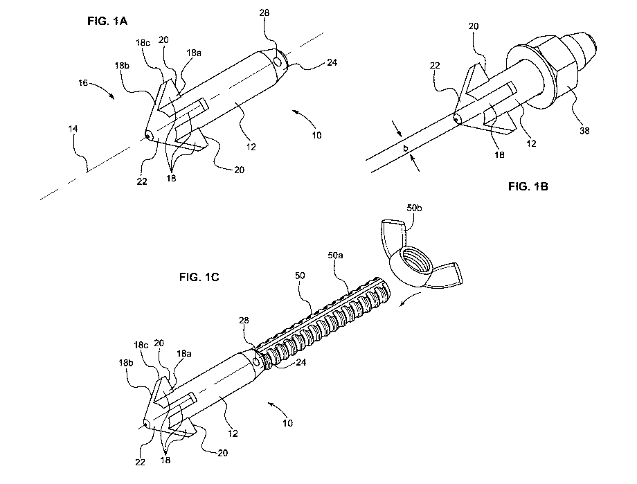
[0056] Fig. lA is a perspective view of a multi-head bolt according to
one or
more aspects of the disclosure;
[0057] Fig. 1B is a perspective view of the multi-head bolt of Fig. 1B
engaged
1() with a nut according to one or more aspects of the disclosure;
[0058] Fig. 1C is a perspective view of the multi-head bolt of Fig. lA
engaged
with an extension shank according to one or more aspects of the disclosure;
[0059] Fig. 2A is a perspective view of a multi-head bolt engaged with
a
plurality of panels according to one or more aspects of the disclosure;
[0060] Fig. 2B is a perspective view of a multi-head bolt engaged with a
panel
having recesses according to one or more aspects of the disclosure
[0061] Figs. 3A-D depicts various stages of connecting a plurality of
panels
with a multi-head bolt according to one or more aspects of the disclosure;
[0062] Figs. 4A-E depicts examples of multi-head bolt geometries
according
to one or more aspects of the disclosure;
[0063] Fig. 5A is a perspective view a multi-head bolt according to
one or
more aspects of the disclosure;
[0064] Fig. 5B is a side view a multi-head bolt according to one or
more
aspects of the disclosure; and
[0065] Fig. 5C is a rear view a multi-head bolt according to one or more
aspects of the disclosure.
DETAILED DESCRIPTION
[0066] Fig. lA is a perspective view of a multi-head bolt 10 according
to one
or more aspects of the disclosure and Fig. 1B is a perspective view of the
multi-head
bolt 10 of Fig. lA engaged with a nut 38 according to one or more aspects of
the
disclosure.
[0067] As shown in Fig. 1A, the multi-head bolt 10 (also referred to
as bolt
10) has a longitudinal shaft 12 having a multi-head 16 at one end thereof At
least a
portion of the longitudinal shaft 12 can be cylindrical or substantially
cylindrical and
CA 03190627 2023-02-01
WO 2022/029743
PCT/IB2021/057337
7
can define a diameter. The longitudinal shaft 12 can include external
threading for
engaging with a nut, as described in detail below. In one example, the
longitudinal
shaft 12 can define a longitudinal axis 14 that is co-axial or substantially
co-axial
relative to the longitudinal shaft and the longitudinal shaft can define an
outer
circumference.
[0068] The multi-head 16 has a plurality of pawls 18 that extend
radially from
the longitudinal axis 14 defined by the longitudinal shaft 12. In the example
of Fig.
1A, the multi-head16 of the bolt 10 includes four pawls 18 that are arranged
radially
and symmetrically with respect to longitudinal axis 14 and can be arranged in
a
symmetrical star-shaped configuration around an outer circumference of the
shaft 12.
In other examples, the bolt 10 can include greater or fewer pawls 18 and can
be
arranged radially, symmetrically and/or arbitrarily with respect to
longitudinal axis
14. For example, the multi-head 16 can include at least or exactly three pawls
18 that
can be arranged arbitrarily or radially and symmetrically with respect to
longitudinal
axis 14. In another example, the multi-head 16 can include at least or exactly
five
pawls 18 that can be arranged arbitrarily or radially and symmetrically with
respect to
longitudinal axis 14.
[0069] Each of the pawls 18 can be unitarily and rigidly formed with
respect
to the longitudinal shaft 12 of the bolt 10 such that each of the pawls 18 has
a fixed
radial orientation with respect to the longitudinal axis. In this regard, the
pawls 18 can
be inelastic and immovable relative to the longitudinal shaft 12 of the bolt
10. The
pawls 18 can be generally fin-shaped and can be defined by a support surface
20,
lateral sides 18a, and angled side 18b. The lateral sides 18a of each
respective pawl 18
can be parallel to one another and can be parallel to a plane extending
radially with
respect to longitudinal axis 14. The lateral sides 18a can extend between the
support
surface 20, the angled side 18b, and the longitudinal shaft 12. The support
surface 20
can be perpendicular to the lateral sides 18a and can extend along a plane
that is
perpendicular to the longitudinal axis 14.
[0070] The angled side 18b can extend from a cone-shaped portion 22 to
the
support surface 20. In some examples, the angled side 18b can extend as a
continuous
surface from the cone-shaped portion 22 to the support surface 20, while in
other
examples there can be a flat portion 18c between the angled side 18b and
support
surface 20. The angled side 18b can be coplanar with a cone-shaped portion 22
and
can form a continuous, uninterrupted surface with the cone-shaped portion 22
and a
CA 03190627 2023-02-01
WO 2022/029743
PCT/IB2021/057337
8
plane coinciding with the angled side 18b can form an angle with the
longitudinal axis
14. In one example, the angle can be an acute angle between 5 and 50 degrees
and in
another example, the angle can be about 45 degrees. While a cone-shaped
portion 22
is depicted, it is contemplated that the portion 22 can be a truncated cone
shape in
other examples.
[0071] The lateral sides 18a can be parallel to each other and can
both be
parallel with a plane extending radially with respect to the longitudinal axis
14. In this
regard, the lateral sides can be perpendicular to the support surface 20. By
virtue of
the configuration, a radial distance of angled side 18b relative to shaft 12
linearly
to decreases as measured from support surface 20 toward cone-shaped portion
22.
[0072] At an opposing end of the longitudinal shaft 12 relative to the
cone-
shaped portion 22 is a cone end 24 that defines a hole 28 therethrough. The
hole 28
allows the bolt 10 to be secured by a safety split pin to one or more formwork
panels
or formwork elements. The cone end 24 facilitates the threading of nut 38 onto
the
longitudinal shaft.
[0073] As shown in Fig. 1B, the bolt 10 can be engaged with the nut 38
to
facilitate engagement with formwork elements (for example one or more beams)
and/or formwork panels and/or any pair of elements that can connected, as will
be
described in greater detail below. The nut 38 can have a female thread and can
have
wings to enable hand-tightening.
[0074] A width of the pawls 18, e.g., a distance between opposing
lateral sides
18a, is depicted as a width b in Fig. 1B. The width can be measured at any
portion of
the pawl, and in one example the width can be measured at or near the support
surface
20. In one example, the width of pawls 18 is less than a diameter of the shaft
12. In
one particular example, the width can be at least 15% of the shaft diameter
and at
most 65% of the diameter of the shaft. In another example, the width can be in
the
range of 25% to 40% of the shaft diameter. In yet another example, the width b
is
approximately 33% of a diameter of the longitudinal shaft 12. In these
examples, the
diameter of the shaft 12 is measured at a middle portion of the shaft, e.g., a
portion
that is disposed between the panels 32 when secured thereto. In one example, a
width
of the pawl can be substantially constant along the longitudinal axis. A width
of the
pawl influences the load bearing capacity of the bolt in such a way that, the
greater
the width the greater the load-bearing capacity with respect to higher tensile
force.
The width also influences load-bearing capacity with respect to transverse
force in an
CA 03190627 2023-02-01
WO 2022/029743
PCT/IB2021/057337
9
inverse manner, e.g. increasing width reduces load-bearing capacity with
respect to
transverse force. Above a certain width, almost no additional traverse force
can be
absorbed.
[0075] In one example, an extension shank 50 is disposed at the end of
the
shaft opposing the multi-head 16. By way of the extension shank 50, the shaft
can be
equipped with a tension rod. In another example, the end part of the shaft 12
the
multi-head bolt 10 can be equipped with a tension rod. The shank 50 can have
an
external thread 50a on which a nut 50b can be screwed or the shank 50 can be
in the
form of an anchor that is to be fixed in the concrete. Such shank 50 is
commercially
available from DYWIDAGO known under the corresponding trademark
DYWIDAGO-extension.
[0076] Each of the pawls 18 can define a primary plane associated
therewith,
the primary plane being defined as parallel to each of the lateral sides 18a
and
extending through the pawl 18 such that the longitudinal axis 14 lies on the
primary
plane. In the example of a four-pawl configuration, the primary plane of a
pawl and
its opposing pawl are co-planar. In this regard, the primary plane of the pawl
18 can
be defined intersecting with the support surface 20 and angled edge 18b such
that the
longitudinal axis 14 lies upon the primary plane.
[0077] Fig. 2A is a perspective view of a multi-head bolt 10 engaged
with a
plurality of plates 32 according to one or more aspects of the disclosure and
Fig. 2B is
a perspective view of plate 32 having recesses according to one or more
aspects of the
disclosure.
[0078] Each of the plates 32 can engage with formwork panels or
formwork
elements, or in another example can be integrally formed with the formwork
panel or
formwork element, for example by welding or the like. Each of the plates 32
(e.g., a
frame of the plate 32) define respective an opening 32a for receiving the bolt
10, with
the opening 32a corresponding to an outer diameter of the longitudinal shaft
12. The
opening 32a of the plates 32 can define cut-outs 34 shaped to receive the
pawls 18 and
to allow the pawls 18 to pass through the opening 32a. In this regard, the cut-
outs 34
are positioned to correspond to radial positions of the pawls 18 and the
number of cut-
outs 34 corresponds to the number of pawls 18. For example, in the example of
three
pawls 18, the panel 32 defines three cut-outs 34.
[0079] The plates 32 can also define recesses 36 (e.g., anti-twist
structures)
that are circumferentially adjacent to the cut-outs 34. In this regard, the
recesses 36
CA 03190627 2023-02-01
WO 2022/029743
PCT/IB2021/057337
do not extend an entire thickness of the plates 32 and have a thickness that
is less than
the overall thickness of the plate 32. This thickness arrangement creates a
space to
receive the pawls 18, and in one example, the support surfaces 20, to ensure a
locking
arrangement, which will be explained in greater detail below. In one example,
the
5 recesses 36 can define chamfered edges to provide easier movement and
insertion of
the pawls 18 relative to the opening 32a and recesses 36. In one example, the
recesses
36 can define a stepped design along a thickness direction of the plate 32
corresponding to a shape of the pawls 16. The plates 32 can also include
stoppers 30
(e.g., twist-stop(s)) protruding from a surface of the plate 32 and extending
above a
10 surface of the plates 32 arranged circumferentially adjacent to the
recesses 36 to
prevent rotation of the bolt 10 and pawls 18 beyond a locking position and to
prevent
the respective pawls 18 from aligning with a cut-out 34 different from the cut-
out
through which it was advanced. In this regard, rotation of the pawls 18 and
the multi-
head can be prevent or limited when a lateral side 18a (e.g., an abutting
surface or any
other surface of the pawl) abuts against an abutting surface of the stopper
30. The
number of stoppers 30 (e.g., twist-stop(s)) can be less than or at least equal
to the
number of pawls.
[0080] This provides a stable configuration for diverting a shear
force and/or
tension force from the bolt 10 to the plate 32. In the example of a star-like
arrangement of the at least three pawls around the bolt shaft, any shear force
is
diverted in the plane of the panel irrespective from which direction it is
caused. This
provides a positive high clamp load and, in particular by virtue of the at
least three
pawls a high capability to absorb sheer loads and/or tensions loads aiding
therewith to
divert any shear force and/or tension force into those objects as fastened by
the
system, e.g., onto the panel's surface
[0081] Figs. 3A-D depict various stages of connecting a plurality of
plates 32
with a multi-head bolt 10 according to one or more aspects of the disclosure.
[0082] As shown in Fig. 3A, the bolt 10 is inserted into both of the
respective
openings 32a defined by the plates 32. In this regard, each of the pawls 18 of
the
multi-head 16 are aligned with the corresponding cut-outs 34 of the plates 32,
allowing the pawls 18 and the bolt 10 to pass through the openings 32a.
[0083] By virtue of the relationship between cone-shaped portion 22
and
angled edge 18b, the bolt 10 can be easily inserted through the openings 32a
of the
plates 32. Further, if the plates 32 are slightly out of alignment, the bolt
10 and the
CA 03190627 2023-02-01
WO 2022/029743
PCT/IB2021/057337
11
cone-shaped portion 22 and pawls 18 provide a centering function between the
plates
32. For example, if the plates 32 are slightly out of alignment, pushing the
bolt 10
with truncated cone 22 will automatically orient the plates 32 such that the
openings
32a are aligned since the bolt 10 can only pass through the openings 32a and
the
pawls 18 can only pass through the cut-outs 34 when they are in alignment.
[0084] As shown in Fig. 3B, the bolt 10 has been inserted into both
plates 32
and will be rotated according to the directional arrow. The pawls 18 having
previously
been aligned with cut-outs 34 will rotate out of position with cut-outs 34 and
the
support surfaces 20 of the pawls will engage with a face of the plate 32 (or
within
recesses 36, for example by retracting the bolt in a direction opposite of the
insertion
direction and allowing the pawls to rest and engage within the space defined
by the
recesses and preventing further rotation).
[0085] As shown in Fig. 3C, the bolt has been rotated (e.g., by 45
degrees or a
geometric multiple) and the pawls 18 are 45 degrees out of alignment with the
cut-
outs 34, thereby preventing the bolt 10 from being removed from the plates 32
without additional rotation. In one example, the rotation of the pawls can be
ceased or
limited by one or more stoppers 30.
[0086] As shown in Fig. 3D, the plates 32 are aligned and engaged with
one
another by virtue of the bolt 10. A nut 38 (and optional washer) can be
threaded onto
the bolt 10 to secure the plates 32 relative to one another.
[0087] Figs. 4A-E depict examples of multi-head bolt geometries
according to
one or more aspects of the disclosure. As shown, the multi-head of the bolt
can be a
triangle, a three-pawl, four-pawl, or five-pawl arrangement. Various multi-
head
configurations are their corresponding openings and cut-outs in an exemplary
plate
are depicted in Fig. 4A.
[0088] Fig. 4B depicts a five-pawl configuration in which five pawls
are
arranged symmetrically with respect to bolt shaft. In this regard, there is
approximately 72 degrees between each of the pawls. With this multi-head, the
plate
can be configured with an opening that defines five cut-outs, five recesses,
and five
stoppers.
[0089] Fig. 4C depicts a four-pawl configuration in which four pawls
are
arranged symmetrically with respect to bolt shaft. In this regard, there is
approximately 90 degrees between each of the pawls. With this multi-head, the
plate
can be configured with an opening that defines four cut-outs, four recesses,
and four
CA 03190627 2023-02-01
WO 2022/029743
PCT/IB2021/057337
12
stoppers. In this example, each of the pawls can be diametrically opposed to a
respective pawl. In this regard, each pawl can have an oppositely oriented
pawl
disposed 180 degrees therefrom.
[0090] Since the design of pawls as extending from the shaft simultaneously
define
and dictate the negative profile in an opening of the plate to push the bolt
through,
meaning the cut-outs for the pawls that extend from the cut-out for the
circumference
of the shaft, in one example the number of pawls is advantageously four. This
allows
for a configuration that each pawl namely decreases the support area on the
surface of
the plate on which the pawl can rest on after fastening the bolt ¨ which is
also
1() dependent from the width of a pawl.
[0091] Fig. 4D depicts a three -pawl configuration in which three
pawls are
arranged symmetrically with respect to bolt shaft. In this regard, there is
approximately 120 degrees between each of the pawls. With this multi-head, the
plate
can be configured with an opening that defines three cut-outs, three recesses,
and
three stoppers. Such a three-pawl configuration provides a well-balanced force
distribution in the horizontal plane on the panel's surface in any direction
around
360 .
[0092] Fig. 4E depicts a multi-head having a triangular cross-section,
with
each corner defining a pawl and thus a three-pawl configuration. With this
multi-head,
the plate can be configured with an opening that defines three cut-outs, three
recesses,
and three stoppers.
[0093] Fig. 5A is a perspective view a multi-head bolt 500 according
to one or
more aspects of the disclosure. Fig. 5B is a side view a multi-head bolt 500
according
to one or more aspects of the disclosure. Fig. 5C is a rear view a multi-head
bolt 500
according to one or more aspects of the disclosure.
[0094] As shown in Fig. 5A, the multi-head bolt 500 (also referred to
as bolt
500) has a longitudinal shaft 512 having a multi-head 516 at one end thereof
At least
a portion of the longitudinal shaft 512 can be cylindrical or substantially
cylindrical
and can define a diameter. The longitudinal shaft 512 can include external
threading
526 for engaging with a nut, as described in detail above. In one example, the
longitudinal shaft 512 can define a longitudinal axis 514 that is co-axial or
substantially co-axial relative to the longitudinal shaft and the longitudinal
shaft can
define an outer circumference.
CA 03190627 2023-02-01
WO 2022/029743
PCT/IB2021/057337
13
[0095] The multi-head 516 has a plurality of pawls 18 that extend
radially
from the longitudinal axis 514 defined by the longitudinal shaft 512. In the
example
of Fig. 5A, the multi-head 516 of the bolt 510 includes four pawls 518 that
are
arranged radially and symmetrically with respect to longitudinal axis 514 and
can be
arranged in a symmetrical star-shaped configuration around an outer
circumference of
the shaft 512. In other examples, the bolt 510 can include greater or fewer
pawls 518
and can be arranged radially, symmetrically and/or arbitrarily with respect to
longitudinal axis 514. For example, the multi-head 516 can include at least or
exactly
three pawls 518 that can be arranged arbitrarily or radially and symmetrically
with
respect to longitudinal axis 514. In another example, the multi-head 516 can
include
at least or exactly five pawls 518 that can be arranged arbitrarily or
radially and
symmetrically with respect to longitudinal axis 14.
[0096] Each of the pawls 518 can be unitarily and rigidly formed with
respect
to the longitudinal shaft 512 of the bolt 510 such that each of the pawls 518
has a
fixed radial orientation with respect to the longitudinal axis. In this
regard, the pawls
518 can be inelastic and immovable relative to the longitudinal shaft 512 of
the bolt
510. The pawls 518 can be generally fin-shaped and can be defined by a support
surface 520, lateral sides 518a, and angled side 518b. The lateral sides 518a
of each
respective pawl 518 can be symmetrically opposed to one another and form an
acute
angle relative to a plane extending radially with respect to longitudinal axis
514. The
lateral sides 518a can extend between the support surface 520, the angled side
518b,
and the longitudinal shaft 512. A transition between longitudinal shaft 512
and
support surface 520 can be a right angle or can be rounded due to
manufacturing
tolerances. In some examples, the rounded transition can be rounded in such a
manner
that the rounding can be felt upon handling but may not visible to the eye. A
transition
between longitudinal shaft 512 and lateral sides 518a can be angled or can be
rounded
due to manufacturing tolerances. In some examples, the rounded transition can
be
rounded in such a manner that the rounding can be felt upon handling but may
not
visible to the eye. A transition between support surface 520 and flat portion
518c can
be a right angle or can be rounded due to manufacturing tolerances. In some
examples, the rounded transition can be rounded in such a manner that the
rounding
can be felt upon handling but may not visible to the eye. A transition between
flat
surface 518c and angled side 518b can be an angled or can be rounded due to
manufacturing tolerances. In some examples, the rounded transition can be
rounded in
CA 03190627 2023-02-01
WO 2022/029743
PCT/IB2021/057337
14
such a manner that the rounding can be felt upon handling but may not visible
to the
eye. The support surface 520 can extend radially with respect to the
longitudinal axis
514 and the longitudinal shaft 512 and can extend along a plane that is
perpendicular
to the longitudinal axis 514.
[0097] The angled side 518b can extend from a cone-shaped portion 522 to
the support surface 20. In some examples, the angled side 518b can extend as a
continuous surface from the cone-shaped portion 522 to the support surface
520,
while in other examples there can be a flat portion 518c between the angled
side 518b
and support surface 520. The angled side 518b can be coplanar with a cone-
shaped
portion 522 and can form a continuous, uninterrupted surface with the cone-
shaped
portion 522 and a plane coinciding with the angled side 518b can form an angle
with
the longitudinal axis 514. In one example, the angle can be an acute angle
between 5
and 50 degrees and in another example, the angle can be about 45 degrees. Cone-
shaped portion 522 can include a substantially flat portion 522a, such that
cone-
shaped portion 522 is a truncated cone shape with the flat portion 522a being
perpendicular the longitudinal axis 514.
[0098] At an opposing end of the longitudinal shaft 512 relative to
the cone-
shaped portion 522 is a threaded portion 526 that defines a hole 528
therethrough and
a hexagonal attachment portion 524 that defines a plurality of slots 524a. The
hole
528 allows the bolt 510 to be secured by a safety split pin to one or more
formwork
panels or formwork elements. The cone end 524 facilitates the threading of nut
(e.g.,
nut 38 described above) onto the longitudinal shaft.
[0099] The bolt 500 can be engaged with a nut (e.g. nut 38) to
facilitate
engagement with formwork elements (for example one or more beams) and/or
formwork panels and/or any pair of elements that can connected, as will be
described
in greater detail below. The nut can have a female thread and can have wings
to
enable hand-tightening.
[00100] While the example of Figs. 1A-1C, the lateral sides 18a are
parallel, as
shown in Fig. 5B, the lateral sides 518a are not parallel with one another and
are
arranged at an acute angle relative to the longitudinal axis and the primary
plane. This
is depicted in Fig. 5B and 5C, with lateral sides 518a defining a plane AE
that forms
an acute angle relative to the primary plane PP, with the longitudinal axis
514 lying
on the primary plane PP (with the primary plane PP bisecting the pawl 518 and
the
lateral sides 518a being symmetric relative to the primary plane PP). As
depicted in
CA 03190627 2023-02-01
WO 2022/029743
PCT/IB2021/057337
Fig. 5B and 5C, the lateral sides 518a extend outwardly from the longitudinal
shaft
512 and define two tapers: 1) the lateral sides 518a are tapered or slightly
tapered
toward each other from the longitudinal shaft 514 toward the angled side 518b
relative to the primary plane PP when viewed from the hexagonal attachment
portion
5 524 in Fig. 5C, resulting in an acute angle between PP and AE as viewed
from the
hexagonal attachment portion 524, and 2), opposing lateral sides 518a taper
toward
each other from the support surface 520 toward the cone-shaped portion 522
when
viewed from the side in Fig. 5B, resulting in a narrowing/decrease in width of
the
angled side 518b from the support surface 520 toward the cone-shaped portion
522. In
10 this regard, a width of the pawls 518 can decrease as measured from the
support
surface 520 toward the cone-shaped portion 522. In some examples, the acute
angle
for each lateral side 518a between AE and PP can be approximately 5 degrees or
less.
In one example, the acute angle for each lateral side 518a between AE and PP
can be
approximately 3 degrees. In some examples, the cone-shaped portion 522 is
shaped as
15 a truncated cone, with a substantially flat portion 522a.
[00101] As described above, a width of the pawls 518, e.g., a distance
between
opposing lateral sides 518a, can decrease as measured from the support surface
520
toward the cone-shaped portion 522 by virtue of the acute angle relationship
of the
lateral sides 518a relative to the longitudinal axis.
[00102] In one example, the width of pawls 518 is less than a diameter of
the
shaft 512. In one particular example, the width can be at least 15% of the
shaft
diameter and at most 65% of the diameter of the shaft. In another example, the
width
can be in the range of 25% to 40% of the shaft diameter. In yet another
example, the
width b is approximately 33% of a diameter of the longitudinal shaft 512. In
these
examples, the diameter of the shaft 512 is measured at a middle portion of the
shaft,
e.g., a portion that is disposed between the panels 32 when secured thereto,
and the
width of the pawls 518 is measured at a portion near the support surface 520
(e.g.,
where the width of the pawl 518 is greatest, by virtue of the acute angle
orientation of
lateral sides 518a).
[00103] As described above, a width of the pawl influences the load bearing
capacity of the bolt in such a way that, the greater the width the greater the
load-
bearing capacity with respect to higher tensile force. The width also
influences load-
bearing capacity with respect to transverse force in an inverse manner, e.g.
increasing
CA 03190627 2023-02-01
WO 2022/029743
PCT/IB2021/057337
16
width reduces load-bearing capacity with respect to transverse force. Above a
certain
width, almost no additional traverse force can be absorbed.
[00104] Each of the pawls 518 can define a primary plane associated
therewith,
the primary plane being defined as a plane that symmetrically bisects each
pawl 518,
and intersects both the support surface 520 and angled edge 518b of the pawl
such
that the longitudinal axis 514 lies on the primary plane. In the example where
the
lateral sides 518a are not parallel, the lateral sides 518a would be oriented
at the same
acute angle relative to the primary plane as they are to the longitudinal axis
514.
[00105] As shown in Fig. 5C, a rear end 524 defines a hexagonal
attachment
portion that is configured to be engaged with a tool, such as an open end
wrench, for
efficient rotation of the bolt 500. The rear end 524 can also define one or
more slots
524a that generally define a "+" (e.g., plus sign) configuration. As shown,
the slots of
the + configuration align with the pawls 518 such that the primary plane of
each pawl
518 would intersect with its respectively aligned slot 524a. During insertion
of the
bolt 500 through an opening and/or corresponding cutouts (e.g., of plate 32,
or any
other type of formwork elements (for example one or more beams) and/or
formwork
panels and/or any pair of elements that can connected), the slots 524a can
provide
visual alignment to the worker installing the bolt 500 such that, upon
rotation of the
bolt 500 to engage with the element (as depicted in Figs. 2A-B and 3A-D
above),
angular rotation of the pawls 518 results in corresponding angular rotation of
the slots
524a, providing the worker with visual guidance regarding engagement of the
bolt
500 with the element.
[00106] The foregoing has been a detailed description of illustrative
embodiments of the invention. Various modifications and additions can be made
without departing from the spirit and scope of this invention. Features of
each of the
various embodiments described above may be combined with features of other
described embodiments as appropriate in order to provide a multiplicity of
feature
combinations in associated new embodiments. Furthermore, while the foregoing
describes a number of separate embodiments of the apparatus and method of the
present invention, what has been described herein is merely illustrative of
the
application of the principles of the present invention. Accordingly, this
description is
meant to be taken only by way of example, and not to otherwise limit the scope
of this
invention.
[00107] What is claimed is: