Note: Descriptions are shown in the official language in which they were submitted.
WO 2022/051178
PCT/US2021/047879
UNIVERSAL HANDPIECE FOR ELECTRICAL TREATMENT
APPLICATOR
CROSS REFERENCE TO RELATED APPLICATIONS
[0001] This patent application claims priority to U.S. provisional
patent application no.
63/073,907, filed on 09/02/2020, titled "UNIVERSAL HANDPIECE FOR ELECTRICAL
TREATMENT APPLICATOR" and herein incorporated by reference in its entirety.
INCORPORATION BY REFERENCE
[0002] All publications and patent applications mentioned in this
specification are herein
incorporated by reference in their entirety to the same extent as if each
individual publication or
patent application was specifically and individually indicated to be
incorporated by reference.
FIELD
[0003] Described herein are electrical treatment applicators,
including handles that allow
connection to a variety of removable electrode tips with selectable impedance
matching.
Specifically, described herein are handles/handpieces that select impedance
matching based on
an encoding shape engagement with a removable electrode tip, for high-voltage
electrical
therapy.
BACKGROUND
[0004] When applying rapid pulsing, poor impedance matching may
lead to reflections and
distortions in the applied electrical pulses. This problem may be particular
acute when applying
short (e.g., sub-microsecond) pulses at very high field strength, as have been
described for
electromanipulation of biological cells. For example, electric pulses may be
used in treatment of
human cells and tissue including tumor cells, such as basal cell carcinoma,
squamous cell
carcinoma, and melanoma. The voltage induced across a cell membrane may depend
on the pulse
length and pulse amplitude. Pulses shorter than about 1 microsecond may affect
the cell interior
without adversely or permanently affecting the outer cell membrane, and result
in a delayed cell
death with intact cell membranes. Such shorter pulses with a field strength
varying in the range
of several kV/cm to 100 kV/cm may trigger apoptosis (i.e. programmed cell
death) in some or all
of the cells exposed to the described field strength and pulse duration. These
higher electric field
strengths and shorter electric pulses may be useful in manipulating
intracellular structures, such
as nuclei and mitochondria.
- 1 -
CA 03190840 2023- 2- 24
WO 2022/051178
PCT/US2021/047879
[0005] Nanosecond high voltage pulse generators have been proposed
for biological and
medical applications. For example, see: Gundersen et al. "Nanosecond Pulse
Generator Using a
Fast Recovery Diode", IEEE 26th Power Modulator Conference, 2004, pages 603-
606; Tang et
al. "Solid-State High Voltage Nanosecond Pulse Generator," IEEE Pulsed Power
Conference,
2005, pages 1199-1202; Yampolsky et al.. "Repetitive Power Pulse Generator
With Fast Rising
Pulse", U.S. Pat. No. 6,831,377; Schoenbach et al. "Method and Apparatus for
Intracellular
Electro-Manipulation", U.S. Pat. No. 6,326,177; Kuthi et al., "High Voltage
Nanosecond Pulse
Generator Using Fast Recovery Diodes for Cell Electro-Manipulation", U.S. Pat.
No. 7,767,433;
Krishnaswamy et al., "Compact Subnanosecond High Voltage Pulse Generation
System for Cell
Electro-Manipulation", U.S. Patent Application No. 2008/0231337; and Xiao et
al. "High-
Voltage Analog Circuit Pulser with Feedback Control", US Patent 10,548,665 B2
. The entire
content of these publications is incorporated herein by reference.
[0006] Such pulse generators are used with various treatment
applicators containing a set of
electrodes. In some cases, an applicator may be configured to operate with
multiple different
types of electrodes (e.g., applicator tips) for use with a variety of
different tissues or tissue
geometries and/or therapies. However, the physical size of circuit components
needed at the high
voltages and currents make it difficult to provide an acceptable applicator
configuration that can
be used with a variety of differently configured removable/swappable electrode
tips. It is
desirable to provide improved treatment applicator configurations that will
allow for impedance
matching to reduce reflections and distortions in the applied electrical
pulses and allow to use a
variety of removable/swappable electrode tips with the same treatment
applicator.
[0007] The methods and apparatuses described and illustrated herein
may address the issues
discussed above.
SUMMARY OF THE DISCLOSURE
[0008] Described herein are methods and apparatuses (e.g., devices
and systems, including
handles or handpiece for electric treatment applicators) for the automatically
and/or
mechanically (including electro-mechanically) selecting and applying impedance
matching for a
variety of differently configured treatment tips (electrode tips). Impedance
matching of applied
electrical energy, particularly energy applied to a biological tissue to be
treated, may minimize
reflections and may improve the power transferred. These methods and
apparatuses may be
useful for applying therapeutic energy, including but not limited to short,
high field strength
electric pulses, while avoiding the risk of arcing or otherwise harming the
tissue. Further, these
apparatuses and methods may be well suited, for example, for any treatments
involving sub-
- 2 -
CA 03190840 2023- 2- 24
WO 2022/051178
PCT/US2021/047879
microsecond (e.g., nanosecond, picosecond, etc.) pulsing, such as but not
limited to the treatment
of various diseases, skin disorders, and abnormal tissue growth.
[0009] In particular, the apparatuses and methods described herein
may be configured for use
with a plurality of differently configured treatment tips (e.g., single-use
treatment tips or
reusable), as will be described in greater detail herein.
[0010] The apparatuses described herein may be used with a pulse
generator and may be
provided as a part of the pulse generator systems. In particular, these
apparatuses may include an
applicator comprising a handle (also referred to as a handpiece or an
applicator handle) that is
configured to removably couple with a variety of different treatment tips
(e.g., electrode tips), so
that the applicator may deliver energy generated by the pulse generator
through a treatment tip
into the tissue. For clarity and avoidance of any doubt, the term "handle",
"applicator handle" or
"handpiece", as used herein, refers to any structure to support, hold or
attach to the electrode
portion (treatment tip portion) of the device, whether it is intended to be
hand-held, or attached
to the robotic arm, or for percutaneous or other minimally invasive
applications and for catheter-
based delivery. In some examples the handle may include a manual grip, in some
examples it
may be configured to be held by a robotic manipulator (e.g., arm, etc.), or it
may be configured
for introduction through the scope or a catheter. Typically, these apparatuses
(e.g., device,
instruments and systems, including handles) may engage with an electrode tip
so that coupling
and engaging the electrode tip with the handle automatically couples an
appropriate impedance
matching circuit within the handle to the electrodes of the electrode tip, so
that the electrical
energy applied to the electrode tip is modified by the selected impedance
matched circuit.
[0011] In some examples, these handles, which may also be referred
to as applicator handles,
may include an interface for removably engaging the electrode tip, and a
plurality of different
impedance matching circuits. These impedance matching circuits may include one
or more
resistors and may be configured in the circuit in parallel to the electrodes
of the electrode tip and
the pulse generator. An impedance matching circuit may include one or more
combinations of
the impedance matching element; different impedance matching circuits may
share impedance
matching elements (e.g., resistors, inductors, capacitors, etc.). Thus,
different impedance
matching circuits may share components that may be combined in differently to
create different
impedance matching circuits by forming different combinations of overlapping
components. The
handle may also include an impedance matching selector that is part of the
interface between the
handle and the treatment tip. The impedance matching selector may receive the
encoding shape
connector or encoding shape connection from the electrode tip and may couple
or configure the
appropriate one or more impedance matching circuits in the handle to the
electrode tip based on
the encoding shape connection.
- 3 -
CA 03190840 2023- 2- 24
WO 2022/051178
PCT/US2021/047879
[0012] For example, described herein are handles for treatment
applicators that may be used
with a variety of different electrode tips, and may automatically, and/or
mechanically and/or
electro-mechanically, adjust the impedance matching, for example, by selecting
a particular
impedance matching circuit (e.g., in some examples a combination of shared
circuit components)
associated with a particular tip configured for coupling with the handle of
the applicator. A
handle as described herein may include: a plurality of impedance matching
circuits; a plurality of
handle connectors (e.g., electrical or electro-mechanical) configured to
engage with a plurality of
electrode tip connectors (e.g., electrical or electro-mechanical) on an
electrode tip so that a
plurality of electrodes of the electrode tip are in electrical communication
with the pulse
generator; and an impedance matching selector configured to selectively couple
the plurality of
electrode tip connectors with one or more of the impedance matching circuits
of the plurality of
impedance matching circuits based on an encoding shape connection with the
electrode tip.
[0013] The impedance matching selector may be configured to receive
the encoding shape
connection from the treatment tip (electrode tip) in order to connect one or
more of the
impedance matching circuits within the handle to the electrode tip.
[0014] The encoding shape connection (also referred to herein as a
keyed connector, or an
encoding shape connector) may be one or more: projection, protrusion, cavity,
pin, bar, bump,
ridge, etc. In general, as used herein an encoding shape connection refers to
a shape,
configuration or orientation that corresponds to an impedance setting on the
handle. The
encoding shape connection may specifically identify a particular impedance
setting when
engaged when the tip engages with the handle via the mechanical connection
between the tip and
the handle. In some examples the encoding shape connection may be a protrusion
extending
from the electrode tip into the handle (e.g., into the impedance matching
selector. In some
examples the encoding shape connection comprises a plurality of pins. The
encoding shape
connection may be all or part of the electrical connector(s) of the electrode
tip that arc in
electrical communication with the one or more electrodes on the electrode tip.
For example, in
some examples the encoding shape connection may be formed, as least in part,
by the plurality of
electrode tip connectors on the treatment tip. In one example, the encoding
shape connection of
the electrode tip includes a plurality of pins extending from the electrode
tip that are conductive
and also form the electrode tip electrical connector(s).
[0015] The plurality of impedance matching circuits may be housed
within the handle. For
example, a handle housing may enclose all or part of the plurality of
impedance matching
circuits. The plurality of impedance matching circuits may each include a pair
of connectors,
referred to herein as internal connectors, that may form a part of the
impedance matching
selector and may selectively couple each impedance matching circuit to the
electrode tip
- 4 -
CA 03190840 2023- 2- 24
WO 2022/051178
PCT/US2021/047879
electrical connectors in order to provide impedance matching. For example, the
plurality of
impedance matching circuits may be arranged so that the impedance matching
circuits may each
be connected in parallel with one another.
[0016] At least one of the plurality of impedance matching circuits
may comprise a resistor
configured to be arranged in a circuit in parallel between two or more of the
plurality of
electrode tip electrical conductors. In some examples these resistors may be
between 10 and 800
Ohms (e.g., between 100 and 500 Ohms, between 10 and 500 Ohms, between 100 and
400
Ohms, between 100 and 800 Ohms, between 150 and 350 Ohms, between 200 and 800
Ohms,
etc.). Multiple resistors may be used.
[0017] The impedance matching selector may include a plurality of internal
connectors that
may be static (e.g., in a fixed position relative to each other) or all or
some of them may be
movable. For example, the impedance matching selector may include a plunger
configured to be
displaced by the encoding shape connection with the electrode tip. Displacing
the plunger may
move one or more internal connectors (e.g., one or more pairs of internal
connectors) into contact
with another internal connector to place one or more of the plurality of
impedance matching
circuits in electrical contact (and in some cases, in parallel with) the
connection between the
electrical connectors of the electrode tip and the pulse generator.
[0018] Any of the apparatuses and methods described herein may be
configured so that, even
when operating to generate a sub-microsecond, high-voltage pulsed electrical
field (e.g., equal or
greater than 1 kilovolts per centimeter (kV/cm), 5 kV/cm, 10 kV/cm, 20 kV/cm,
50 kV/cm, 100
kV/cm, 150 kV/cm, 300 kV/cm, 500 kV/cm, etc.), arcing within the handle is
prevented between
the internal electrical connectors coupled to the plurality of impedance
matching circuits. For
example, in some examples the impedance matching selector comprises a first
set of internal
electrical contacts that are separated from a second set of internal
electrical contacts by an air
gap, and wherein the first set of electrical contacts is in electrical
communication with the pulse
generator forming a first impedance matching circuit of the plurality of
impedance matching
circuits and the second set of internal electrical contacts is in electrical
communication with a
second impedance matching circuit of the plurality of impedance matching
circuits. In any of
these examples the internal electrical contacts of the first set of internal
electrical contacts may
be separated from each other by a minimum clearance distance. The minimum
clearance distance
may be the distance that is greater than a shortest distance or path that
prevents an arc between
two conductive parts measured along any surface of combination of surfaces of
an insulting
material, and/or a shortest path in the air between two conductive parts that
prevents an arc. See,
e.g., W02018053539, herein incorporated by reference in its entirety. For
example, the
minimum clearance distance may be of about 20 mm or greater (e.g., 25 mm or
greater, 30 mm
- 5 -
CA 03190840 2023- 2- 24
WO 2022/051178
PCT/US2021/047879
or greater, 35 mm or greater, 40 mm or greater, 45 mm or greater, 48 mm or
greater, 50 mm or
greater, etc.), e.g., when delivering pulsing at about 15 kV. In examples in
which the delivered
pulses are less than 15 kV, the minimum clearance distance may be
proportionally smaller (e.g.,
mm or greater, 15 mm or greater, etc., where the pulses delivered have a peak
of about 10
5 kV).
[0019] As mentioned, in some examples all or some of the internal
electrical contacts of the
impedance matching selector may be moved when engaging the encoding shape
connection of
the electrode tip to the impedance matching selector. For example, a second
set of electrical
contacts (that coupled to one or more of the impedance matching circuits in
the handle) may be
10 configured to be displaced by impedance matching selector to place the
second impedance
matching circuit in parallel with the first impedance matching circuit based
on the selected
encoding shape connection with the electrode tip.
[0020] As mentioned, the impedance matching selector may include or
be part of the (e.g.,
electrical or electro-mechanical) connector(s) on the handle that engage with
the electrode tip
(e.g., electrical or electro-mechanical) connectors to place the electrodes of
the electrode tip in
communication with the pulse generator. In some examples, the plurality of
handle connectors
may form a part of the impedance matching selector.
[0021] For example, a handle of a treatment (e.g., pulse)
applicator may include: a plurality
of impedance matching circuits; a plurality of handle connectors configured to
engage with a
plurality of electrode tip connectors so that a plurality of electrodes of the
electrode tip are in
electrical communication with the pulse generator through one or more of the
impedance
matching circuits; and an impedance matching selector configured to
selectively couple the
plurality of electrode tip connectors with one or more of the impedance
matching circuits of the
plurality of impedance matching circuits based on an encoding shape connection
with the
electrode tip, wherein the impedance matching selector comprises a first set
of internal electrical
contacts that is separated from a second set of internal electrical contacts
by an air gap, and
wherein the first set of electrical contacts is in electrical communication
with a pulse generator
forming a first impedance matching circuit of the plurality of impedance
matching circuits and
the second set of internal electrical contacts is in electrical communication
with a second
impedance matching circuit of the plurality of impedance matching circuits. In
some examples
all or some of the impedance matching circuits may be on the tip and/or on the
pulse generator
rather than in the handle. In some examples the impedance matching components
(e.g., resistors
or other impedance circuit components) may be in both the handle and the tip
and/or in the pulse
generator.
- 6 -
CA 03190840 2023- 2- 24
WO 2022/051178
PCT/US2021/047879
[0022] These handles may be part of an instrument (e.g., an
applicator) or a system that may
include a pulse generator. Any of these instruments or systems may also or
alternatively include
one or more electrode tips. For example, an applicator may include: a
removable electrode tip,
the electrode tip comprising a plurality of electrodes, and a plurality of
electrode tip connectors
in communication with the plurality of electrodes; and a handle, the handle
comprising a
plurality of impedance matching circuits (which may be configured as dedicated
circuits or may
overlap and share components between difference circuits); a plurality of
handle connectors
configured to engage with the plurality of electrode tip connectors so that
the plurality of
electrodes of the electrode tip are in electrical communication with the pulse
generator; and an
impedance matching selector configured to selectively couple the plurality of
electrode tip
electro-mechanical connectors with one or more of the impedance matching
circuits of the
plurality of impedance matching circuits based on an encoding shape connection
with the
electrode tip.
[0023] The electrode tip may be configured to be removably coupled
to a distal end of the
handle. Any of these applicators or instruments may include additional
electrode tips, such as a
second removable electrode tip having an encoding shape connection that is
different from the
encoding shape connection of the removable electrode tip (e.g., the first
removable electrode tip).
[0024] Also described herein are systems, including systems for
mechanically selecting
impedance matching for an electrode tip when coupling the tip to a handle of a
pulse generator.
For example, a system may include: a pulse generator; a removable electrode
tip, the removable
electrode tip comprising: a plurality of electrodes, and a plurality of
electrode tip electrical
connectors in communication with the plurality of electrodes; a handle, the
handle comprising a
plurality of handle electrical connectors configured to engage with the
plurality of electrode tip
electrical connectors so that the plurality of electrodes of the electrode tip
are in electrical
communication with the pulse generator; a plurality of impedance matching
circuits; and an
impedance matching selector configured to selectively couple the plurality of
electrode tip
electrical connectors with one or more of the impedance matching circuits of
the plurality of
impedance matching circuits based on an encoding shape connection with the
electrode tip.
[0025] In any of the apparatuses (e.g., systems) described herein
the impedance matching
circuits may be located in the handle and/or the tip, and/or the pulse
generator. The impedance
matching circuits may be spread out between the tip, the handle and/or the
pulse generator. In
some examples, as described herein, the impedance matching circuits may be
primarily or
exclusively located in the handle. In some examples the impedance matching
circuits may be
primarily or exclusively located in the pulse generator.
- 7 -
CA 03190840 2023- 2- 24
WO 2022/051178
PCT/US2021/047879
[0026] Alternatively or additionally, in any of the examples
described herein, the impedance
matching circuits may share circuit components (e.g., resistors, capacitors,
inductors, etc.)
between some (or all) of the separate impedance matching circuits described
herein.
[0027] As described above, in general the interface between a tip
and the pulse generator,
e.g., the handle, may determine which impedance matching circuits (and
therefore which
resistors and/or other elements of the impedance matching circuit) may be
connected between
the electrode(s) in the tip and the pulse generator. For example, the tip
configuration, including
tip size, and/or any other shape that may be matched (shape matched) to the
handle may
mechanically (and in some cases electrically) select the impedance matching
circuit, or the
components (e.g., resistors, capacitors, inductors, etc.) forming the
impedance matching circuits.
[0028] As mentioned, the encoding shape connection of the electrode
tip may comprise a
protrusion extending from the electrode tip into the handle. For example, the
encoding shape
connection may comprise a plurality of pins forming the plurality of electrode
tip connectors.
[0029] Also described herein arc methods of using any of these
apparatuses and systems. For
example, described herein are methods of selecting an impedance circuit for a
removable
electrode tip of a pulse applicator that include: removably coupling a first
electrode tip to a
handle of a pulse applicator; and engaging a first encoding shape connector
from the first
electrode tip with an impedance matching selector of the handle, wherein the
impedance
matching connector selectively places a plurality of electrode tip connectors
of the first electrode
tip in electrical communication with one or more impedance matching circuits
within the handle
based at least in part on the first encoding shape connector, so that a pulse
generator may be in
electrical communication with the first electrode tip through the selected one
or more impedance
matching circuits. In some examples the method may include coupling the pulse
generator to the
tip. Alternatively or additionally, the tip may be connected to the handle
(e.g., the handled of a
pulse applicator) before connecting to the pulse generator. Thus, it is not
necessary to couple the
tip to the handle with the pulse generator attached. In general, the methods
described herein,
including methods of selecting an impedance circuit, may be for use with
treating tissue and/or
cells that are cultured (e.g., in vitro), in addition or instead of in vivo
cells and/or tissue.
[0030] Engaging the first encoding shape connector may include
displacing a plunger within
the handle to connect a second impedance matching circuit parallel with a
first impedance
matching circuit. In some examples engaging the first encoding shape connector
comprises
inserting a plurality of pins forming the plurality of electrode tip
connectors into the impedance
matching selector so that the plurality of pins makes electrical contact with
one or more internal
electrical contacts coupled to one or more of the impedance matching circuits
within the handle.
- 8 -
CA 03190840 2023- 2- 24
WO 2022/051178
PCT/US2021/047879
In some examples the plurality of pins may make electrical contact with the
one or more internal
electrical contacts depending on a length of each of the pins of the plurality
of pins.
[0031] Any of these methods may include applying pulsed electrical
energy (e.g., high-
voltage pulsed electrical energy, including nanosecond or shorter pulses) from
the electrode tip.
[0032] The methods described herein may include removing the first
electrode tip and
coupling a second electrode tip (or additional electrode tips), wherein a
second encoding shape
connector from the second electrode tip, that is different from the first
encoding shape connector,
engages with the impedance matching selector of the handle to selectively
place the second
electrode tip in electrical communication with a different one or more
impedance matching
circuits than the one or more impedance matching circuits in electrical
communication with the
plurality of electrode tip electrical connectors of the first electrode tip.
[0033] In general, the methods described herein may include
electrically isolating each of the
impedance matching circuits within the handle to prevent arcing by maintaining
a minimum
clearance distance or separating gap (e.g., an air gap or fluid gap) between
internal electrical
contacts of the impedance matching selector that are in electrical
communication with the
plurality of electrode tip electrical connectors and internal electrical
connectors of the impedance
matching selector that are in electrically communication with any of the
impedance matching
circuits not selected by the impedance matching selector to be in electrical
communication with
the plurality of electrode tip connectors of the electrode tip. These methods
may include
maintaining the separating minimum clearance distance, including maintaining a
minimum path
length (along any connecting surfaces and/or through the air) between the
internal electrical
contacts of the impedance matching selector that are in electrical
communication with the
plurality of electrode tip connectors and internal electrical connectors of
the impedance matching
selector that are in electrically communication with any of the impedance
matching circuits not
selected by the impedance matching selector to be in electrical communication
with the plurality
of electrode tip connectors of the electrode tip. The minimum clearance
distance may be, for
example, about 30 mm or greater (e.g., 35 mm or greater, 40 mm of greater, 45
mm or greater,
50 mm or greater, etc.).
BRIEF DESCRIPTION OF THE DRAWINGS
[0034] A better understanding of the features and advantages of the
methods and apparatuses
described herein will be obtained by reference to the following detailed
description that sets forth
illustrative embodiments, and the accompanying drawings of which:
- 9 -
CA 03190840 2023- 2- 24
WO 2022/051178
PCT/US2021/047879
[0035] FIG. lA schematically illustrates one example of an
apparatus as described herein,
including a handle that is configured to select an impedance matching circuit
based on an
encoding shape connection with an electrode tip.
[0036] FIG. 1B schematically illustrates another example of an
apparatus as described
herein, including a handle having an electro-mechanical tip to handle
connector that is
configured to select an impedance matching circuit based on a configuration of
an electrode tip.
[0037] FIG. 1C schematically illustrates an example of an apparatus
as described herein,
including an impedance matching circuit that is present within the pulse
generator.
[0038] FIG. 2 shows one example of a handle of a treatment
applicator engaged with one
example of an electrode tip.
[0039] FIG. 3 shows one example of an electrode tip as described
herein.
[0040] FIG. 4 is another example of a handle of the treatment
applicator as described herein.
[0041] FIG. 5A schematically illustrates one example of an
electrical diagram for an
apparatus as described herein, showing a tip in electrical communication with
a handle and a
pulse generator; the handle includes an impedance matching selector.
[0042] FIG. 5B shows the same example of FIG. 5A with a different
electrode tip ("tip 2")
connected.
[0043] FIG. 6 shows one example of an impedance matching selector
of a handle as
described herein.
[0044] FIG. 7 is a partially exploded view of components of an impedance
matching selector
of a handle as described herein.
[0045] FIG. 8A is a cut-away back view of a portion of an impedance
matching selector of a
handle as described herein.
[0046] FIG. 8B shows a perspective view of a portion of a handle
including an impedance
matching selector.
[0047] FIG. 8C is an example of a top sectional view through the
impedance matching
selector shown in FIG. 8B.
[0048] FIG. 9A shows a top view of one example of an impedance
matching selector.
[0049] FIG. 9B is a sectional view (along line B-B of FIG. 9A)
through the example of a
portion of an impedance matching selector of a handle as shown in FIG. 9A.
[0050] FIG. 10A shows a view of another example of a portion of an
impedance matching
selector.
[0051] FIG. 10B is a sectional view (through line A-A of FIG. 10A)
of the impedance
matching selector of a handle as shown in FIG. 10A.
- 10 -
CA 03190840 2023- 2- 24
WO 2022/051178
PCT/US2021/047879
[0052] FIG. 11A is a cross section through one example of a handle
including an impedance
matching selector.
[0053] FIG. 11B is shows an end view of the handle shown in FIG.
11A.
[0054] FIG. 12 schematically illustrates an example of an impedance
matching selector in
which the encoding shape connection from the electrode tip comprises pins
(conductive pins) of
different lengths.
[0055] FIG. 13A shows a side view of a portion of a handle of a
treatment applicator. FIG.
13B shows a section (along line C-C) through the example of a handle of the
treatment
applicator having an impedance matching selector shown in FIG. 13B, which is
similar to that
shown schematically in FIG. 12 with different encoding shape connectors (e.g.,
shown in this
example as pins of different length) engaging with the internal connectors of
the impedance
matching selector. FIG. 13B shows an example in which the encoding shape
connection
comprises two short pins and the impedance matching selector is configured so
that the second
set of internal connectors are not coupled to the short pin and, therefore, to
the electrode tip
connectors.
[0056] FIG. 13C shows a side view of an example of a portion of a
handle including an
impedance matching selector.
[0057] FIG. 13D shows a section (along line B-B) of the example of
a handle shown in FIG.
13C, in which the encoding shape connectors comprise long pins that connect to
both sets of
internal connectors.
[0058] FIG. 13E shows another example of a portion of a handle
including an impedance
matching selector.
[0059] FIG. 13F is a section (along line A-A) of the exemplary
portion of the handle shown
in FIG. 13E, showing an encoding shape connection when the tip being inserted
into the
handpiece/handle (shown here as the pins forming the electrical connectors).
[0060] FIG. 14 schematically illustrates the encoding shape
connection of the handle,
including the impedance matching selector and the posts/pins extending from
the electrode tip.
[0061] FIG. 15A shows an end view of an electrode tip and handle
portion.
[0062] FIGS. 15B-15C show top cross sectional and cut away views
(through line J-J) of the
example shown in FIG. 15A, of an electrode tip coupled to an impedance
matching selector
portion of a handle as described herein.
[0063] FIG. 16A shows an end view of another example of an
electrode tip and handle
portion.
- 11 -
CA 03190840 2023- 2- 24
WO 2022/051178
PCT/US2021/047879
[0064] FIGS. 16B-16C both illustrate an example of a cross section
of an electrode tip
coupling to an impedance matching selector portion of a handle. In FIG. 16B
the electrode tip is
connected and in FIG. 16C the electrode tip is removed.
[0065] FIG. 17 illustrates one example of a schematic for an
impedance matching selector
portion of a handle with cross-wired resistors.
[0066] FIG. 18A shows one example of an electrode tip coupled with
an impedance
matching selector portion of a handle, as described herein.
[0067] FIG. 18B shows one example of a section through an electrode
tip coupled with an
impedance matching selector portion of a handle, as described herein.
[0068] FIG. 18C is an example of a section through an electrode tip coupled
with an
impedance matching selector portion of a handle, in which the encoding shape
connection of the
electrode tip includes a long pin and a short pin.
[0069] FIG. 18D is an example of a section through an electrode tip
coupled with an
impedance matching selector portion of a handle, in which the encoding shape
connection of the
electrode tip includes a short pin and a long pin.
[0070] FIG. 18E is an example of a section through an electrode tip
coupled with an
impedance matching selector portion of a handle, in which the encoding shape
connection of the
electrode tip includes two long pins and two resistors connected.
[0071] FIG. 18F shows an electrode tip and an impedance matching
selector portion of a
handle.
[0072] FIG. 18G is an example of a section ((along line L-L of FIG.
18F) through the
electrode tip and impedance matching selector portion of a handle of FIG. 18F,
showing the
electrode tip (having an encoding shape connection including a long pin and a
short pin) ready to
engage with the impedance matching selector portion.
[0073] FIG. 19 is an example showing a distal end region of two electrode
tips (one with a
plunger and the other without a plunger) as described herein.
[0074] FIG. 20 schematically illustrates one example of a method of
selecting an impedance
circuit as described herein.
DETAILED DESCRIPTION
[0075] The methods and apparatuses described herein generally
relate to electrical treatment
applicators (e.g., handles or handpieces) that may be used with a plurality of
different electrode
tips each having different configurations. A handle of the treatment
applicator may automatically
set the impedance matching for the electrodes of the electrode tip. In
general, the handle of the
applicator may include a plurality of different impedance matching circuits
that may be
- 12 -
CA 03190840 2023- 2- 24
WO 2022/051178
PCT/US2021/047879
selectively coupled to the electrodes of the electrode tip based on the
engagement of the
electrode tip and the handle of the applicator. The handle may include an
impedance matching
selector that may engage each electrode tip and, based on the manner in which
the electrode tip
engages with the impedance matching selector, the handle is configured to put
one or more of the
impedance matching circuits in electrical communication with the electrodes of
the electrode tip.
The impedance matching circuits may be formed of different impedance matching
circuit
components (e.g., resistors, capacitors, inductors, etc.) that may be shared
by more than one of
the impedance matching circuits. For example, coupling the tip to the handle
may connect
impedance matching components into a particular impedance matching circuit.
Thus, although
the handle (or any other appropriate portion of the apparatus, such as the tip
and/or pulse
generator) may include a plurality of impedance matching circuits, these
circuits may be
assembled or connected in contact with the one or more tips; it is understood
that these
incomplete or unconnected impedance matching circuits, which are completed by
connection of
a particular tip type to the handle, arc still referred to herein as impedance
matching circuits.
[0076] The impedance matching selectors described herein may also generally
be configured
so that they may be operated safely and accurately with pulse generators that
provide high
voltage, sub-microsecond (e.g., nanosecond) pulsing. For example, the
impedance matching
selectors described herein may be configured to prevent arcing within the
handle by including
standoff spacing, e.g., between internal connectors connecting one or more of
the impedance
matching circuits, and minimum clearance distance that is greater than a
minimum safe distance,
such as about 20 mm or greater. about 25 mm or greater, about 30 mm or
greater, about 35 mm
or greater, about 40 mm or greater, about 45 mm or greater, etc. (e.g., when
delivering pulsing at
about 15 kV). In examples in which the delivered pulses are less than 15 kV,
the minimum
clearance distance may be proportionally smaller (e.g., where the pulses
delivered have a peak of
about 10 kV, the minimum clearance distance may be 10 mm or greater, 15 mm or
greater, etc.).
[0077] FIG. 1A schematically illustrates one example of an
apparatus 100 as described
herein, shown as a system including a plurality of n electrode tips (101,
101'... 101") that may
couple with an applicator handle 103 of an applicator 102. The handle 103 may
include an
impedance matching selector 113 that may include a plurality of internal
connectors 109. The
electrode tips may each couple to the handle both electrically and
mechanically, so that the
electrode tip may be held at an end of the handle for application of
electrical energy to a target
tissue. The electrode tip may electrically couple to the handle through one or
more handle
connectors, for example, electrical or electro-mechanical connectors 105. The
handle connectors
may be part of the impedance matching selector 113 or they may be separate
from the impedance
matching selector. For example, the handle connectors may be configured as
electrical contacts
- 13 -
CA 03190840 2023- 2- 24
WO 2022/051178
PCT/US2021/047879
(e.g., external electrical contacts), with which one or more electrode tip
connectors may mate.
The handle connectors may be male and/or female connectors. For example, the
handle
connectors may include female electrical contacts that receive input from a
male (e.g., pin)
electrical contact of the electrode tip.
[0078] The impedance matching selector may connect to one or more of a
plurality of
impedance matching circuits 111 within the handle 103, so that the impedance
matching selector
may selectively engage one or more individual or combinations of the impedance
matching
circuit components, typically connected electrically in parallel with the
connection between the
handle electrical connector(s) 105 and the pulse generator circuitry 117, to
adjust impedance
matching of the electrode tip based on the way that the electrode tip engages
with the impedance
matching selector. For example, the electrode tip may engage with the
impedance matching
selector through the handle connector; in some examples the electrode tip
connectors include one
or more pins that extend from the electrode tip into the handle connector. In
this example, the
handle connector forms a part of the impedance matching selector, and the one
or more pins of
the electrode tip connectors may engage with one or more sets of internal
connectors 109 within
the impedance matching selector to include one or more of the impedance
matching circuits. In
this example the connection between each of the different electrode tips may
be differently keyed
(e.g., shape-matched) to the impedance matching selector based, for example,
on the size/shape
(e.g., length), and/or in some examples number, of pins forming the plurality
of electrode tip
connectors.
[0079] Impedance matching components may be shared between one or
more impedance
matching circuit, as described herein. Impedance matching components may
include resistors,
including variable resistors, e.g., potentiometers (which may be configured
for variable
impedance matching). In some examples the tip, including an encoding shape
connector, may
engage a variable resistor and drive it to different values. Thus, in some
examples the handle
may include one or more variable impedance matching components, such as
resistors, that may
be set or adjusted automatically and, in some examples. mechanically, e.g., by
engaging an
encoding shape connector between the tip and the handle, when the tip engages
with the handle.
[0080] Alternatively or additionally, in some examples the
connection between the electrode
tip and the handle (e.g., the impedance matching selector) may be through a
protrusion extending
from the electrode tip into the handle. The protrusion may be referred to as
an encoding shape
(e.g., keying) protrusion, and may be separate from the electrode tip
electrical connectors or it
may be part of the electrode tip electrical connectors. For example, the
encoding shape
protrusion may extend from the electrode tip and may engage with a mechanism
on the
impedance matching selector when the electrode tip is connected to the handle;
the encoding
- 14 -
CA 03190840 2023- 2- 24
WO 2022/051178
PCT/US2021/047879
shape protrusion may (or may not) displace a member (e.g., a plunger, slider,
cam, etc.) of the
impedance matching selector which may in turn displace one or more internal
connectors of the
impedance matching selector to place one or more impedance matching circuit
element
combinations 111 in communication, typically in parallel, with the connection
between the
electrode tip electrical connectors connected to the handle electrical
connectors and the pulse
generator circuitry 117. In this manner, the impedance matching selector may
set the impedance
matching circuit for the electrode tip based on the encoding shape connection
with the electrode
tip.
[0081] As shown in FIG. 1A, in some examples the handle 103 may be
part of a treatment
applicator for use with a pulse generator that is configured to deliver sub-
microsecond (e.g.,
nanosecond) pulsed electric fields (e.g., generating a high peak voltage, such
as 2 kilovolts per
centimeter (kV/cm) or greater, e.g., between 5 kV/cm and 500 kV/cm, between 10
IV/cm to 100
kV/cm, greater than 20 kV/cm, greater than 50 kV/cm, greater than 100 kV/cm,
etc.). The pulse
generator may generate pulses at a frequency ranging from 0.1 per second (Hz)
to 10,000 Hz, for
example. Thus, in some examples the applicator handle may include a high
voltage connector
115 for coupling the applicator 102 to the rest of the pulse generator
circuitry 117 that is
configured to generate the pulses.
[0082] Thus, the apparatuses described herein may be configured for
the delivery of
nanosecond pulsed electric fields (sub-microsecond pulsed electric fields),
which may include an
electric field with a sub-microsecond pulse width of between 0.1 nanoseconds
(ns) and 1000
nanoseconds, or shorter, for example, 1 picosecond. As mentioned, these pulses
may have a high
peak voltage, such as about 5 kilovolts per centimeter (kV/cm), 20 kV/cm to
500 kV/cm, etc.
Treatment of biological cells with such apparatuses may use a multitude of
periodic pulses at a
frequency ranging from 0.1 per second (Hz) to 10,000 Hz. However, although the
apparatuses
described may be adapted for, and particularly well suited for, the delivery
of therapeutic sub-
microsecond pulses, they may also be used as electrodes to deliver other
therapeutic treatments,
including treatments with continuous (non-pulsed) energy, and treatments using
slower than
nanosecond pulses (e.g., microsecond, millisecond, or longer duration pulses).
[00831 The apparatuses described herein may be used to deliver one
or more pulsed electrical
treatments to treat various disorders and disease, including but not limited
to cancer, such as the
treatment of cancerous tumor cells. These apparatuses and methods may also or
alternatively be
used to selectively and specifically drive tumor cells to undergo apoptosis, a
programmed cell
death, causing tumors to shrink to nonexistence after treatment. A subject' s
immune system may
be stimulated to attack all similar tumor cells, including those of tumors
that are not within the
treated tumor. In general, a disease may include any abnormal condition in or
on a subject that is
- 15 -
CA 03190840 2023- 2- 24
WO 2022/051178
PCT/US2021/047879
associated with abnormal, or uncontrolled growths of tissue, including those
that are cancerous,
precancerous, and benign, or other diseases as known in the art. Apoptosis of
a tumor or cell
includes an orderly, programmed cell death, or as otherwise known in the art.
[0084] As used herein, a "tumor" includes any neoplasm or abnormal,
unwanted growth of
tissue on or within a subject, or as otherwise known in the art. A tumor can
include a collection
of one or more cells exhibiting abnormal growth. There are many types of
tumors. A malignant
tumor is cancerous, a pre-malignant tumor is precancerous, and a benign tumor
is noncancerous.
Examples of tumors include a benign prostatic hyperplasia (BPH), uterine
fibroid, pancreatic
carcinoma, liver carcinoma, kidney carcinoma, colon carcinoma, pre-basal cell
carcinoma, and
tissue associated with Barrett's esophagus.
[0085] In general, any of the systems described herein may include
a pulse generator. In
some examples the treatment applicators of the present disclosure may include
one or more
electrode tips. These tips may include one or more type of electrodes, such as
needle electrodes,
plate electrodes, surface (e.g., flat) electrodes, etc. The electrode tips
described herein may be
disposable and may be configured for a single or limited use (e.g., single
use, single session use,
etc.). The electrode tips may be configured to connect or couple (both
electrically and/or
mechanically) to a reusable applicator device, such as a handle that may be
connected to a
control system including a pulse generator, as described above. The control
system may control
delivery of electrical pulses through the electrode tip. These apparatuses may
be particularly well
adapted for delivery of high-energy (high voltage) pulse lengths, for example,
of between 1 and
990 nanoseconds, including pulse lengths of between 50 and 300 nanoseconds, or
about 100
nanoseconds.
[0086] For example, a pulse generator system may include any of the
electrode tips
described herein ("electrodes"), a user control input (e.g., footswitch) and
user interface (display,
monitor, speaker, etc.). The user control input and interface may be connected
to the control
circuitry within a housing that holds the electronic components. The electrode
tips may be
connected to the applicator (e.g., handle) and the handle may be connected to
the other pulse
generator circuitry/electronic components through a high voltage connector
115, as mentioned
above. Examples of such high voltage connectors are described in the co-
pending and co-owned
International patent application PCT/US2017/052340, which is herein
incorporated by reference
in its entirety. The user may input or select treatment parameters, such as a
number of pulses,
amplitude, pulse duration, and frequency information, via one or more input
devices, such as a
numeric keypad, touch screen, mice, track pad, stylus, pen, speaker, etc.
[0087] FIG. 1B schematically illustrates an example of a handpiece,
which may be referred
to as a universal handle or unified handpiece, for use with multiple electrode
tips as described
- 16 -
CA 03190840 2023- 2- 24
WO 2022/051178
PCT/US2021/047879
herein. In FIG. 1B a plurality of n electrode tips (101A, 101'A... 101"A) are
shown. Each
electrode tip in this example has a connector to connect the tip to the handle
so that the shape
matched connector between the handle and the tip; the handle is configured so
that it can receive
and removably secure to a variety of different types of tips. Thus, the handle
may be referred to
as a universal applicator handle 103A, which may connect or be connected to
pulse generator
circuitry 117A. The handle 103A may include a receiving connector 180 (e.g.,
tip receiving
connector) that is configured to receive a variety of different types of tips,
e.g., having different
encoding shapes. Upon engagement of the tip to the handle connector, the
encoding shape of the
tip 175 may engage with the handle and couple the tip (e.g., one or more
electrodes) with one of
a plurality impedance matching circuits in the handle. In some examples the
connection between
the tip and the receiving connector in the handle may engage with the encoding
selector in the
handle to complete a particular corresponding impedance matching circuit. As
mentioned above,
in some examples the impedance matching circuits within the handle (and/or in
the tip and/or in
the pulse generator circuitry) may share one or more impedance matching
components 111A. In
FIG. 1B, impedance matching circuits may be selected and/or completed by
combinations of A.
B, C... n. In some examples, an electrode tips may not require impedance
matching; in this case,
the tip may not (when connected) not require selection of an additional
impedance matching
circuit (or elements forming the impedance matching circuit). In some examples
impedance
matching may include connecting (for some tips) impedance matching circuits in
parallel. In
some cases, where impedance matching is not required, no parallel circuit path
is created.
[0088] As shown in FIG. 1B, when a treatment tip, such as 101A, is
connected to handle
103A, there may be a specifically configured mechanical connection, which may
be referred to
herein as an encoding shape connector (shown by example in FIG. 1B as a round-
ended pin 188
extending to the right near the top of the handle) that is configured as a
mechanical feature of the
tip (on the facing connector of the tip) that may engage with a handle 103A in
a receiving
connector 180 (shown in this example as a cylindrical, round-bottomed opening
189 in the upper
portion of the handle receiving connector), such that engagement of tip #1,
101A, into the
receiving connector of the handle causes a connection (illustrated as a
latching switch in FIG.
1B) to be made to a first impedance-matching circuit, which may include a
combination of
impedance matching circuit components ("A"), thus placing this first impedance
matching circuit
("A") in parallel with the electrodes in the tip (not shown in FIG. 1B) that
are adapted to contact
the tissue to be treated. Similarly, when a different treatment tip such as
101'A is connected to
handle 103A a different encoding shape connection (shown in FIG. 1B as a
square ended post
extending slightly offset from the upper right top of the handle-engaging side
of the tip) which
may mate with a complementarily receiving feature in the receiving connector
180 of the handle
- 17 -
CA 03190840 2023- 2- 24
WO 2022/051178
PCT/US2021/047879
103A (shown as a cylindrical square-bottomed hole); this connection may engage
a second
impedance-matching circuit ("B"), which may be separate from circuit -A" or
may include some
or all of these components (e.g., connect in parallel and/or in series), in
addition to additional
components. In this example, the electrodes on the second tip 101'A may
therefore be
electrically connected in parallel with the impedance matching circuit (-B").
Similarly, when
other treatment tips, such as 101"A (or any number of additional different
tips) are connected to
the handle 103A different encoding shape connections on each of these
different types of tips
may make specific mechanical connections with the handle 103A. Typically, each
of these
different tip types may have one or more different electrode properties, such
as different sizes of
electrodes, different number of electrodes, different electrode spacing,
different electrode
materials, different electrode lengths, different electrode widths, etc.,
which may require
different impedance matching, as described herein.
[0089] In general, as mentioned above, the impedance matching
circuit(s) may be included
as part of (or distributed between) the tip, handle and/or the pulse
generator. FIG. 1C
schematically illustrates an example in which the impedance matching
circuit(s) 111B is/are
within the pulse generator 118 portion of the system. An impedance matching
selector 113B may
be part of either the handle 103B or the pulse generator 118, or distributed
between both. The
impedance matching selector 113B may include a plurality of internal
connectors that may
connect, directly or indirectly, with the electrode tips; as described herein,
the electrode tips may
each couple to the handle both electrically and mechanically, so that the
electrode tip may be
held at an end of the handle for application of electrical energy to a target
tissue. The electrode
tip may electrically couple to the handle through one or more handle
connectors, for example,
electrical or electro-mechanical connectors. The handle connectors (e.g.,
handle electrical
connectors 105B) may be part of the impedance matching selector 113B or they
may be separate
from the impedance matching selector. For example, the handle connectors may
be configured as
electrical contacts (e.g., external electrical contacts), with which one or
more electrode tip
connectors may mate. In Fig. 1C, the system may include a plurality of 11
electrode tips (101,
101'... 101") that may couple with a handle 103B of an applicator. The handle
connectors may
be male and/or female connectors. For example, the handle connectors may
include female
electrical contacts that receive input from a male (e.g., pin) electrical
contact of the electrode tip.
The handle 103B may electrically connect to the pulse generator through a high
voltage
connector 115B. The impedance matching circuit(s) 111B may be between the high
voltage
connector and the pulse generator circuity 117B.
[0090] The impedance matching selector 11313 may connect to one or
more of a plurality of
impedance matching circuits 111B within the pulse generator so that the
impedance matching
- 18 -
CA 03190840 2023- 2- 24
WO 2022/051178
PCT/US2021/047879
selector may selectively engage one or more individual or combinations of the
impedance
matching circuit components, e.g., in parallel with the connection between the
handle electrical
connector(s) 105B and the pulse generator circuitry 117B, to adjust impedance
matching of the
electrode tip based on the way that the electrode tip engages with the handle
and directly or
indirectly with the impedance matching selector 113B. For example, the
electrode tip may
engage with the handle, which may detect (either mechanically or electrically)
an impedance
setting specific to a particular tip. The impedance matching selector 113B may
detect the
impedance setting directly or indirectly. In one example the electrode tip
connectors may include
one or more pins that extend from the electrode tip into the handle connector
and displace
corresponding pins in the handle which can them be detected by the impedance
matching
selector in the pulse generator; the one or more pins of the electrode tip
connectors may
indirectly engage with one or more sets of internal connectors (e.g., 109)
within the impedance
matching selector and this may in turn engage one or more of the impedance
matching circuits
111B in the pulse generator. Thus, the connection between each of the
different electrode tips
may be differently keyed (e.g., shape-matched) and this different keying may
be transmitted to
the impedance matching selector. Alternatively in some examples the impedance
matching
selector may include software or firmware for encoding (e.g., electrically
encoding) the
impedance setting corresponding to a particular tip and may transfer the
encoded impedance
setting to the impedance matching circuit 111B in the handle.
[0091] In some examples the impedance matching circuit(s) 111B may be
entirely or
partially included in each tip. For example each type of tip having a
different corresponding
impedance setting may include a particular impedance matching circuit that is
electrically
connected to the handle electrical connector(s) and any high voltage connector
coupling the
handle to the pulse generator.
[0092] FIGS. 2 illustrates one example of an applicator handle 200 as
described herein. In
this example, the reusable handle (also referred to herein as an applicator
handle or universal
handle) may be configured as a pistol grip-shaped body that couples to an
electrode tip 201, as
shown. The electrode tip 201 in this example includes a plurality of
penetrating (e.g., needle)
electrodes 203. The electrode tip may include an insulating, distal-facing
portion 207 that may be
soft and/or compliant. The reusable handle 200 may include one or more
controls 208, 208' that
may be used to control the delivery of electrical energy through the
electrodes.
[0093] In general, the electrode tip 201 may engage with an
applicator handle 200 in an
interface region that allows the tip to removably electrically and
mechanically couple with the
handle. FIG. 3 illustrates one example of an electrode tip that may be used to
(and for which an
impedance matching selector in the applicator handle may automatically and
mechanically) set
- 19 -
CA 03190840 2023- 2- 24
WO 2022/051178
PCT/US2021/047879
(e.g., select) the impedance matching of the electrode tip from a plurality of
pre-set impedance
matching circuits within the handle of the apparatus.
[0094] In FIG. 3, the electrode tip is generally elongate
(extending proximally to distally)
and includes a treatment tip housing 301, having a slightly elongated, tapered
shape. An
electrode partition (configured in this example as a housing) 313 extends from
the distal end of
the treatment tip housing. A mechanical connector on the proximal end 310 may
couple with the
handle and may also include one or more electrical connectors 312 for coupling
with the
electrodes 303, which may extend from the electrode tip housing (or
alternatively, may be
extendable from within the electrode housing). The distal-facing (e.g., tissue
facing) end of the
electrode housing 313 may be covered by an insulating cover. A plurality of
treatment needle
electrodes 303 are shown projecting from the electrode housing. In this
example the electrodes
are needle electrodes that may have a sharp and beveled distal end but are
cylindrical needles.
However, the needle electrodes are shown as an example only, and any type and
shape of
electrode may be used, for example, various types of non-penetrating
electrodes (e.g., blunt pins,
wire electrodes, surface electrodes, etc.). The electrodes may be insulated or
un-insulated; in
some examples the treatment electrodes are insulated along a portion of their
length, but the
distal end (e.g., the distal 0.5 mm, 1 mm, 1.2 mm, 1.5 mm, 1.7 mm, 2 mm, etc.)
are un-insulated.
The electrode tip may include a mechanical connector 311 (shown by example as
a snap or latch)
that couples the tip to the handle. As mentioned above, in some examples this
mechanical
connector and/or the electrical connector(s) 312 may form at least a part of
the connection to the
handle that may engage with all, none or a part of the impedance matching
selector.
[0095] FIG. 4 illustrates an example of an applicator handle 400
that is configured to receive
and engage, both mechanically and electrically, a variety of different
electrode tips. In this
example, similar to FIG. 2, the handle includes multiple controls, such as
controls 408, that may
be used to control the application of the therapy (e.g., the electrical
energy). The handle may also
include a receiving opening 410 for receiving an electrode tip (not shown).
The receiving
opening may include a portion of the impedance matching selector that receives
an encoding
shape connector such as a protrusion, etc.
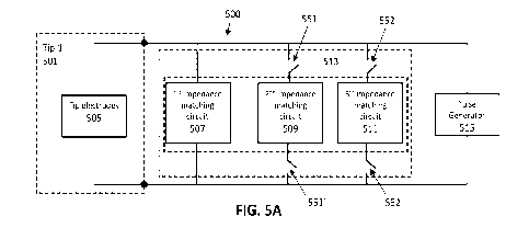
[0096] FIG. 5A schematically illustrates one example of an
apparatus 500 in which a first tip
(Tip 1) 501, including tip electrodes 505, connected to the apparatus so that
the tip is in electrical
communication with pulse generator circuitry 515 of the apparatus. The
apparatus also includes a
plurality of impedance matching circuits, shown in this example as a first
impedance matching
circuit 507, a second impedance matching circuit 509, and a third impedance
matching circuit
511. In some examples fewer (e.g., two) or more (e.g., four, five, six, seven,
etc.) impedance
matching circuits may be used. The apparatus also includes an impedance
matching selector 513
- 20 -
CA 03190840 2023- 2- 24
WO 2022/051178
PCT/US2021/047879
that is shown by the dashed lines surrounding the impedance matching circuits
(e.g., mechanical
switches). In some examples the first impedance matching circuit is not part
of the impedance
matching selector (e.g., the handle may include a "default" impedance matching
circuit). In FIG.
5A the impedance matching selector 513 engages with the tip (not shown) so
that only the first
impedance matching circuit 507 is in electrical communication with the
electrodes 505 on the tip
and the pulse generator. A mechanical engagement (e.g., via a shape encoding
connection)
between the electrode tip 501 and the handle apparatus (e.g., the handle of
the applicator) may
place one or more of the impedance matching circuits within the handle in the
connection
between the electrodes on the tip and the pulse generator. In FIG. 5A only the
first impedance
matching circuit is shown connected (the second and third impedance matching
circuits are
shown disconnected, via switches 551, 551', 552, 552' forming part of the
impedance matching
selector that are opened.
[0097] In FIG. 5B the apparatus 500 of FIG. 5A is shown with a
different tip (tip 2) 501'
attached. In this example, the mechanical connection between the tip 2 and the
handpiece causes
the impedance matching selector 513 to engage a different (or different set
of) one or more of the
impedance matching circuits in parallel with the electrical connection between
tip 2 and the
circuitry generating the pulses (pulse generator circuitry 515). In FIG. 5B,
the second impedance
matching circuit 509 as well as the first impedance matching circuit 507 are
included in the
electrical pathway between the tip electrode 505' and the pulse generator
circuitry 515, as the
impedance matching selector 513 has closed gates 551, 551', placing it in
parallel with the tip
electrodes of the tip 501', thereby setting the impedance matching circuit, as
shown.
[0098] In some examples the impedance matching selector may include
a displaceable
member, such as a plunger 621, as shown and described in FIG. 6. In FIG. 6 the
impedance
matching selector 613 is housed within the handle and includes a displaceable
member, shown in
FIG. 6 as a plunger 621 (also shown in FIG. 7 as plunger 721) that is
configured to be displaced,
for example, by a projection from the electrode tip when the electrode tip is
engaged with the
handle. In this example, the impedance matching selector forms the open distal
face of the
handle (see, e.g., FIG. 4) and includes a distal-facing opening 623 on/into
which the tip couples.
Two or more electrode tip electrical connectors on the tip may engage with
handle electrical
connectors 625, 625' that are accessible through (and/or may be part of) the
impedance matching
selector, as shown in FIG. 6. These connectors may be, for example, high-
current/high power
contacts (e.g., RADSOK high current connectors). In the example shown in FIG.
6, the plunger
621 may travel, e.g., more than 10 mm (e.g., more than 15 mm, more than 19 mm,
etc.) and may
displace an internal set of connectors that may connect to the electrical
pathway between the
- 21 -
CA 03190840 2023- 2- 24
WO 2022/051178
PCT/US2021/047879
handle electrical connectors (that are coupled to the electrode tip electrical
connectors) and the
pulse generator circuitry.
[0099] The impedance matching selector shown in FIG. 6 is
configured as an open switch
(e.g., mechanical switch) that can be driven closed when the correctly keyed
(matching) and
configured electrode tip engages the handle and drives the plunger 621
distally (not shown) into
the housing 602 of the impedance matching selector 613 so that that a set of
internal connectors
engage to close the mechanical switch, putting a second impedance matching
circuit in parallel
contact with the pathway between the pulse generator circuitry and the
electrode of the electrode
tip, as described in FIG. 5, above, thereby adjusting the impedance matching
of the electrode tip,
based and dependent upon the encoding shape connection with the electrode tip.
[0100] For example, FIG. 7 shows a partially exploded view of the
impedance matching
selector of FIG. 6. In this example, the outer housing 702 of the impedance
matching selector
encloses and provides a channel for the plunger 721. The plunger is coupled to
a bias 725
(shown here as a spring, such as a spring having a preload of about 0.1 lb and
a final load of
about 1 lb) and is part of a sled 732. The sled also holds a set of internal
electrical contacts 727,
which in this example are a pair of jumper connects. When the plunger is
driven distally by the
encoding shape connection, e.g., a protrusion on the electrode tip against the
bias, the sled may
also be driven distally and the internal electrical contacts 727 are driven
within an electrically
insulating housing 733 until they contact a complementary set of internal
electrical contacts 737
(e.g., another set of pogo pins) that are also housed within the insulating
housing 733. This may
close the switch(s), placing the downstream impedance matching circuit 741 in
parallel with the
electrical connection between the electrodes in the electrode tip and the
pulse generator circuitry.
In FIG. 7, the impedance matching circuit shown includes a pair of resistors
(150 Ohm resistors),
but other resistor and/or circuit elements may be included. The impedance
matching circuit is
connected via an additional pair of internal connectors 744 (shown as high
current/high voltage
connectors). Pogo pins forming part of the internal connector (e.g., internal
electrical contact)
may be moved to contact a stationary complementary contact to close the switch
and place the
impedance matching circuit (including the two 150 Ohm resistors) in the
electrical pathway
between the electrodes of the electrode tip and the pulse generator circuitry,
as described above.
[0101] In any of the examples described herein the impedance matching
selector may be
configured to prevent arcing or other electrical failure modes, even when
operating at very high
currents and/or voltages and high pulsing rates (e.g., microsecond, sub-
microsecond, such as
nanosecond, etc.). For example as mentioned above, the connectors, and in
particular the internal
connectors, may be rated for use with high current/high voltage. In FIG. 7,
the housing 733
enclosing the first set of internal connectors (e.g., internal electrical
contacts 727 and 737) may
- 22 -
CA 03190840 2023- 2- 24
WO 2022/051178
PCT/US2021/047879
be electrically insulating channels within the housing 733 formed of a high
dielectric material.
The configuration of the internal connectors may also be set up so that the
arrangement between
internal connectors in the "open circuit" (not connected) configuration may
include a significant
air gap to prevent arcing and may be set some minimum creep distance apart
(e.g., at least 10
mm, at least 15 mm, at least 20 mm, at least 25 mm, at least 30 mm, at least
35 mm, at least 40
mm, at least 45 mm, etc.).
[0102] For example, FIG. 8A shows a back view of the impedance
matching selector 813
(shown in FIG. 8B), showing resistor leads 853 that electrically connect the
impedance matching
circuit 844 to the complementary set of internal electrical contacts 837
(shown in FIG. 8C). The
set of internal electrical contacts 837 couple to the first set of internal
electrical contacts 827
when the sled 833 is driven fully proximally when the proper encoding shape
connection is made
with a complimentary electrode tip. The impedance matching circuit 844 may
comprise, for
example, a pair of resistors, such as 150 Ohm resistors.
[0103] FIG. 8C shows a cut away view of an internal section through
the impedance
matching selector 813 when the plunger is not engaged and the internal set of
connectors 827,
837 (which may be referred to herein as internal electrical contacts) are not
engaged but are held
apart by the bias (not shown in FIG. 8C). The spacing 861 between the internal
connectors 827,
837 is a minimum air gap distance. In the example shown in FIG. 8C, the
minimum air gap
distance is greater than 10 mm (e.g., approximately 14.3 mm). Further, the
minimum clearance
distance 855 (shown in bold) is greater than a minimum clearance distance that
avoids arcing; in
FIG. 8C, the minimum clearance distance is at least twice the sum of the air
gap 861 length.
[0104] FIGS. 9A-9B and 10A-10B illustrate other examples of
sections through a portion of
an impedance matching selector 913 and 1013. In FIG. 9B the spacing 961
between the internal
connectors 927, 937 (first and second internal electrical contacts) is an air
gap having a greater
than a minimum air gap distance (in this example, approximately 10 mm). In
FIG. 10B the
spacing 1061 between the internal connectors 1027, 1037 (first and second
internal electrical
contacts) of the impedance matching selector 1013 is an air gap having a
greater than a minimum
air gap distance (e.g., greater than 10 mm, in this example approximately 14.3
mm). In FIGS. 9B
and 10B the dimensions shown for the internal connector(s) are merely examples
that are
intended to be illustrative and should not be considered limiting.
[0105] FIG. 11A shows an example of a cross-sectional view of a
handle portion of a
treatment applicator for use with a pulse generator that includes an impedance
matching selector
similar to that shown in FIGS. 6-10B above. In this example, the handle 1104
includes an
impedance matching selector 1113 at the distal end. The impedance matching
selector includes a
plunger 1121 and a set of internal connectors, including a first internal
electrical contact 1127
- 23 -
CA 03190840 2023- 2- 24
WO 2022/051178
PCT/US2021/047879
and a second internal electrical contact 1137. The first set of internal
electrical contacts is
coupled to the displaceable sled that may move when the plunger 1121 is
displaced by engaging
an encoding shape connection on the electrode tip. The second set of internal
electrical contacts
is statically held and is connected to the impedance matching circuit (e.g.,
impedance matching
resistor 1144). The impedance matching circuit is coupled to the handle
electrical connector
1166 for receiving the electrode tip electrical connectors, but the impedance
matching circuit is
open (unconnected) until the internal mechanical switch is closed by driving
the plunger
proximally, as described above, to close the air gap travel distance 1161 and
connect the internal
connector. In FIG. 11A, the handle electrical connector 1166 is also attached
to a wire (e.g., a
high-voltage wire 1177) and/or a first impedance matching circuit that
connects the handle
electrical connector to the pulse generator. FIG. 11B shows a front view of
the handle of FIG.
11A, showing the distal opening 1123.
[01061 In some examples the impedance matching selector does not
include a displaceable
member, but is instead fixed within the handle, and the electrode tip
electrical connectors form
the encoding shape connection to the impedance matching selector. In this
example the
impedance matching selector includes sets of internal connectors that are
spaced apart and may
each connect to one or more impedance matching circuits. For example, FIG. 12
illustrates one
example of a schematic showing an impedance matching selector having two pairs
of internal
connectors (contacts) 1214, 1216 that are each configured to receive (and make
contact with) an
electrode tip electrical connector; the electrode tip electrical connector is
configured as a pin
1122. In FIG. 12, the pins may be long enough so that they may pass through
the first set of
internal contacts 1214 and extend to the second set of internal contacts 1216
(in some examples
additional internal contacts may be included along the line of travel of the
contacting pin to
facilitate additional contacts with other circuit elements). In some examples
the pin may be short,
so that it only connects to the first set of internal contacts 1214. The first
set of internal contacts
(and in some examples, the second or additional sets of internal contacts) may
be annular, so that
the pin may pass through the internal contact; alternatively the internal
contact may only be
partially annular or may only make contact partially around (and against) the
pin. The first set of
internal contacts 1214 may connect to a first impedance matching circuit
and/or the circuitry for
the pulse generator (shown by HV+ and HV-). The second (and any subsequent)
internal
contacts 1216 may connect to a second impedance matching circuit (shown here
as impedance
matching resistor, R).
[0107] Thus, in FIG. 12, the impedance matching selector is
configured by arranging the
internal connectors (for example, selecting a particular impedance matching
circuit elements
according to the length or other dimensions of the internal connectors), which
may be coupled to
- 24 -
CA 03190840 2023- 2- 24
WO 2022/051178
PCT/US2021/047879
one or more impedance matching circuits, in a spaced apart configuration that
may be connected
by pins of the appropriate encoding shape length. Thus, an encoding shape
connection formed by
the pins of the electrode tip (e.g., the electrode tip electrical connectors)
and the internal contacts
may set the impedance matching for the tip based on which impedance matching
circuits are
engaged by the impedance matching selector.
[0108] FIGS. 13A-13B, 13C-13D and 13E-F illustrate examples of
examples of an
impedance matching selector configured as illustrated schematically in FIG.
12. For example, in
FIG. 13B the impedance matching selector includes a first set of internal
connectors 1314 and
second set of internal connectors 1316 that are arranged in a line with an air
gap between them.
The air gap (and the clearance path between them) may be selected as described
above to have a
minimum clearance distance (e.g., 10 mm or greater, 15 mm or greater, etc.) to
prevent or
minimize arcing.
[0109] In FIG 13B the pins 1322 (e.g., the electrode tip electrical
connectors) are both short,
so that only the first set of internal connectors 1314 are connected to them.
In FIG. 13D the pin
1322' is longer and passes through the first internal connector 1314 (e.g.,
annular), making this
first electrical connection (e.g., with a first impedance circuit ), and then
continuing on to also
contact the second set of internal connectors 1316, completing the circuit to
put the second
impedance matching circuit elements, e.g., 1344, in parallel with the first
internal connection and
therefore the electrode tip, as shown. FIG. 13F illustrates insertion of the
electrode tip electrical
connectors (e.g., the pins) shown in FIG. 13D.
[0110] FIG. 14 illustrates another example of an impedance matching
selector similar to that
shown in FIG. 11A. above. This configuration includes three pins that may be
keyed to form the
encoding shape connection between the electrode tip and the pulse generator
circuitry. The three
(or more) pins may be the same length, rather than relying on pins of
different length to make
different connections with the internal connectors of the impedance matching
selector. For
example in FIG. 14 the upper pin or conductor of the electrode tip connector
is bifurcated into
two pins (a first pin 1404 and a second pin 1406) to make connections with
either a first
matching connector (e.g., a handle electrical connector 1433); or when the
second pin is present,
it may make connection with a second impedance matching circuit 1444 (shown as
impedance
matching resistor, R). A third pin completes the connection with the first
impedance matching
circuit and/or pulse generator (e.g., HV-).
[0111] FIGS. 15A-15C and 16A-16C show examples of tips and handles
configured so that
the impedance matching selector is based on the number, position and/or length
of the pins
(electrode pins or connectors) when the tip engages with the handle. For
example, in FIGS. 15A-
15C and 16A-16C, the apparatus is similar to the one shown schematically in
FIG. 14. In this
- 25 -
CA 03190840 2023- 2- 24
WO 2022/051178
PCT/US2021/047879
example the pins extend from the proximal end of the electrode tip 1501 or
1601, and include a
first pin 1504 or 1604, a second pin 1606 and (in some examples) a third pin
1508 or 1608. The
first pin 1604 is electrically continuous with the second pin 1606. In FIG.
15A the tip includes
only a first pin and a third pin; thus the second pin is not present and does
not connect with an
internal connector (shown in FIGS. 16A-16B) and, therefore, the second
impedance matching
circuit (e.g., impedance matching resistor 1544).
[0112] In contrast, FIG. 16B shows an example in which all three
pins are present. The
second pin 1606 makes electrical contact with the internal connector so that
the second
impedance matching circuit (e.g., impedance matching resistor) 1544 is
connected in parallel
with the connection between the tip electrodes and the pulse generator
circuitry. FIG. 16B
illustrates an example of a configuration similar to the one shown in FIG.
15B, but with the
electrode tip 1601 having 3 pins 1604, 1606, 1608, and shown disengaged from
the handle
connector 1620. In FIG. 16B, which is similar to the configuration shown in
FIG. 15B, the tip
1601 is engaged with the handle connector 1620, so that the encoding shape
connection is made
by the electrode tip electrical connectors.
[0113] In some examples multiple different impedance matching
circuits may be selected by
the impedance matching selector based on one or more encoding shape
engagements between the
electrode tip and the impedance matching selector. FIG. 17 schematically
illustrates an example
of a configuration in which the impedance matching selector includes a
plurality of internal
contacts, similar to that shown in FIG. 11A, but with cross-connected
impedance matching
circuits. For example, in FIG. 17, four internal connectors are shown. A first
internal connector
1771 and a third internal connector 1773 may be configured as annular
connectors, while a
second internal connector 1775 and a fourth internal connector 1777a may be
annular or not
(e.g., shown as pins in FIG. 17). Each internal connector is connected to an
impedance matching
circuit and these circuits arc cross-connected (e.g., the first and fourth
connectors are connected,
the second and third connectors are connected, etc.).
[0114] FIGS. 18A-18G illustrate the use of an apparatus such as
that shown schematically in
FIGS. 17. FIG. 18A shows a portion of a handle and a tip disconnected from
each other, FIG.
18F shows a portion of a handle and a tip connected to each other, while FIGS.
18B-18E
illustrate different configuration for engage a tip to the handle to select
the impedance matching
to the particular tip configurations shown.
[0115] In FIG. 18B, when both pins 1846, 1846' of the electrode tip
1801 are short and the
electrode tip is coupled with the handle, no additional impedance matching
circuit elements are
connected between the electrodes of the electrode tip and the pulse generator
circuitry. In FIG.
18C, the first pin 1846 is long and contacts both a first internal connector
1871 and a second
- 26 -
CA 03190840 2023- 2- 24
WO 2022/051178
PCT/US2021/047879
internal connector 1873 while the second pin 1846' is short and only contacts
a third internal
connector 1875; this configuration connects only the second impedance matching
circuit
elements (e.g., 1844) in parallel with the connection between the electrode
tip and the pulse
generator circuitry (e.g., setting the impedance matching of the tip). In FIG.
18D, the first pin
1846 is short and contacts only the first internal connector 1871 but not the
second internal
connector 1873, while the second pin 1846' is long and contacts both the third
internal connector
1875 and the fourth internal connector 1877; this configuration connects only
the third
impedance matching circuit 1844' in parallel with the connection between the
electrode tip and
the pulse generator circuitry. In FIG. 18E, both the first pin 1846 and the
second pin 1846' are
long; the first pin 1846 contacts both the first internal connector 1871 and
second internal
connector 1873 and the second pin 1846' contacts both the third internal
connector 1875 and the
fourth internal connector 1877; this configuration connects both the second
impedance matching
circuit 1844 and the third impedance matching circuit 1844' in parallel with
the connection
between the electrode tip and the pulse generator circuitry. FIG. 18G
illustrates insertion of a tip
such as the electrode tip shown in FIG. 18C.
[01161 FIG. 19 illustrates examples of electrode tips having
different keying, with and
without a displaceable member. In FIG. 19 the tip on the left (1901) includes
a protrusion (e.g., a
post or plunger 1919) that is configured to push and engage the impedance
matching selector on
the handle. Separately, electrode tip electrical conductors (not shown in FIG.
19) may make
electrical contact with handle electrical connectors, which may be part of the
impedance
matching selector, or separate. In FIG. 19, the tip on the right (1903) does
not include a
displaceable member, such as protrusion and is flat in this region 1921.
[0117] Any of the apparatuses described herein may be used as part
of a method for
automatically and/or mechanically setting the impedance matching for a variety
of different
electrode tips. For example, FIG. 20 illustrates an example of a method 2000
of selecting an
impedance circuit for a removable electrode tip of a treatment or pulse
applicator. In FIG. 20, the
method includes coupling (e.g., removably coupling) a first electrode tip to a
handle of an
applicator (step 2001). The electrode tip may be electrically and/or
mechanically coupled.
Coupling may include engaging a first connector (encoding shape connector)
from the first
electrode tip with an impedance matching selector of the handle, wherein the
impedance
matching selector selectively places at least one electrode tip electrical
connector of the first
electrode tip in electrical communication with one or more impedance matching
circuits based
on the first encoding shape connector (step 2003). This will allow a pulse
generator to be in
electrical communication with a plurality of electrodes in the first electrode
tip through the
selected one or more impedance matching circuits. This may further include, in
some examples,
- 27 -
CA 03190840 2023- 2- 24
WO 2022/051178
PCT/US2021/047879
electrically isolating each of the impedance matching circuits within the
handle to prevent arcing.
This may be accomplished by maintaining a minimum clearance distance between
a) internal
electrical contacts of the impedance matching selector that are in electrical
communication with
the at least one electrode tip electrical connector and b) internal electrical
connectors of the
impedance matching selector that are in electrical communication with any of
the impedance
matching circuit elements not selected by the impedance matching selector to
be in electrical
communication with the at least one electrode tip electrical connector of the
electrode tip (step
2005).
[0118] Although the methods and apparatuses described herein focus
primarily on
removably coupling an electrode tip to a handle of an applicator, any of these
methods and
apparatuses may instead be used for irreversibly coupling an electrode tip to
a handle or
applicator; for example in some examples the handle may be single-use or
limited use (including
disposable).
[0119] In some examples, the method may optionally include applying
a pulsed electrical
energy from the first electrode tip (step 2007). In any of the methods
described herein, the
application of the pulse electrical energy may be for cosmetic and/or for
therapeutic purposes. In
some examples these methods may be strictly for cosmetic purposes, e.g., to
treat any cosmetic
defect or condition, such as a blemish.
[0120] Optionally, any of these methods may further include
removing the electrode tip and
applying another, different, electrode tip (step 2009); the handle of the
pulse applicator may
again automatically set the impedance matching for the tip based on the
encoding shape between
the different electrode tip and the handle (e.g., between the electrode tip
and an impedance
matching selector in the handle).
[0121] Any of the methods (including user interfaces) described
herein may be implemented
as software, hardware or firmware, and may be described as a non-transitory
computer-readable
storage medium storing a set of instructions capable of being executed by a
processor (e.g.,
computer, tablet, smartphone, etc.), that when executed by the processor
causes the processor to
control perform any of the steps, including but not limited to: displaying,
communicating with
the user, analyzing, modifying parameters (including timing, frequency,
intensity, etc.),
determining, alerting, or the like.
[0122] When a feature or element is herein referred to as being
"on" another feature or
element, it can be directly on the other feature or element or intervening
features and/or elements
may also be present. In contrast, when a feature or element is referred to as
being "directly on"
another feature or element, there are no intervening features or elements
present. It will also be
understood that, when a feature or element is referred to as being
"connected", "attached" or
- 28 -
CA 03190840 2023- 2- 24
WO 2022/051178
PCT/US2021/047879
"coupled" to another feature or element, it can be directly connected,
attached or coupled to the
other feature or element or intervening features or elements may be present.
In contrast, when a
feature or element is referred to as being "directly connected", "directly
attached" or "directly
coupled" to another feature or element, there are no intervening features or
elements present.
Although described or shown with respect to one embodiment, the features and
elements so
described or shown can apply to other embodiments. It will also be appreciated
by those of skill
in the art that references to a structure or feature that is disposed
"adjacent" another feature may
have portions that overlap or underlie the adjacent feature.
[0123] Terminology used herein is for the purpose of describing
particular embodiments
only and is not intended to be limiting. For example, as used herein, the
singular forms "a", "an"
and "the" are intended to include the plural forms as well, unless the context
clearly indicates
otherwise. As used herein, the term "and/or" includes any and all combinations
of one or more of
the associated listed items and may be abbreviated as "/".
[0124] Spatially relative terms, such as "under", "below". "lower",
"over", "upper" and the
like, may be used herein for ease of description to describe one element or
feature's relationship
to another element(s) or feature(s) as illustrated in the figures. It will be
understood that the
spatially relative terms are intended to encompass different orientations of
the device in use or
operation in addition to the orientation depicted in the figures. For example,
if a device in the
figures is inverted, elements described as "under" or "beneath" other elements
or features would
then be oriented "over" the other elements or features. Thus, the exemplary
term "under" can
encompass both an orientation of over and under. The device may be otherwise
oriented (rotated
90 degrees or at other orientations) and the spatially relative descriptors
used herein interpreted
accordingly. Similarly, the terms "upwardly", "downwardly". "vertical",
"horizontal" and the like
are used herein for the purpose of explanation only unless specifically
indicated otherwise.
[0125] Although the terms -first" and -second" may be used herein to
describe various
features/elements (including steps), these features/elements should not be
limited by these terms,
unless the context indicates otherwise. These terms may be used to distinguish
one
feature/element from another feature/element. Thus, a first feature/element
discussed below
could be termed a second feature/element, and similarly, a second
feature/element discussed
below could be termed a first feature/element without departing from the
teachings of the present
disclosure.
[0126] Throughout this specification and the claims which follow,
unless the context
requires otherwise, the word "comprise", and variations such as -comprises"
and "comprising"
means various components can be co-jointly employed in the methods and
articles (e.g.,
compositions and apparatuses including device and methods). For example, the
term
- 29 -
CA 03190840 2023- 2- 24
WO 2022/051178
PCT/US2021/047879
"comprising" will be understood to imply the inclusion of any stated elements
or steps but not
the exclusion of any other elements or steps.
[0127] As used herein in the specification and claims, including as
used in the examples and
unless otherwise expressly specified, all numbers may be read as if prefaced
by the word "about"
or -approximately," even if the term does not expressly appear. The phrase
"about" or
"approximately" may be used when describing magnitude and/or position to
indicate that the
value and/or position described is within a reasonable expected range of
values and/or positions.
For example, a numeric value may have a value that is +/- 0.1% of the stated
value (or range of
values), +/- 1% of the stated value (or range of values), +/- 2% of the stated
value (or range of
values), +/- 5% of the stated value (or range of values), +/- 10% of the
stated value (or range of
values), etc. Any numerical values given herein should also be understood to
include about or
approximately that value, unless the context indicates otherwise. For example,
if the value "10"
is disclosed, then "about 10" is also disclosed. Any numerical range recited
herein is intended to
include all sub-ranges subsumed therein. It is also understood that when a
value is disclosed that
"less than or equal to" the value, "greater than or equal to the value" and
possible ranges between
values are also disclosed, as appropriately understood by the skilled artisan.
For example, if the
value "X" is disclosed the "less than or equal to X" as well as "greater than
or equal to X" (e.g.,
where X is a numerical value) is also disclosed. It is also understood that
the throughout the
application, data is provided in a number of different formats, and that this
data, represents
endpoints and starting points, and ranges for any combination of the data
points. For example, if
a particular data point "10" and a particular data point "15" are disclosed,
it is understood that
greater than, greater than or equal to, less than, less than or equal to, and
equal to 10 and 15 are
considered disclosed as well as between 10 and 15. It is also understood that
each unit between
two particular units are also disclosed. For example, if 10 and 15 are
disclosed, then 11, 12, 13,
and 14 are also disclosed.
[0128] Although various illustrative embodiments are described
above, any of a number of
changes may be made to various embodiments without departing from the scope of
the
disclosure as described by the claims. For example, the order in which various
described method
steps are performed may often be changed in alternative embodiments, and in
other alternative
embodiments one or more method steps may be skipped altogether. Optional
features of various
device and system embodiments and examples may be included in some
embodiments/examples
and not in others, and some feature(s) described in reference to one example
may be incorporated
in the other provided examples. Therefore, the foregoing description is
provided primarily for
exemplary purposes and should not be interpreted to limit the scope of the
invention as it is set
forth in the claims.
- 30 -
CA 03190840 2023- 2- 24
WO 2022/051178
PCT/US2021/047879
[0129] The examples and illustrations included herein show, by way
of illustration and not of
limitation, specific embodiments in which the subject matter may be practiced.
As mentioned,
other embodiments may be utilized and derived there from, such that structural
and logical
substitutions and changes may be made without departing from the scope of this
disclosure. Such
embodiments of the inventive subject matter may be referred to herein
individually or
collectively by the term "invention" merely for convenience and without
intending to voluntarily
limit the scope of this application to any single invention or inventive
concept, if more than one
is, in fact, disclosed. Thus, although specific embodiments have been
illustrated and described
herein, any arrangement calculated to achieve the same purpose may be
substituted for the
specific embodiments shown. This disclosure is intended to cover any and all
adaptations or
variations of various embodiments. Combinations of the above embodiments, and
other
embodiments not specifically described herein, will be apparent to those of
skill in the art upon
reviewing the above description.
- 31 -
CA 03190840 2023- 2- 24