Note: Descriptions are shown in the official language in which they were submitted.
WO 2022/046786
PCT/US2021/047373
ARTICLE CARRIER AND BLANK THEREFOR
TECHNICAL FIELD
The present invention relates to article carriers and to blanks for forming
the same.
More specifically, but not exclusively, the invention relates to a carrier of
the top-
gripping type having one or more apertures for receiving and retaining an
article
therein and a top cover affixed thereto.
BACKGROUND
In the field of packaging, it is known to provide cartons for carrying
multiple articles.
Cartons are well known in the art and are useful for enabling consumers to
transport,
store and access a group of articles for consumption. For cost and
environmental
considerations, such cartons or carriers need to be formed from as little
material as
possible and cause as little wastage in the materials from which they are
formed as
possible. Further considerations are the strength of the carton and its
suitability for
holding and transporting large weights of articles. It is desirable that the
contents of
the carton are secure within the carton.
It is well known to provide top gripping article carriers in which an aperture
is formed
in a panel of the carrier, wherein tabs are struck from said aperture. The
tabs are
displaced out of the plane of said panel when an article is received in the
aperture,
wherein said tabs engage the article generally about a flange or lip of the
article.
The present invention seeks to provide an improvement in the field of cartons,
typically
formed from paperboard or the like.
SUMMARY
A first aspect of the invention provides an article carrierfor engaging at
least one article.
The article carrier comprises a pair of spaced apart panels including a cover
panel and
an engaging panel. The article carrier comprises a male locking tab, formed
from the
cover panel, for connecting the cover panel with the engaging panel. The
locking tab
is hingedly connected to the cover panel along a notional fold line which may
extend
obliquely with respect to at least one of an end edge and a side edge of the
cover
panel. The locking tab provides a retaining device securing the cover panel in
position
- 1 -
CA 03190943 2023- 2- 24
WO 2022/046786
PCT/US2021/047373
above the engaging panel. At least a portion of the locking tab is disposed
between
the upper panel and the lower panel to maintain a spacing therebetween.
Optionally, the engaging panel has at least one article-engaging structure for
engaging
a part of the at least one article.
Optionally, the locking tab comprises opposed shoulders spaced apart from the
hinged
connection between the locking tab and the cover panel.
Optionally, the locking tab forms a cushioning flap of a handle structure.
Optionally, the locking tab defines a first opening in the cover panel to
which it is hinged,
the first opening is disposed in registry with a second opening in the
engaging panel.
Optionally, the first and second openings together define a passage through
the pair
of spaced apart panels.
Optionally, the second panel limits travel of the locking tab.
Optionally, an edge of the engaging panel provided by the second opening
provides
an end stop with which the locking tab is engageable.
Optionally, the locking tab comprises a bridging region extending across a gap
or void
between the cover panel and the engaging panel.
Optionally, the bridging region is defined between the notional fold line and
shoulders
provided by the locking tab.
Optionally, the cover panel comprises a pair of covering flaps each of which
is hingedly
connected to the engaging panel by a respective side panel.
Optionally, the locking tab comprises one or more separation elements defining
an
engaging edge of an engaging portion, the engaging edge being arranged to
engage
a first surface of the lower panel.
- 2 -
CA 03190943 2023- 2- 24
WO 2022/046786
PCT/US2021/047373
Optionally, the one or more separation elements define a support edge of a
wing
portion, the support edge being arranged to engage a second surface of the
lower
panel, the second surface of the lower panel opposes the first surface of the
lower
panel.
Optionally, the one or more separation elements are provided by a cut line.
Optionally, the cut line is obliquely oriented with respect to the hinged
connection
between locking tab and the upper panel.
Optionally, the locking tab is obliquely oriented with respect to the upper
and lower
panels.
Optionally, the upper panel comprises a composite cover panel formed from an
upper
covering flap and a lower covering flap, the upper covering flap and the lower
covering
flap at least partially overlapping, wherein the upper covering flap comprises
a first
male locking tab and the lower covering flap comprises an opening defined by a
second male locking tab.
Optionally, the second male locking tab is equal to or greater in dimension
than the
first male locking tab.
Optionally, the locking tab asymmetric about a notional line bisecting the
hinged
connection between the locking tab and the panel to which it is hinged.
Optionally, the locking tab comprises a pair of shoulders providing engaging
edges, a
first one of the engaging edges being disposed in closer proximity to the
hinged
connection than the second one of the engaging edges.
Optionally, the first male locking tab is hingedly connected to the upper
covering flap
by a first hinged connection having a first fold resistance and the second
male locking
tab is hingedly connected to the lower covering flap by a second hinged
connection
- 3 -
CA 03190943 2023- 2- 24
WO 2022/046786
PCT/US2021/047373
having a second fold resistance, the second fold resistance being smaller in
magnitude
than the first fold resistance.
A second aspect of the invention provides an article carrier for engaging at
least one
article. The article carrier comprises an engaging panel having article
engaging
apertures for receiving upper portions of articles. A cover panel is disposed
at a
position spaced above the engaging panel. A connecting structure is provided
for
connecting the cover panel with the engaging panel. The engaging panel and the
cover panel may be formed from separate blanks respectively.
Optionally, the connecting structure comprises a first connecting element for
securing
at least one first region of the cover panel to the articles.
Optionally, the connecting structure comprises a second connecting element for
securing at least one second region of the cover panel to the engaging panel.
Optionally, the connecting structure comprises a first connecting element for
securing
marginal regions of the cover panel to the articles.
Optionally, the connecting structure comprises a second connecting element for
securing a medial region of the cover panel to the engaging panel.
Optionally, the article carrier further comprises an article stabilizing
structure extending
downward from the engaging panel.
Optionally, the article stabilizing structure is hingedly connected to the
engaging panel.
Optionally, the article stabilizing structure encircles a group of articles
being packaged.
Optionally, the article carrier further comprises an article stabilizing
structure
connected to the engaging panel and extending from the engaging panel in a
direction
away from the cover panel.
Optionally, the article stabilizing structure encircles a group of articles
being packaged.
- 4 -
CA 03190943 2023- 2- 24
WO 2022/046786
PCT/US2021/047373
Optionally, the connecting structure comprises a locking tab having shoulders
spaced
apart from a hinged connection between the locking tab and the panel to which
it is
hinged, in this way the shoulders engage a second panel spaced apart from said
panel
to which it is hinged.
Optionally, the cover panel comprises marginal regions folded about shoulders
of the
articles forming an article group being packaged.
Optionally, the second end flap comprises an end panel portion hingedly
connected to
the engaging panel and a top flap portion hingedly connected to the end panel
portion.
Optionally, one of the pair of hinged panels is hingedly connected to the top
flap portion.
Optionally, the other one of the pair of hinged panels is hingedly connected
to the first
end flap and wherein the first end flap is arranged to be disposed in face
contacting
relationship with the cover panel.
Optionally, at least one of the pair of hinged panels is defined, at least in
part, by a
pair of divergently arranged fold lines.
Optionally, at least one of the pair of hinged panels is defined, at least in
part, by a
pair of parallel fold lines.
Optionally, the other one of the pair of hinged panels is defined, at least in
part, by a
pair of parallel first fold lines, and wherein the first fold lines are
obliquely oriented with
respect to at least one second fold line hingedly connecting the cover panel
to the
engaging panel.
Optionally, the other one of the pair of hinged panels is defined, at least in
part, by a
pair of parallel first fold lines, and wherein the first fold lines are
obliquely oriented with
respect to at least one third fold line hingedly connecting the second end
flap to the
engaging panel.
- 5 -
CA 03190943 2023- 2- 24
WO 2022/046786
PCT/US2021/047373
Optionally, the first end flap is hingedly connected to the cover panel by a
fourth fold
line, the fourth fold line being divergently arranged with respect to a fifth
fold line
hingedly connecting the second end flap to the engaging panel.
Optionally, the first end flap is hingedly connected to the cover panel by a
fourth fold
line, the fourth fold line being obliquely oriented with respect to at least
one second
fold line hingedly connecting the cover panel to the engaging panel.
A third aspect of the invention provides an article carrier for engaging at
least one
article. The article carrier comprises a pair of spaced panels including a
cover panel
and an engaging panel. The article carrier comprises a male locking tab formed
from
the cover panel for connecting the cover panel with the engaging panel. The
locking
tab is hingedly connected to the cover panel along a fold line. The fold line
lies upon
a notional line which extends obliquely with respect to at least one of an end
edge and
a side edge of the cover panel.
A fourth aspect of the invention provides a blank for forming an article
carrier. The
blank comprises a pair of panels arranged to be spaced apart in a setup
carrier. The
pair of panels includes a cover panel and an engaging panel. The blank further
comprises a male locking tab formed from the cover panel for connecting the
cover
panel and the engaging panel. The locking tab is hingedly connected to the
cover
panel along a notional fold line which extends obliquely with respect to at
least one of
an end edge and a side edge of the cover panel.
A fifth aspect of the invention provides a blank for forming an article
carrier. The blank
comprises a pair of panels arranged to be spaced apart in a setup carrier. The
pair of
panels includes a cover panel and an engaging panel. The blank further
comprises a
male locking tab formed from the cover panel for connecting the cover panel
and the
engaging panel. The locking tab is hingedly connected to the cover panel along
a fold
line. The fold line lies upon a notional line which extends obliquely with
respect to at
least one of an end edge and a side edge of the cover panel.
A sixth aspect of the invention provides a pair of blanks for forming an
article carrier.
The pair of blanks comprises a first blank having an engaging panel comprising
article
- 6 -
CA 03190943 2023- 2- 24
WO 2022/046786
PCT/US2021/047373
engaging apertures for receiving upper portions of articles, and a second
blank
separate from the first blank. The second blank comprises a cover panel
configured
to be disposed at a position spaced above the engaging panel in a set up
condition.
The pair of blanks comprises a connecting structure for connecting the cover
panel
and the engaging panel.
Optionally, the second blank comprises a second connecting structure for
connecting
the cover panel to the articles.
A seventh aspect of the invention provides an article carrier for engaging at
least one
article. The article carrier comprises spaced apart panels including an upper
panel and
a lower panel. The article carrier comprises a locking tab formed from the
upper panel.
The locking tab provides a retaining device securing the upper panel in
position above
the lower panel. The locking tab serves as a spacer between the upper panel
and the
lower panel.
Optionally, the locking tab protrudes downward through an opening in the lower
panel
such that the locking tab engages the perimeter of the opening in the lower
panel.
Optionally, the upper panel comprises a composite cover panel formed from two
overlapping panels, an upper covering flap comprising the locking tab and a
lower
covering flap comprising an opening, wherein the opening is defined by one or
more
female tabs.
Optionally, the locking tab engages with at least one of the female tabs.
Optionally, at least one of the female tabs protrudes downward through an
opening in
the lower panel.
Optionally, the locking tab engages the perimeter of the opening in the lower
panel
and engages a recessed portion of at least one of the female tabs.
- 7 -
CA 03190943 2023- 2- 24
WO 2022/046786
PCT/US2021/047373
Optionally, the locking tab comprises one or more separation elements defining
an
engaging edge of an engaging portion, the engaging edge being arranged to
engage
a first surface of the lower panel.
Optionally, the one or more separation elements define a support edge of a
wing
portion, the support edge being arranged to engage a second surface of the
lower
panel, the second surface of the lower panel opposes the first surface of the
lower
panel.
Optionally, the one or more separation elements are provided by a cut line.
An eighth aspect of the invention provides an article carrier for engaging at
least one
article. The article carrier comprises a tubular structure formed in part by a
cover panel,
an engaging panel and opposed side panels. The carrier comprises a gusseted
end
closure structure for forming a rigid hinged connection along at least one of
upper and
lower end edges of the tubular structure.
A ninth aspect of the invention provides an article carrier for engaging at
least one
article. The article carrier comprises a tubular structure formed in part by a
cover panel,
an engaging panel and opposed side panels. The carrier comprises a gusseted
end
closure structure for forming a beam structure along at least one end of the
tubular
structure.
Optionally, the carrier comprises a gusset provided by a pair of hinged panels
connecting between a first end flap hingedly connected to the cover panel and
second
end flap hingedly connected to the engaging panel.
A tenth aspect of the invention provides an article carrier for engaging at
least one
article. The article carrier comprises a plurality of panels forming a tubular
structure
including a top panel and a bottom panel. The carrier comprises a first end
flap
hingedly connected to the top panel and second end flap hingedly connected to
the
bottom panel. A gusset, provided by a pair of hinged panels, connects between
the
first end flap and the second end flap.
- 8 -
CA 03190943 2023- 2- 24
WO 2022/046786
PCT/US2021/047373
Optionally, the pair of hinged panels is hingedly connected to a first portion
of the
second end flap arranged substantially parallel to the top panel.
Optionally, the first portion of the second end flap is hingedly connected to
a second
portion of the second end flap, the second portion of the second end flap
extending
between the top panel and the bottom panel.
An eleventh aspect of the invention provides an article carrier for engaging
at least
one article. The article carrier comprises a main panel having an article
retention
structure and a second panel hingedly connected to the main panel by a fold
line. The
article retention structure comprises an engaging tab located proximate the
fold line
between the main panel and the second panel. The engaging tab comprises a pair
of
non-linear side edges defined by cuts each having a first end on the distal
end edge
of the engaging tab. The cuts extend from their respective first ends toward
the fold
line and turn away from each other. The cuts maintain a spaced apart
relationship
from the fold line. The cuts terminate at respective second ends which are
spaced
apart from the fold line.
A twelfth aspect of the invention provides a blank for forming an article
carrier. The
blank comprises a pair of panels arranged to be spaced apart in a setup
carrier. The
pair of panels includes an upper panel and a lower panel. The blank comprising
a
locking tab formed from the upper panel. The locking tab provides a retaining
device
for securing the upper panel in position above the lower panel. The locking
tab serves
as a spacer between the upper panel and the lower panel.
A thirteenth aspect of the invention provides a blank for forming an article
carrier. The
blank comprises a cover panel, an engaging panel and opposed side panels for
forming a tubular structure. The blank comprises a gusseted end closure
structure for
forming a rigid hinged connection along at least one of upper and lower end
edges of
the tubular structure in set up carrier.
A fourteenth aspect of the invention provides a blank for forming an article
carrier. The
blank comprises a cover panel, an engaging panel and opposed side panels for
forming a tubular structure. The blank comprises a gusseted end closure
structure for
- 9 -
CA 03190943 2023- 2- 24
WO 2022/046786
PCT/US2021/047373
forming a beam structure along at least one end of the tubular structure in
set up
carrier.
A fifteenth aspect of the invention provides a blank for forming an article
carrier. The
blank comprises a plurality of panels for forming a tubular structure
including a top
panel and a bottom panel. The blank comprises a first end flap hingedly
connected to
the top panel and second end flap hingedly connected to the bottom panel. A
gusset,
provided by a pair of hinged panels, hingedly connects between the first end
flap and
the second end flap.
A sixteenth aspect of the invention provides a blank for forming an article
carrier. The
blank comprises a main panel having an article retention structure and a
second panel
hingedly connected to the main panel by a fold line. The article retention
structure
comprises an engaging tab located proximate the fold line between the main
panel
and the second panel. The engaging tab is defined, at least in part, by a pair
of non-
linear side edges defined by cuts. Each cut having a first end on the distal
end edge
of the engaging tab. The cuts extend from their respective first ends toward
the fold
line and turn away from each other. The cuts maintain a spaced apart
relationship
from the fold line. The cuts terminate at respective second ends which are
spaced
apart from the fold line.
Further aspects of the invention provide an article carrier for engaging at
least one
article and a blank for forming the article carrier. The article carrier
comprises spaced
apart panels including an upper panel and a lower panel. The article carrier
comprises
a handle structure formed in part from the upper panel and in part from the
lower panel.
The handle structure comprises a cushioning flap, formed from the upper panel
and
folded into a gap between the upper and lower panels, the cushioning flap
provides a
locking tab. The locking tab provides a retaining device securing the upper
panel in
position above the lower panel.
Optionally, the locking tab is hingedly connected to the cushioning flap by a
fold line.
- 10 -
CA 03190943 2023- 2- 24
WO 2022/046786
PCT/US2021/047373
Optionally, the locking tab comprises one or more separation elements defining
an
engaging edge of an engaging portion, the engaging edge being arranged to
engage
a first surface of the lower panel.
Optionally, the one or more separation elements define a support edge of a
wing
portion of the cushioning flap, the support edge being arranged to engage a
second
surface of the lower panel, the second surface of the lower panel opposes the
first
surface of the lower panel. The second surface faces towards the upper panel.
Optionally, the one or more separation elements are provided by a cut line.
Within the scope of this application, it is envisaged or intended that the
various aspects,
embodiments, examples, features and alternatives set out in the preceding
paragraphs, in the claims and/or in the following description and drawings may
be
considered or taken independently or in any combination thereof.
Features or elements described in connection with, or relation to, one
embodiment are
applicable to all embodiments unless there is an incompatibility of features.
One or
more features or elements from one embodiment may be incorporated into, or
combined with, any of the other embodiments disclosed herein, said features or
elements extracted from said one embodiment may be included in addition to, or
in
replacement of one or more features or elements of said other embodiment.
A feature, or combination of features, of an embodiment disclosed herein may
be
extracted in isolation from other features of that embodiment. Alternatively,
a feature,
or combination of features, of an embodiment may be omitted from that
embodiment.
BRIEF DESCRIPTION OF THE DRAWINGS
Exemplary embodiments of the invention will now be described with reference to
the
accompanying drawings, in which:
Figure 1A is a plan view from above of a blank for forming a carrier according
to a first embodiment;
Figure 1B is an enlarged view of an article retention device according to the
first
embodiment;
- 11 -
CA 03190943 2023- 2- 24
WO 2022/046786
PCT/US2021/047373
Figure 2 illustrates a stage of construction of a carrier from the blank of
Figure
1A;
Figure 3 is a perspective view from above of a carrier formed from the blank
of
Figure 1A;
Figure 4 is a perspective view from above of a portion of the carrier of
Figure 3;
Figure 5A is a plan view from above of a blank for forming a carrier according
to a second embodiment;
Figure 5B is an enlarged view of a first article retention device according to
the
second embodiment;
Figure 50 is an enlarged view of a second article retention device according
to
the second embodiment;
Figure 6 is a plan view from above of a first blank for forming a package
according to a third embodiment;
Figure 7 is a plan view from above of a second blank for forming a package
according to the third embodiment;
Figures 8 and 9 illustrate stages of construction of a package from the blanks
of Figures 6 and 7;
Figure 10 is a perspective view from above of a carrier formed from the blanks
of Figures 6 and 7;
Figure 11 is a perspective view from above of a portion of the carrier of
Figure
10;
Figure 12A is a plan view from above of a blank for forming a carrier
according
to a fourth embodiment;
Figure 12B is an enlarged view of an article retention device according to the
fourth embodiment;
Figures 13 to 17 illustrate stages of construction of a carrier from the blank
of
Figure 12A;
Figure 18 is a perspective view from above of a carrier formed from the blank
of Figure 12A;
Figure 19 is a perspective view from above of a portion of the carrier of
Figure
18;
Figure 20 is a plan view from above of a blank for forming a carrier according
to a fifth embodiment;
- 12 -
CA 03190943 2023- 2- 24
WO 2022/046786
PCT/US2021/047373
Figure 21 is a plan view from above of a blank for forming a carrier according
to a sixth embodiment;
Figure 22 is a perspective view from above of a carrier formed from the blank
of Figure 21;
Figure 23 is an enlarged perspective view from above of a portion of the
carrier
of Figure 22 in which a locking tab has been unlocked and folded outwardly for
illustrative purposes;
Figure 24 is an enlarged perspective view from above of a portion of the
carrier
of Figure 22;
Figure 25 is an enlarged plan view from above of a portion of the blank of
Figure
21;
Figure 26 is a plan view from above of a blank for forming a carrier according
to a seventh embodiment;
Figure 27A and 27B are an enlarged plan views from above of portions of the
blank of Figure 26;
Figure 28A is an enlarged perspective view from above of a portion of a
carrier
formed from the blank of Figure 26;
Figure 28B is a perspective view from above of the portion of the carrier
shown
in Figure 28A in which a locking tab has been unlocked and folded outwardly
for
illustrative purposes;
Figure 29 is a plan view from above of a blank for forming a carrier according
to an eighth embodiment;
Figure 30A is a plan view from above of a blank for forming a carrier
according
to a ninth embodiment;
Figure 30B is an enlarged plan view from above of a portion of the blank of
Figure 30A;
Figures 31A and 31B are perspective views of a lock mechanism in a carrier
formed from the blank of Figure 30A; and
Figures 32 and 33 illustrate stages of construction of a carrier from the
blank of
Figure 30A.
DETAILED DESCRIPTION OF EMBODIMENTS
Detailed descriptions of specific embodiments of the package, blanks and
carriers are
disclosed herein. It will be understood that the disclosed embodiments are
merely
- 13 -
CA 03190943 2023- 2- 24
WO 2022/046786
PCT/US2021/047373
examples of the way in which certain aspects of the invention can be
implemented
and do not represent an exhaustive list of all of the ways the invention may
be
embodied. As used herein, the word "exemplary" is used expansively to refer to
embodiments that serve as illustrations, specimens, models, or patterns.
Indeed, it will
be understood that the packages, blanks and carriers described herein may be
embodied in various and alternative forms. The Figures are not necessarily to
scale
and some features may be exaggerated or minimized to show details of
particular
components. Well-known components, materials or methods are not necessarily
described in great detail in order to avoid obscuring the present disclosure.
Any
specific structural and functional details disclosed herein are not to be
interpreted as
limiting, but merely as a basis for the claims and as a representative basis
for teaching
one skilled in the art to variously employ the invention.
Referring to Figure 1, there is shown a plan view of a blank 10 which is
capable of
forming a carton or carrier 90, as shown in Figure 3, for containing and
carrying a
group of primary products such as, but not limited to, bottles or cans,
hereinafter
referred to as articles B. The blank 10 forms a secondary package for
packaging at
least one primary product container or package.
Alternative blanks 110; 210A, 210B; 310; 410; 510; 610; 710; 810 are shown in
Figures
5,6, 7, 12, 20, 21, 26, 29, and 30A for forming carton or carrier 290; 390;
590; 690;
890, as shown in Figures 9, 18, 21, 28A, and 32, for containing and carrying a
group
of primary products such as, but not limited to, bottles or cans, hereinafter
referred to
as articles B.
In the embodiments detailed herein, the terms "carton" and "carrier" refer,
for the non-
limiting purpose of illustrating the various features of the invention, to a
container for
engaging and carrying articles, such as primary product containers. It is
contemplated
that the teachings of the invention can be applied to various product
containers, which
may or may not be tapered and/or cylindrical. Exemplary containers include
bottles
(for example metallic, glass or plastics bottles), cans (for example aluminium
cans),
tins, pouches, packets and the like.
- 14 -
CA 03190943 2023- 2- 24
WO 2022/046786
PCT/US2021/047373
The blanks 10; 110; 210A, 210B; 310; 410; 510; 610; 710; 810 are formed from a
sheet of suitable substrate. It is to be understood that, as used herein, the
term
"suitable substrate" includes all manner of foldable sheet material such as
paperboard,
corrugated board, cardboard, plastic, combinations thereof, and the like. It
should be
recognized that one or other numbers of blanks may be employed, where
suitable, for
example, to provide the carrier structure described in more detail below.
The packaging structures or cartons 90; 290; 390; 590; 690; 890 described
herein may
be formed from a sheet material such as paperboard, which may be made of or
coated
with materials to increase its strength. An example of such a sheet material
is tear-
resistant NATRALOCK paperboard made by WestRock Company. It should be
noted that the tear resistant materials may be provided by more than one
layer, to help
improve the tear-resistance of the package. Typically, one surface of the
sheet
material may have different characteristics to the other surface. For example,
the
surface of the sheet material that faces outwardly from a finished package may
be
particularly smooth and may have a coating such as a clay coating or other
surface
treatment to provide good printability. The surface of the sheet material that
faces
inwardly may, on the other hand, be provided with a coating, a layer, a
treatment or
be otherwise prepared to provide properties such as one or more of tear-
resistance,
good glue-ability, heat sealability, or other desired functional properties.
In the illustrated embodiments, the blanks 10; 110; 210A, 210A; 310; 410; 510;
710;
810 are configured to form a carton or carrier 90; 290; 390; 590; 690; 890 for
packaging
an exemplary arrangement of exemplary articles B. In the embodiments
illustrated in
Figures 1 to 19 and Figures 29 to 33, the arrangement is a 2 x 4 matrix or
array. In the
embodiment illustrated in Figures 1 to 4 two rows of four articles B are
provided, and
the articles B are 330m1 beverage cans. In the embodiments illustrated in
Figures 5 to
19 and Figures 29 to 33, two rows of four articles B are provided, and the
articles B
are 330m1 beverage cans of a sleek or slim design. In the embodiment
illustrated in
Figure 20 the blank 410 is arranged to accommodate four articles arrange in
two rows
of two articles and is configured to receive articles in the form of 330m1
beverage cans.
In the embodiments illustrated in Figures 21 to 28B the blanks 510, 610 are
arranged
to accommodate six articles arrange in two rows of three articles and are
configured
to receive articles in the form of 330m1 beverage cans.
- 15 -
CA 03190943 2023- 2- 24
WO 2022/046786
PCT/US2021/047373
Alternatively, the blanks 10; 110; 210A, 210B; 310; 410; 510; 610 can be
configured
to form a carrier for packaging other types, number and size of articles
and/or for
packaging articles in a different arrangement or configuration.
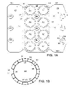
Referring to Figure 1 there is shown a blank 10 comprising a plurality of
panels 12, 14,
16, 18, 20, including a main panel (or lower/engaging panel) 12 for forming a
lower
wall or engaging panel of a carrier 90 (see Figure 2).
A first side panel 14 is hingedly connected to a first side of the main panel
12 by a
hinged connection in the form of a fold line 13. A first top or cover panel 18
is hingedly
connected to the first side panel 14 by a hinged connection in the form of a
fold line
17.
A second side panel 16 is hingedly connected to a second side of the main
panel 12
by a hinged connection in the form of a fold line 15. A second top or cover
panel 20 is
hingedly connected to the second side panel 16 by a hinged connection in the
form of
a fold line 19.
The main panel 12 of the blank 10 includes at least one article retention
structure RT.
The main panel 12 comprises a plurality of article retention structures RT,
specifically
eight article retention structures RT arranged in 2 x 4 matrix or array. Each
of the article
retention structures RT comprises an opening or aperture Al.
The article retention structures RT of the embodiment of Figure 1 takes the
form of a
plurality of teeth or tabs 44, 48 arranged in an annular series about an
aperture Al to
form part of an article receiving opening. In other embodiments the article
retention
structures RT may take a different form, for example but not limited to a pair
of spaced
apart opposing cuts which define a displaceable region forming a cover over an
article
and providing a pair of opposed engaging edges for engaging opposing sides of
an
article below a flange, chime or other projection.
The plurality of teeth 44, 48 are provided by the main panel 12. Each of the
teeth 44,
48 is hingedly connected to the main panel 12, by a hinged connection. The
hinged
- 16 -
CA 03190943 2023- 2- 24
WO 2022/046786
PCT/US2021/047373
connection may be defined by a plurality of cut lines 51, 53. The plurality of
cut lines
51, 53 may be arranged as an annular series of cuts about the apertures Al.
The plurality of cut lines 51, 53 may define or approximate a portion of
circle.
Each of the plurality of teeth 44, 48 comprises an engaging edge opposing a
hinged
edge. The engaging edges are defined by a linear portion of a cut line
defining the first
or second aperture Al. Each engaging edge may define a part of a polygon. The
illustrated embodiment comprises sixteen teeth 44, 48 together defining a
hexadecagon. Each tooth 44, 48 comprises a pair of side edges, the side edges
are
defined by cuts 41, 43, 45, 47 extending radially outward from respective
vertices of
the hexadecagon, that is to say, from a respective vertex between a pair of
adjacent
linear portions of the cut defining the portion of a hexadecagon. The cuts 41,
43, 45,
47 are divergently arranged with respect to each other and define an angle
therebetween, the angle may be about 22.5 .
Each of the plurality of cut lines 51, 53 may be linear in shape.
In alternative embodiments, each of the plurality of cut lines 51, 53 may be
arcuate or
curved. The cut lines 51, 53 may comprise a radius of curvature which is equal
to half
the diameter of the article receiving openings. The cut lines 51, 53 may
comprise a
radius of curvature which is greater than half the diameter of article
receiving openings.
The plurality of teeth 44, 48 may comprise a tab 48 which is disposed
proximate the
hinged connection between the engaging panel 12 and a respective one of the
first
and second side panels 14, 16. The tab 48 may be integral with the engaging
panel
12, that is to say it is free from any cut lines 51, 53 or hinged connection
to the
engaging panel 12. The tab 48 is in sufficiently close proximity to one of the
fold lines
13, 15 hinging the first and second side panels 14, 16 to the engaging panel
12 that
said one of the fold lines 13, 15 effectively serves as a hinged connection to
the tab
48. The tab 48 may be defined by cuts 45, 47 which comprise a `J' or 'C'
shaped cut
proximate said one of the fold lines 13, 15. A portion of the 'J' or 'C'
shaped cut may
lie upon a notional circle defined by the plurality of cut lines 51, 53.
- 17 -
CA 03190943 2023- 2- 24
WO 2022/046786
PCT/US2021/047373
The main panel 12 comprises a handle structure. The handle structure may
comprise
at least one handle opening A2. In the illustrated embodiment, the blank 10
comprises
three handle openings A2. Each handle opening A2 is defined in, or struck
from, a
region of the main panel 12 disposed centrally between four apertures Al
arranged
as two adjacent pairs of apertures Al.
The first and second top panels 18, 20 are arranged to be disposed in at least
partially
overlapping relationship with each other. The overlapping portions of the
first and
second top panels 18, 20 are provided with a locking structure for locking the
first and
second top panels 18, 20. The locking structure cooperates with the handle
openings
in the main panel 12 to secure the first and second top panels 18, 20 to the
main panel
12.
The locking structure comprises at least one receiver in the form of an
opening A3 in
the first top panel 18. The first top panel 18 comprises a plurality of
openings A3, more
specifically three openings A3, although in other embodiments one, two or more
than
three openings may be provided. Each of the openings A3 is arranged to be in
vertical
registry or alignment with a handle opening A2 provided in the main panel 12.
The locking structure comprises at least one locking element L for being
received in
the receiver. The locking element L comprises a tab 80 struck from the second
top
panel 20, the illustrated embodiment comprises three tabs 80 each arranged to
be
engageable with one of the receiver openings A3 and a respective one of the
handle
openings A2. Each tab 80 is hinged to the second top panel 20 by a hinged
connection
81. Each tab 80 may comprise at least one fold line 83, 85. In the illustrated
embodiment, the tab 80 comprises a pair of fold lines 83, 85. The pair of fold
lines 83,
85 may be divergently arranged with respect to each other. Each of the pair of
fold
lines 83, 85 may be non-linear in shape for example but not limited to arcuate
or
curvilinear in shape.
The nonlinear fold lines 83, 85 may encourage the tab 80 to return to a planar
arrangement so as to increase security of the tab 80 within the receiver and
the handle
opening A2.
- 18 -
CA 03190943 2023- 2- 24
WO 2022/046786
PCT/US2021/047373
The tab 80 may be substantially 'arrow head' shaped so as to define a pair of
opposing
shoulders or detents S (see Figure 4) for securely engaging the handle opening
A2
and/or receiver opening A3.
Turning to the construction of the carrier 90 from the blank 10, the blank 10
may be
formed into an assembled carrier 90, as shown in Figure 3.
The blank 10 is applied to a group of articles B. The blank 10 is lowered with
respect
to a group of articles B. Each of the article retention structures RT of the
blank 10 is
aligned with a respective article B in the group. Portions of the articles B
pass through
the main panel 12. The toothed regions of the main panel 12 about each of the
article
retention structures RT may be folded out of the plane of the main panel 12.
Each toothed region of the main panel 12 may be folded about one of the
articles B
received in the respective one of the article retention structures RT. The
main panel
12 may deform about the article B for example but not limited to a shoulder
portion of
the article B, where the article B is a can the shoulder portion may be
provide by the
neck-in, as shown in Figure 2.
The engaging edges of the teeth 44, 48 engage beneath a projection. The
projection
may be located about the neck or chime of the article B (which may provide a
flange)
of an article B. When the article B is a can, the projection may be provided
by a
canner's end seam. In other embodiments it may be provided by a ridge or
undercut
shaping of the article B or by an end closure of the article B for example but
not limited
to a crown cork or closure. In this way, the engaging edges grip or hold the
article B
and prevent or inhibit the article B from unintentionally separating from the
main panel
12.
The blank 10 is folded about fold lines 13, 15 to bring the first side panel
14 into
substantially perpendicular relationship with the main panel 12 and to bring
the second
end panel 16 into substantially perpendicular relationship with the main panel
12.
The blank 10 is folded about fold line 17 to fold the first top panel 18 over
the tops of
the articles B. The blank 10 is folded about fold line 19 to fold the second
top panel 20
- 19 -
CA 03190943 2023- 2- 24
WO 2022/046786
PCT/US2021/047373
over the tops of the articles B and into overlapping relationship with the
first top panel
18 to form a composite top panel 18/20.
The locking tabs 80 are displaced out of the plane of the second top panel 20,
downwardly so as to pass through a respective one of the receiver openings A3.
The
locking tabs 80 are engaged with the main panel 12, passing through a
respective one
of the handle openings A2, best shown in Figure 4. Shoulders of the locking
tab 80
engage with an underside of the main panel 12, the underside being a second
side of
the main panel 12 opposing a first side through which the locking tab 80 was
received.
The fold lines 83, 85 may facilitate folding the locking tab 80 such that it
may pass
through the receiver opening A3 and the handle opening A2.
The locking tab 80 may also provide a cushioning tab improving comfort when
the
package 90 is carried by inserting one or more fingers into the openings in
the
composite top panel 18/20 and the main panel 12.
In some embodiments, not shown, the locking tabs 80 of two adjacently disposed
locking elements L may be arranged so as to be hinged substantially in
opposition to
each other, such that a user may engage a pair of locking elements L
simultaneously
to carry the package 90.
Advantageously, the carrier 90 may be assembled or constructed without use of
glue
or adhesive to secure the panels 12, 14, 16, 18, 20 in an erected condition.
The carrier 90 may beneficially conceal a part of the articles B from view.
The
composite top panel 18/20 may conceal and/or protect a top or upper region of
the
articles B.
Referring now to Figures 5A, 5B, and 50 there is shown an alternative
embodiment of
the present disclosure. In the second illustrated embodiment, like numerals
have,
where possible, been used to denote like parts, albeit with the addition of
the prefix
"100" to indicate that these features belong to the second embodiment. The
alternative
embodiment shares many common features with the embodiment of Figures 1 to 4,
- 20 -
CA 03190943 2023- 2- 24
WO 2022/046786
PCT/US2021/047373
therefore only the differences from the embodiment illustrated in Figures 1 to
4 will be
described in any greater detail.
In the embodiment shown in Figure 5 the main panel 112 comprises alternative
article
retention structures RT1, RT2
The blank 110 comprises four endmost article retention structures RT1 each
comprising a first opening or aperture A4. The blank 110 comprises four medial
or
intermediate article retention structures RT2 each comprising a second opening
or
aperture A5.
The endmost article retention structures RT1 comprises an article receiving
opening
defined in part by the first aperture A4 which is defined in, or struck from,
the main
panel 112.
The intermediate article retention structures RT2 comprises an article
receiving
opening defined in part by the second aperture A5 which is defined in, or
struck from,
the main panel 112.
The endmost article retention structures Rh and the intermediate article
retention
structures RT2 each comprise a plurality of teeth or tabs 144, 146, 148, 148B
disposed
about the first or second aperture Al, A2 respectively.
The plurality of teeth 144, 146, 148, 148B of the endmost article retention
structures
RT1 are interrupted by a first recess or cutaway Cl, best shown in Figure 5C.
The first
recess Cl is provided at a location about the circumference of the first
aperture A4
disposed in closest proximity to an adjacent intermediate article retention
structure
RT2. The first recess Cl extends from the first aperture A4 to towards the
adjacent
intermediate article retention structure RT2.
The plurality of teeth 144, 146, 148, 148B of the endmost article retention
structures
RT1 are interrupted by a second recess or cutaway C3. The second recess C3 is
provided at a location about the circumference of the first aperture A4
disposed in
closest proximity to an adjacent endmost article retention structure RT1. The
second
- 21 -
CA 03190943 2023- 2- 24
WO 2022/046786
PCT/US2021/047373
recess 03 extends from the first aperture A4 to towards the adjacent endmost
article
retention structure RT1.
The endmost article retention structures RT1 comprise a first tab 148 which is
disposed proximate the hinged connection between the engaging panel 112 and a
respective one of the first and second side panels 114, 116. The tab 148 may
be
integral with the engaging panel 112, that is to say it is free from any cut
lines 151,
153 or hinged connection to the engaging panel 112. The tab 148 is in
sufficiently
close proximity to one of the fold lines 113, 115 hinging the first and second
side panels
114, 116 to the engaging panel 112 that said one of the fold lines 113, 115
effectively
serves as a hinged connection to the tab 148. The tab 148 may be defined by
cuts
145, 147 which comprise a `J' or 'C' shaped cut proximate said one of the fold
lines
113, 115. A portion of the `J' or 'C' shaped cut may lie upon a notional
circle defined
by the plurality of cut lines 151, 153.
The endmost article retention structures RT1 comprise a second tab 1488 which
is
disposed proximate a free end edge of the engaging panel 112. The second tab
148
may be defined in part by a second cut lines 149. The second tab 148 may be
defined
by cuts 145, 147 which comprise a `J' or 'C' shaped cut proximate said one of
the fold
lines 113, 115. The second cut 149 is disposed between cuts 145, 147. A
portion of
the `J' or 'C' shaped cut may lie upon a notional circle defined by the
plurality of cut
lines 151, 153. The second cut 149 may be longer in length than the cut lines
151,
153.
The second tab 148B is disposed opposite the first recess Cl. The tab 148 is
disposed
opposite the second recess 03.
The intermediate article retention structures RT2 are substantially similar in
construction to the endmost article retention structures RT1, albeit the
second tab
148B has been replaced with a third recess or cutaway 02. The third recess 02
is
provided at a location about the circumference of the second aperture A2
disposed in
closest proximity to an adjacent endmost article retention structure RT1. The
third
recess 02 extends from the second aperture A5 towards the adjacent endmost
article
- 22 -
CA 03190943 2023- 2- 24
WO 2022/046786
PCT/US2021/047373
retention structure RT1. The third recess 02 is disposed opposite the first
recess Cl,
the second recess C3 is oriented perpendicular to the first and third recesses
Cl, C2.
Referring now to Figures 6 to 11 there is shown a further alternative
embodiment of
the present disclosure. In the third illustrated embodiment, like numerals
have, where
possible, been used to denote like parts, albeit with the addition of the
prefix "200" to
indicate that these features belong to the third embodiment. The alternative
embodiment shares many common features with the embodiments of Figures 1 to 5,
therefore only the differences from the embodiment illustrated in Figures 1 to
5 will be
described in any greater detail.
Figure 6 shows a first blank 210A comprising a plurality of panels 212, 214A,
214B,
216A, 216B, 218, 220, including a main panel (or lower/engaging panel) 212 for
forming a top wall or engaging panel of a carrier 290 (see Figure 8).
A first side panel 218 is hingedly connected to a first side of the main panel
212 by a
hinged connection in the form of a fold line 217.
A second side panel 220 is hingedly connected to a second side of the main
panel
212 by a hinged connection in the form of a fold line 219.
The first blank 210A comprises a first end structure. The first end structure
comprises
a first upper end panel 214A hingedly connected to a first end of the main
panel 212
by a hinged connection in the form of a fold line 213A. A first lower end
panel 214B is
hingedly connected to the first upper end panel 214A by a hinged connection in
the
form of a fold line 213B.
The first end structure comprises a first corner panel 260A hingedly connected
to a
first end of the first side panel 218 by a hinged connection in the form of a
fold line
261A. A second corner panel 260B is hingedly connected to a first end of the
second
side panel 220 by a hinged connection in the form of a fold line 261B.
The first end structure comprises a first securing panel 264A hingedly
connected to
the first corner panel 260A by a hinged connection in the form of a fold line
263A. A
- 23 -
CA 03190943 2023- 2- 24
WO 2022/046786
PCT/US2021/047373
second securing panel 264B is hingedly connected to the second corner panel
260B
by a hinged connection in the form of a fold line 263B.
A first web panel 268A is hingedly connected at one end to the first securing
panel
264A by a hinged connection in the form of a fold line 269A and is hingedly
connected
at a second end to the first upper end panel 214A by a hinged connection in
the form
of a fold line 271A.
A second web panel 268B is hingedly connected at one end to the second
securing
panel 264B by a hinged connection in the form of a fold line 269B and is
hingedly
connected at a second end to the first upper end panel 214A by a hinged
connection
in the form of a fold line 271B.
The first blank 210A comprises a second end structure. The second end
structure
comprises a second upper end panel 216A hingedly connected to a second end of
the
main panel 212 by a hinged connection in the form of a fold line 215A. A
second lower
end panel 216B is hingedly connected to the second upper end panel 216A by a
hinged connection in the form of a fold line 215B.
The second end structure comprises a third corner panel 262A hingedly
connected to
a second end of the first side panel 218 by a hinged connection in the form of
a fold
line 265A. A fourth corner panel 262B is hingedly connected to a second end of
the
second side panel 220 by a hinged connection in the form of a fold line 265B.
The first end structure comprises a third securing panel 266A hingedly
connected to
the third corner panel 262A by a hinged connection in the form of a fold line
267A. A
fourth securing panel 266B is hingedly connected to the fourth corner panel
262B by
a hinged connection in the form of a fold line 267B.
A third web panel 270A is hingedly connected at one end to the third securing
panel
266A by a hinged connection in the form of a fold line 273A and is hingedly
connected
at a second end to the second upper end panel 216A by a hinged connection in
the
form of a fold line 275A.
- 24 -
CA 03190943 2023- 2- 24
WO 2022/046786
PCT/US2021/047373
A fourth web panel 270B is hingedly connected at one end to the fourth
securing panel
266B by a hinged connection in the form of a fold line 273B and is hingedly
connected
at a second end to the second upper end panel 216A by a hinged connection in
the
form of a fold line 275B.
It will be appreciated that the first side panel 218, the first corner panel
260A, the first
securing panel 264A, the third corner panel 262A, and the third securing panel
266A
form a first strap 264A/260A/218/262A/266A along a first side of the main
panel 212.
The second side panel 220, the second corner panel 260B, the second securing
panel
264B, the fourth corner panel 262B, and the fourth securing panel 266B form a
second
strap 264B/260B/220/262B/266B along a second side of the main panel 212.
The first blank 210A comprises first flap 272 hingedly connected to the first
lower end
panel 214B by a hinged connection. The hinged connection is defined, at least
in part,
by a cut line V1. Cut line V1 defines a tab P1 extending from an outer or
lower edge
of the first lower end panel 214B. The cut line V1 forms a receiver, in the
form of an
opening, slot or slit, for receiving a locking tab or detent Dl. Each of the
first and
second securing panels 264A, 264B comprises a locking tab or detent D1
extending
from a lower edge thereof.
The first flap 272 may comprise a pair of wing portions 274A, 274B hingedly
connected
by a respective fold line 277A, 277B to a central portion of the first flap
272. The fold
lines 277A, 277B may be divergently arranged with respect to each other, the
fold lines
277A, 277B diverge towards the first lower end panel 214B.
Each of the first and second securing panels 264A, 264B comprises a cutaway in
the
form of an aperture A9. Each aperture A9 forms a second receiver for receiving
a
respective second locking tab or detent D2. The first upper end panel 214A
comprises
a pair of cut lines 201, each of which is substantially "U" shaped, each cut
line 201
defines a respective detent D2.
The first blank 210A comprises second flap 276 hingedly connected to the
second
lower end panel 216B by a hinged connection. The hinged connection is defined,
at
least in part, by a cut line V2. Outline V2 defines a second tab P2 extending
from an
- 25 -
CA 03190943 2023- 2- 24
WO 2022/046786
PCT/US2021/047373
outer or lower edge of the second lower end panel 216B. The cut line V2 forms
a
receiver, in the form of an opening, slot or slit, for receiving a locking tab
or detent D2.
Each of the third and fourth securing panels 266A, 266B comprises a locking
tab or
detent D2 extending from a lower edge thereof.
The second flap 276 may comprise a pair of wing portions 278A, 278B hingedly
connected by a respective fold line 278A, 278B to a central portion of the
second flap
276. The fold lines 279A, 279B may be divergently arranged with respect to
each other,
the fold lines 279A, 279B diverge towards the second lower end panel 216B.
Each of the third and fourth securing panels 266A, 266B comprises a cutaway in
the
form of an aperture A9. Each aperture A5 forms a second receiver for receiving
a
respective second locking tab or detent D2. The second upper end panel 216A
comprises a pair of cut lines 201, each of which is substantially "U" shaped,
each cut
line 201 defines a respective detent D2.
The main panel 212 comprises at least one article retention structure RT1,
RT2. The
main panel 212 comprises a plurality of article retention structures RT1, RT2,
specifically eight article retention structures RT1, RT2 arranged in 2 x 4
matrix or array.
Each of the article retention structures RT1, RT2 comprises an opening or
aperture
A7, A8.
The article retention structures RT1, RT2 of the illustrated embodiment take
the form
of a plurality of teeth or tabs 244, 246 arranged in an annular series about
an aperture
A7, A8 to form part of an article receiving opening.
The first blank 210A comprises four first or endmost article retention
structures RT1
each comprising a first opening or aperture A7. The first blank 210A comprises
four
second, medial or intermediate article retention structures RT2 each
comprising a
second opening or aperture A8.
The endmost article retention structures RT1 comprises an article receiving
opening
defined in part by the first aperture A7 which is defined in, or struck from,
the main
panel 212.
- 26 -
CA 03190943 2023- 2- 24
WO 2022/046786
PCT/US2021/047373
The intermediate article retention structures RT2 comprises an article
receiving
opening defined in part by the second aperture A8 which is defined in, or
struck from,
the main panel 212.
The endmost article retention structures RT1 and the intermediate article
retention
structures RT2 each comprise a plurality of teeth or tabs 244, 246 disposed
about the
first or second aperture A7, A8 respectively.
The plurality of teeth 244, 246 are provided by the main panel 212. Each of
the teeth
244, 246 is hingedly connected to the main panel 212, by a hinged connection.
The
hinged connection may be defined by a plurality of cut lines 251, 253. The
plurality of
cut lines 251, 253 may be arranged as an annular series of cuts about the
first or
second apertures A7, A8. The plurality of cut lines 251, 253may define or
approximate
a portion of circle.
Each of the first article retention structures RT1 is substantially similar in
construction
and will therefore be described in detail with reference to a first one of the
first article
retention structures RT1 located adjacent to a first end of the first blank
210A as shown
in Figure 6.
The first article retention structure RT1 comprises a plurality of first or
full teeth 244
disposed about the aperture Al. Each of the plurality of first teeth 244
comprises an
engaging edge El opposing a hinged edge. The engaging edges El are defined by
a
linear portion of a cut line defining the aperture A7. Each engaging edge El
defines a
part of a hexadecagon. The illustrated embodiment comprises six first teeth
244
together defining a portion of a hexadecagon. Each tooth 244 comprises a pair
of side
edges, the side edges are defined by cut lines 241, 243 extending radially
outward
from respective vertices of the hexadecagon. That is to say from a respective
vertex
between a pair of adjacent linear portions of the cut line defining the
aperture A7. The
cut lines 241, 243 are divergently arranged with respect to each other and
define an
angle therebetween, the angle may be about 22.5 .
- 27 -
CA 03190943 2023- 2- 24
WO 2022/046786
PCT/US2021/047373
The first article retention structure RT1 comprises a plurality of first
circumferential cut
lines 251. Each of the plurality of first circumferential cut lines 251 is
aligned with one
of the radial cut lines 241, 243 such that said one of the radial cut lines
241, 243 or a
notional extension thereof bisects a respective one of the plurality of first
circumferential cut lines 251.
Each of the plurality of first circumferential cut lines 251 is spaced apart
from said one
of the radial cut lines 241, 243 bisecting it so as to define a connecting
nick or bridge
portion between a pair of adjacently disposed teeth 244, 246.
Each of the plurality of first circumferential cut lines 251 may be linear in
shape.
The first article retention structure RT1 comprises a plurality of second
circumferential
cut lines 253. Each of the plurality of second circumferential cut lines 253
is disposed
between a pair of the plurality of first circumferential cut lines 251 and is
spaced apart
therefrom so as to define a pair of connecting nick or bridge portions between
each
tooth 244, 246 and the main panel 212. The pair of connecting nick or bridge
portions
provide a hinged or foldable connection between each tooth 244, 246 and the
main
panel 212.
Each of the plurality of second circumferential cut lines 253 may be linear in
shape.
In alternative embodiments, each of the plurality of first circumferential cut
lines 251
may be arcuate or curved. The first circumferential cut lines 251 may comprise
a radius
of curvature which is equal to half the diameter of the article receiving
openings. The
first circumferential cut lines 251 may comprise a radius of curvature which
is greater
than half the diameter of the apertures A7.
In alternative embodiments, each of the plurality of second circumferential
cut lines
253 may be arcuate or curved. The second circumferential cut lines 253 may
comprise
a radius of curvature which is equal to half the diameter of the article
receiving
openings. The second circumferential cut lines 253 may comprise a radius of
curvature
which is greater than half the diameter of the aperture A7.
- 28 -
CA 03190943 2023- 2- 24
WO 2022/046786
PCT/US2021/047373
The first and second circumferential cut lines 251, 253 when linear may be
considered
to define portions of a circle of infinite radius.
In the illustrated embodiment, the radius of curvature of each of the
plurality of second
circumferential cut lines 253 is equal to the radius of curvature of each of
the plurality
of first circumferential cut lines 251 however in other embodiments it may be
different.
Optionally, the plurality of teeth 244, 246 is interrupted by a first recess
or cutaway 02.
The first recess 02 lies upon a first notional line y-y. First notional line y-
y extends
radially from the centre C of the apertures A7, A8 and passes through the
centre of
the first recess C2. The first notional line y-y may extend across the grain
of the first
blank 210A. The first notional line y-y is oriented perpendicularly with
respect to the
grain direction. The first notional line y-y extends longitudinally of the
first blank 210A.
Optionally, the plurality of teeth 244, 246 is interrupted by a second recess
or cutaway
03. The second recess 03 lies upon a second notional line x-x. Second notional
line
x-x extends radially from the centre C of the apertures A7, A8 and passes
through the
centre of the second recess C3. The second notional line x-x may extend along
the
grain of the first blank 210A. The notional line x-x is oriented parallel with
respect to
the grain direction. The notional line x-x extends transversely, or laterally,
of the first
blank 210A.
Optionally, the plurality of teeth 244, 246 is interrupted by a third recess
or cutaway
C4. The third recess C4 lies upon the second notional line x-x.
The first recess 02 is dimensioned so as to occupy a first arc defined by a
first minor
sector. The first minor sector is defined in part by a first sector notional
line extending
radially from the centre C of the notional circle and passing through a side
edge of a
first partial tooth 246 disposed adjacent a first side of the first recess 02
and in part by
a second sector notional line extending radially from the centre C of the
notional circle
and passing through a side edge of a second partial tooth 246 disposed
adjacent a
second, opposing, side of the first recess C2. The first and second sector
notional lines
define a second angle therebetween. The second angle may be in the range 35
to
500, and may be around 45 .
- 29 -
CA 03190943 2023- 2- 24
WO 2022/046786
PCT/US2021/047373
The second recess C3 is dimensioned so as to occupy a second arc defined by a
second minor sector. The second minor sector is defined in part by a third
sector
notional line extending radially from the centre C of the notional circle and
passing
through a side edge of a third partial tooth 246 disposed adjacent a first
side of the
second recess 03 and in part by a fourth sector notional line extending
radially from
the centre C of the notional circle and passing through a side edge of a
fourth partial
tooth 246 disposed adjacent a second, opposing, side of the second recess 03.
The
third and fourth sector notional lines define a third angle therebetween. The
third angle
may be in the range 35 to 500, and may be around 45 .
The third recess 04 is dimensioned so as to occupy a third arc defined by a
third minor
sector. The third minor sector is defined in part by a fifth sector notional
line extending
radially from the centre C of the notional circle and passing through a side
edge of a
fifth partial tooth 246 disposed adjacent a first side of the third recess C4
and in part
by a sixth sector notional line extending radially from the centre C of the
notional circle
and passing through a side edge of a sixth partial tooth 246 disposed adjacent
a
second, opposing, side of the third recess 04. The third and fourth sector
notional lines
define a third angle therebetween. The third angle may be in the range 35 to
500, and
may be around 45 .
The second and third recesses 03, 04 are diametrically opposed to each other.
The third and fifth sector notional lines define a major or first toothed
sector, the first
toothed sector defines a fourth arc; the fourth arc is occupied by teeth 244,
246. That
is to say teeth 244, 246 are disposed about the third arc, in a perimeter
region of the
first aperture A7.
The first and fourth sector notional lines define a fourth minor sector or
second toothed
sector, the second toothed sector defines a fifth arc; the fifth arc is
occupied by teeth
244, 246. That is to say teeth 244, 246 are disposed about the fifth arc, in a
perimeter
region of the first aperture A7.
- 30 -
CA 03190943 2023- 2- 24
WO 2022/046786
PCT/US2021/047373
The second and sixth sector notional lines define a fifth minor sector or
third toothed
sector, the third toothed sector defines a sixth arc; the sixth arc is
occupied by teeth
244, 246. That is to say teeth 244, 246 are disposed about the sixth arc, in a
perimeter
region of the first aperture A7.
The first article retention structure RT1 comprises a first engaging tab 248
opposing
the first recess C2.
The first engaging tab 248 is disposed proximate the first or second upper end
panel
214A, 216A. The first engaging tab 248 is integral with the main panel 212,
that is to
say the first and second circumferential cut lines 251, 253 have been omitted.
The first
engaging tab 248 is proximate to the fold line 213A, 215A hinging the main
panel to
the respective upper end panel 214A, 216A.
Each of the second article retention structures RT2 is substantially similar
in
construction and will therefore be described in detail with reference to a
first one of the
second article retention structures RT2 located adjacent to the first one of
the first
article retention structures RT1 as shown in Figure 10.
The second article retention structure RT2 comprises an article receiving
opening
defined in part by a second aperture A8.
The second article retention structure RT2 comprises a plurality of teeth 244,
246
disposed about the second aperture AS. The plurality of teeth 244, 246, or at
least free
edges thereof, may define, or approximate, a second notional circle.
The plurality of teeth 244, 246 are hinged to the main panel 212 by a fold
line. The fold
line may be defined by a plurality of cut lines 251, 253. The plurality of cut
lines 251,
253 may define or approximate a circle.
The second article retention structure RT2 is substantially similar in
construction to the
first article retention structure RT1, albeit the first engaging tab 248 has
been replaced
with a fourth recess Cl. The first and fourth recesses 02, Cl are
diametrically opposed
to each other.
- 31 -
CA 03190943 2023- 2- 24
WO 2022/046786
PCT/US2021/047373
The second and third recesses 03, 04 are diametrically opposed to each other.
The second and third recesses 03, 04 are oriented or disposed substantially
orthogonally to the first and fourth recesses 02, Cl.
The centre of the first and fourth recesses 02, Cl of the second article
retention
structure RT2 are collinear with the centre of the first recess 02 of the
first article
retention structure RT1.
The fourth recess Cl of the second article retention structure RT2 is disposed
proximate to the first recess Cl of the first article retention structure RT1
and is
oriented in opposition thereto.
Each of the second recesses C3 of the second article retention structures RT2
is
disposed proximate to a second recess 03 of an adjacently disposed second
article
retention structures RT2, and is oriented in opposition thereto.
Each of the second recesses 03 of the first article retention structures RT1
is disposed
proximate to a second recess C3 of an adjacently disposed first article
retention
structures RT1, and is oriented in opposition thereto.
The grain of the material forming the first blank 210A may be arranged to be
tangential
to the centre of the first and fourth recesses C2, Cl of the second article
retention
structure RT2. The grain of the material forming the first blank 210A may be
arranged
to be tangential to the centre of the first recess 02 of the first article
retention structure
RT1. In this way in order for a tear to propagate between the first aperture
A7 and the
second aperture A8 the tear must propagate across the grain of the first blank
210A.
In this way the first blank 210A is arranged to provide maximum resistance to
tear
propagation between the first and second apertures A7, A8.
Removal of the teeth 244, by providing recesses Cl, C2, C3, at locations where
two
adjacent apertures A7, A8 are disposed in close proximity, may be
advantageous, for
example when packaging articles B of the sleek or slim design, and has been
found
- 32 -
CA 03190943 2023- 2- 24
WO 2022/046786
PCT/US2021/047373
to reduce the likelihood of tear propagation. Slim design articles B are those
which are
substantially of the same diameter over their entire height. In some
embodiments the
variation in diameter between a top closure of the article B and the main body
of the
article B may be less than 7mm, may be less than 5mm and optionally is less
than
4mm. This beneficial advantage may be a result of removal of the radial cut
lines 241,
246 in regions of the first blank 210A where the apertures A7, A8 are in close
proximity.
The main panel 212 comprises a handle structure. The handle structure may
comprise
at least one handle opening A2. In the illustrated embodiment, the blank 210A
comprises two handle openings A2. Each handle opening A2 is defined in or
struck
from a region of the main panel 212 disposed centrally between four aperture
A7, A8
arranged as two adjacent pairs of apertures A7, A8. A first one of the handle
openings
A2 is disposed between a first pair of endmost apertures A7 and an adjacent
pair of
intermediate apertures A8. A second one of the handle openings A2 is disposed
between a second pair of endmost apertures A7 and an adjacent pair of
intermediate
apertures A8. The second pair of endmost apertures A7 being disposed at an
opposing end of the main panel 212 to the first pair of endmost apertures A7.
The end structures are folded to secure the first and second side panels 218,
220
about sides of a group of articles B. The blank 210A can be applied to the
group of
articles B in a flat form and folded thereabout.
The main panel 212 is lowered with respect to a group of articles B. The first
and
second side panels 218, 220 are folded about opposing sides of the group of
articles
B. The corner panels 260A, 260B, 262A, 262B are folded about the corners of
the
group of articles B and the securing panels 264A, 264B, 266A, 266B are folded
about
ends of the group of articles B.
The first and second upper end panels 214A, 216A are folded downwards about a
respective end of the group of articles B. The first and second lower end
panels 214B,
116B are folded upwardly with respect to the first and second upper end panels
214A,
216A such that the detents D2 can be inserted into the apertures A9. The first
and
second lower end panels 214B, 216B are folded downwardly to return to a
- 33 -
CA 03190943 2023- 2- 24
WO 2022/046786
PCT/US2021/047373
substantially coplanar relationship with the respective one of the first and
second
upper end panels 214A, 216A to which they are hinged.
The first and second flaps 272, 276 are folded internally, the wing portions
274A, 274B,
278A, 278B are folded with respect to the central portion so as to pass the
side walls
of adjacently disposed articles B.
The cut lines V1, V2 form an opening in which the locking tab D1 of each
securing
panel 264A, 264B, 266A, 266B is received.
The wing portions 274A, 274B, 278A, 278B are folded into coplanar relationship
with
the central portion of the respective tab 272, 276; in this way the tabs 272,
276 are
held in position by the adjacently disposed articles B.
The tabs 272, 276 are held in the folded condition by the articles B and thus
inhibit
disengagement of the locking tabs D1 from the receiver.
The tabs 272, 276 in the folded condition are in face to face relationship
with the
portions of the detents D2 received in the apertures A9; and may inhibit
disengagement of detents D2 from the apertures A9.
The tabs P1, P2 may conceal or protect the locking tabs D1 so as to improve
security
of the locking tabs D1 in the receiver.
An article carrier 292 formed from the first blank 210A is shown in Figure 8.
The third illustrated embodiment comprises a second blank 210B for forming a
top
cover. Second blank 210B comprises a cover panel 254 having opposed marginal
regions 254A, 254B.
A first marginal region is defined at least in part by a first fold line 213A.
A second
marginal region 213B is defined by a second fold line 257B.
- 34 -
CA 03190943 2023- 2- 24
WO 2022/046786
PCT/US2021/047373
The first fold line 213A is interrupted by a plurality of article receiving
structures in the
form of slits or cut lines 256A. The slits 256A may be curvilinear in shape
and may be
substantially `U' shaped.
The second fold line 213B is interrupted by a plurality of article receiving
structures in
the form of slits or cut lines 256B. The slits 256B may be curvilinear in
shape and may
be substantially 'Li' shaped.
When the first and second marginal regions 254A, 2546 are folded about the
first and
second fold lines 257A, 257B respectively the slits 256A, 256B open to form an
article
receiving slot or aperture. An edge of the first and second marginal regions
254A,
254B defined by the slits 256A, 256B provides an engaging edge which engage
below
a flange, chime or other projection or undercut provided by an article B
received in the
article receiving slot or aperture formed when the marginal regions 254A, 254B
are
folded with respect to a medial portion of the cover panel 254.
The cover panel 254 comprises at least one with a locking structure for
locking the
cover panel 254 to the main panel 212. A locking element L cooperates with the
handle
openings A2 in the main panel 212 to secure the cover panel 254 thereto.
The handle openings A2 in the main panel 212 form receivers. The illustrated
embodiment comprises two receivers.
The locking structure comprises at least one locking element L for being
received in
the receiver. The locking element L comprises a tab 280 struck from the cover
panel
254, the illustrated embodiment comprises two tabs 280 each arranged to be
engageable with one of the handle openings A2. Each tab 280 is hinged to the
cover
panel 254 by a hinged connection 281. Each tab 280 may comprise at least one
fold
line 283, 285. In the illustrated embodiment, the tab 280 comprises a pair of
fold lines
283, 285. The pair of fold lines 283, 285 may be divergently arranged with
respect to
each other. Each of the pair of fold lines 283, 285 may be non-linear in shape
for
example but not limited to arcuate or curvilinear in shape.
- 35 -
CA 03190943 2023- 2- 24
WO 2022/046786
PCT/US2021/047373
The nonlinear fold lines 283, 285 may encourage the tab 280 to return to a
planar
arrangement to increase security of the tab 280 when folded to be received
within the
receiver.
The tab 280 may be substantially 'arrow head' shaped so as to define a pair of
opposing shoulders or detents S (see Figure 11) for securely engaging the
handle
opening A2.
In order to form the package 290 illustrated in Figure 9 the second blank 210B
is
lowered over the article carrier 292 shown in Figure 8. The marginal regions
254A,
254B are folded downwardly about shoulders or necks of the articles B, the
slits 256A,
256B open and receive a flange or lip of a respective article B as shown in
Figure 9.
The cover panel 254 is secured to the article carrier 292 by engaging the
locking
elements L in the receiver provided by the handle opening A2 in the main panel
212,
as shown in Figure 10. Figure 11 shows enlarged view of the tab 280 engaging
the
main panel 212 disposed therebelow. The tab 280 extends across a gap or void
between the cover panel 254 and the main panel 212. The articles B maintain
the
cover panel 254 in a spaced apart relationship from the main panel 212. The
upper
portions of the articles B which pass through the main panel 212 prevent, or
at least
inhibit, the cover panel 254 from adopting a face contacting relationship with
the main
panel 212.
Referring now to Figures 12A to 20 there are shown further alternative
embodiments
of the present disclosure. In the fourth and fifth illustrated embodiments,
like numerals
have, where possible, been used to denote like parts, albeit with the addition
of the
prefix "300", "400" to indicate that these features belong to the fourth and
fifth
embodiments. The alternative embodiments share many common features with the
embodiments of Figures 1 to 11, therefore only the differences from the
embodiments
illustrated in Figures 1 to 11 will be described in any greater detail.
Referring to Figure 12A there is shown a blank 310 comprising a plurality of
panels
312, 314, 316, 318, 320, including a main panel (or lower/engaging panel) 312
for
forming a lower wall or engaging panel of a carrier 390 (see Figure 18).
- 36 -
CA 03190943 2023- 2- 24
WO 2022/046786
PCT/US2021/047373
A first side panel 314 is hingedly connected to a first side of the main panel
312 by a
hinged connection in the form of a fold line 313. A first top or cover panel
318 is
hingedly connected to the first side panel 314 by a hinged connection in the
form of a
fold line 317.
A second side panel 316 is hingedly connected to a second side of the main
panel
312 by a hinged connection in the form of a fold line 315. A second top or
cover panel
320 is hingedly connected to the second side panel 316 by a hinged connection
in the
form of a fold line 319.
The main panel 312 of the blank 310 includes at least one article retention
structure
RT1, RT2. The main panel 312 comprises a plurality of article retention
structures RT1,
RT2, specifically eight article retention structures RT1, RT2 arranged in 2 x
4 matrix
or array. Each of the article retention structures RT1, RT2 comprises an
opening or
aperture A4, A5. The article retention structures RT1, RT2 are substantially
similar to
those shown in Figures 5A, 5B and 50 and will not be described in further
detail.
The main panel 312 comprises a handle structure. The handle structure may
comprise
at least one handle opening A2. In the illustrated embodiment, the blank 310
comprises three handle openings A2. Each handle opening A2 is defined in or
struck
from a region of the main panel 312 disposed centrally between four apertures
A4, A5
arranged as two adjacent pairs of apertures A4, A5.
The first and second top panels 318, 320 are arranged to be disposed in at
least
partially overlapping relationship with each other. The overlapping portions
of the first
and second top panels 318, 320 are provided with a locking structure for
locking the
first and second top panels 318, 320. The locking structure cooperates with
the handle
openings in the main panel 312 to secure the first and second top panels 318,
320 to
the main panel 312.
The locking structure comprises at least one receiver RC in the form of an
opening in
the first top panel 318. The first top panel 318 comprises a plurality of
openings, more
specifically three openings, although in other embodiments one, two or more
than
- 37 -
CA 03190943 2023- 2- 24
WO 2022/046786
PCT/US2021/047373
three openings may be provided. Each of the openings is arranged to be in
vertical
registry or alignment with a handle opening A2 provided in the main panel 312.
The
openings may be defined by at least one tab 392, 394, 396 (also referred to
herein as
female tabs or receiver tabs). In the illustrated embodiment, the openings are
defined
by three tabs 392, 394, 396. The openings may be substantially square or
diamond
shaped, In the illustrated embodiment, the corners of the opening are rounded
or
filleted. A first tab 396 is hinged to the first top panel 318 by a first
hinged connection
in the form of a first fold line 391. A second tab 392 is hinged to the first
top panel 318
by a second hinged connection in the form of a second fold line 393. The
second tab
392 is hinged to the first top panel 318 in opposition to the first tab 396.
The first tab
396 is separated in part from the second tab 392 by a first severance line or
cut line
397 and in part by a third tab 394. The third tab 394 is defined by a second
severance
line or cut line 399. The second cut line 399 is substantially `U' shaped. The
third tab
394 is hinged to the first top panel 318 by a third hinged connection in the
form of a
third fold line 395. The third hinged connection is disposed adjacent to the
first and/or
second hinged connection, and may be substantially orthogonal thereto. The
third tab
394 defines a cutout or recess in each of the first and second tabs 396, 392.
The cutout
or recess is struck from a free end edge opposing the first and second hinged
connections respectively.
The locking structure comprises at least one locking element L for being
received in
the receiver RC. The locking element L comprises a tab 380 struck from the
second
top panel 320, the illustrated embodiment comprises three tabs 380 each
arranged to
be engageable with one of the receiver openings and a respective one of the
handle
openings A2. Each tab 380 is hinged to the second top panel 320 by a hinged
connection 381. Each tab 380 may comprise at least one fold line substantially
similar
to those of the embodiment of Figure 1A.
The tab 380 may be substantially 'arrow head' shaped so as to define a pair of
opposing shoulders or detents S (see Figure 19) for securely engaging the
handle
opening A2 and/or receiver RC.
The first top panel 318, second top panel 320, first and second side panels
314, 316
and main panel 312 form a tubular structure. Each end of the tubular structure
is closed
- 38 -
CA 03190943 2023- 2- 24
WO 2022/046786
PCT/US2021/047373
by an end closure structure. A first end closure structure comprises a first
end panel
324 hingedly connected to a first end of the main panel 312 by a hinged
connection in
the form of a fold line 325. A first top end flap 326 is hingedly connected to
the first
end panel 324 by a hinged connection in the form of a fold line 327.
A first anchor flap 322A is hingedly connected to a first end of the first
side panel 318
by a hinged connection in the form of a fold line 323A. The first anchor flap
322A is
hingedly connected to the first top end flap 326 by a pair of hinged panels
328A, 330A.
The pair of hinged panels 328A, 330A form a gusset. A first connecting panel
328A is
hingedly connected to the first anchor flap 322A by a hinged connection in the
form of
a fold line. A second connecting panel 330A is hingedly connected to the first
connecting panel 328A by a hinged connection in the form of a fold line. The
second
connecting panel 330A is hingedly connected to the first top end flap 326 by a
hinged
connection in the form of a fold line.
A second anchor flap 322B is hingedly connected to a first end of the second
side
panel 320 by a hinged connection in the form of a fold line 323B. The second
anchor
flap 322B is hingedly connected to the first top end flap 326 by a pair of
hinged panels
328B, 330B forming a second gusset. A third connecting panel 328B is hingedly
connected to the second anchor flap 322B by a hinged connection in the form of
a fold
line. A fourth connecting panel 330B is hingedly connected to the third
connecting
panel 328B by a hinged connection in the form of a fold line. The fourth
connecting
panel 330B is hingedly connected to the first top end flap 326 by a hinged
connection
in the form of a fold line.
The first end panel 324 is separated from each of the first and second anchor
flaps
322A, 322B by an aperture A10. The apertures Al 0 separate each of the pair of
hinged
panels 328A/330A, 328B/330B from the respective one of the first and second
side
panels 314, 316.
A second end closure structure comprises a second end panel 334 hingedly
connected to a second end of the main panel 312 by a hinged connection in the
form
of a fold line 335. A second top end flap 336 is hingedly connected to the
second end
panel 334 by a hinged connection in the form of a fold line 337.
- 39 -
CA 03190943 2023- 2- 24
WO 2022/046786
PCT/US2021/047373
A third anchor flap 332A is hingedly connected to a second end of the first
side panel
318 by a hinged connection in the form of a fold line 333A. The third anchor
flap 332A
is hingedly connected to the second top end flap 336 by a pair of hinged
panels 338A,
340A forming a third gusset. A fifth connecting panel 338A is hingedly
connected to
the third anchor flap 332A by a hinged connection in the form of a fold line.
A sixth
connecting panel 340A is hingedly connected to the fifth connecting panel 338A
by a
hinged connection in the form of a fold line. The sixth connecting panel 340A
is
hingedly connected to the second top end flap 336 by a hinged connection in
the form
of a fold line.
A fourth anchor flap 332B is hingedly connected to a second end of the second
side
panel 320 by a hinged connection in the form of a fold line 333B. The fourth
anchor
flap 332B is hingedly connected to the second top end flap 336 by a pair of
hinged
panels 338B, 340B forming a fourth gusset. A seventh connecting panel 338B is
hingedly connected to the fourth anchor flap 332B by a hinged connection in
the form
of a fold line 339B (see Figure 12B). An eighth connecting panel 340B is
hingedly
connected to the seventh connecting panel 338B by a hinged connection in the
form
of a fold line 355B. The eighth connecting panel 340B is hingedly connected to
the
second top end flap 336 by a hinged connection in the form of a fold line
359B.
The second end panel 334 is separated from each of the third and fourth anchor
flaps
332A, 332B by an aperture A10. The apertures Al 0 separate each of the pair of
hinged
panels 338A/340A, 338B/340B from the respective one of the first and second
side
panels 314, 316.
Turning to the construction of the carrier 390 from the blank 310, the blank
310 may
be formed into an assembled carrier 390, as shown in Figure 18.
The blank 310 is applied to a group of articles B, as shown in Figure 13. The
blank
310 is lowered with respect to a group of articles B. Each of the article
retention
structures RT1, RT2 of the blank 310 is aligned with a respective article B in
the group.
Portions of the articles B pass through the main panel 312. The toothed
regions of the
- 40 -
CA 03190943 2023- 2- 24
WO 2022/046786
PCT/US2021/047373
main panel 312 about each of the article retention structures RT1, RT2 may be
folded
out of the plane of the main panel 312.
Each toothed region of the main panel 312 may be folded about one of the
articles B
received in the respective one of the article retention structures RT1, RT2.
The main
panel 312 may deform about the article B for example but not limited to a
shoulder
portion of the article B, where the article B is a can the shoulder portion
may be provide
by the neck-in, as shown in Figure 13.
The blank 310 may be partially folded about fold lines 313, 315 to bring the
first and
second side panels 314, 316 into non-coplanar relationship with the main panel
312,
as shown in Figure 13.
The blank 310 is folded about fold lines 323A, 323B, 333A, 333B to fold the
first,
second, third and fourth anchor flaps 322A, 322B, 332A, 332B into
substantially face
to face relationship with the first or second side panels 314, 316 to which
they are
hinged.
The blank 310 is folded about fold lines 325, 335 to fold the first and second
end panels
324, 334 into substantially at least perpendicular relationship with the main
panel 312.
In some embodiments the first and second end panels 324, 334 may be folded
through
an angle greater than 90 so as to be inclined.
The blank 310 is folded about fold lines 327, 337 to fold the first and second
top end
flaps 326, 336 with respect to the respective one of the first and second end
panels
324, 334 to which they are hinged.
The first and second top end flaps 326, 336 may be folded over an upper end of
an
article B or articles B disposed adjacent to the first and second ends of the
main panel
312.
The first and second top end flaps 326, 336 may be folded to be substantially
parallel
to the main panel 312.
- 41 -
CA 03190943 2023- 2- 24
WO 2022/046786
PCT/US2021/047373
The first and second end panels 324, 334 and first and second top end flaps
326, 336
may be folded automatically in response to folding the first, second, third
and fourth
anchor flaps 322A, 322B, 332A, 332B into substantially face contacting
relationship
with the respective one of the first and second side panels 314, 316.
The blank 310 is folded about fold lines 313, 315 to bring the first and
second side
panels 314, 316 into substantially perpendicular relationship with the main
panel 312.
The blank 310 is folded about fold line 317 to fold the first top panel 318
over the tops
of the articles B. The blank 310 is folded about fold line 319 to fold the
second top
panel 320 over the tops of the articles B and into overlapping relationship
with the first
top panel 318 to form a composite top panel 318/320.
The locking tabs 380 are displaced out of the plane of the second top panel
320,
downwardly so as to pass through a respective one of the receiver openings.
The
receiver tabs 392, 394, 396 displaced out of the plane of the first top panel
318 as a
consequence.
The locking tabs 380 are engaged with the first and second receiver tabs 396,
392,
best shown in Figure 19. Shoulders S of the locking tab 380 may engage not
only with
the perimeter of the respective handle opening A2 but also with an edge of
each of
the first and second receiver tabs 396, 392. The shoulders S of the locking
tab 380
engage with an edge of each of the first and second receiver tabs 396, 392
defined by
a cutaway or recess in the free edge opposing their hinged connections 391,
393 to
the first top panel 318.
The recessed edges of the first and second receiver tabs 396, 392 prevent or
inhibit
disengagement of the locking tabs 380 from the locked condition with the first
and
second receiver tabs 396, 392.
The locking tabs 380 and the receiver tabs 396, 392 may also serve to function
as a
spacer between the composite top panel 318/320 and the main panel 312. The
locking
tabs 380 may engage the main panel 312 along the perimeters of the handle
openings
A2 and/or the lower surface of the main panel 312 and may thereby serve as
tension
- 42 -
CA 03190943 2023- 2- 24
WO 2022/046786
PCT/US2021/047373
members for maintaining a spacing between the main panel 312 and the composite
top panel 318/320 so as to prevent the spacing from increasing. Additionally,
the
receiver tabs 396, 392 and/or the locking tabs 380 may engage or abut with the
inside
or upper surface of the main panel 312 and may thereby brace between the
composite
top panel 318/320 and the main panel 312 to maintain a spacing therebetween so
as
to assist in preventing the spacing from decreasing. Thus, at least a portion
of the
locking tab 380 and/or at least a portion of one or more of the receiver tabs
396, 392
may be disposed between the first top panel 318 and the main panel 312 to
maintain
a spacing therebetween.
The locking tab 380 may also provide a cushioning tab improving comfort when
the
package 390 is carried by inserting one or more fingers into the openings in
the
composite top panel 318/320 and the main panel 312.
The first and second receiver tabs 396, 392 when folded may extend through the
handle openings A2.
The locking tabs 380 may also engage with the main panel 312, passing through
a
respective one of the handle openings A2. The shoulders S of the locking tab
380 may
engage with an underside of the main panel 312; the underside being a second
side
of the main panel 312 opposing a first side through which the locking tab 380
was
received.
The third tab 394 may provide a biasing mechanism. The third tab 394 has
natural or
inherent tendency to return to the unfolded condition. This may provide, or
supplement,
the resilient bias of the locking tab 380 to return to an unfolded condition.
The third tab
394 encourages the locking tabs 380 towards an end stop ES defined by the
recessed
edge of the first and second receiver tabs 396, 392. The end stop ES inhibit
or prevents
the locking tab 380 from returning to the unfolded condition.
Figure 20 illustrates a blank 410 according to a fifth embodiment, the blank
410
comprises a plurality of panels 412, 414, 416, 318, 420, including a main
panel (or
lower/engaging panel) 412 for forming a lower wall or engaging panel of a
carrier (not
shown).
- 43 -
CA 03190943 2023- 2- 24
WO 2022/046786
PCT/US2021/047373
The blank 410 is substantially similar in construction to the blank 310 of
Figure 12,
albeit adapted to accommodate four articles B rather than eight articles B.
The blank 410 comprises an alternative article retention structure RT. The
article
retention structures RT each comprise an opening or aperture Al I.
The article retention structures RT of the embodiment of Figure 20 takes the
form of a
plurality of teeth or tabs 444, 448 arranged in an annular series about an
aperture Al 1
to form part of an article receiving opening. In other embodiments the article
retention
structures RT may take a different form, for example but not limited to a pair
of spaced
apart opposing cuts which define a displaceable region forming a cover over an
article
and providing a pair of opposed engaging edges for engaging opposing sides of
an
article below a flange, chime or other projection.
The plurality of teeth 444, 448 are provided by the main panel 412. Each of
the teeth
444, 448 is hingedly connected to the main panel 412, by a hinged connection.
The
hinged connection may be defined by a plurality of cut lines 451, 453. The
plurality of
cut lines 451, 453 may be arranged as an annular series of cuts about the
apertures
All.
The plurality of cut lines 451, 453 may define or approximate a portion of
circle.
Each of the plurality of teeth 444, 448 comprises an engaging edge opposing a
hinged
edge. The engaging edges are defined by a linear portion of a cut line
defining the first
or second aperture A11. Each engaging edge may define a part of a polygon. The
illustrated embodiment comprises sixteen teeth 444, 448 together defining a
hexadecagon. Each tooth 444, 448 comprises a pair of side edges, the side
edges are
defined by cuts 441, 443, 445, 447 extending radially outward from respective
vertices
of the hexadecagon, that is to say, from a respective vertex between a pair of
adjacent
linear portions of the cut defining the portion of a hexadecagon. The cuts
441, 443 are
divergently arranged with respect to each other and define an angle
therebetween, the
angle may be about 22.5 .
- 44 -
CA 03190943 2023- 2- 24
WO 2022/046786
PCT/US2021/047373
Each of the plurality of cut lines 451, 453 may be linear in shape.
In alternative embodiments, each of the plurality of cut lines 451, 453 may be
arcuate
or curved. The cut lines 451, 453 may comprise a radius of curvature which is
equal
to half the diameter of the article receiving openings. The cut lines 451, 453
may
comprise a radius of curvature which is greater than half the diameter of
article
receiving openings.
The plurality of teeth 444, 448 may comprise a first tab 448A which is
disposed
proximate the hinged connection between the engaging panel 412 and a
respective
one of a first or second side panel 414, 416.
The plurality of teeth 444, 448 may comprise a second tab 448B which is
disposed
proximate the hinged connection between the engaging panel 412 and a
respective
one of a first or second end panel 424, 434.
The first and second tabs 448A, 448B may be integral with the engaging panel
412;
that is to say it is free from any cut lines 451, 453 or hinged connection to
the engaging
panel 412.
The first tabs 448A are each in sufficiently close proximity to one of the
fold lines 413,
415 hinging the first and second side panels 414, 416 to the engaging panel
412 that
said one of the fold lines 413, 415 effectively serves as a hinged connection
to the first
tabs 448A.
The second tabs 448B are each in sufficiently close proximity to one of the
fold lines
425, 435 hinging the first and second end panels 424, 434 to the engaging
panel 412
that said one of the fold lines 425, 435 effectively serves as a hinged
connection to
the second tabs 448B.
Each of the first and second tabs 448A, 448B may be defined by a pair of
arcuate cuts
445, 447 which terminate upon a notional circle defined by the plurality of
cut lines 451,
453.
- 45 -
CA 03190943 2023- 2- 24
WO 2022/046786
PCT/US2021/047373
Each of the first and second tabs 448A, 448B may be a pair of arcuate cuts
445, 447
each of which has a first end on the distal end edge El of the tabs 448A,
448B. Side
edges of the first and second tabs 448A, 448B, defined by the arcuate cuts
445, 447,
extend from their respective first ends toward the one of the fold lines 413,
415, 425,
435 hinging the side or end panels 414, 416, 424, 434 to the main panel 412.
The side
edges of each of the first and second tabs 448A, 448B then turn or diverge
away from
each other, while maintaining a space from said one of the fold lines 413,
415, 425,
435. The side edges of each of the first and second tabs 448A, 448B terminate
at their
respective second ends which second ends are spaced apart from said one of the
fold
lines 413, 415, 425, 435.
The arcuate cuts 445, 447 are spaced apart from said one of the fold lines
413, 415,
425, 435 and the arcuate cuts 445, 447 may turn through an angle sufficient
that a
portion of the arcuate cuts 445, 447 is parallel to said one of the fold lines
413, 415,
425, 435; the arcuate cuts 445, 447 may turn through an angle sufficient that
it returns
towards the aperture All or at least away from said one of the fold lines 413,
415,
425, 435. In this way tearing or shearing forces in the main panel 412 may be
directed
away from said one of the fold lines 413, 415, 425, 435 when the tabs 448A,
448B are
folded out of the plane of the main panel 412 to engage an article B.
In the embodiment illustrated in Figure 20 each of the article retention
structures RT
comprise two tabs 448A, 448B; in other embodiments the carrier may be
configured
to accommodate more than four articles B, for example, but not limited to six
or eight
articles B, in such embodiments only the article retention structures RT
proximate both
a side panel 414, 416 and an end panel 424, 434, a corner or endmost article
retention
structures RT, comprises two tabs 448A, 448B; the other article retention
structures
RT adjacent to one of the side and end panels 414, 416, 424, 434 may comprise
a
single tab 448A, 448B proximate to said one of the side and end panels 414,
416, 424,
434.
The blanks 310, 410 form a carrier 390 having a beam structure at each end of
the
carrier 390. The beam structure reinforces ends of the carrier 390 when
transported
and may reduce deformation of the panels 312, 314, 316, 318, 320; 412, 414,
416,
418, 420 when the carriers 390 are shrink wrapped or palletized.
- 46 -
CA 03190943 2023- 2- 24
WO 2022/046786
PCT/US2021/047373
The beam structure may increase lateral strength, reducing bending of the
carrier and
thereby reducing blousing or spreading apart of the articles B.
The beam structure is held in place by the anchor panels 322A, 322B, 332A,
332B;
422A, 422B, 432A, 432B which are secured between the composite top panel
318/320,
418/420 and the top end flaps 326, 336; 426, 436. The top end flaps 326, 336;
426,
436 and the anchor panels 322A, 322B, 332A, 332B; 422A, 422B, 432A, 432B are
secured between the composite top panel 318/320, 418/420 and upper ends of the
articles B. In this way the carrier 390 does not require adhesive during
assembly.
Each of the anchor panels 322A, 322B, 332A, 332B; 422A, 422B, 432A, 432B is
coupled to the beam structures by a pair of hinged panels 328A/330A,
328B/330B,
338A/340A, 338B/340B; 428A/430A, 428B/430B, 438A/440A, 438B/440B. The pair of
hinged panels 328A/330A, 328B/330B, 338A/340A, 338B/340B; 428A/430A,
428B/430B, 438A/440A, 438B/440B are folded into face to face relationship with
each
other in a setup carrier 390. An outermost one 328A, 328B, 338A, 338B; 428A,
428B,
438A, 438B of the pair of hinged panels 328A/330A, 328B/330B, 338A/340A,
338B/340B; 428A/430A, 428B/430B, 438A/440A, 438B/440B may be disposed in
face-to-face relationship with a respective one of the first and second side
panels 314,
316; 414, 416.
The beam structure comprises a first portion provided by the first or second
top end
flap 326, 336; 426, 436. The beam structure comprises a second portion
provided by
the first or second end panel 324, 334; 424, 434. The anchor panels 322A,
322B, 332A,
332B; 422A, 422B, 432A, 432B are disposed in face to face relationship with
the first
portion of the beam structure. The pair of hinged panels 328A/330A, 328B/330B,
338A/340A, 338B/340B; 428A/430A, 428B/430B, 438A/440A, 438B/440B form a
gusset between the first portion of the beam structure and one of the anchor
panels
322A, 322B, 332A, 332B; 422A, 422B, 432A, 432B.
Referring now to Figures 21 to 25 there is shown an alternative embodiment of
the
present disclosure. In the sixth illustrated embodiment, like numerals have,
where
possible, been used to denote like parts, albeit with the addition of the
prefix "500" to
- 47 -
CA 03190943 2023- 2- 24
WO 2022/046786
PCT/US2021/047373
indicate that these features belong to the sixth embodiment. The alternative
embodiment shares many common features with the embodiments of Figures 1 to
20,
therefore only the differences from the embodiments illustrated in Figures 1
to 20 will
be described in any greater detail.
Figure 21 illustrates a blank 510 for forming a carrier 590 as shown in Figure
22. The
blank 510 is substantially similar in construction to the blanks 310, 410 of
Figures 12A,
20, albeit adapted to accommodate six articles B rather than eight or four
articles B.
The blank 510 comprises the alternative article retention structure RT of the
embodiment of Figure 20, although in other embodiments, other article
retention
structures may be employed.
The main, lower or engaging panel 512 comprises a handle structure. The handle
structure may comprise at least one handle opening. In the illustrated
embodiment,
the blank 510 comprises two handle openings. Each handle opening is defined
in, or
struck from, a region of the main panel 512 disposed centrally between four
apertures
Al 1 arranged as two adjacent pairs of apertures A11. Each handle opening may
be
defined, at least in part, by a handle flap 588 struck from the main panel 512
and
hingedly connected thereto by a hinged connection in the form of a fold line
589. The
handle opening may be substantially square, kite or diamond shaped, although
in
other embodiments other shapes may be employed.
The first and second top panels 518, 520 are arranged to be disposed in at
least partial
overlapping relationship with each other. The overlapping portions of the
first and
second top panels 518, 520 are provided with a locking structure for locking
the first
and second top panels 518, 520. The locking structure cooperates with the
handle
openings in the main panel 512 to secure the first and second top panels 518,
520 to
the main panel 512.
The locking structure comprises at least one receiver RC in the form of an
opening in
the first top panel 518. The first top panel 518 comprises a plurality of
openings, more
specifically two openings, although in other embodiments one, two or more than
three
openings may be provided. Each of the openings is arranged to be in vertical
registry
- 48 -
CA 03190943 2023- 2- 24
WO 2022/046786
PCT/US2021/047373
or alignment with one of the handle openings in the main panel 512 defined by
a
respective one of the handle flaps 588 provided therein.
Each receiver opening may be defined, at least in part, by at least one tab
594 (also
referred to herein as female tabs or receiver tabs). In the illustrated
embodiment, the
openings are partially defined by a single tab 594, hingedly connected to the
first top
panel 518 by a fold line 592, and by a receiver aperture Al2. The openings may
be
substantially rhombus or kite shaped, albeit truncated along fold line 592; in
the
illustrated embodiment, the corners of the opening are rounded or filleted.
A free end edge of the tab 594, opposing a hinged edge defined by fold line
592, may
be concave in shape.
The free end edge of the tab 594, or a portion thereof, may be folded into
contact with
an upper surface of the main panel 512, best illustrated in Figure 23. The
concave
shape of the free end edge of the tab 594 may encourage the tab 594 to adopt a
nonplanar shape, outer regions deform or fold with respect to a central or
medial region
that is hinged to the first top panel 518.
The locking structure comprises at least one locking element L for being
received in
the receiver RC. The locking element L comprises a tab 580 (also referred to
herein
as a male tab or lock tab) struck from the second top panel 520. The
illustrated
embodiment comprises a pair of tabs 580 each arranged to be engageable with
one
of the receiver openings and with a respective one of the handle openings.
Each tab 580 is hinged to the second top panel 520 by a hinged connection in
the form
of a fold line 581. Each tab 580 comprises a first portion 580a which is
hingedly
connected to the second top panel 520. Each tab 580 comprises a pair of wing
portions
580b hingedly connected to opposing sides of the first portion 580a by a
respective
fold line 583. A pair of engaging portions 580c are hingedly connected to an
end of
the first portion 580a by at least one fold line 585. The end of the first
portion 580a, to
which the pair of engaging portions 580c are hinged, opposes the hinged
connection
between the first portion 580a and the second top panel 520. Each engaging
portion
580c is separated, by a separation element, from a respective one of the wing
portions
- 49 -
CA 03190943 2023- 2- 24
WO 2022/046786
PCT/US2021/047373
580b disposed adjacent thereto. The separation element takes the form of a cut
line
587 or severable line, in other embodiments the separation elements may take a
different form for example, but not limited to, a slot, slit, recess, or
aperture.
A first one of the pair of engaging portions 580c may be hingedly connected to
a
second one of the pair of engaging portions 580c by a hinged connection in the
form
of a fold line 589a.
In the illustrated embodiment, each of the engaging portions 580c comprises an
oblique fold line 589a extending substantially between the fold line 589a,
hinging the
pair of engaging portions 580c together, and a respective one of the cut lines
587. The
oblique fold lines 589b and the fold line 585 define a triangular region
between the first
portion 580a and the pair of engaging portions 580c.
The oblique fold lines 589a may encourage the pair of engaging portions 580c
to adopt
a non-coplanar relationship with each other in a setup condition. This may
encourage
sections of the engaging portions 580c to be disposed below the main panel 512
(see
Figure 24). The cut lines 587 define an engaging edge of the engaging portions
580c
which engaging edge interacts with the main panel 512 to retain the first and
second
top panels 512, 520 in position over the main panel 512.
The first portion 580a in a setup condition extends between the second top
panel 520
and the main panel 512. The first portion 580a may be obliquely oriented with
respect
to the second top panel 520 and/or the main panel 512. The first portion 580a
and/or
the wing portions 580b may be dimension so as to be longer in length, at least
in part,
than the distance between the
first and second top panels 512, 520 and the main panel 512.
The receiver tab 594 may reinforce the lock tab 580 when the carrier 590 is
carried by
the handle structure.
The receiver tab 594 may provide a resilient bias (or additional resilient
bias) to the
lock tab 580, this may have the effect of encouraging the engaging portions
580c into
engagement with the main panel 512.
- 50 -
CA 03190943 2023- 2- 24
WO 2022/046786
PCT/US2021/047373
The receiver tab 594 may also serve as a mandrel for facilitating separation
of the cut
lines 587 or for facilitating folding of the engaging portions 580c with
respect to the
first portion 580a and/or wing portions 580b.
The lock tab 580 and/or the receiver tab 594 provide a bridge between the
first and
second top panels 512, 520 and the main panel 512.
The engaging portions 580b of the tab 580 together define substantially 'arrow
head'
shaped region so as to define a pair of opposing shoulders or detents (defined
by cut
lines 587) for securely engaging the main panel 512. The arrow head shaped
region
comprises a "Y" shaped fold line 589a, 589b.
Additionally, the receiver tabs 594 and/or the lock tabs 580 may engage or
abut with
the inside or upper surface of the main panel 512 and may thereby brace
between the
composite top panel 518/520 and the main panel 512 to maintain a spacing
therebetween so as to assist in preventing the spacing from decreasing. Thus,
at least
a portion of the locking tab 580 and/or at least a portion of one or more of
the receiver
tabs 594 may be disposed between the first top panel 518 and the main panel
512 to
maintain a spacing therebetween.
The locking tab 580 may also provide a cushioning tab improving comfort when
the
package 590 is carried by inserting one or more fingers into the openings in
the
composite top panel 518/520 and the main panel 512.
Referring now to Figures 26 to 28 there is shown an alternative embodiment of
the
present disclosure. In the seventh illustrated embodiment, like numerals have,
where
possible, been used to denote like parts, albeit with the addition of the
prefix "600" to
indicate that these features belong to the seventh embodiment. The alternative
embodiment shares many common features with the embodiments of Figures 1 to
25,
therefore only the differences from the embodiments illustrated in Figures 1
to 25 will
be described in any greater detail.
- 51 -
CA 03190943 2023- 2- 24
WO 2022/046786
PCT/US2021/047373
Figure 26 illustrates a blank 610 for forming a carrier. The blank 610 is
substantially
similar in construction to the blanks 310, 410, 510 of Figures 12A, 20, 21.
The blank
610 is adapted to accommodate six articles B.
The blank 610 comprises the alternative article retention structure RT of the
embodiment of Figures 20 and 21, although in other embodiments, other article
retention structures may be employed.
The main lower or engaging panel 612 comprises a handle structure. The handle
structure may comprise at least one handle opening. In the illustrated
embodiment,
the blank 610 comprises two handle openings A2. Each handle opening A2 is
defined
in, or struck from, a region of the main panel 612 disposed centrally between
four
apertures Al 1 arranged as two adjacent pairs of apertures A11. Each handle
opening
may be substantially octagonal in shape, although in other embodiments other
shapes
or configurations may be employed.
The first and second top panels 618, 620 are arranged to be disposed in at
least partial
overlapping relationship with each other. The overlapping portions of the
first and
second top panels 618, 620 are provided with a locking structure for locking
the first
and second top panels 618, 620. The locking structure cooperates with the
handle
openings in the main panel 612 to secure the first and second top panels 618,
620 to
the main panel 612.
The locking structure comprises at least one receiver RC in the form of an
opening in
the first top panel 618. The first top panel 618 comprises a plurality of
openings, more
specifically two openings, although in other embodiments one, two or more than
three
openings may be provided. Each of the openings is arranged to be in vertical
registry
or alignment with one of the handle openings A2 in the main panel 612.
Each receiver opening may be defined, at least in part, by at least one tab
694 (also
referred to herein as female tabs or receiver tabs). In the illustrated
embodiment, the
openings are partially defined by six tabs 692, 694a, 694b, 694c, 694d, 696
(see
Figure 27B), hingedly connected to the first top panel 618 by a respective
fold line 693,
695a, 695b, 695c, 695d, 691, and by a receiver aperture Al2. The openings may
be
- 52 -
CA 03190943 2023- 2- 24
WO 2022/046786
PCT/US2021/047373
substantially rectangular or octagonal. The opening, in the illustrated
embodiment,
comprises corners which are bevelled, chamfered or filleted. The receiver RC
comprises a pair of opposed side tabs 692, 696 hinged to opposing sides of the
opening. Each of the pair of opposed side tabs 692, 696 may be substantially
trapezoidal in shape. The receiver RC comprises a pair of end tabs 694a/ 694b,
694c/694d at each end of the opening. The end tabs 694a, 694b, 694c, 694d may
be
hinged to the bevelled or chamfered corners of the opening. The end tabs 694a,
694b,
694c, 694d may be free from hinged connection to the end edges of the opening.
The receiver aperture Al2 be may substantially hexagonal in shape. Free edges
of
the pair of end tabs 694a/ 694b, 694c/694d may define a nonlinear concave
edge.
The locking structure comprises at least one locking element L for being
received in
the receiver RC. The illustrated embodiment comprises a pair of locking
elements L.
Each locking element L comprises a pair of tabs 680 (also referred to herein
as a male
tabs or lock tabs) struck from the second top panel 620. Each of the pair of
tabs 680
is arranged to be engageable with one of the receiver openings and with a
respective
one of the handle openings.
Each tab 680 is hinged to the second top panel 520 by a hinged connection in
the form
of a fold line 581. Each tab 680 comprises a first portion 680a which is
hingedly
connected to the second top panel 620. Each tab 680 comprises a pair of wing
portions
680b hingedly connected to opposing sides of the first portion 680a by a
respective
fold line 683. An engaging or securing portion 680c is hingedly connected to
an end
of the first portion 680a by a fold line 685. The end of the first portion
680a to which
the securing portion 680c is hinged opposes the hinged connection between the
first
portion 680a and the second top panel 620. The engaging portion 680c is, at
least
partially, separated from a respective one of the wing portions 680b disposed
adjacent
thereto by a separation element. The separation element takes the form of a
cut line
687 or severable line, in other embodiments the separation elements may take a
different form for example, but not limited to, a slot, slit, recess, or
aperture. The tab
680 may comprise a pair of separation elements or cut line 687 extending from,
or
defined in, opposing side edged of thereof.
- 53 -
CA 03190943 2023- 2- 24
WO 2022/046786
PCT/US2021/047373
Each cut line 687 defines an engaging edge of the securing portion 680c which
engaging edge interacts with the main panel 612 to retain the first and second
top
panels 612, 620 in position over the main panel 612.
The engaging edges may be exposed by folding the wing portions 680b, about
fold
lines 683, with respect to the first portion 680a and/or by folding the
securing portion
680c, about fold line 685, with respect to the first portion 680a.
The first portion 680a, in a setup condition, extends between the second top
panel 620
and the main panel 612. The first portion 680a may be obliquely oriented with
respect
to the second top panel 620 and/or the main panel 612. The first portion 680a
and/or
the wing portions 680b may be dimensioned so as to be longer in length, at
least in
part, than the distance between the first and second top panels 612, 620 and
the main
panel 612.
Each pair of receiver end tabs 694a/694b, 694c/694d may provide a resilient
bias (or
additional resilient bias) to a respective one of the lock tabs 680, this may
have the
effect of encouraging the securing portion 680c of each tab 680 into
engagement with
the main panel 612.
The receiver side tabs 692, 696 may encourage the wing portions 680b to fold
with
respect to the first portion 680a, about a respective one of the fold lines
683.
Alternatively, the receiver side tabs 692, 696 interlock with the wing
portions 680b so
as to inhibit the lock tabs 680 from unfolding about fold lines 681. Figure
28A illustrates
the side lock tab 692 engaging, at a first end, with a lower side or surface
of a wing
portion 680b of a first one of the tabs 680. In this configuration, the side
tab 692
encourages the wing portion 680b to fold with respect to the first portion
680a. Figure
28A illustrates a second end of the side lock tab 692 engaging with an upper
side or
surface of a wing portion 680b of a second one of the tabs 680. In this
configuration,
the side tab 692 prevents or inhibits withdrawal of the second lock tab 680
through the
opening in the first top panel 618.
Referring now to Figures 29 to 33 there is shown further alternative
embodiments of
the present disclosure. In the eighth and ninth illustrated embodiments, like
numerals
- 54 -
CA 03190943 2023- 2- 24
WO 2022/046786
PCT/US2021/047373
have, where possible, been used to denote like parts, albeit with the addition
of the
prefix "700"; "800" to indicate that these features belong to the eighth and
ninth
embodiments respectively. The embodiments share many common features with the
embodiments of Figures 1 to 28, therefore only the differences from the
embodiments
illustrated in Figures 1 to 28 will be described in any greater detail.
Referring to Figure 29 there is shown a blank 710 comprising a plurality of
panels 712,
714, 716, 718, 720, including a main panel (or lower/engaging panel) 712 for
forming
a lower wall or engaging panel of a carrier 790 (see Figure 18). The blank 710
is
substantially similar in construction to the blank of Figure 12A.
A first side panel 714 is hingedly connected to a first side of the main panel
712 by a
hinged connection in the form of a fold line 713. A first top or cover panel
718 is
hingedly connected to the first side panel 714 by a hinged connection in the
form of a
fold line 817.
A second side panel 716 is hingedly connected to a second side of the main
panel
712 by a hinged connection in the form of a fold line 715. A second top or
cover panel
720 is hingedly connected to the second side panel 716 by a hinged connection
in the
form of a fold line 719.
The main panel 712 of the blank 710 includes at least one article retention
structure
RT1, RT2. The main panel 712 comprises a plurality of article retention
structures RT1,
RT2, specifically eight article retention structures RT1, RT2 arranged in 2 x
4 matrix
or array. Each of the article retention structures RT1, RT2 comprises an
opening or
aperture A4, A5. The article retention structures RT1, RT2 are substantially
similar to
those shown in Figures 5A, 5B and 50 and will not be described in further
detail.
The main panel 712 comprises a handle structure. The handle structure may
comprise
at least one handle opening. In the illustrated embodiment, the blank 710
comprises
three handle openings. Each handle opening is defined in or struck from a
region of
the main panel 712 disposed centrally between four apertures A4, A5 arranged
as two
adjacent pairs of apertures A4, A5.
- 55 -
CA 03190943 2023- 2- 24
WO 2022/046786
PCT/US2021/047373
The handle opening is defined by at least one tab Ti, T2, T3 hingedly
connected to
the main panel 712 by a hinged connection in the form of a fold line. The
illustrated
embodiment comprises a plurality of tab Ti, T2, 13, specifically, but not
limited to three
tabs tab Ti, T2, T3.
The handle structure comprises a first tab T1 and a second tab T2 hinged in
opposition
to the first tab Ti. The first and second tabs Ti, 12 comprise an engaging
edge for
engaging with a shoulder or hook portion of a male or locking tab 780. The
engaging
edge may be obliquely oriented with respect to the hinged connection between
the
main panel 712 and the respective one of the first and second tabs T1, T2; the
engaging edge may extend from or intersect with said hinged connection.
The first and second tabs Ti, T2 may be asymmetrically arranged, that is to
say the
first tab Ti may extend across more than half of the width of the handle
opening, where
the width is defined between the hinged connections of the first and second
tabs T1,
12.
The handle structure comprises a third tab T3 hinged to the main panel 712
adjacent
to the first and second tabs Ti, T2. The third tab T3 is arranged to be hinged
sympathetically with the locking tab 780, that is to say the third tab T3 and
the locking
tab 780 fold generally in the same direction in a set up carrier (not shown).
The third
tab T3 may encourage the locking tab 780 into engagement with the first and
second
tabs T1, T2 or inhibit disengagement thereof.
The first and second top panels 718, 720 are arranged to be disposed in at
least
partially overlapping relationship with each other. The overlapping portions
of the first
and second top panels 718, 720 are provided with a locking structure for
locking the
first and second top panels 718, 720. The locking structure cooperates with
the handle
openings and the tabs Ti, T2, T3 in the main panel 712 to secure the first and
second
top panels 718, 720 to the main panel 712.
The locking structure comprises at least one receiver RC in the form of an
opening in
the first top panel 718. The first top panel 718 comprises a plurality of
openings, more
specifically three openings, although in other embodiments one, two or more
than
- 56 -
CA 03190943 2023- 2- 24
WO 2022/046786
PCT/US2021/047373
three openings may be provided. Each of the openings is arranged to be in
vertical
registry or alignment with a handle opening A2 provided in the main panel 712.
The
opening is defined by at least one tab 792, 794, 796 (also referred to herein
as female
tabs or receiver tabs). In the illustrated embodiment, the openings are
defined by three
tabs 792, 794, 796 arranged substantially similarly to those of the embodiment
of
Figure 12A.
The locking structure comprises at least one locking element L for being
received in
the receiver RC. The locking element L comprises a tab 780 struck from the
second
top panel 720, the illustrated embodiment comprises three tabs 780 each
arranged to
be engageable with one of the receiver openings and a respective one of the
handle
openings. Each tab 780 is hinged to the second top panel 720 by a hinged
connection
781. Each tab 780 may comprise at least one fold line substantially similar to
those of
the embodiment of Figure 12A.
The tab 780 may be substantially 'arrow head' shaped so as to define a pair of
opposing shoulders or detents S for securely engaging the handle opening
and/or
receiver RC.
The blank 710 may be formed into an assembled carrier (not shown) in a manner
substantially similar to that described above.
Referring to Figure 30A there is shown a blank 810 for forming a carrier 890,
as shown
in Figures 31A to 33. The blank 810 comprises a plurality of panels 812, 814,
816, 818,
820, including a main panel (or lower/engaging panel) 812 for forming a lower
wall or
engaging panel of a carrier 890 (see Figure 32). The blank 810 is
substantially similar
in construction to the blanks of Figures 12A and 29.
In the embodiment of Figure 30A the handle structure has been modified in that
a
handle opening in the main panel 812 is defined by a pair of tabs 884, 886.
The pair
of tabs 884, 886 includes a first tab 884 hinged to the main panel 812. The
hinged
connection between the first tab 884 and the main panel 812 defines a portion
of a
first edge of the handle opening. The pair of tabs 884, 886 includes a second
tab 886
hinged to the main panel 812. The hinged connection between the second tab 886
- 57 -
CA 03190943 2023- 2- 24
WO 2022/046786
PCT/US2021/047373
and the main panel 812 defines a portion of a second, adjacent, edge of the
handle
opening. The second tab 886 is defined in part by a substantially "V" shaped
outline
extending between the first and second edges of the handle opening. The first
tab 884
may define at least a portion of at least three edges of the handle opening,
and may
define at least a portion of four edges of the handle opening. The handle
opening may
be substantially square or diamond shaped. The handle opening may provide a
receiver element RC for receiving at least one locking tab 880, 882 of a
locking
mechanism. The "V" shaped outline defines a recess or cutaway in the first tab
884
capable of receiving a portion of at least one male tab 884, 886.
The first and second top panels 818, 820 are arranged to be disposed in at
least
partially overlapping relationship with each other. The overlapping portions
of the first
and second top panels 818, 820 are provided with a locking structure for
locking the
first and second top panels 818, 820. The locking structure cooperates with
the handle
openings and the tabs 884, 886 in the main panel 812 to secure the first and
second
top panels 818, 820 to the main panel 812.
The locking structure comprises at least one first locking element L1 for
being received
in the receiver element RC. The first locking element L1 comprises a tab 880
struck
from the second top panel 820, the illustrated embodiment comprises three tabs
880
each arranged to be engageable with one of the handle or receiver openings and
pass
through an opening in the first top panel 818. Each tab 880 is hinged to the
second
top panel 820 by a hinged connection in the form of first fold line 881 having
a first fold
strength or resistance. The first fold line 881 may be defined by a single
perforation or
weakening element disposed between ends of a outline defining the tab 880. In
some
embodiments the perforation or weakening element may be omitted.
The locking structure comprises at least one second locking element L2 in the
form of
an opening in the first top panel 818. The second locking element L2 comprises
a tab
882 struck from the first top panel 818, the illustrated embodiment comprises
three
tabs 882 each arranged to be engageable with one of the handle or receiver
openings
in the main panel 812. Each tab 882 is hinged to the first top panel 818 by a
hinged
connection in the form of second fold line 883 having a second fold strength
or
resistance, the second fold resistance is lower than the first fold
resistance, that is to
- 58 -
CA 03190943 2023- 2- 24
WO 2022/046786
PCT/US2021/047373
say the second tabs 882 are more easily folded. The second fold line 883 may
be
defined by a two or more perforations or weakening elements disposed between
ends
of a cutline defining the tab 882. The second fold line 883 may comprise at
least one
more perforation than the first fold line 881, alternatively a greater
proportion of the
hinged connection between the main panel 818 and the second tabs 882 may be
defined by, or comprise, a cut line, perforation or other weakening element
than the
hinged connection between the main panel 818 and the first tabs 880.
The second tab 882 should be at least equal in size to the first tab 880. The
second
tab 882 may be larger in dimension, in length and/or in width, than the first
tab 880 so
as to facilitate the first tab 880 readily passing through the first top panel
818. The first
tab 880 comprises first shoulders or hook portions Si for engaging with the
main panel
812. The second tab 882 comprises second shoulders or hook portions S2 for
engaging with the main panel 812. The second shoulders or hook portions S2 may
be
configured and arranged to be substantially aligned with the first shoulders
or hook
portions Si when the lock tabs 880, 882 are in an engaged position.
The locking tabs 880, 883 may be asymmetric in shape about a notional line m-m
bisecting the locking tabs 880, 883 and extending perpendicularly to a
notional line n-
n parallel or coincident with the fold line 881, 883.
The first top panel 818, second top panel 820, first and second side panels
814, 816
and main panel 812 form a tubular structure. Each end of the tubular structure
is closed
by an end closure structure. A first end closure structure comprises a first
end panel
824 hingedly connected to a first end of the main panel 812 by a hinged
connection in
the form of a fold line 825. A first top end flap 826 is hingedly connected to
the first
end panel 824 by a hinged connection in the form of a fold line 827.
A first anchor flap 822A is hingedly connected to a first end of the first
side panel 818
by a hinged connection in the form of a fold line 823A. The first anchor flap
822A is
hingedly connected to the first top end flap 826 by a pair of hinged panels
828A, 830A.
The pair of hinged panels 828A, 830A form a gusset. A first connecting panel
828A is
hingedly connected to the first anchor flap 822A by a hinged connection in the
form of
a fold line. A second connecting panel 830A is hingedly connected to the first
- 59 -
CA 03190943 2023- 2- 24
WO 2022/046786
PCT/US2021/047373
connecting panel 828A by a hinged connection in the form of a fold line. The
second
connecting panel 830A is hingedly connected to the first top end flap 826 by a
hinged
connection in the form of a fold line.
A second anchor flap 822B is hingedly connected to a first end of the second
side
panel 820 by a hinged connection in the form of a fold line 823B. The second
anchor
flap 822B is hingedly connected to the first top end flap 826 by a pair of
hinged panels
828B, 830B forming a second gusset. A third connecting panel 828B is hingedly
connected to the second anchor flap 822B by a hinged connection in the form of
a fold
line. A fourth connecting panel 830B is hingedly connected to the third
connecting
panel 828B by a hinged connection in the form of a fold line. The fourth
connecting
panel 830B is hingedly connected to the first top end flap 826 by a hinged
connection
in the form of a fold line.
The first end panel 824 is separated from each of the first and second anchor
flaps
822A, 822B by an aperture A10. The apertures Al 0 separate each of the pair of
hinged
panels 828A/830A, 828B/830B from the respective one of the first and second
side
panels 814, 816.
A second end closure structure comprises a second end panel 834 hingedly
connected to a second end of the main panel 812 by a hinged connection in the
form
of a fold line 835. A second top end flap 836 is hingedly connected to the
second end
panel 834 by a hinged connection in the form of a fold line 837.
A third anchor flap 832A is hingedly connected to a second end of the first
side panel
818 by a hinged connection in the form of a fold line 833A. The third anchor
flap 832A
is hingedly connected to the second top end flap 836 by a pair of hinged
panels 838A,
840A forming a third gusset. A fifth connecting panel 838A is hingedly
connected to
the third anchor flap 832A by a hinged connection in the form of a fold line.
A sixth
connecting panel 840A is hingedly connected to the fifth connecting panel 838A
by a
hinged connection in the form of a fold line. The sixth connecting panel 840A
is
hingedly connected to the second top end flap 836 by a hinged connection in
the form
of a fold line.
- 60 -
CA 03190943 2023- 2- 24
WO 2022/046786
PCT/US2021/047373
A fourth anchor flap 832B is hingedly connected to a second end of the second
side
panel 820 by a hinged connection in the form of a fold line 833B. The fourth
anchor
flap 832B is hingedly connected to the second top end flap 836 by a pair of
hinged
panels 838B, 840B forming a fourth gusset. A seventh connecting panel 838B is
hingedly connected to the fourth anchor flap 832B by a hinged connection in
the form
of a fold line 839B (see Figure 30B). An eighth connecting panel 840B is
hingedly
connected to the seventh connecting panel 838B by a hinged connection in the
form
of a fold line 855B. The eighth connecting panel 840B is hingedly connected to
the
second top end flap 836 by a hinged connection in the form of a fold line
8596.
The second end panel 834 is separated from each of the third and fourth anchor
flaps
832A, 832B by an aperture A10. The apertures Al 0 separate each of the pair of
hinged
panels 838A/840A, 838B/840B from the respective one of the first and second
side
panels 814, 816.
Figure 30B shows the fourth anchor flap 832B and adjacent portions of the
second
end closure structure in greater detail, it will be appreciated that the
first, second, and
third anchor flaps 822a, 822B, 832A are similarly arranged.
The fold line 833B hinging the fourth anchor flap 832B to the second top panel
820 is
divergently arranged with respect to the fold line 835 hinging the second end
panel
834 to the main panel 812. The fold line 833B and the fold line 835 define an
angle el
therebetween, the angle el may in the range 5 to 30 , preferably in the range
5 to
10'.
The fold line 833B hinging the fourth anchor flap 832B to the second top panel
820 is
obliquely oriented with respect to the fold line 819 hinging the second top
panel 820
to the second side panel 816. The fold line 833B and the fold line 819 define
an angle
03 therebetween.
The fold line 839B and the fold line 855B are arranged to be substantially
parallel to
each other and may be spaced apart from each other by a distance substantially
equal
to the space between fold line 815 and fold line 819.
- 61 -
CA 03190943 2023- 2- 24
WO 2022/046786
PCT/US2021/047373
The fold line 839B is divergently arranged, or obliquely oriented, with
respect to the
fold line 819 hinging the second top panel 820 to the second side panel 816.
The fold
line 839B and the fold line 819 define an obtuse angle between them.
The fold line 855B is divergently arranged, or obliquely oriented, with
respect to the
fold line 815 hinging the second side panel 816 to the main panel 812. The
fold line
855B and the fold line 815 define an obtuse angle between them.
When the end closure structure is erected the fold line 839B is substantially
in vertical
alignment with the fold line 819 and the fold line 855B is substantially in
vertical
alignment with the fold line 815.
The spacing between the fold line 839B and the fold line 855B, in the
embodiment of
Figures 30A and 308, is greater than the spacing between the fold line 339B
and the
fold line 355B, in the embodiment of Figures 12A and 12B.
The fold line 859B is convergently arranged with respect to the fold line
855B. The fold
line 859B and the fold line 855B define an angle 02 therebetween, the angle 02
may
in the range 5 to 30 . The fold line 859B is convergently arranged with
respect to the
fold line 815 such that a notional extension of the fold line 859B intersects
or meets
with the fold line 815.
A notional extension of the fold line 855B may intersects or meets with corner
of the
main panel 812, the corner being defined by the intersection of fold line 815
and fold
line 835; said corner may also be coincident with a corner or vertex of the
aperture
A10.
The fold lines 839B, 855B, 859B are non-parallel to the fold lines 815, 819.
The fold
lines 839B, 855B, 859B are non-perpendicular to the fold lines 835, 837.
The fold line 833B is non-parallel to the fold lines 835, 837. The fold lines
833B are
non-perpendicular to the fold lines 815, 819.
- 62 -
CA 03190943 2023- 2- 24
WO 2022/046786
PCT/US2021/047373
The blanks 10; 110; 210A, 210B; 310; 410; 510; 610; 710; 810 include at least
a
paperboard substrate. The material of the paperboard substrate may be selected
from
any conventional paperboard, for example, ranging in weight upwardly from
about
1Opt., preferably from about 16pt. to about 28pt. (0.0287-0.7mm). An example
of such
a substrate is a 27 point (pt.) SBS board (solid bleached sulphate paperboard
coated
on one side, trade name PrintKote0) or CNKO board (Coated Natural Kraft -an
unbleached kraft paperboard having a clay coating on one side, trade name
CarrierKoteTM) manufactured by WestRocke Company. The paperboard substrate
may be a bleached or unbleached board. The board may be coated on at least one
side, optionally the side opposite the lamination, with a conventional coating
selected
for compatibility with the printing method and board composition.
The blanks 10; 110; 210A, 210B; 310; 410; 510; 610; 710; 810 may include a
tear
resistant layer laminated to the paperboard layer. It optionally includes an
adhesive
layer between the paperboard substrate and the tear resistant layer. The tear
resistant
layer may be disposed over the uncoated side of the paperboard substrate and
may
be formed of polymeric material and secured to the substrate. The tear
resistant layer
imparts toughness to the laminate structure. Suitable tear resistant materials
may
include, but not be limited to, tear resistant laminated sheet material, e.g.,
NATRALOCKO, which may include a layer of an n-axially oriented film, e.g.
MYLARO,
which is a bi-axially oriented polyester, oriented nylon, cross-laminated
polyolefin or
high-density polyolefin. The orientation and cross-laminated structure of
these
materials contribute to the tear resistant characteristic. Also, tear
resistance may be
attributed to the chemical nature of the tear resistant material such as
extruded
metallocene-catalysed polyethylene (mPE).
Alternatively, the tear resistant layer may be a layer of linear low-density
polyethylene
(LLDPE). In embodiments where linear low-density polyethylene (LLDPE) or mPE
is
used, it is not necessary to incorporate an adhesive layer. Other suitable
materials
having a high level of tear resistance may also be used.
- 63 -
CA 03190943 2023- 2- 24
WO 2022/046786
PCT/US2021/047373
The adhesive layer may be formed of polyolefin material such as a low-density
polyethylene (LDPE). The adhesive layer may be placed between the substrate
and
the tear resistant layer to secure the tear resistant layer to the substrate.
The present disclosure provides a carrier 90; 290; 390; 590; 690; 890 for
engaging at
least one article B. The article carrier 90; 290; 390; 590; 690 comprises
spaced apart
panels 12, 18/20; 112, 118/120; 212, 254; 312, 318/320; 412, 418/420; 512,
518/520;
612, 618/620; 712, 718/720; 812, 818/820 including an upper panel 18/20;
118/120;
254; 318/320; 418/420; 518/520; 618/620; 718/720; 818/820 and a lower panel
12;
112; 212; 312; 412; 512; 612; 712; 812. The article carrier 90; 290; 390; 590;
690; 890
comprises a locking tab 80; 180; 280; 380; 480; 580; 680; 780; 880 formed from
the
upper panel 18/20; 118/120; 254; 318/320; 418/420; 518/520; 618/620; 718/720;
818/820. The locking tab 80; 180; 280; 380; 480; 580; 680; 780; 880 provides a
retaining device securing the upper panel 18/20; 118/120; 254; 318/320;
418/420;
518/520; 618/620; 718/720; 818/820 in position above the lower panel 12; 112;
212;
312; 412; 512; 612. At least a portion of the locking tab 80; 180; 280; 380;
480; 580;
680; 780; 880 is disposed between the upper panel 18/20; 118/120; 254;
318/320;
418/420; 518/520; 618/620; 718/720; 818/820 and the lower panel 12; 112; 212;
312;
412; 512; 612;712; 812 to maintain a spacing therebetween.
The present disclosure also provides a carrier 90; 290; 390; 590; 690; 890 of
the top
engaging type having an engaging panel 12; 112; 212; 312; 412; 512; 612; 712;
812
comprising article retention structures or article top engaging devices RT,
RT1, RT2
and a cover/upper panel 18/20; 118/120; 254; 318/320; 418/420; 518/520;
618/620;
718/720; 818/820 disposed over the engaging panel 12; 112; 212; 312; 412; 512;
612;
712; 812 and spaced apart therefrom.
The carrier 90; 290; 390; 590; 690; 890 may comprise at least one finger tab
80; 180;
280; 380; 480; 580; 680; 780; 880, 882 which serves as retaining device
securing the
cover panel 18/20; 118/120; 254; 318/320; 418/420; 518/520; 618/620; 718/720;
818/820 in position above the engaging panel 12; 112; 212; 312; 412; 512; 612;
712;
812. The at least one finger tab 80; 180; 280; 380; 480; 580; 680; 780; 880,
882 serves
as a spacer device between the cover panel 18/20; 118/120; 254; 318/320;
418/420;
518/520; 618/620; 718/720; 818/820 and the engaging panel 12; 112; 212; 312;
412;
- 64 -
CA 03190943 2023- 2- 24
WO 2022/046786
PCT/US2021/047373
512; 612; 712; 812. The at least one finger tab 80; 180; 280; 380; 480; 580;
680; 780;
880, 882 may protrude downward through an opening in the engaging panel 12;
112;
212; 312; 412; 512; 612; 712; 812 such that each at least one finger tab 80;
180; 280;
380; 480; 580; 680; 780; 880, 882 may engage the perimeter of the respective
opening
in the engaging panel 12; 112; 212; 312; 412; 512; 612; 712; 812.
The carrier 90; 290; 390; 590; 690; 890 may comprise a composite cover panel
18/20;
118/120; 254; 318/320; 418/420; 518/520; 618/620; 718/720; 818/820 formed from
two overlapping covering flaps, an upper covering flap comprising a finger tab
80; 180;
280; 380; 480; 580; 680; 780; 880 and a lower covering flap comprising an
opening.
The opening may be defined by one or more female tabs 392, 394, 396; 492, 494,
496; 594; 692, 694a, 694b, 694c, 694d, 696; 792, 794, 796. The finger tab 80;
180;
280; 380; 480; 580; 680; 780; 880 may engage with at least one, two or more of
the
female tabs 392, 394, 396; 492, 494, 496; 594; 692, 694a, 694b, 694c, 694d,
696; 792,
794, 796. The female tabs 392, 394, 396; 492, 494, 496; 594; 692, 694a, 694b,
694c,
694d, 696; 792, 794, 796 may protrude downward through an opening in the
engaging
panel 12; 112; 212; 312; 412; 512; 612; 712; 812. The finger tab 80; 180; 280;
380;
480; 580; 680; 780; 880 may engage the perimeter of the respective opening in
the
engaging panel 12; 112; 212; 312; 412; 512; 612; 712; 812 as well as recessed
portions of a respective pair of female or retaining tabs 392, 394, 396; 492,
494, 496;
594; 692, 694a, 694h, 694c, 694d, 696; 792, 794, 796.
The carrier 90; 290; 390; 590; 690;890 may comprise a gusseted end closure
structure
322A, 328A, 330A, 324, 326, 330B, 328B, 322B; 422A, 428A, 430A, 424, 426,
430B,
428B, 422B; 522A, 528A, 530A, 524, 526, 530B, 528B, 522B; 622A, 628A, 630A,
624,
626, 630B, 628B, 622B; 722A, 728A, 730A, 724, 726, 730B, 728B, 722B; 822A,
828A,
830A, 824, 826, 830B, 828B, 822B for forming a rigid hinged connection along
at least
one of upper and lower end edges of at least one end of a tubular structure
formed in
part by a cover or upper panel 18/20; 118/120; 254; 318/320; 418/420; 518/520;
618/620; 718/720; 818/820 and an engaging panel 12; 112; 212; 312; 412; 512;
612;
712; 812 together with opposed side panels 314, 316; 414, 416; 514; 516; 614,
616;
714, 716; 814, 816.
- 65 -
CA 03190943 2023- 2- 24
WO 2022/046786
PCT/US2021/047373
The carrier 90; 290; 390; 590; 690; 890 may comprise a gusset provided by a
pair of
hinged panels 328A/330A, 328B/330B; 428A/430A, 428B/430B; 728A/730A,
728B/730B; 828A/830A, 828B/830B connecting between a first end flap 322A,
322B;
422A, 422B; 522A; 522B; 722A, 722B; 822A, 822B hingedly connected to an upper
or
cover panel 18/20; 118/120; 254; 318/320; 418/420; 518/520; 618/620; 718/720;
718/720 and second end flap 324/326; 424/426; 524/526; 724/726; 824/826
hingedly
connected to a lower or engaging panel 12; 112; 212; 312; 412; 512; 612; 712;
720.
The pair of hinged panels 328A/330A, 328B/330B; 428A/430A, 428B/430B;
728A/730A, 728B/730B; 828A/830A, 828B/830B, 838A/840A, 838B/840B may be
hingedly connected to a portion 326; 426; 526; 626; 726; 826 of the second end
flap
arranged to be substantially parallel to the upper or cover panel 18/20;
118/120; 254;
318/320; 418/420; 518/520; 618/620; 718/720; 818/820 and/or lower or engaging
panel 12; 112; 212; 312; 412; 512; 612; 712; 812.
At least one of the pair of hinged panels 828A/830A, 82813/830B, 838A/840A,
838B/840B may be defined, at least in part, by a pair of divergently arranged
fold lines
855B, 859B.
At least one of the pair of hinged panels 828A/830A, 828B/830B, 838A/840A,
838B/840B may be defined, at least in part, by a pair of parallel fold lines
839B, 855B.
The carrier 90; 290; 390; 590; 690; 890 may comprise an article retention
structure
RT, RT1, RT2 having an engaging tooth or tab 48; 148, 148B; 248; 448A, 448B
located
proximate a fold line 13, 15; 113, 115; 213A, 215A; 313, 315, 325, 335; 413,
415, 425,
435; 513, 515, 525, 535; 713, 715, 725, 735; 813, 815, 825, 835 between a main
or
engaging panel 12; 112; 212; 312; 412; 512; 612; 712; 812 and a side or end
panel
14, 16; 114, 116; 214A, 216A; 314, 316, 324, 334; 414, 416, 424, 434; 514,
516, 524,
534; 614, 616, 624, 634; 714, 716, 724, 734; 814, 816, 824, 834. The tooth or
tab 48;
148, 148B; 248; 448A, 448B is defined by a pair of non-linear side edges each
having
a first end on a distal end edge El of the tooth or tab 48; 148, 148B; 248;
448A, 448B.
The side edges are defined by cuts 45, 47; 145, 147; 445, 447 which extend
from their
respective first ends toward the fold line 13, 15; 113, 115; 213A, 215A; 313,
315, 325,
335; 413, 415, 425, 435; 513, 515, 525, 535; 613, 615, 625, 635; 713, 715,
725, 735;
- 66 -
CA 03190943 2023- 2- 24
WO 2022/046786
PCT/US2021/047373
813, 815, 825, 835 and then turn away from each other, while maintaining a
space
from the fold line 13, 15; 113, 115; 213A, 215A; 313, 315, 325, 335; 413, 415,
425,
435; 513, 515, 525, 535; 613, 615, 625, 635; 713, 715, 725, 735; 813, 815,
825, 835.
The cuts 45, 47; 145, 147; 445, 447 terminate at their respective second ends
spaced
apart from the fold line 13, 15; 113, 115; 213A, 215A; 313, 315, 325, 335;
413, 415,
425, 435; 513, 515, 525, 535; 613, 615, 625, 635; 713, 715, 725, 735; 813,
815, 825,
835.
The article carrier 90; 290; 390; 590; 690; 890 may comprise a cover panel
18/20;
118/120; 254; 318/320; 418/420; 518/520; 618/620; 718/720; 818/820 and
engaging
12; 112; 212; 312; 412; 512; 612; 712; 812 spaced panels. The article carrier
90; 290;
390; 590; 690; 890 may comprise a male locking tab 80; 180; 280; 380; 480;
580; 680;
780; 880, 882 formed from the cover panel 18/20; 118/120; 254; 318/320;
418/420;
518/520; 618/620; 718/720; 818/820 for connecting the cover panel 18/20;
118/120;
254; 318/320; 418/420; 518/520; 618/620; 718/720; 818/820 with the engaging
panel
12; 112; 212; 312; 412; 512; 612; 712; 812. The locking tab 80; 180; 280; 380;
480;
580; 680; 780; 880, 882 is hingedly connected to the cover panel 18/20;
118/120; 254
along a notional fold line n-n which extends obliquely with respect to at
least one of an
end edge Ml, M2 and a side edge 19; 119; 319; 419; 519; 619; 719; 819 of the
cover
panel 18/20; 118/120; 254; 318/320; 418/420; 518/520; 618/620; 718/720;
818/820.
The cover panel 18/20; 118/120; 254; 318/320; 418/420; 518/520; 618/620;
718/720;
818/820 forms an upper panel 18/20; 118/120; 254; 318/320; 418/420; 518/520;
618/620; 718/720; 818/820 and the engaging panel 12; 112; 212; 312; 412; 512;
612;
712; 812 forms a lower panel 12; 112; 212; 312; 412; 512; 612; 712; 812.
This may be advantageous when only a small space is available at the centre of
four
top-engaging apertures to provide a finger hole, in particular in embodiment
adapted
to accommodate articles of a sleek of slim design in which there is little
variation in
diameter of the articles over their height.
The present disclosure also provides an article carrier 290 comprising an
engaging
panel 212 having engaging apertures A7, A8 for receiving upper portions of
articles B,
a cover panel 254 disposed at a position spaced above the engaging panel 212,
and
a connecting structure A2, 260, 256A, 256B for connecting the cover panel 254
with
- 67 -
CA 03190943 2023- 2- 24
WO 2022/046786
PCT/US2021/047373
the engaging panel 212. The engaging panel 212 and the cover panel 254 are
formed
from separate blanks 210A, 210B respectively.
The article carrier 290 may further comprising an article stabilizing
structure 214A,
216A, 218, 220 extending downward from the engaging panel 212. The article
stabilizing structure 214A, 216A, 218, 220 encircles a group of articles B
being
packaged.
The locking tab 80; 180; 280; 380; 480; 580; 680; 780; 880, 882 comprises
shoulders
or detents S, S1, S2 spaced apart from the hinged connection between the
locking tab
80; 180; 280; 380; 480; 580; 680; 780; 880, 882 and the panel 20; 120, 254;
320; 420;
520; 620; 720; 818, 820 to which it is hinged, in this way the shoulders or
detents S
engage a second panel 12; 112; 212; 312; 412; 512; 612; 712; 812 spaced apart
from
said panel 20; 120, 254; 320; 420; 520; 620; 720; 818, 820.
The locking tab 580; 680 may comprise one or more separation elements 587, 687
defining engaging edges of an engaging or securing portion 580c, 680c. The
engaging
edge being arranged to engage a first or lower surface of the second panel 12;
112;
212; 312; 412; 512; 612; 712; 812.
The separation elements 587, 687 may define a support or bracing edge of a
wing or
lateral portion 580b, 680b of the locking tab 580, 680. The bracing edge being
arranged to engage a second or upper surface of the second panel 12; 112; 212;
312;
412; 512; 612; 712; 812. The second surface of the second panel 12; 112; 212;
312;
412; 512; 612; 712; 812 opposes the first surface of the second panel 12; 112;
212;
312; 412; 512; 612; 712; 812.
The separation elements 587, 687 may be provided by a cut line 587, 687, slot,
or slit.
The cut line 587, 687, slot, or slit may be obliquely oriented with respect to
the hinged
connection between locking tab 580; 680 and the panel 20; 120, 254; 320; 420;
520;
620; 720; 820 to which it is hinged.
- 68 -
CA 03190943 2023- 2- 24
WO 2022/046786
PCT/US2021/047373
The locking tab 80; 180; 280; 380; 480; 580; 680; 780; 880, 882 forms a
cushioning
flap of a handle structure for enabling the carrier 90; 290; 390; 590; 690;
890 to be
carried by a user.
The locking tab 80; 180; 280; 380; 480; 580; 680; 780; 880, 882 defines a
first opening,
in the panel 20; 120, 254; 320; 420; 520; 620; 720; 820, 818 to which it is
hinged, that
is disposed in registry with a second or handle opening A2 defined in the
second panel
12; 112; 212; 312; 412; 512; 612; 712; 812. The first and second openings
together
define a passage through the pair of spaced apart panels 18/20, 12; 118/120,
112;
254,212; 312, 318/320; 412,418/420; 512, 518/520; 612,618/620; 712,718/720;
812,
818/820.
The second panel 12; 112; 212; 312; 412; 512; 612; 712; 812 limits travel or
folding of
the locking tab 80; 180; 280; 380; 480; 580; 680; 780; 880, 882. An edge of
the second
panel 12; 112; 212; 312; 412; 512; 612; 712; 812 provided by the second or
handle
opening A2 provides an end stop with which the locking tab 80; 180; 280; 380;
480;
580; 680; 780; 880, 882 may engage. The locking tab 80; 180; 280; 380; 480;
580;
680; 780; 880, 882 comprises a bridging region extending across a gap or void
between the cover panel 18/20; 118/120; 254; 318/320; 418/420; 518/520;
618/620;
718/720; 818/820 and the engaging panel 12; 112; 212; 312; 412; 512; 612; 712;
812.
The bridging region defined between the hinged connection or notional fold
line n-n
and the shoulders or detents S of the locking tab 80; 180; 280; 380; 480; 580;
680;
780; 880, 882.
The cover panel 254 may comprise marginal regions 254A, 254B folded about
shoulders or sides of the articles B forming the article group being packaged.
The cover panel 18/20; 118/120; 318/320; 418/420; 518/520; 618/620; 718/720;
818/820 may comprise a pair of covering flaps 18, 20; 118, 120; 318, 320; 418,
420;
518, 520; 618, 620; 718, 720; 818, 820 each of which is hingedly connected to
the
engaging panel 12; 112; 212; 312; 412; 512; 612; 712; 812 by a respective side
panel
14, 16; 114, 116; 314, 316; 414, 416; 514; 516; 614, 616; 714, 716; 814, 816.
- 69 -
CA 03190943 2023- 2- 24
WO 2022/046786
PCT/US2021/047373
The side panels 14, 16; 114, 116; 314, 316; 414, 416; 514; 516; 614, 616; 714,
716;
814, 816 may have a height dimension defined between a first hinged connection
to
the engaging panel 12; 112; 312; 412; 512; 612; 712; 812 and a second hinged
connection to a respective one of a pair of covering flaps 18, 20; 118, 120;
318, 320;
418, 420; 518, 520; 618, 620; 718, 720; 818, 820. The height dimension may be
substantially equal to the depth which the articles B penetrate or pass
through article
retention structures RT, RT1, RT2 provided in the engaging panel 12; 112; 312;
412;
512; 612; 712; 812.
The height dimension may be greater than the depth which the articles B
penetrate or
pass through article retention structures RT, RT1, RT2 provided in the
engaging panel
12; 112; 312; 412; 512; 612; 712; 812 in such embodiments, the width of the
cover
panel 18/20; 118/120; 318/320; 418/420; 518/520; 618/620; 718/720; 818/820 may
be
less than the width of the engaging panel 12; 112; 312; 412; 512; 612; 712;
812. The
side panels 14, 16; 114, 116; 314, 316; 414, 416; 514; 516; 614, 616; 714,
716; 814,
816 may be obliquely oriented with respect to the cover panel 18/20; 118/120;
318/320; 418/420; 518/520; 618/620; 718/720; 818/820 and/or the engaging panel
12;
112; 312; 412; 512; 612; 712; 812.
The present disclosure also provides an article carrier 90; 290; 390; 590;
690; 890
comprising a pair of spaced panels including a cover/upper panel 18/20;
118/120; 254;
318/320; 418/420; 518/520; 618/620; 718/720; 818/820 and an engaging panel 12;
112; 212; 312; 412; 512; 612; 712; 812. The article carrier 90; 290; 390; 590;
690; 890
may comprise a male locking tab 80; 180; 280; 380; 480; 580; 680; 780; 880,
882
formed from the cover panel 18/20; 118/120; 254; 318/320; 418/420; 518/520;
618/620; 718/720; 818/820 for connecting the cover panel 18/20; 118/120; 254;
318/320; 418/420; 518/520; 618/620; 718/720; 818/820 with the engaging panel
12;
112; 212; 312; 412; 512; 612; 712; 812. The locking tab 80; 180; 280; 380;
480; 580;
680; 780; 880, 882 is hingedly connected to the cover panel 18/20; 118/120;
254;
318/320; 418/420; 518/520; 618/620; 718/720; 818/820 along a fold line 81;
181; 281;
381; 481; 581, 681; 781; 881, 883. The fold line 81; 181; 281; 381; 481; 781;
881, 883
lies upon a notional line n-n which extends obliquely with respect to at least
one of an
end edge Ml, M2 and a side edge 19; 119; 319; 419; 519; 619; 719; 819, 817 of
the
- 70 -
CA 03190943 2023- 2- 24
WO 2022/046786
PCT/US2021/047373
cover panel 18/20; 118/120; 254; 318/320; 418/420; 518/520; 618/620; 718/720;
818/820.
It will be recognized that as used herein, directional references such as
"top", "bottom",
"base", "front", "back", "end", "side", "inner", "outer, "upper and "lower do
not
necessarily limit the respective panels to such orientation, but may merely
serve to
distinguish these panels from one another.
As used herein, the terms "hinged connection" and "fold line" refer to all
manner of
lines that define hinge features of the blank, facilitate folding portions of
the blank with
respect to one another, or otherwise indicate optimal panel folding locations
for the
blank. Any reference to "hinged connection" should not be construed as
necessarily
referring to a single fold line only; indeed, a hinged connection can be
formed from two
or more fold lines wherein each of the two or more fold lines may be either
straight/linear or curved/curvilinear in shape. When linear fold lines form a
hinged
connection, they may be disposed parallel with each other or be slightly
angled with
respect to each other. When curvilinear fold lines form a hinged connection,
they may
intersect each other to define a shaped panel within the area surrounded by
the
curvilinear fold lines. A typical example of such a hinged connection may
comprise a
pair of arched or arcuate fold lines intersecting at two points such that they
define an
elliptical panel therebetween. A hinged connection may be formed from one or
more
linear fold lines and one or more curvilinear fold lines. A typical example of
such a
hinged connection may comprise a combination of a linear fold line and an
arched or
arcuate fold line which intersect at two points such that they define a half
moon-shaped
panel therebetween.
As used herein, the term "fold line" may refer to one of the following: a
scored line, an
embossed line, a debossed line, a line of perforations, a line of short slits,
a line of
half-cuts, a single half-cut, an interrupted cutline, a line of aligned slits,
a line of scores
and any combination of the aforesaid options.
It should be understood that hinged connections and fold lines can each
include
elements that are formed in the substrate of the blank including perforations,
a line of
perforations, a line of short slits, a line of half-cuts, a single half-cut, a
cutline, an
- 71 -
CA 03190943 2023- 2- 24
WO 2022/046786
PCT/US2021/047373
interrupted cutline, slits, scores, embossed lines, debossed lines, any
combination
thereof, and the like. The elements can be dimensioned and arranged to provide
the
desired functionality. For example, a line of perforations can be dimensioned
or
designed with degrees of weakness to define a fold line and/or a severance
line. The
line of perforations can be designed to facilitate folding and resist
breaking, to facilitate
folding and facilitate breaking with more effort, or to facilitate breaking
with little effort.
The phrase "in registry with" as used herein refers to the alignment of two or
more
elements in an erected carton, such as an aperture formed in a first of two
overlapping
panels and a second aperture formed in a second of two overlapping panels.
Those
elements in registry with each other may be aligned with each other in the
direction of
the thickness of the overlapping panels. For example, when an aperture in a
first panel
is in registry with" a second aperture in a second panel that is placed in an
overlapping
arrangement with the first panel, an edge of the aperture may extend along at
least a
portion of an edge of the second aperture and may be aligned, in the direction
of the
thickness of the first and second panels, with the second aperture.
- 72 -
CA 03190943 2023- 2- 24