Note: Descriptions are shown in the official language in which they were submitted.
CA 03191017 2023-02-07
WO 2022/035879 PCT/US2021/045417
VIBRO-THERMALLY ASSISTED CHEMICAL VAPOR INFILTRATION
BACKGROUND
Technical Field
Embodiments of the present invention generally relate to novel reactors and
methods of manufacturing suitable for carrying out chemical vapor infiltration
to
produce composite materials from porous scaffolds. The porous scaffold may be
in
particulate form. Suitable porous scaffolds include, but are not limited to,
porous carbon
scaffolds, for example carbon having a pore volume comprising micropores (less
than 2
nm), mesopores (2 to 50 nm), and/or macropores (greater than 50 nm). Suitable
precursors for the carbon scaffold include, but are not limited to, sugars and
polyols,
organic acids, phenolic compounds, cross-linkers, and amine compounds.
Suitable
compositing materials include, but are not limited to, silicon materials.
Precursors for
the silicon include, but are not limited to, silicon containing gases such as
silane, high-
order silanes (such as di-, tri-, and/or tetrasilane), and/or chlorosilane(s)
(such as mono-
,di-, tri-, and tetrachlorosilane) and mixtures thereof. Chemical vapor
infiltration (CVI)
of silicon into the pores of porous scaffold materials is accomplished by
exposing said
porous scaffold to silicon-containing gas (e.g., silane) at elevated
temperatures (e.g.,
>250 C). In this regard, considerable barriers exist in the current art. As
such, key
challenges are the gas-solid boundary (i.e., achieving sufficient gas-solid
contact to
promote the CVI reaction), heat transfer in the porous scaffold (i.e.,
achieving sufficient
level and uniformity of temperature to promote the CVI reaction), elutriation
of the
particulate porous scaffold, and flowability and processability of the porous
scaffold.
Description of the Related Art
CVI is a process wherein a gaseous substrate reacts within a porous scaffold
material. This approach can be employed to produce composite materials, for
instance
silicon-carbon composites, wherein a silicon-containing gas decomposes at
elevated
temperature within a porous carbon scaffold. General approaches in this regard
have
1
CA 03191017 2023-02-07
WO 2022/035879 PCT/US2021/045417
been described in the art, for example U.S. Patent Nos. 10,454,103 and
10,147,950, the
full disclosures of which are hereby incorporated by reference in their
entireties for all
purposes.
While this approach can be employed to manufacture a variety of composite
materials, there is particular interest in silicon-carbon (Si-C) composite
materials. Such
Si-C composite materials have utility, for example as energy storage
materials, for
example as an anode material within a lithium ion battery (LIB). LIBs have
potential to
replace devices currently used in any number of applications. For example,
current lead
acid automobile batteries are not adequate for next generation all-electric
and hybrid
electric vehicles due to irreversible, stable sulfate formations during
discharge. Lithium
ion batteries are a viable alternative to the lead-based systems currently
used due to
their capacity, and other considerations.
To this end, there is continued strong interest in developing new LIB anode
materials, particularly silicon, which has 10-fold higher gravimetric capacity
than
conventional graphite. However, silicon exhibits large volume change during
cycling,
in turn leading to electrode deterioration and solid-electrolyte interphase
(SET)
instability. The most common amelioration approach is to reduce silicon
particle size,
for instance Dv,50<150 nm, for instance Dv,50<100 nm, for instance Dv,50<50
nm, for
instance Dv,50<20 nm, for instance Dv,50<10 nm, for instance Dv,50<5 nm, for
instance
Dv,50<2 nm, either as discrete particles or within a matrix. Thus far,
techniques for
creating nano-scale silicon involve high-temperature reduction of silicon
oxide,
extensive particle diminution, multi-step toxic etching, and/or other cost
prohibitive
processes. Likewise, common matrix approaches involve expensive materials such
as
graphene or nano-graphite, and/or require complex processing and coating.
It is known from scientific literature that non-graphitizable (hard) carbon is
beneficial as a LIB anode material (Liu Y, Xue, JS, Zheng T, Dahn, JR. Carbon
1996,
34:193-200; Wu, YP, Fang, SB, Jiang, YY. 1998, 75:201-206; Buiel E, Dahn JR.
Electrochim Acta 1999 45:121-130). The basis for this improved performance
stems
from the disordered nature of the graphene layers that allows Li-ions to
intercalate on
either side of the graphene plane allowing for theoretically double the
stoichiometric
2
CA 03191017 2023-02-07
WO 2022/035879 PCT/US2021/045417
content of Li ions versus crystalline graphite. Furthermore, the disordered
structure
improves the rate capability of the material by allowing Li ions to
intercalate
isotropically as opposed to graphite where lithiation can only proceed in
parallel to the
stacked graphene planes. Despite these desirable electrochemical properties,
amorphous
carbons have not seen wide-spread deployment in commercial Li-ion batteries,
owing
primarily to low FCE and low bulk density (<1 g/cc). Instead, amorphous carbon
has
been used more commonly as a low-mass additive and coating for other active
material
components of the battery to improve conductivity and reduce surface side
reactions.
In recent years, amorphous carbon as a LIB battery material has received
considerable attention as a coating for silicon anode materials. Such a
silicon-carbon
core-shell structure has the potential for not only improving conductivity,
but also
buffering the expansion of silicon as it lithiates, thus stabilizing its cycle
stability and
minimizing problems associated with particle pulverization, isolation, and SET
integrity
(Jung, Y, Lee K, Oh, S. Electrochim Acta 2007 52:7061-7067; Zuo P, Yin G, Ma
Y..
Electrochim Acta 2007 52:4878-4883; Ng SH, Wang J, Wexler D, Chew SY, Liu HK.
J Phys Chem C 2007 111:11131-11138). Problems associated with this strategy
include
the lack of a suitable silicon starting material that is amenable to the
coating process,
and the inherent lack of engineered void space within the carbon-coated
silicon core-
shell composite particle to accommodate expansion of the silicon during
lithiation. This
inevitably leads to cycle stability failure due to destruction of core-shell
structure and
SET layer (Beattie SD, Larcher D, Morcrette M, Simon B, Tarascon, J-M. J
Electrochem Soc 2008 155:A158-A163).
An alternative to core shell structure is a structure wherein amorphous, nano-
sized silicon is homogenously distributed within the porosity of a porous
carbon
scaffold. The porous carbon allows for desirable properties: (i) carbon
porosity
provides void volume to accommodate the expansion of silicon during lithiation
thus
reducing the net composite particle expansion at the electrode level; (ii) the
disordered
graphene network provides increased electrical conductivity to the silicon
thus enabling
faster charge/discharge rates, (iii) nano-pore structure acts as a template
for the
.. synthesis of silicon thereby dictating its size, distribution, and
morphology.
3
CA 03191017 2023-02-07
WO 2022/035879 PCT/US2021/045417
To this end, the desired inverse hierarchical structure can be achieved by
employing CVI wherein a silicon-containing gas can completely permeate
nanoporous
carbon and decompose therein to nano-sized silicon. The CVI approach confers
several
advantages in terms of silicon structure. One advantage is that nanoporous
carbon
provides nucleation sites for growing silicon while dictating maximum particle
shape
and size. Confining the growth of silicon within a nano-porous structure
affords
reduced susceptibility to cracking or pulverization and loss of contact caused
by
expansion. Moreover, this structure promotes nano-sized silicon to remain as
amorphous phase. This property provides the opportunity for high
charge/discharge
rates, particularly in combination with silicon's vicinity within the
conductive carbon
scaffold. This system provides a high-rate-capable, solid-state lithium
diffusion
pathway that directly delivers lithium ions to the nano-scale silicon
interface. Another
benefit of the silicon provide via CVI within the carbon scaffold is the
inhibition of
formation of undesirable crystalline Li15Si4 phase. Yet another benefit is
that the CVI
process provides for void space within the particle interior.
In order to realize such benefits commercially, various barriers must be
overcome. As such, key challenges are the gas-solid boundary (i.e., achieving
sufficient
gas-solid contact to promote the CVI reaction), heat transfer in the porous
scaffold (i.e.,
achieving sufficient level and uniformity of temperature to promote the CVI
reaction),
elutriation of the particulate porous scaffold, and flowability and
processability of the
porous scaffold.
Therefore, the need remains in the art for easily scalable, inexpensive, and
improved processes for producing composite materials employing CVI.
Embodiments
of the disclosed invention meet this need, and provide further related
advantages.
BRIEF SUMMARY
In general terms, embodiments of the current invention are directed to
manufacturing composite materials, for example Si-C composite materials via
vibro-
thermally assisted chemical vapor infiltration (VTA-CVI). The VTA-CVI process
overcomes various challenges posed by conventional CVI methodologies. For
instance,
4
CA 03191017 2023-02-07
WO 2022/035879 PCT/US2021/045417
VTA-CVI provides for uniform heating of the porous carbon scaffold particles
since
individual particles have the opportunity over the course of the reaction time
to both be
in contact with the heated, vibrating surface, as well be dispersed within the
silicon-
containing gas phase. In this fashion, both conductive and convective heat
transfer can
be accomplished and balanced for the plurality of the porous carbon scaffold
particles.
In this fashion, VTA-CVI facilitates access of the silicon-containing gas
directly to
within the carbon scaffold porosity, which would otherwise by limited for a
packed bed
CVI approach. VTA-CVI also provides for conveyance of the reacting porous
carbon
scaffold particles, facilitating continuous processing. Surprisingly, we have
found that
the ability to employ vibration to satisfactorily disperse the reacting porous
carbon
scaffold particles is profoundly dependent on temperature. Thus, the current
invention
claims specific combinations of processes parameters (e.g., vibration,
temperature, etc.)
and porous particle properties (e.g., particle size, total pore volume, and
pore volume
distribution) that overcomes the challenges associated with previous
technologies.
BRIEF DESCRIPTION OF THE DRAWINGS
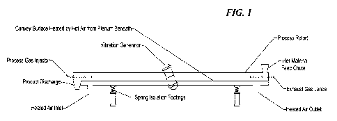
Figure 1. Schematic of VTA-CVI reactor comprising a heated air plenum.
Figure 2. Schematic of VTA-CVI reactor comprising a heated retort.
Figure 3. Schematic of VTA-CVI reactor comprising a heated retort and heated
outlet.
Figure 4. Capacity for half cells comprising SiC produced in the VTA-CVI
reactor.
Figure 5. Coulombic efficiency for half cells comprising SiC produced in the
VTA-CVI reactor.
DETAILED DESCRIPTION
In the following description, certain specific details are set forth in order
to
provide a thorough understanding of various embodiments. However, one skilled
in the
art will understand that the invention may be practiced without these details.
In other
instances, well-known structures have not been shown or described in detail to
avoid
5
CA 03191017 2023-02-07
WO 2022/035879 PCT/US2021/045417
unnecessarily obscuring descriptions of the embodiments. Unless the context
requires
otherwise, throughout the specification and claims which follow, the word
"comprise"
and variations thereof, such as, "comprises" and "comprising" are to be
construed in an
open, inclusive sense, that is, as "including, but not limited to." Further,
headings
provided herein are for convenience only and do not interpret the scope or
meaning of
the claimed invention.
Reference throughout this specification to "one embodiment" or "an
embodiment" means that a particular feature, structure or characteristic
described in
connection with the embodiment is included in at least one embodiment. Thus,
the
appearances of the phrases "in one embodiment" or "in an embodiment" in
various
places throughout this specification are not necessarily all referring to the
same
embodiment. Furthermore, the particular features, structures, or
characteristics may be
combined in any suitable manner in one or more embodiments. Also, as used in
this
specification and the appended claims, the singular forms "a," "an," and "the"
include
plural referents unless the content clearly dictates otherwise. It should also
be noted
that the term "or" is generally employed in its sense including "and/or"
unless the
content clearly dictates otherwise.
A. Porous Scaffold Materials
For the purposes of embodiments of the current invention, a porous scaffold
may be used, into which silicon is to be impregnated. In this context, the
porous
scaffold can comprise various materials. In some embodiments the porous
scaffold
material primarily comprises carbon, for example hard carbon. Other allotropes
of
carbon are also envisioned in other embodiments, for example, graphite,
amorphous
carbon, diamond, C60, carbon nanotubes (e.g., single and/or multi-walled),
graphene
and /or carbon fibers. The introduction of porosity into the carbon material
can be
achieved by a variety of means. For instance, the porosity in the carbon
material can be
achieved by modulation of polymer precursors, and/or processing conditions to
create
said porous carbon material, and described in detail in the subsequent
section.
6
CA 03191017 2023-02-07
WO 2022/035879 PCT/US2021/045417
In other embodiments, the porous scaffold comprises a polymer material. To
this end, a wide variety of polymers are envisioned in various embodiments to
have
utility, including, but not limited to, inorganic polymer, organic polymers,
and addition
polymers. Examples of inorganic polymers in this context includes, but are not
limited
to homochain polymers of silicon-silicon such as polysilanes, silicon carbide,
polygermanes, and polystannanes. Additional examples of inorganic polymers
includes, but are not limited to, heterochain polymers such as
polyborazylenes,
polysiloxanes like polydimethylsiloxane (PDMS), polymethylhydrosiloxane (PMHS)
and polydiphenylsiloxane, polysilazanes like perhydridopolysilazane (PHPS),
polyphosphazenes and poly(dichlorophosphazenes), polyphosphates, polythiazyls,
and
polysulfides. Examples of organic polymers includes, but are not limited to,
low
density polyethylene (LDPE), high density polyethylene (HDPE), polypropylene
(PP),
polyvinyl chloride (PVC), polystyrene (PS), nylon, nylon 6, nylon 6,6, teflon
(Polytetrafluoroethylene), thermoplastic polyurethanes (TPU), polyureas,
poly(lactide),
poly(glycolide) and combinations thereof, phenolic resins, polyamides,
polyaramids,
polyethylene terephthalate, polychloroprene, polyacrylonitrile, polyaniline,
polyimide,
poly(3,4-ethylenedioxythiophene) polystyrene sulfonate (PDOT:PSS), and others
known in the arts. The organic polymer can be synthetic or natural in origin.
In some
embodiments, the polymer is a polysaccharide, such as starch, cellulose,
cellobiose,
amylose, amylpectin, gum Arabic, lignin, and the like. In some embodiments,
the
polysaccharide is derived from the carmelization of mono- or oligomeric
sugars, such
as fructose, glucose, sucrose, maltose, raffinose, and the like.
In certain embodiments, the porous scaffold polymer material comprises a
coordination polymer. Coordination polymers in this context include, but are
not
limited to, metal organic frameworks (MOFs). Techniques for production of
MOFs, as
well as exemplary species of MOFs, are known and described in the art ("The
Chemistry and Applications of Metal-Organic Frameworks, Hiroyasu Furukawa et
al.
Science 341, (2013); DOT: 10.1126/science.1230444). Examples of MOFs in the
context include, but are not limited to, BasoliteTM materials and zeolitic
imidazolate
frameworks (ZIFs).
7
CA 03191017 2023-02-07
WO 2022/035879 PCT/US2021/045417
Concomitant with the myriad variety of polymers envisioned with the potential
to provide a porous substrate, various processing approaches are envisioned in
various
embodiments to achieve said porosity. In this context, general methods for
imparting
porosity into various materials are myriad, as known in the art, including,
but certainly
not limited to, methods involving emulsification, micelle creation,
gasification,
dissolution followed by solvent removal (for example, lyophilization), axial
compaction
and sintering, gravity sintering, powder rolling and sintering, isostatic
compaction and
sintering, metal spraying, metal coating and sintering, metal injection
molding and
sintering, and the like. Other approaches to create a porous polymeric
material,
including creation of a porous gel, such as a freeze dried gel, aerogel, and
the like are
also envisioned.
In certain embodiments, the porous scaffold material comprises a porous
ceramic material. In certain embodiments, the porous scaffold material
comprises a
porous ceramic foam. In this context, general methods for imparting porosity
into
ceramic materials are varied, as known in the art, including, but certainly
not limited to,
creation of porous In this context, general methods and materials suitable for
comprising the porous ceramic include, but are not limited to, porous aluminum
oxide,
porous zirconia toughened alumina, porous partially stabilized zirconia,
porous
alumina, porous sintered silicon carbide, sintered silicon nitride, porous
cordierite,
porous zirconium oxide, clay-bound silicon carbide, and the like.
In certain embodiments, the porous scaffold comprises porous silica or other
silicon material containing oxygen. The creation of silicon gels, including
sol gels, and
other porous silica materials is known in the art.
In certain embodiments, the porous material comprises a porous metal. Suitable
metals in this regard include, but are not limited to porous aluminum, porous
steel,
porous nickel, porous Inconcel, porous Hasteloy, porous titanium, porous
copper,
porous brass, porous gold, porous silver, porous germanium, and other metals
capable
of being formed into porous structures, as known in the art. In some
embodiments, the
porous scaffold material comprises a porous metal foam. The types of metals
and
methods to manufacture related to same are known in the art. Such methods
include,
8
CA 03191017 2023-02-07
WO 2022/035879 PCT/US2021/045417
but are not limited to, casting (including foaming, infiltration, and lost-
foam casting),
deposition (chemical and physical), gas-eutectic formation, and powder
metallurgy
techniques (such as powder sintering, compaction in the presence of a foaming
agent,
and fiber metallurgy techniques).
B. Porous Carbon Scaffold
Methods for preparing porous carbon materials from polymer precursors are
known in the art. For example, methods for preparation of carbon materials are
described in U.S. Patent Nos. 7,723,262, 8,293,818, 8,404,384, 8,654,507,
8,916,296,
9,269,502, 10,590,277, and U.S. patent application 16/745,197, the full
disclosures of
which are hereby incorporated by reference in their entireties for all
purposes.
Accordingly, in one embodiment the present disclosure provides a method for
preparing any of the carbon materials or polymer gels described above. The
carbon
materials may be synthesized through pyrolysis of either a single precursor,
for example
a saccharide material such as sucrose, fructose, glucose, dextrin,
maltodextrin, starch,
amylopectin, amlyose, lignin, gum Arabic, and other saccharides known in the
art, and
combinations thereof. Alternatively, the carbon materials may be synthesized
through
pyrolysis of a complex resin, for instance formed using a sol-gel method using
polymer
precursors such as phenol, resorcinol, bisphenol A, urea, melamine, and other
suitable
compounds known in the art, and combinations thereof, in a suitable solvent
such as
.. water, ethanol, methanol, and other solvents known in the art, and
combinations
thereof, with cross-linking agents such as formaldehyde,
hexamethylenetetramine,
furfural, and other cross-lining agents known in the art, and combinations
thereof. The
resin may be acid or basic, and may contain a catalyst. The catalyst may be
volatile or
non-volatile. The pyrolysis temperature and dwell time can vary as known in
the art.
In some embodiments, the methods comprise preparation of a polymer gel by a
sol gel process, condensation process or crosslinking process involving
monomer
precursor(s) and a crosslinking agent, two existing polymers and a
crosslinking agent or
a single polymer and a crosslinking agent, followed by pyrolysis of the
polymer gel.
9
CA 03191017 2023-02-07
WO 2022/035879
PCT/US2021/045417
The polymer gel may be dried (e.g., freeze dried) prior to pyrolysis; however
drying is
not necessarily required.
The target carbon properties can be derived from a variety of polymer
chemistries provided the polymerization reaction produces a resin/polymer with
the
necessary carbon backbone. Different polymer families include novolacs,
resoles,
acrylates, styrenics, ureathanes, rubbers (neoprenes, styrene-butadienes,
etc.), nylons,
etc. The preparation of any of these polymer resins can occur via a number of
different
processes including sol gel, emulsion/suspension, solid state, solution state,
melt state,
etc for either polymerization and crosslinking processes.
In some embodiments an electrochemical modifier is incorporated into the
material as polymer. For example, the organic or carbon containing polymer, RF
for
example, is copolymerized with the polymer, which contains the electrochemical
modifier. In one embodiment, the electrochemical modifier-containing polymer
contains silicon. In one embodiment the polymer is tetraethylorthosiliane
(TEOS). In
one embodiment, a TEOS solution is added to the RF solution prior to or during
polymerization. In another embodiment the polymer is a polysilane with organic
side
groups. In some cases these side groups are methyl groups, in other cases
these groups
are phenyl groups, in other cases the side chains include phenyl, pyrol,
acetate, vinyl,
siloxane fragments. In some cases the side chain includes a group 14 element
(silicon,
.. germanium, tin or lead). In other cases the side chain includes a group 13
element
(boron, aluminum, boron, gallium, indium). In other cases the side chain
includes a
group 15 element (nitrogen, phosphorous, arsenic). In other cases the side
chain
includes a group 16 element (oxygen, sulfur, selenium).
In another embodiment the electrochemical modifier comprises a silole. In
some cases it is a phenol-silole or a silafluorene. In other cases it is a
poly-silole or a
poly-silafluorene. In some cases the silicon is replaced with germanium
(germole or
germafluorene), tin (stannole or stannaflourene) nitrogen (carbazole) or
phosphorous
(phosphole, phosphafluorene). In all cases the heteroatom containing material
can be a
small molecule, an oligomer or a polymer. Phosphorous atoms may or may not be
also
bonded to oxygen.
CA 03191017 2023-02-07
WO 2022/035879 PCT/US2021/045417
In some embodiments the reactant comprises phosphorous. In certain other
embodiments, the phosphorus is in the form of phosphoric acid. In certain
other
embodiments, the phosphorus can be in the form of a salt, wherein the anion of
the salt
comprises one or more phosphate, phosphite, phosphide, hydrogen phosphate,
dihydrogen phosphate, hexafluorophosphate, hypophosphite, polyphosphate, or
pyrophosphate ions, or combinations thereof In certain other embodiments, the
phosphorus can be in the form of a salt, wherein the cation of the salt
comprises one or
more phosphonium ions. The non-phosphate containing anion or cation pair for
any of
the above embodiments can be chosen for those known and described in the art.
In the
context, exemplary cations to pair with phosphate-containing anions include,
but are not
limited to, ammonium, tetraethylammonium, and tetramethylammonium ions. In the
context, exemplary anions to pair with phosphate-containing cations include,
but are not
limited to, carbonate, dicarbonate, and acetate ions.
In some embodiments, the catalyst comprises a basic volatile catalyst. For
example, in one embodiment, the basic volatile catalyst comprises ammonium
carbonate, ammonium bicarbonate, ammonium acetate, ammonium hydroxide, or
combinations thereof In a further embodiment, the basic volatile catalyst is
ammonium
carbonate. In another further embodiment, the basic volatile catalyst is
ammonium
acetate.
In still other embodiments, the method comprises admixing an acid. In certain
embodiments, the acid is a solid at room temperature and pressure. In some
embodiments, the acid is a liquid at room temperature and pressure. In some
embodiments, the acid is a liquid at room temperature and pressure that does
not
provide dissolution of one or more of the other polymer precursors.
The acid may be selected from any number of acids suitable for the
polymerization process. For example, in some embodiments the acid is acetic
acid and
in other embodiments the acid is oxalic acid. In further embodiments, the acid
is mixed
with the first or second solvent in a ratio of acid to solvent of 99:1, 90:10,
75:25, 50:50,
25:75, 20:80, 10:90 or 1:90. In other embodiments, the acid is acetic acid and
the first
11
CA 03191017 2023-02-07
WO 2022/035879 PCT/US2021/045417
or second solvent is water. In other embodiments, acidity is provided by
adding a solid
acid.
The total content of acid in the mixture can be varied to alter the properties
of
the final product. In some embodiments, the acid is present from about 1% to
about
50% by weight of mixture. In other embodiments, the acid is present from about
5% to
about 25%. In other embodiments, the acid is present from about 10% to about
20%,
for example about 10%, about 15% or about 20%.
In certain embodiments, the polymer precursor components are blended together
and subsequently held for a time and at a temperature sufficient to achieve
polymerization. One or more of the polymer precursor components can have
particle
size less than about 20 mm in size, for example less than 10 mm, for example
less than
7 mm, for example, less than 5 mm, for example less than 2 mm, for example
less than
1 mm, for example less than 100 microns, for example less than 10 microns. In
some
embodiments, the particle size of one or more of the polymer precursor
components is
reduced during the blending process.
The blending of one or more polymer precursor components in the absence of
solvent can be accomplished by methods described in the art, for example ball
milling,
jet milling, Fritsch milling, planetary mixing, and other mixing methodologies
for
mixing or blending solid particles while controlling the process conditions
(e.g.,
temperature). The mixing or blending process can be accomplished before,
during,
and/or after (or combinations thereof) incubation at the reaction temperature.
Reaction parameters include aging the blended mixture at a temperature and for
a time sufficient for the one or more polymer precursors to react with each
other and
form a polymer. In this respect, suitable aging temperature ranges from about
room
temperature to temperatures at or near the melting point of one or more of the
polymer
precursors. In some embodiments, suitable aging temperature ranges from about
room
temperature to temperatures at or near the glass transition temperature of one
or more of
the polymer precursors. For example, in some embodiments the solvent free
mixture
is aged at temperatures from about 20 C to about 600 C, for example about 20
C to
about 500 C, for example about 20 C to about 400 C, for example about 20 C
to
12
CA 03191017 2023-02-07
WO 2022/035879 PCT/US2021/045417
about 300 C, for example about 20 C to about 200 C. In certain embodiments,
the
solvent free mixture is aged at temperatures from about 50 to about 250 C.
The reaction duration is generally sufficient to allow the polymer precursors
to
react and form a polymer, for example the mixture may be aged anywhere from 1
hour
to 48 hours, or more or less depending on the desired result. Typical
embodiments
include aging for a period of time ranging from about 2 hours to about 48
hours, for
example in some embodiments aging comprises about 12 hours and in other
embodiments aging comprises about 4-8 hours (e.g., about 6 hours).
In certain embodiments, an electrochemical modifier is incorporated during the
above described polymerization process. For example, in some embodiments, an
electrochemical modifier in the form of metal particles, metal paste, metal
salt, metal
oxide or molten metal can be dissolved or suspended into the mixture from
which the
gel resin is produced
Exemplary electrochemical modifiers for producing composite materials may
fall into one or more than one of the chemical classifications. In some
embodiments,
the electrochemical modifier is a lithium salt, for example, but not limited
to, lithium
fluoride, lithium chloride, lithium carbonate, lithium hydroxide, lithium
benzoate,
lithium bromide, lithium formate, lithium hexafluorophosphate, lithium iodate,
lithium
iodide, lithium perchlorate, lithium phosphate, lithium sulfate, lithium
tetraborate,
lithium tetrafluoroborate, and combinations thereof.
In certain embodiments, the electrochemical modifier comprises a metal, and
exemplary species includes, but are not limited to aluminum isoproproxide,
manganese
acetate, nickel acetate, iron acetate, tin chloride, silicon chloride, and
combinations
thereof. In certain embodiments, the electrochemical modifier is a phosphate
compound, including but not limited to phytic acid, phosphoric acid, ammonium
dihydrogenphosphate, and combinations thereof. In certain embodiments, the
electrochemical modifier comprises silicon, and exemplary species includes,
but are not
limited to silicon powders, silicon nanotubes, polycrystalline silicon,
nanocrystalline
silicon, amorpohous silicon, porous silicon, nano sized silicon, nano-featured
silicon,
13
CA 03191017 2023-02-07
WO 2022/035879 PCT/US2021/045417
nano-sized and nano-featured silicon, silicyne, and black silicon, and
combinations
thereof.
Electrochemical modifiers can be combined with a variety of polymer systems
through either physical mixing or chemical reactions with latent (or
secondary) polymer
functionality. Examples of latent polymer functionality include, but are not
limited to,
epoxide groups, unsaturation (double and triple bonds), acid groups, alcohol
groups,
amine groups, basic groups. Crosslinking with latent functionality can occur
via
heteroatoms (e.g. vulcanization with sulfur, acid/base/ring opening reactions
with
phosphoric acid), reactions with organic acids or bases (described above),
coordination
to transition metals (including but not limited to Ti, Cr, Mn, Fe, Co, Ni, Cu,
Zn, Zr, Nb,
Mo, Ag, Au), ring opening or ring closing reactions (rotaxanes, spiro
compounds, etc).
Electrochemical modifiers can also be added to the polymer system through
physical blending. Physical blending can include but is not limited to melt
blending of
polymers and/or co-polymers, the inclusion of discrete particles, chemical
vapor
deposition of the electrochemical modifier and coprecipitation of the
electrochemical
modifier and the main polymer material.
In some instances the electrochemical modifier can be added via a metal salt
solid, solution, or suspension. The metal salt solid, solution or suspension
may comprise
acids and/or alcohols to improve solubility of the metal salt. In yet another
variation,
the polymer gel (either before or after an optional drying step) is contacted
with a paste
comprising the electrochemical modifier. In yet another variation, the polymer
gel
(either before or after an optional drying step) is contacted with a metal or
metal oxide
sol comprising the desired electrochemical modifier.
In addition to the above exemplified electrochemical modifiers, the composite
materials may comprise one or more additional forms (i.e., allotropes) of
carbon. In
this regard, it has been found that inclusion of different allotropes of
carbon such as
graphite, amorphous carbon, conductive carbon, carbon black, diamond, C60,
carbon
nanotubes (e.g., single and/or multi-walled), graphene and /or carbon fibers
into the
composite materials is effective to optimize the electrochemical properties of
the
composite materials. The various allotropes of carbon can be incorporated into
the
14
CA 03191017 2023-02-07
WO 2022/035879 PCT/US2021/045417
carbon materials during any stage of the preparation process described herein.
For
example, during the solution phase, during the gelation phase, during the
curing phase,
during the pyrolysis phase, during the milling phase, or after milling. In
some
embodiments, the second carbon form is incorporated into the composite
material by
adding the second carbon form before or during polymerization of the polymer
gel as
described in more detail herein. The polymerized polymer gel containing the
second
carbon form is then processed according to the general techniques described
herein to
obtain a carbon material containing a second allotrope of carbon.
In a preferred embodiment, the carbon is produced from precursors with little
or
no solvent required for processing (solvent free). The structure of the
polymer
precursors suitable for use in a low solvent or essentially solvent free
reaction mixture
is not particularly limited, provided that the polymer precursor is capable of
reacting
with another polymer precursor or with a second polymer precursor to form a
polymer.
Polymer precursors include amine-containing compounds, alcohol-containing
compounds and carbonyl-containing compounds, for example in some embodiments
the
polymer precursors are selected from an alcohol, a phenol, a polyalcohol, a
sugar, an
alkyl amine, an aromatic amine, an aldehyde, a ketone, a carboxylic acid, an
ester, a
urea, an acid halide and an isocyanate.
In one embodiment employing a low or essentially solvent free reaction
mixture,
the method comprises use of a first and second polymer precursor, and in some
embodiments the first or second polymer precursor is a carbonyl containing
compound
and the other of the first or second polymer precursor is an alcohol
containing
compound. In some embodiments, a first polymer precursor is a phenolic
compound
and a second polymer precursor is an aldehyde compound (e.g., formaldehyde).
In one
embodiment, of the method the phenolic compound is phenol, resorcinol,
catechol,
hydroquinone, phloroglucinol, or a combination thereof; and the aldehyde
compound is
formaldehyde, acetaldehyde, propionaldehyde, butyraldehyde, benzaldehyde,
cinnamaldehyde, or a combination thereof. In a further embodiment, the
phenolic
compound is resorcinol, phenol or a combination thereof, and the aldehyde
compound
is formaldehyde. In yet further embodiments, the phenolic compound is
resorcinol and
CA 03191017 2023-02-07
WO 2022/035879 PCT/US2021/045417
the aldehyde compound is formaldehyde. In some embodiments, the polymer
precursors are alcohols and carbonyl compounds (e.g., resorcinol and aldehyde)
and
they are present in a ratio of about 0.5:1.0, respectively.
The polymer precursor materials suitable for low or essentially solvent free
reaction mixture as disclosed herein include (a) alcohols, phenolic compounds,
and
other mono- or polyhydroxy compounds and (b) aldehydes, ketones, and
combinations
thereof. Representative alcohols in this context include straight chain and
branched,
saturated and unsaturated alcohols. Suitable phenolic compounds include
polyhydroxy
benzene, such as a dihydroxy or trihydroxy benzene. Representative polyhydroxy
benzenes include resorcinol (i.e., 1,3-dihydroxy benzene), catechol,
hydroquinone, and
phloroglucinol. Other suitable compounds in this regard are bisphenols, for
instance,
bisphenol A. Mixtures of two or more polyhydroxy benzenes can also be used.
Phenol
(monohydroxy benzene) can also be used. Representative polyhydroxy compounds
include sugars, such as glucose, sucrose, fructose, chitin and other polyols,
such as
mannitol. Aldehydes in this context include: straight chain saturated aldeydes
such as
methanal (formaldehyde), ethanal (acetaldehyde), propanal (propionaldehyde),
butanal
(butyraldehyde), and the like; straight chain unsaturated aldehydes such as
ethenone and
other ketenes, 2-propenal (acrylaldehyde), 2-butenal (crotonaldehyde), 3
butenal, and
the like; branched saturated and unsaturated aldehydes; and aromatic-type
aldehydes
such as benzaldehyde, salicylaldehyde, hydrocinnamaldehyde, and the like.
Suitable
ketones include: straight chain saturated ketones such as propanone and 2
butanone, and
the like; straight chain unsaturated ketones such as propenone, 2 butenone,
and 3
butenone (methyl vinyl ketone) and the like; branched saturated and
unsaturated
ketones; and aromatic-type ketones such as methyl benzyl ketone
(phenylacetone),
ethyl benzyl ketone, and the like. The polymer precursor materials can also be
combinations of the precursors described above.
In some embodiments, one polymer precursor in the low or essentially solvent
free reaction mixture is an alcohol-containing species and another polymer
precursor is
a carbonyl-containing species. The relative amounts of alcohol-containing
species (e.g.,
alcohols, phenolic compounds and mono- or poly- hydroxy compounds or
combinations
16
CA 03191017 2023-02-07
WO 2022/035879 PCT/US2021/045417
thereof) reacted with the carbonyl containing species (e.g. aldehydes, ketones
or
combinations thereof) can vary substantially. In some embodiments, the ratio
of
alcohol-containing species to aldehyde species is selected so that the total
moles of
reactive alcohol groups in the alcohol-containing species is approximately the
same as
the total moles of reactive carbonyl groups in the aldehyde species.
Similarly, the ratio
of alcohol-containing species to ketone species may be selected so that the
total moles
of reactive alcohol groups in the alcohol containing species is approximately
the same
as the total moles of reactive carbonyl groups in the ketone species. The same
general
1:1 molar ratio holds true when the carbonyl-containing species comprises a
combination of an aldehyde species and a ketone species.
In other embodiments, the polymer precursor in the low or essentially solvent
free reaction mixture is a urea or an amine containing compound. For example,
in some
embodiments the polymer precursor is urea, melamine, hexamethylenetetramine
(HMT)
or combination thereof. Other embodiments include polymer precursors selected
from
isocyanates or other activated carbonyl compounds such as acid halides and the
like.
Some embodiments of the disclosed methods include preparation of low or
solvent-free polymer gels (and carbon materials) comprising electrochemical
modifiers.
Such electrochemical modifiers include, but are not limited to nitrogen,
silicon, and
sulfur. In other embodiments, the electrochemical modifier comprises fluorine,
iron,
tin, silicon, nickel, aluminum, zinc, or manganese. The electrochemical
modifier can be
included in the preparation procedure at any step. For example, in some the
electrochemical modifier is admixed with the mixture, the polymer phase or the
continuous phase.
The blending of one or more polymer precursor components in the absence of
solvent can be accomplished by methods described in the art, for example ball
milling,
jet milling, Fritsch milling, planetary mixing, and other mixing methodologies
for
mixing or blending solid particles while controlling the process conditions
(e.g.,
temperature). The mixing or blending process can be accomplished before,
during,
and/or after (or combinations thereof) incubation at the reaction temperature.
17
CA 03191017 2023-02-07
WO 2022/035879 PCT/US2021/045417
Reaction parameters include aging the blended mixture at a temperature and for
a time sufficient for the one or more polymer precursors to react with each
other and
form a polymer. In this respect, suitable aging temperature ranges from about
room
temperature to temperatures at or near the melting point of one or more of the
polymer
precursors. In some embodiments, suitable aging temperature ranges from about
room
temperature to temperatures at or near the glass transition temperature of one
or more of
the polymer precursors. For example, in some embodiments the solvent free
mixture
is aged at temperatures from about 20 C to about 600 C, for example about 20
C to
about 500 C, for example about 20 C to about 400 C, for example about 20 C
to
about 300 C, for example about 20 C to about 200 C. In certain embodiments,
the
solvent free mixture is aged at temperatures from about 50 to about 250 C.
The porous carbon material can be achieved via pyrolysis of a polymer
produced from precursors materials as described above. In some embodiments,
the
porous carbon material comprises an amorphous activated carbon that is
produced by
pyrolysis, physical or chemical activation, or combination thereof in either a
single
process step or sequential process steps.
The temperature and dwell time of pyrolysis can be varied, for example the
dwell time van vary from 1 min to 10 min, from 10 min to 30 min, from 30 min
to 1
hour, for 1 hour to 2 hours, from 2 hours to 4 hours, from 4 hours to 24 h.
The
temperature can be varied, for example, the pyrolysis temperature can vary
from 200 to
300 C, from 250 to 350 C, from 350 C to 450 C, from 450 C to 550 C, from 540 C
to
650 C, from 650 C to 750 C, from 750 C to 850 C, from 850 C to 950 C, from 950
C to
1050 C, from 1050 C to 1150 C, from 1150 C to 1250 C. The pyrolysis can be
accomplished in an inert gas, for example nitrogen, or argon.
In some embodiments, an alternate gas is used to further accomplish carbon
activation. In certain embodiments, pyrolysis and activation are combined.
Suitable
gases for accomplishing carbon activation include, but are not limited to,
carbon
dioxide, carbon monoxide, water (steam), air, oxygen, and further combinations
thereof
The temperature and dwell time of activation can be varied, for example the
dwell time
van vary from 1 min to 10 min, from 10 min to 30 min, from 30 min to 1 hour,
for 1
18
CA 03191017 2023-02-07
WO 2022/035879 PCT/US2021/045417
hour to 2 hours, from 2 hours to 4 hours, from 4 hours to 24 h. The
temperature can be
varied, for example, the pyrolysis temperature can vary from 200 to 300 C,
from 250 to
350 C, from 350 C to 450 C, from 450 C to 550 C, from 540 C to 650 C, from 650
C to
750 C, from 750 C to 850 C, from 850 C to 950 C, from 950 C to 1050 C, from
1050 C
to 1150 C, from 1150 C to 1250 C.
Either prior to the pyrolysis, and/or after pyrolysis, and/or after
activation, the
carbon may be subjected to a particle size reduction. The particle size
reduction can be
accomplished by a variety of techniques known in the art, for example by jet
milling in
the presence of various gases including air, nitrogen, argon, helium,
supercritical steam,
and other gases known in the art. Other particle size reduction methods, such
as
grinding, ball milling, jet milling, water jet milling, and other approaches
known in the
art are also envisioned.
The porous carbon scaffold may be in the form of particles. The particle size
and particle size distribution can be measured by a variety of techniques
known in the
art, and can be described based on fractional volume. In this regard, the
Dv,50 of the
carbon scaffold may be between 10 nm and 10 mm, for example between 100 nm and
1
mm, for example between 1 um and 100 um, for example between 2 um and 50 um,
example between 3 um and 30 um, example between 4 um and 20 um, example
between 5 um and 10 um. In certain embodiments, the Dv,50 is less than 1 mm,
for
example less than 100 um, for example less than 50 um, for example less than
30 um,
for example less than 20 um, for example less than 10 um, for example less
than 8 um,
for example less than 5 um, for example less than 3 um, for example less than
1 um. In
certain embodiments, the Dv,100 is less than 1 mm, for example less than 100
um, for
example less than 50 um, for example less than 30 um, for example less than 20
um, for
example less than 10 um, for example less than 8 um, for example less than 5
um, for
example less than 3 um, for example less than 1 um. In certain embodiments,
the Dv,99
is less than 1 mm, for example less than 100 um, for example less than 50 um,
for
example less than 30 um, for example less than 20 um, for example less than 10
um, for
example less than 8 um, for example less than 5 um, for example less than 3
um, for
example less than 1 um. In certain embodiments, the Dv,90 is less than 1 mm,
for
19
CA 03191017 2023-02-07
WO 2022/035879 PCT/US2021/045417
example less than 100 um, for example less than 50 um, for example less than
30 um,
for example less than 20 um, for example less than 10 um, for example less
than 8 um,
for example less than 5 um, for example less than 3 um, for example less than
1 um. In
certain embodiments, the Dv,0 is greater than 10 nm, for example greater than
100 nm,
for example greater than 500 nm, for example greater than 1 um, for example
greater
than 2 um, for example greater than 5 um, for example greater than 10 um. In
certain
embodiments, the Dv,1 is greater than 10 nm, for example greater than 100 nm,
for
example greater than 500 nm, for example greater than 1 um, for example
greater than 2
um, for example greater than 5 um, for example greater than 10 um. In certain
embodiments, the Dv,10 is greater than 10 nm, for example greater than 100 nm,
for
example greater than 500 nm, for example greater than 1 um, for example
greater than 2
um, for example greater than 5 um, for example greater than 10 um.
In some embodiments, the surface area of the porous carbon scaffold can
comprise a surface area greater than 400 m2/g, for example greater than 500
m2/g, for
example greater than 750 m2/g, for example greater than 1000 m2/g, for example
greater than 1250 m2/g, for example greater than 1500 m2/g, for example
greater than
1750 m2/g, for example greater than 2000 m2/g, for example greater than 2500
m2/g,
for example greater than 3000 m2/g. In other embodiments, the surface area of
the
porous carbon scaffold can be less than 500 m2/g. In some embodiments, the
surface
area of the porous carbon scaffold is between 200 and 500 m2/g. In some
embodiments, the surface area of the porous carbon scaffold is between 100 and
200
m2/g. In some embodiments, the surface area of the porous carbon scaffold is
between
50 and 100 m2/g. In some embodiments, the surface area of the porous carbon
scaffold
is between 10 and 50 m2/g. In some embodiments, the surface area of the porous
carbon scaffold can be less than 10 m2/g.
In some embodiments, the pore volume of the porous carbon scaffold is greater
than 0.4 cm3/g, for example greater than 0.5 cm3/g, for example greater than
0.6 cm3/g,
for example greater than 0.7 cm3/g, for example greater than 0.8 cm3/g, for
example
greater than 0.9 cm3/g, for example greater than 1.0 cm3/g, for example
greater than
1.1 cm3/g, for example greater than 1.2 cm3/g, for example greater than 1.4
cm3/g, for
CA 03191017 2023-02-07
WO 2022/035879 PCT/US2021/045417
example greater than 1.6 cm3/g, for example greater than 1.8 cm3/g, for
example
greater than 2.0 cm3/g. In other embodiments, the pore volume of the porous
silicon
scaffold is less than 0.5 cm3, for example between 0.1 cm3/g and 0.5 cm3/g. In
certain
other embodiments, the pore volume of the porous silicon scaffold is between
0.01
cm3/g and 0.1 cm3/g.
In some other embodiments, the porous carbon scaffold is an amorphous
activated carbon with a pore volume between 0.2 and 2.0 cm3/g. In certain
embodiments, the carbon is an amorphous activated carbon with a pore volume
between
0.4 and 1.5 cm3/g. In certain embodiments, the carbon is an amorphous
activated
carbon with a pore volume between 0.5 and 1.2 cm3/g. In certain embodiments,
the
carbon is an amorphous activated carbon with a pore volume between 0.6 and 1.0
cm3/g.
In some other embodiments, the porous carbon scaffold comprises a tap density
of less than 1.0 g/cm3, for example less than 0.8 g/cm3, for example less than
0.6
g/cm3, for example less than 0.5 g/cm3, for example less than 0.4 g/cm3, for
example
less than 0.3 g/cm3, for example less than 0.2 g/cm3, for example less than
0.1 g/cm3.
The surface functionality of the porous carbon scaffold can vary. One property
which can be predictive of surface functionality is the pH of the porous
carbon scaffold.
The presently disclosed porous carbon scaffolds comprise pH values ranging
from less
than 1 to about 14, for example less than 5, from 5 to 8 or greater than 8. In
some
embodiments, the pH of the porous carbon is less than 4, less than 3, less
than 2 or even
less than 1. In other embodiments, the pH of the porous carbon is between
about 5 and
6, between about 6 and 7, between about 7 and 8 or between 8 and 9 or between
9 and
10. In still other embodiments, the pH is high and the pH of the porous carbon
ranges is
greater than 8, greater than 9, greater than 10, greater than 11, greater than
12, or even
greater than 13.
The pore volume distribution of the porous carbon scaffold can vary. For
example, the % micropores can comprise less than 30%, for example less than
20%, for
example less than 10%, for example less than 5%, for example less than 4%, for
example less than 3%, for example less than 2%, for example less than 1%, for
example
21
CA 03191017 2023-02-07
WO 2022/035879 PCT/US2021/045417
less than 0.5%, for example less than 0.2%, for example, less than 0.1%. In
certain
embodiments, there is no detectable micropore volume in the porous carbon
scaffold.
The mesopores comprising the porous carbon scaffold can vary. For example,
the % mesopores can comprise less than 30%, for example less than 20%, for
example
less than 10%, for example less than 5%, for example less than 4%, for example
less
than 3%, for example less than 2%, for example less than 1%, for example less
than
0.5%, for example less than 0.2%, for example, less than 0.1%. In certain
embodiments,
there is no detectable mesopore volume in the porous carbon scaffold.
In some embodiments, the pore volume distribution of the porous carbon
scaffold comprises more than 50% macropores, for example more than 60%
macropores, for example more than 70% macropores, for example more than 80%
macropores, for example more than 90% macropores, for example more than 95%
macropores, for example more than 98% macropores, for example more than 99%
macropores, for example more than 99.5% macropores, for example more than
99.9%
macropores.
In certain preferred embodiments, the pore volume of the porous carbon
scaffold
comprises a blend of micropores, mesopores, and macropores. Accordingly, in
certain
embodiments, the porous carbon scaffold comprises 0-20% micropores, 30-70%
mesopores, and less than 10% macropores. In certain other embodiments, the
porous
carbon scaffold comprises 0-20% micropores, 0-20% mesopores, and 70-95%
macropores. In certain other embodiments, the porous carbon scaffold comprises
20-
50% micropores, 50-80% mesopores, and 0-10% macropores. In certain other
embodiments, the porous carbon scaffold comprises 40-60% micropores, 40-60%
mesopores, and 0-10% macropores. In certain other embodiments, the porous
carbon
scaffold comprises 80-95% micropores, 0-10% mesopores, and 0-10% macropores.
In
certain other embodiments, the porous carbon scaffold comprises 0-10%
micropores,
30-50% mesopores, and 50-70% macropores. In certain other embodiments, the
porous
carbon scaffold comprises 0-10% micropores, 70-80% mesopores, and 0-20%
macropores. In certain other embodiments, the porous carbon scaffold comprises
0-
20% micropores, 70-95% mesopores, and 0-10% macropores. In certain other
22
CA 03191017 2023-02-07
WO 2022/035879 PCT/US2021/045417
embodiments, the porous carbon scaffold comprises 0-10% micropores, 70-95%
mesopores, and 0-20% macropores.
In certain embodiments, the % of pore volume in the porous carbon scaffold
representing pores between 100 and 1000 A (10 and 100 nm) comprises greater
than
30% of the total pore volume, for example greater than 40% of the total pore
volume,
for example greater than 50% of the total pore volume, for example greater
than 60% of
the total pore volume, for example greater than 70% of the total pore volume,
for
example greater than 80% of the total pore volume, for example greater than
90% of the
total pore volume, for example greater than 95% of the total pore volume, for
example
greater than 98% of the total pore volume, for example greater than 99% of the
total
pore volume, for example greater than 99.5% of the total pore volume, for
example
greater than 99.9% of the total pore volume.
In certain embodiments, the skeletal density of the porous carbon scaffold
ranges from about 1 g/cc to about 3 g/cc, for example from about 1.5 g/cc to
about 2.3
g/cc. In other embodiments, the skeletal density ranges from about 1.5 cc/g to
about 1.6
cc/g, from about 1.6 cc/g to about 1.7 cc/g, from about 1.7 cc/g to about 1.8
cc/g, from
about 1.8 cc/g to about 1.9 cc/g, from about 1.9 cc/g to about 2.0 cc/g, from
about 2.0
cc/g to about 2.1 cc/g, from about 2.1 cc/g to about 2.2 cc/g or from about
2.2 cc/g to
about 2.3 cc/g, from about 2.3 cc to about 2.4 cc/g, for example from about
2.4 cc/g to
about 2.5 cc/g.
C. Vibro-Thermally Assisted Chemical Vapor Infiltration (VTA-CVI)
One traditional approach to creating a composite material is to subject a
substrate material to elevated temperature in the presence of a thermally
decomposing
gas. For example, a related process known in the art is chemical vapor
deposition
(CVD), wherein a substrate provides a solid surface comprising the first
component of
the composite, and the gas thermally decomposes on this solid surface to
provide the
second component of composite. Such a CVD approach can be employed, for
instance,
to create Si-C composite materials wherein the silicon is coating on the
outside surface
of silicon particles. Alternatively, chemical vapor infiltration (CVI) is a
process wherein
23
CA 03191017 2023-02-07
WO 2022/035879
PCT/US2021/045417
a substrate provides a porous scaffold comprising the first component of the
composite,
and the gas thermally decomposes on into the porosity (into the pores) of the
porous
scaffold material to provide the second component of composite.
In an embodiment, silicon is created within the pores of the porous carbon
.. scaffold by subjecting the porous carbon particles to a silicon containing
precursor gas
at elevated temperature and the presence of a silicon-containing gas,
preferably silane,
in order to decompose said gas into silicon. The silicon containing precursor
gas can be
mixed with other inert gases, for example, nitrogen gas. The temperature and
time of
processing can be varied, for example the temperature can be between 200 and
900 C,
.. for example between 200 and 250 C, for example between 250 and 300 C, for
example
between 300 and 350 C, for example between 300 and 400 C, for example between
350
and 450 C, for example between 350 and 400 C, for example between 400 and 500
C,
for example between 500 and 600 C, for example between 600 and 700 C, for
example
between 700 and 800 C, for example between 800 and 900 C, for example between
600
.. and 1100 C.
In certain embodiment, the porosity of the particulate carbon particles can be
increased by activation within the VTA¨CVI reactor by introducing an
activation gas,
comprising, but not limited to, CO2, steam, and combinations thereof. The
activation
temperature can be varied, for example, between 600 and 1200 C, for example
between
.. 600 and 800 C, for example between 700 and 900 C, for example between 800
and
1000 C, for example between 800 and 1100 C. In certain embodiments, the
resulting
particulate porous carbon particles can further traverse into the subsequent
zone in the
VTA¨CVI reactor to accomplish CVI under the process conditions as described
elsewhere in this disclosure.
In certain embodiments, the flow of the silicon containing precursor gas is co-
current, i.e., flows in the same direction as the porous carbon particles
traverse the
heated zone. In certain preferred embodiments, the flow of the silicon
containing
precursor gas is counter-current, i.e., flows in the opposite direction as the
porous
carbon particles traverse the heated zone.
24
CA 03191017 2023-02-07
WO 2022/035879 PCT/US2021/045417
The mixture of gas can comprise between 0.1 and 1 % silane and remainder
inert gas. Alternatively, the mixture of gas can comprise between 1% and 10%
silane
and remainder inert gas. Alternatively, the mixture of gas can comprise
between 10%
and 20% silane and remainder inert gas. Alternatively, the mixture of gas can
comprise
between 20% and 50% silane and remainder inert gas. Alternatively, the mixture
of gas
can comprise above 50% silane and remainder inert gas. Alternatively, the gas
can
essentially be 100% silane gas. Suitable inert gases include, but are not
limited to,
hydrogen, nitrogen, argon, and combinations thereof
There are several critical challenges to scalable and cost-effective CVI
processing. These key challenges include overcoming the gas-solid diffusional
barrier,
i.e., barrier for the reactant gas to enter into the pores of the scaffold
material and for
by-product gas to exit the pores of the scaffold material, achieving
sufficient heat
transfer to accomplish the decomposition reaction, achieving temperature
uniformity of
the reacting material, and achieving porous scaffold material flowability.
These
challenges can be overcome, and other benefits obtained as well, by the
current VTA-
CVI invention described herein.
VTA-CVI is a process wherein a particulate scaffold material is conveyed by
vibration through the heated region of a reactor in the presence of a
thermally
decomposing gas. While not being bound by theory or application, in a
preferred
embodiment the VTA-CVI process can be employed to produce a silicon-carbon
composite material.
D. VTA-CVI to Produce Silicon-Carbon Composite Materials
The VTA-CVI process can be carried out as follows. The particulate porous
carbon scaffold is introduced within a retort, wherein said retort is vibrated
such that the
particulate porous carbon is conveyed through the retort, and said retort
comprises a
heated zone. For the purpose of this disclosure, the term "retort" refers to a
vessel
comprising a zone in which the porous scaffold is heated, and whose geometry
can be
varied, and is contained within the heated zone of the reactor. In certain
preferred
embodiments, the carbon scaffold particles are conveyed across a rectangular
surface.
CA 03191017 2023-02-07
WO 2022/035879 PCT/US2021/045417
The VTA-CVI process can be run is various modes, for example, as batch, semi-
batch,
or continuous process.
The conveyance rate of the material within the retort of the VTA-CVI reactor
can be varied, for example by varying the amplitude and frequency of the
vibration, as
well as the location(s) at which vibration is applied to the retort. In
certain
embodiments, the amplitude is between 0.1 mm to 1 m, for example 1 mm to 100
cm,
for example 1 cm to 10 cm. In preferred embodiments, the amplitude of the
vibrating
retort varies between 0.01 mm and 10 cm.
The frequency of the vibration can be varied, for example between 0.01 to 100
Hz, for example between 0.1 Hz to 10 Hz. In preferred embodiments, the
frequency of
the vibration is between 1 Hz to 100 Hz.
In certain embodiments, the vibration is applied to the retort at the entrance
of
the reactor, that is, the position at which the feed carbon scaffold material
is introduced
into the retort. In certain embodiments, the position at which the feed porous
carbon
scaffold material is introduced into the retort coincides with the beginning
of the heated
zone. In certain embodiments, the vibration is applied to the retort at the
exit of the
heated zone. In certain embodiments, vibration is applied at a location
between the
points where the porous scaffold material enters and exits the retort, and/or
between the
beginning and end of the heated zone. In certain embodiments, vibration is
applied to
the retort at more than one position within the heated zone, such as entry,
exit, and/or
one or more locations in between, that is, one or more positions within the
heated zone.
In certain embodiments, the porous carbon material is introduced to the VTA-
CVI retort upstream of the heated zone. In certain embodiments, the porous
carbon
material is introduced to the VTA-CVI retort upstream of the heated zone and
upstream
of any position or positions where vibration is applied.
In one embodiment, vibration is applied in one position, and that position is
not
within the heated zone. In one embodiment, vibration is applied in one
position, and
said position is not within the heated zone, and said position is upstream of
the heated
zone relative to the movement of porous carbon scaffold material through the
hot zone.
In one embodiment, vibration is applied in one position, and said position is
not within
26
CA 03191017 2023-02-07
WO 2022/035879 PCT/US2021/045417
the heated zone, and said position is downstream of the heated zone relative
to the
movement of porous carbon scaffold material through the hot zone.
In one embodiment, vibration is applied in more than one position, and one or
more of said positions are not within the heated zone. In one embodiment,
vibration is
applied in more than one position, and one or more of said positions are not
within the
heated zone, and one or more of said positions are upstream of the heated zone
relative
to the movement of porous carbon scaffold material through the hot zone. In
one
embodiment, vibration is applied in more than one position, and one or more of
said
positions are not within the heated zone, and one or more of said positions
are
downstream of the heated zone relative to the movement of porous carbon
scaffold
material through the hot zone.
In certain embodiments where vibration is applied at a single position, the
frequency and/or amplitude is held constant. In certain embodiments where
vibration is
applied at a more than one position, the frequency and/or amplitude is held
constant at
each position, and is the same for all positions where vibration is applied.
In certain embodiments where vibration is applied at a more than one position,
the frequency and/or amplitude is held constant at each position where
vibration is
applied, and is not the same for all positions where vibration is applied.
In certain embodiments where vibration is applied at more than one position,
the
frequency and amplitude are held constant at each position where vibration is
applied,
and the frequency is sequentially increased at each position where vibration
is applied
in the direction of sample progresses through the heated zone. In certain
embodiments
where vibration is applied at more than one position, the frequency and
amplitude are
held constant at each position where vibration is applied, and the frequency
is
sequentially decreased at each position where vibration is applied in the
direction of
sample progresses through the heated zone.
In certain embodiments where vibration is applied at more than one position,
the
frequency and amplitude are held constant at each position where vibration is
applied,
and the amplitude is sequentially increased at each position where vibration
is applied
in the direction of sample progresses through the heated zone. In certain
embodiments
27
CA 03191017 2023-02-07
WO 2022/035879 PCT/US2021/045417
where vibration is applied at more than one position, the frequency and
amplitude are
held constant at each position where vibration is applied, and the amplitude
is
sequentially decreased at each position where vibration is applied in the
direction of
sample progresses through the heated zone.
In certain embodiments where vibration is applied at more than one position,
the
frequency and amplitude are held constant at each position where vibration is
applied,
and the amplitude and frequency are sequentially increased at each position
where
vibration is applied in the direction of sample progresses through the heated
zone. In
certain embodiments where vibration is applied at more than one position, the
frequency and amplitude are held constant at each position where vibration is
applied,
and the amplitude and frequency are sequentially decreased at each position
where
vibration is applied in the direction of sample progresses through the heated
zone.
In certain embodiments where vibration is applied at more than one position,
the
frequency and amplitude are held constant at each position where vibration is
applied,
and the amplitude is sequentially increased and frequency is sequentially
decreased at
each position where vibration is applied in the direction of sample progresses
through
the heated zone. In certain embodiments where vibration is applied at more
than one
position, the frequency and amplitude are held constant at each position where
vibration
is applied, and the amplitude is sequentially decreased and frequency is
sequentially
.. increased at each position where vibration is applied in the direction of
sample
progresses through the heated zone.
In certain embodiments where vibration is applied at a single position, the
frequency and/or amplitude is varied over time. In certain embodiments where
vibration is applied at more than one positon single position, the frequency
and/or
amplitude is varied over time at one or more of the positions where vibrtions
are
applied.
In certain embodiments where vibration is applied at more than one positon
single position, the frequency and/or amplitude is varied over time at one or
more of the
positions where vibrations are applied with the result of maintaining porous
carbon
28
CA 03191017 2023-02-07
WO 2022/035879 PCT/US2021/045417
scaffold material within the heated zone. In this latter embodiment, the
process can be
a batch or semi-batch process.
In certain embodiments, the VTA-CVI process can be combined with other
process or processes. For example, pyrolyzed porous carbon particles can
traverse
through the reactor in two zones, wherein the pyrolyzed carbon particles
traverse
though a first zone, and this first zone is an activation zone, wherein
vibration is applied
at one position or more than one position within the first heated zone, and
subsequently
the resulting activated porous carbon particles traverse through the second
zone,
wherein vibration is applied at one position or more than one position within
the second
heated zone, and this second zone is the VTA-CVI zone.
In certain embodiments, a particle size reduction is accomplished to the
porous
carbon material before the VTA-CVI process. In certain embodiments, a particle
size
reduction is accomplished to the porous carbon material after the VTA-CVI
process. In
certain embodiments, a particle size reduction is accomplished to the porous
carbon
material before and after the VTA-CVI process. In certain embodiments, a
particle size
reduction is accomplished to the pyrolyzed carbon material before the VTA-CVI
process. In certain embodiments, a particle size reduction is accomplished to
the
pyrolzyed carbon material after the VTA-CVI process. In certain embodiments, a
particle size reduction is accomplished to the pyrolzyed carbon material
before and after
the VTA-CVI process.
In certain embodiments, vibration is applied at one position, or more than one
position, and the porous carbon material traverses through the heated zone at
a constant
rate, i.e., same rate at each position within the heated zone. In certain
other
embodiments, vibration is more than one position, and the porous carbon
material
traverses through the heated zone at a non-constant rate. A preferred mode for
this
latter embodiment is the case where the porous carbon accelerates as the
material
progresses thought the heated zone. Without being bound by theory, this latter
mode
results in more precise control over the porous carbon material accurately
achieving the
final desired level of silicon loading.
29
CA 03191017 2023-02-07
WO 2022/035879 PCT/US2021/045417
The areal loading of the porous carbon material for vary, for example from
0.01
to 1000 g/cm2, for example from 0.1 to 100 g/cm2, for example from 0.1 to 50
g/cm2,
for example from 0.1 to 40 g/cm2, for example from 0.1 to 20 g/cm2, for
example from
0.1 to 10 g/cm2, for example from 0.1 to 5 g/cm2, for example from 0.1 to 2
g/cm2, for
example from 0.1 to 1 g/cm2. In certain embodiments, the area loading of the
porous
carbon material varies as the material traverses through the heated zone. In
certain
embodiments, the area loading of the porous carbon material decreases as the
material
traverses through the heated zone. In certain embodiments, the area loading of
the
porous carbon material increases as the material traverses through the heated
zone. In
certain embodiments, the area loading of the porous carbon material increases
and the
silicon content of the porous carbon particles increases as the material
traverses through
the heated zone.
The conveyance rate of porous carbon scaffold material can be varied. For
example, the conveyance rate can be described as a linear velocity, and can
vary from
0.01 to 1000 m/h, for example from 0.1 to 100 m/g, for example from 0.1 to 10
m/g, for
example from 0.1 to 5 m/g, for example from 0.1 to 2 m/g, for example from 0.1
to 1
m/g,
The certain embodiments, vibration is applied continuously. In other
embodiments, vibration is applied non-continuously, i.e., as pulses separated
by period
where no vibration is applied. According to these embodiments, the duration of
pulses
can be varied, for example from 1 sec to 10 h, for example from 1 sec to 1 h,
for
example from 1 sec to 30 min, for example from 10 sec to 10 min. In a similar
fashion,
the duration of pulses can be varied, for example from 1 sec to 10 h, for
example from 1
sec to 1 h, for example from 1 sec to 30 min, for example from 10 sec to 10
min. For
.. the above embodiments, the duty cycle is defined as the duration of each
pulse divided
by the sum of the duration of each pulse and each period of non-pulse,
expressed as
percentage. The duty cycle can vary, for example from 0.01% to 99.99%, for
example
from 0.1% to 99.9%, for example from 1% to 99%, for example from 10% to 90%,
for
example from 20% to 80%, for example from 30% to 70%, for example from 40% to
60%.
CA 03191017 2023-02-07
WO 2022/035879 PCT/US2021/045417
In some embodiments, the retort is horizontal. In other preferred embodiments
the surface is sloped downwards relative to the travel direction of the porous
scaffold
particle, a case that can be described as a negative angle of travel.
According to these
embodiments, the negative angle of travel can vary, for example from 0.01 to
30 , for
example from 0.10 to 30 , for example from 10 to 30 , for example from 0.010
to 20 ,
for example from 0.010 to 100, for example from 0.10 to 5 , for example from
0.10 to
2 , for example from 0.10 to 10. In other embodiments the surface is sloped
upwards
relative to the travel direction of the porous scaffold particle, a case that
can be
described as a positive angle of travel. According to these embodiments, the
positive
angle of travel can vary, for example from 0.01 to 30 , for example from 0.01
to 20 ,
for example from 0.01 to 10 , for example from 0.1 to 5 , for example from
0.1 to
2 , for example from 0.1 to 1 .
In certain embodiments, the retort comprises various sections, wherein each
section has a distinct angle of travel. For example, the retort can comprise
two sections,
.. and upstream section that is horizontal, and a downstream section that has
a negative
angle of travel. In certain embodiments, the retort comprises two or more
sections, with
each section having s sequentially decreasing angle of travel. Without being
bound by
theory, this latter embodiment results in more precise control over the porous
carbon
material accurately achieving the final desired level of silicon loading.
The VTA-CVI reactor can be constructed using a gas-tight alloy retort. The
alloy could be stainless steel (316, 304, etc.) or more exotic alloys such as
Inconel or
Hastelloy. The retort is mounted on vibration isolating spring footings.
Vibration
generating motors (VGM) are mounted directly on the retort. The number of VGMs
used is dependent on the design. The VGMs are positioned to create both
vertical and
horizontal vibrational modes with the cumulative vibrational vector oriented
in the
direction of desired material flow. At the inlet end of the retort a raw
material feed
chute is installed, and at the product outlet, a discharge chute is installed.
A process gas
injector is installed at product outlet end, and an exhaust gas lance is
installed at the
material inlet end of the retort (alternate modes of gas configuration are
listed in the
following section). The gas-tight retort is heated externally to elevate the
material
31
CA 03191017 2023-02-07
WO 2022/035879 PCT/US2021/045417
temperature and drive the reaction. In the case of silicon CVI, the powder
temperature
must exceed 200 C, for example exceed 250 C, for example exceed 350 C, for
example
exceed 400 C, for example exceed 450 C, for example exceed 500C. For other
embodiments of silicon CVI, the powder temperature must be in the range of 200
C to
600 C, for example 200 to 300 C, for example 300 to 400 C, for example 400 to
500 C,
for example 500 to 600 C, for example 250 to 350 C, for example 350 to 450 C,
for
example 450 to 550 C, for example 300 to 500 C, for example 350 to 450 C, for
example 300 to 600 C.
Additionally, gas heaters may be used to elevate the process gas temperature.
Heating of the retort can be accomplished using electrical resistive heating
elements.
Alternatively, a hot gas plenum can be constructed around or under the retort
and
heated air or other gas can be circulated to heat the retort. Ideally, only
the retort
bottom is heated resulting cooler surfaces on the retort walls and ceiling;
this reduces
deposition of process gas onto reactor walls because the scaffold is hotter
than all other
gas-accessible surfaces. The retort can be positioned level to the ground, or
at a
declined angle (-15 - 0 degrees) with material traveling down-slope.
Residence time of powder flowing through the VTA-CVI reactor is controlled
using the vibratory frequency and amplitude and direction of force. Also, the
VGMs
can be cycled using an on-off timer or programmed variable frequency drive
(VFD) to
produce very long residence times. For example, VGMs can be programed on for 3
seconds and off for 5 minutes to generate a plug-flow continuous reactor; the
resulting
duty cycle in this embodiment is 1%.
The gas injector/exhaust can be configured for countercurrent flow of material
to gas. It is also possible to configure this for co-current flow of material
and gas. It is
also possible to draw exhaust gas from the center of the retort and inject gas
from both
ends. It is also possible to inject gas in the middle of the retort and
exhaust from one or
both ends. The retort can be rectangular in shape, and cylindrical/tubular
designs are
also possible.
The above embodiments are not limited to silane gas as the silicon containing
precursor. Additional silane containing precursors in this context include,
but are not
32
CA 03191017 2023-02-07
WO 2022/035879 PCT/US2021/045417
limited to disilane, trisilane, tetrasilane, chlorosilane, dichlorosilane,
trichlorosilane, and tetrachlorosilane, and combinations thereof. Additional
silicon containing species include, but are not limited to silane comprising
alkyl
moieties, such as methyl silane, dimethyl silane, trimethyl silane,
tetramethyl
silane, methyl disilane, dimethyl disilane, trimethyl disilane, tetramethyl
disilane,
hexamethyl silane, and combinations thereof.
The pressure within the VTA-CVI reactor can be varied, for example can be
ambient, or about 101 kPa. In certain embodiments, the pressure can be less
than
ambient, for example less than 101 kPa, for example less than 10.1 kPa, for
example
less than 1.01 kPa. In certain other embodiments, the pressure within the VTA-
CVI
reactor can be greater than ambient, for example between 101kPa and 1010 kPa,
for
example between 1010 kPa and 10100 kPa.
The bed depth of porous carbon scaffold within the VTA-CVI reactor can vary,
for example can be from 1 mm to 1 cm. In other embodiments, the bed depth of
porous
carbon scaffold within the VTA-CVI reactor can be from 1 cm to 10 cm. The bed
expansion within the VTA-CVI reactor can be defined as the height of the
carbon
scaffold subjected to the vibration during operation of the VTA-CVI reactor
divided by
the height of the carbon scaffold at rest, that is when not subjected to any
vibration.
The bed expansion within the VTA-CVI reactor can vary, for example 1.001 to
1.01,
for example 1.01 to 1.1, for example 1.1 to 2.
EXAMPLES
Example 1. Si-C composite produced by static CVI process. A laboratory tube
furnace with a 3-inch diameter tube and 24-inch long hot zone was setup in a
fume
hood. An alumina sample boat was used to hold the porous carbon scaffold in
the
furnace.
The particle size distribution for the porous carbon scaffold was determined
by
laser light scattering as known in the art. The resulting particle size
distribution yielded
Dv,1=1.2 um, dV,10=2.5 um, Dv,50=6.9 um, Dv,90=11.5 um, and Dv,100=20.1 um.
The pore size for the porous carbon scaffold was analyzed by nitrogen sorption
analysis
33
CA 03191017 2023-02-07
WO 2022/035879 PCT/US2021/045417
as known in the art. The total pore volume for the porous carbon scaffold was
0.77
cm2/g, and the surface area was 1724 m2/g. The porous carbon scaffold
comprises
micropores, mesopores, and/or macropores. For example, the porous carbon
scaffold
comprises greater 70% micropores, 0 to 30% mesopores, and 0 to 30% macropores.
.. For example, the porous carbon scaffold comprises greater 80% micropores,
less than
20% mesopores, and less than 20% macropores. For example, the porous carbon
scaffold comprises greater 80% micropores, less than 10% mesopores, and less
than
10% macropores. For example, the porous carbon scaffold comprises greater 90%
micropores, less than 10% mesopores, and less than 10% macropores. For
example, the
porous carbon scaffold comprises greater 90% micropores, less than 5%
mesopores,
and less than 5% macropores. The tap density for the porous carbon scaffold as
measured as known in the art was 0.42 g/cm3. The total ash content for the
porous
carbon scaffold as determined by tXRF as known in the art was 0.002%
Silane and nitrogen gas were injected into the furnace, exhaust gas was vented
to a laboratory scrubber. The furnace was operated at atmospheric pressure. A
test was
completed using this apparatus to validate silicon CVI on a static bed of
microporous
carbon at varying bed depths. For each test, the sample and furnace were
ramped to the
desired reaction temperature under nitrogen, exposed to 100% silane gas for
the desired
time and at the desired flow rate, cooled under nitrogen to room temperature,
and
exposed to air to passivate the samples. Si-C composite materials produced
were
evaluated for silicon content and homogeneity by TGA as known in the art. See
the
matrix of experimental conditions and results in the table below. As can be
seen, the
static approach can produce silicon on the porous carbon, however, this
process may
have throughput limitations for commercial scalability. Therefore, processes
that are
non-static may have a throughput advantage.
34
CA 03191017 2023-02-07
WO 2022/035879
PCT/US2021/045417
Sflicon
Bed Depth 5/lane flow Reaction
Loading by Silane
(inches) Carbon Mass (g) rate (l/min) Temperature C TGA (%)
Elutriation (%) mol%
0.02 0.2 0.006 450 46 None Detected 1.25
0.03 0.4 0.4 440 21 None Detected 100
0.25 3 0.2 430 38 None Detected 100
0.43 23 0.2 430 46 None Detected 100
0.75 280 2.6 400 45 None Detected 100
Example 2. Si-C composite produced by fluidized bed reactor (FBR). One
approach for a non-static reactor that is known in the art, is FBR. A
laboratory
fluidized bed reactor was constructed to deposit silicon onto microporous
micronized
carbon particles. The vertically oriented reactor consisted of a 2-inch
diameter process tube with a gas distributor plate welded in the middle of the
tube. Process gas was injected below the distributor plate designed to
fluidize the
carbon particles. Exhaust gas was vented from the top of the reactor retort to
a
laboratory gas abatement system. The retort tube was heated by a 24-inch long
vertically mounted tube furnace. A 50 g sample of microporous carbon was
loaded
onto the distributor plate through a feed port on the retort. Nitrogen gas
flow was
initiated at a velocity of 23 ft/min through the tube to fluidize the carbon.
The retort
temperature was ramped to 450 C over 30 minutes. The nitrogen flow was
proportionally reduced to maintain a 23 ft/min velocity accounting for hot gas
expansion. At 450 C, the nitrogen flow was discontinued and a flow of 1.25%
silane in
nitrogen was initiated to achieve fluidization at a velocity of 23 ft/min.
After 2 hours,
the flow was switched back to nitrogen and the system was cooled to room
temperature.
At room temperature, the materials were slowly exposed to air to passivate the
sample.
Only 8 grams of material was recovered from the reactor. All other material
had
elutriated from the reactor and collected in the abatement system. The
materials
collected were silicon-carbon composite comprising 51% silicon and 49% carbon
as
measured by TGA. While this approach was able to yield a desired addition of
silicon
on the porous carbon over 2 hours, over that 2-hour period the carbon material
loss due
to elutriation was 92% of the starting sample. Therefore, the approach of
fluid bed was
CA 03191017 2023-02-07
WO 2022/035879
PCT/US2021/045417
not deemed commercially suitable without substantial improvement to address
this
issue.
Yet another non-static approach examined was a rotary kiln. In this study, a
batch rotary kiln comprising a 10 inch diameter Inconel batch process tube
with a 54-
inch long heated reaction zone was utilized. A 0.75-inch diameter process gas
injection
nozzle was installed on one end of the process tube, and a 2-inch diameter
exhaust vent
was installed on the opposite end. Micronized porous carbon materials were
loaded
through a hatch on the exhaust side of the process tube. For each test,
micronized
porous carbon materials were loaded into the reactor at room temperature. The
reactor
was ramped to the target reaction temperature under an inert nitrogen
atmosphere. The
tube was rotated at the target speed during the entire process. Once at
temperature, a
mixture of 1.25 mol% silane in nitrogen was injected into the tube at a target
flow rate.
After many tests, silicon-carbon composites were produced, however, the
process yields
were very low due to elutriation of material in the gas stream. Below is a
table of select
process conditions and associated elutriation rates based on starting carbon
materials
and recovered product mass with associated silicon loading.
Rotation
Test Carbon Temperature Speed Flow rate
Elutriation
Amount (g) ( C) (rpm) (L/min) (%/hr)
1 560 456-598 1.5 70 2.45
3 300 490 0.5 35 4.39
5 300 480 1.5 70 5.24
11 1000 450 0.5 35 3.00
Overall, rotary kiln technology can be used for CVI reactions, but the
tumbling
action of particles in the furnace results in significant entrainment and
elutriation when
working with micronized powders. Observations in the fluid bed reactor and
rotary kiln
led us to further examine methods of accomplishing the low elutriation
observed in the
static bed tests of Example 1, but in a configuration that enabled higher
continuous
throughput.
Example 3. Vibratory convey test system. A vibratory convey test system was
constructed by mounting a self-synchronized vibratory exciter motor to a 2.75"
wide
36
CA 03191017 2023-02-07
WO 2022/035879 PCT/US2021/045417
stainless-steel retort with 2.5" high walls that was 6 ft long. The entire
retort and motor
assembly was mounted on isolation springs and was declined at a 15-degree
angle.
Micronized porous carbon was loaded into the elevated end of the retort and
the
vibratory motor was turned on at 65 Hz with the entire retort at ambient room
temperature (20 C). The vibrational force direction of the vibratory exciter
motor was
oriented at 90 degrees angle of attack orthogonal to the retort powder deck.
The
micronized porous carbon traveled smoothly to the other end of the retort in
¨30
seconds.
In a following test on the setup described above, the vibratory exciter motor
starter was configured with an on/off timer with a programmed 3 seconds on,
and 20
minutes off. This program enabled an overall convey velocity of 0.033 ft/min
which
would enable a 3 hr residence time for material to flow through the reactor.
The
required residence time for a CVI reaction can be achieved using such a pulse
program
with pulse parameters accounting for the entire length of the retort.
In a following test on the setup described above, a powder feeder was used to
slowly meter micronized porous carbon into the retort with the vibratory
exciter motor
set on a pulse program of 3 seconds on, 20 minutes off at 65 Hz. It was
observed that
bed depth of the porous carbon in the retort can be modulated precisely by
adjusting
feed rate while holding all other process variables constant (vibration
frequency,
vibration angle, and vibration pulse frequency and duration). Using porous
carbon
scaffold with a bulk density of 0.25 g/cc, bed depths of ¨0.25 inch and ¨0.5
inch were
achieved in stable conditions along the length of the entire 6-foot apparatus
at feed rates
of ¨0.48 kg/hr, ¨0.98 kg/hr respectively.
In a following test on the identical setup described above, a process gas
injection
nozzle was welded to the product discharge end of the retort, and an exhaust
gas vent
was welded to the product inlet side of the retort. A nitrogen flow rate of 12
Umin was
applied across the retort. The vibratory exciter motor was initiated on a pule
program
of 3 seconds on and 20 minutes off at a frequency of 65 Hz when on. This
enabled an
overall powder convey velocity of 0.033 ft/min for an overall powder residence
time of
3.0 hrs across the retort length. The feed hopper was loaded with 500 g of
micronized
37
CA 03191017 2023-02-07
WO 2022/035879
PCT/US2021/045417
porous carbon with a bulk density of 0.25 g/cc. The powder feeder was
initiated at a
rate of ¨0.5 kg/hr. The system was allowed to run for 5 hrs to assure all
materials could
transfer through the retort and into the product collection vessel. After 5 hr
495 g of
carbon materials were collected from the product vessel. This indicated total
elutriation
.. rate of 1%. This result validated a significantly lower elutriation rate
relative to fluid
bed reactor and rotary kiln processing (2.45 to 5.24% per hour). Without being
bound
by theory, the elutriation rate from the VTA-CVI reactor can be further
lowered, for
example to less than 1% per hour, for example less than 0.5% per hour, for
example
less than 0.1% per hour, for example less than 0.01% per hour.
In a subsequent test, the identical apparatus described in the previous test
was
passed through a 3-zone electrically heated tube furnace. The heated furnace
length
was 4.5 ft or 75% of the 6 ft retort length. The retort was heated to 450 C in
all three
zones and a nitrogen flow of 12 Umin was applied to the furnace. The vibratory
exciter
motor was initiated on a pule program of 3 seconds on and 20 minutes off at a
frequency of 65 Hz when on. This enabled an overall powder convey velocity of
0.033
ft/min for an overall powder residence time of 3.0 hr across the retort length
based on
cold flow testing. The feed hopper was loaded with 500 g of micronized porous
carbon
with a bulk density of 0.25 g/cc. The powder feeder was initiated at a rate of
¨0.5
kg/hr. The system was allowed to run for 5 hr to assure all materials could
transfer
through the retort and into the product collection vessel. After 5 hr the
product
collection vessel was opened and an unexpected result was observed. Only 2 g
of
material had travelled into the collection container. The retort end-cap was
opened and
it was observed that most of the porous carbon powder was stuck in retort on
the
downstream edge of the heated section. In this section, the retort temperature
drops
.. from 450C to ¨75 C over ¨10 inches. It was hypothesized that upon cooling,
hot
porous carbon materials cling to cooler surfaces. Example 4 details testing
that was
completed to confirm this hypothesis.
Example 4. Validation of unexpected result. To validate the unexpected result
observed in Example 3, the following series of tests were conducted. A
vibratory
.. convey test system was constructed by mounting a self-synchronized
vibratory exciter
38
CA 03191017 2023-02-07
WO 2022/035879 PCT/US2021/045417
motor to an 8" wide stainless-steel trough with 6" high walls that was 10 ft
long. The
entire trough and motor assembly was mounted on isolation springs and was
declined at
a 4-degree angle. Unlike the apparatus described in Example 3, the vibrational
angle of
attack of the vibratory exciter motor was oriented at 70 degrees toward the
declined end
of the trough. This adjustment in force vector enables the system to function
with the
powder deck declined at a lower angel (in this case 4 degrees). It is also
possible to
convey on a completely flat surface and an inclined surface by adjusting these
vibrational force vectors. Underneath the trough was a sealed stainless steel
plenum. A
hot air recirculation system was installed to blow heated air through the
plenum up to 2
.. foot from the declined end of the trough all the way to the inclined end of
the trough.
This system effectively heated the bottom of the entire trough to 300 C with
the
exception of the 2-foot end on the discharge side. Micronized porous carbon
was
loaded into the elevated end of the trough using a volumetric feeder. The
vibratory
exciter motor starter was configured with an on/off timer with a programmed 3
seconds
on at 65 Hz, and 90 seconds off This program enabled an overall convey
velocity of
0.166 ft/min. When the vibratory exciter pulse program initiated the
micronized porous
carbon moved uniformly down the length of the trough. Temperature measurements
with an infrared thermometer validated the bed of carbon reached 300 C
uniformly
across the bed. The material conveyed across the entire heated length of the
trough but
would not convey onto the cooler section in the last 2 feet of the trough. In
this area the
heated trough temperature dropped from 300 C to 80 C. The micronized porous
carbon
appeared to stick to the cooler metal surface of the trough.
A following experiment was conducted using the identical apparatus described
in the first experiment of Example 4 above accept the heated air plenum
extended the
entire length of the trough. Micronized porous carbon was loaded into the
elevated end
of the trough using a volumetric feeder. The vibratory exciter motor starter
was
configured with an on/off timer with a programmed 3 seconds on at 65 Hz, and
90
seconds off. This program enabled an overall convey velocity of 0.166 ft/min.
When
the vibratory exciter pulse program initiated the micronized porous carbon
moved
uniformly down the length of the trough. Temperature measurements with an
infrared
39
CA 03191017 2023-02-07
WO 2022/035879 PCT/US2021/045417
thermometer validated the bed of carbon reached 300 C uniformly across the
bed.
Unlike the previous test, the bed of hot micronized porous carbon traveled
uniformly
across the entire trough and flowed off the end of the trough into a
collection container.
To overcome the unexpected finding in Example 3, VTA-CVI reactors for use
with micronized porous carbon must effectively heat the materials until they
can be
effectively removed from the retort by means other than vibratory convey. For
instance, similar to the second test in Example 4, a VTA-CVI reactor can be
constructed
with a heated air plenum on the underside of the retort that heats the entire
convey
surface of the retort including the product discharge spout allowing the
materials to fall
out of the retort via gravity and collect in a container or alternate
conveyor. See Figure
1, which presents a schematic depicting this concept with a heated air plenum.
In certain embodiments, the particulate silicon¨carbon composite particles
exit
the VTA-CVI reactor at the same temperature as the heated zone, in order to
avoid any
clumping or clogging of material in the reactor. In certain other embodiments,
the
particulate silicon¨carbon composite particles exit the VTA-CVI reactor at the
temperature lower than as the heated zone, but above ambient, in order to
avoid any
clumping or clogging of material in the reactor. For example, the particulate
silicon¨carbon composite particles exit the VTA-CVI reactor at the temperature
100 C
lower than as the heated zone, for example 200 C lower than as the heated
zone, for
example 300 C lower than as the heated zone, for example 400 C lower than as
the
heated zone, for example 500 C lower than as the heated zone, for example 600
C lower
than as the heated zone.
Additionally, if a heated air plenum is not desired to achieve higher
temperatures, improve energy efficiency, or heat the entire retort, a VTA-CVI
reactor
can be constructed where the entire retort passes through an electrically
heated furnace
box. Care in the design must be made to assure the vibrating retort cannot
contact the
furnace. To overcome the unexpected observation in Example 3, the product
outlet
should be heated by the furnace. See Figure 2, which presents a schematic
detailing
this concept.
CA 03191017 2023-02-07
WO 2022/035879 PCT/US2021/045417
Example 5. Production of Si-C in the VTA-CVI reactor. The identical apparatus
described in Example 3 was configured with product discharge spout that was
welded
to the bottom of the declined end of the retort and was connected to a product
collection
can using a flexible bellows for vibration isolation. The retort was passed
through a 3-
zone electrically heated tube furnace. The heated furnace length was 4.5 ft or
75% of
the 6 ft retort length. A process gas inlet was welded to the declined end of
the retort
and an exhaust gas outlet was welded to the inclined end of the retort. The
declined end
of the retort protruding from the furnace was wrapped with heat trace and
insulation to
heat the outlet section and prevent issues with material flow observed in
Example 4.
See Figure 3, which depicts the schematic of this apparatus
The furnace on the above described assembly was heated to 450 C in all three
zones. The vibratory exciter motor was programmed for 3 seconds on and 20
minutes
off with a frequency of 65 Hz when on. The vibration program was initiated. A
process gas mixture of 1.25% silane diluted in nitrogen was flown into the
retort at a
continuous rate of 8.3 Umin. The volumetric feeder was initiated to feed
micronized
porous carbon into the retort at a rate of 0.48 kg/hr for bed depth of ¨0.25
inches. The
process was left to operate at this condition for 3 hr and then the carbon
feed was
stopped. After an additional 2.25 hours the silane/nitrogen flow was
discontinued and
switched to 100% nitrogen. The retort was cooled to room temperature and the
product
collection container was opened. Silicon carbon composite materials with 48%
silicon
and 52% carbon as measured by TGA were collected from the container.
Example 6. Characterization of Si-C produced in the VTA-CVI reactor. Si-C
composites were produced using the VTA-CVI reactor and processing as described
in
Example 5. These materials were characterized for their physicochemical
properties,
specifically their surface area and pore volume, and for their silicon loading
(see
Example 1 for further method details). The data for four representative Si-C
samples
are presented the following table.
41
CA 03191017 2023-02-07
WO 2022/035879 PCT/US2021/045417
Sample Surface TGA Silicon
Area (m2/g) Content (%)
6-1 5 45.9
6-2 10 49.1
6-3 115 43.8
6-4 118 43.1
Sample 6-4 was further characterized for electrochemical performance as anode
material in lithium ion batteries. One test in this regard is half cell
evaluation. For the
purpose of this example, Si-C sample 6-3 was blended in an anode comprising
active
material, binder (e.g., CMC-SBR), and conductive carbon (e.g., C45) at 60%,
20%, and
20% of the electrode mass respectively. The electrolyte comprised 1 M LiPF6 in
EC:DEC w/10% FEC. The half-cells were cycled as described in the table below.
C-rate Cut-off
Cycle number Step
CC CV condition
Insertion C/10 C/20 OCV-5mV
1 to 5
Extraction C/10 5mV-0.8 V
Insertion C/5 C/20 0.8V-5mV
6 to 25
Extraction C/5 5mV-0.8V
Insertion C/2 C/5 0.8V-5mV
26 to 30 Extraction C/2 5mV-0.8V
30.5 Insertion C/10 C/20 0.8V-5mV
Electrochemical characterization of material produced in Example 5 is
described
in the table below.
First Cycle First Cycle Average Coulombic Capacity Retention
Insertion Extraction Efficiency Cycle 7-25 Cycle 25/Cycle 7
(%)
(mAh/g) (mAh/g)
1743 1253 0.9980 99.0%
Figure 4 and Figure 5 depict the capacity (both insertion and extraction) vs.
cycle number and Coulombic efficiency vs. cycle number respectively. As can be
seen,
the VTA-CVI reactor was successful in producing Si-C composite material with
the
42
CA 03191017 2023-02-07
WO 2022/035879 PCT/US2021/045417
targeted silicon loading as achieved for static processing (Example 1);
furthermore, and
importantly, the anode material produced in the VTA-CVI reactor had desirable
electrochemical properties such as high average Coulombic efficiency and
capacity
retention.
EXPRESSED EMBODIMENTS
Embodiment 1. A method for producing a particulate composite material
comprising a porous scaffold comprising a first element and one or more
secondary
elements, comprising the following steps:
a. traversing the particulate porous scaffold material through a
heated zone within a retort by subjecting the porous scaffold to vibration
applied to the
retort, and
b. introducing a gas comprising one or more secondary elements,
wherein said gas permeates within the pores of the porous scaffold and
decomposes into
one or more secondary elements.
Embodiment 2. A method for producing a particulate composite material
comprising a porous scaffold comprising an element other than silicon and
silicon
comprising the following steps:
a. traversing the particulate porous scaffold material through a
heated zone within a retort by subjecting the porous scaffold to vibration
applied to the
retort, and
b. introducing a gas comprising a silicon containing precursor gas,
wherein said gas permeates within the pores of the porous scaffold and
decomposes into
silicon.
Embodiment 3. A method for producing a particulate silicon-carbon composite
material comprising the following steps:
a. traversing the particulate porous carbon scaffold
material through
a heated zone within a retort by subjecting the porous scaffold to vibration
applied to
the retort, and
43
CA 03191017 2023-02-07
WO 2022/035879
PCT/US2021/045417
b.
introducing a gas comprising a silicon containing precursor gas,
wherein said gas permeates within the pores of the porous scaffold and
decomposes into
silicon.
Embodiment 4. The method of any one of embodiments 1 through 3 wherein the
heated zone within the retort is held at a temperature between 350 and 450 C.
Embodiment 5. The method of any one of embodiments 1 to 3, wherein the
silicon containing precursor is silane, disilane, trisilane, tetrasilane,
monochlorosilane,
dichlorosilane, trichlorosilane, tetrachlorosilane, or a combination thereof
Embodiment 6. The method of any one of embodiments 1 to 5, wherein the
pressure within the retort is below atmospheric pressure.
Embodiment 7. The method of any one of embodiments 1 to 5, wherein the
pressure within the retort is above atmospheric pressure.
Embodiment 8. The method of any one of embodiments 1 to 5, wherein the
vibration duty cycle is 1% to 99%.
Embodiment 9. The method of any one of embodiments 1 to 5, wherein the
retort is horizontal.
Embodiment 10. The method of any one of embodiments 1 to 5, wherein the
retort comprises a negative angle of travel, and said negative angle of travel
is 10 to
30 .
Embodiment 11. The method of any one of embodiments 1 to 5, wherein the
retort comprises two or more zones, and the angle of travel becomes
sequentially more
negative from upstream to downstream, relative to the direction that the
porous scaffold
material traverses the retort.
Embodiment 12. The method of any one of embodiments 1 to 5, wherein
vibration is applied to the retort at one position.
Embodiment 13. The method of any one of embodiments 1 to 5, wherein the
frequency of the vibration is 1 Hz to 100 Hz.
Embodiment 14. The method of any one of embodiments 1 to 5, wherein the
amplitude of the vibration is 0.1mm to 10 cm.
44
CA 03191017 2023-02-07
WO 2022/035879 PCT/US2021/045417
Embodiment 15. The method of any one of embodiments 1 to 5, wherein
vibration is applied to the retort at more than one position.
Embodiment 16. The method of any one of embodiments 1 to 5, wherein only
the powder convey surface of the retort is heated to between 350 C and 450 C.
Embodiment 17. The method of any one of embodiments 1 to 5, wherein the
entire retort length including the product outlet is heated to between 350 C
and 450 C.
Embodiment 18. The method of any one of embodiments 1 to 5, wherein static
mixers such as chevrons, vertical step-downs, or baffles are fixed to the
powder convey
surface to enhance powder mixing.
Embodiment 19. The method of any one of embodiments 1 to 5, wherein the
material residence time and overall rate of convey is modulated by pulsing the
vibrations using a programmable timer.
Embodiment 20. The method of any one of embodiments 1 to 5, wherein the
material residence time and overall rate of convey is modulated by
automatically
adjusting the angle of travel of the vibration force on a programmable timing
sequence.
From the foregoing it will be appreciated that, although specific embodiments
of
the invention have been described herein for purposes of illustration, various
modifications may be made without deviating from the spirit and scope of the
invention. Accordingly, the invention is not limited except as by the appended
claims.
U.S. provisional patent application no. 63/063,822, filed August 10, 2020 is
hereby incorporated herein by reference, in its entirety. The various
embodiments
described above can be combined to provide further embodiments. These and
other
changes can be made to the embodiments in light of the above-detailed
description. In
general, in the following claims, the terms used should not be construed to
limit the
claims to the specific embodiments disclosed in the specification and the
claims but
should be construed to include all possible embodiments along with the full
scope of
equivalents to which such claims are entitled. Accordingly, the claims are not
limited
by the disclosure.