Note: Descriptions are shown in the official language in which they were submitted.
WO 2022/056534
PCT/US2021/071403
MOUNTING SYSTEM FOR BUILDING PANELS
CROSS REFERENCE TO RELA ___________ 1LD CASES
This application claims priority to U.S. Provisional Patent Application No.
63/075,979
filed September 9, 2020, the entire contents of which is expressly
incorporated by reference.
FIELD OF THE INVENTION
The present invention is directed to structures for mounting and aligning
panels to
prefabricated building modules and other building structures.
BACKGROUND
Curtain wall systems are commonly used for high rise buildings. A curtain wall
is a non-
load bearing facade that is attached to the outside of the building. Curtain
walls are generally
comprised of panels that are separately mounted to the building structure. The
panels can have
various designs and may have a solid surface or include window components.
Various mounting
hardware exists for hanging the panels from the load bearing building
structure and transferring
the load of the panel to the load bearing building structure, such as the
floors or other structural
framing.
Curtain wall systems must perform various functions, including providing an
air, water
and thermal barrier. To achieve this, the fit between adjacent panels must be
very accurate, often
with a tolerance on the order of lmm. When mounting panels on-site to an
existing building
structure, workers manually lower each panel into place, coupling it to the
building via panel
mounting hardware. Components in the conventional panel mounting hardware on
the building,
on the panel, or in between, can typically be adjusted during installation to
shift the position of
the panel as needed.
Buildings can also be constructed using pre-fabricated modules that are
assembled at
remote locations and then delivered to the building job site where they are
then lifted and stacked
1
CA 03191290 2023- 2- 28
WO 2022/056534
PCT/US2021/071403
together. The more of the module that is assembled remotely, the less work is
required at the
building site. Accordingly, it is desirable for the surfaces of modules that
will face outwards on
the final building to have the facade panels attached before the modules are
delivered.
Conventional panel mounting hardware used in non-modular buildings is not well
suited
for pre-mounting panels to a module. The conventional panel mount hardware
design is made
with the assumption that panels are first mounted to a building very near to
their final position on
the building. Such conventional mounting hardware is not configured to handle
the very wide
range and directions of stresses that can be applied to a panel pre-mounted to
a module as the
module is swung and lifted in place on a building.
In addition, to limit the total number of interfaces between panels, the
panels used in pre-
fab building modules are generally much wider and heavier than standard panels
and can weigh
1.5 tons or more. Conventional mounting hardware adjustment mechanisms used to
tweak panel
position during installation typically include slotted parts. When used with a
very heavy panel,
the friction between the movable parts bearing the weight of the panel can
make adjustment
difficult or impossible.
An improved facade panel mounting system is needed that addresses these
deficiencies.
It is further desirable if the panel mounting system will allow a pre-mounted
panel to
automatically adjust its position as the module is lowered in place so that
once the module is
fully seated, the panel is properly aligned to a very small tolerance and all
that remains to be
done on site is to lock the movable components of the panel mounting system in
place.
SUM_MARY
These and other objects and advantages are provided by a mounting system for
building
panels which can include a mounting bracket for affixing a building panel to
building support
structure, such as a prefabricated module, and which bracket allows the
position of the panel on
the module to be adjusted during panel and module installation at a building
side within a
relatively wide range of positions. Mullion guides on the sides of the panel
automatically adjust
a panel position as the panel is lowered in place from a first relatively
large horizontal placement
tolerance of the module to a smaller horizontal placement tolerance, such as
needed for other
2
CA 03191290 2023- 2- 28
WO 2022/056534
PCT/US2021/071403
interacting structures on adjacent sides of installed panels. After the panel
is installed, mullion
guides on the adjacent panel sides can be removed. The bracket and mullion
guides can be used
separately or in combination on a prefabricated module with pre-attached panel
or in other
applications.
According to an embodiment, a mounting system or bracket for attaching a
building
panel to a building support structure comprises a fixed lower component that
can be rigidly
connected to a building support structure and a movable upper component that
has a panel
coupler on it and from which a panel can be hung. A bottom surface of the
upper component is
spaced apart from an opposing top surface of the lower component and at least
part of a bearing
assembly, such as a ball bearing, is positioned in the gap between the
surfaces. When a panel is
mounted, the panel load is transferred, at least in part, from the moving
component to the fixed
component through the bearing assembly allowing the upper component to move
horizontally
relative to the lower component with low friction.
A vertical bolt, rod, pin can be fixed to one component and pass through an
oversized
hole in the other component. For example, a bolt can pass through a hole in
the upper
component and threadedly engage the lower component. Interaction between the
bolt and the
periphery of the hole constrain horizontal motion of the upper component
relative to the lower
component to a predefined amount. The maximum amount of horizontal motion can
be selected
to be the maximum initial horizontal displacement of the panel relative to its
desired position
next to an adjacent panel during installation based on expected part and
installation tolerances.
In one embodiment, the mounting bracket can be attached to a building support
structure
and is used to support a panel. The bracket comprises a lower bearing support
with a rear
portion connectable to a building support, such as by a vertical plate which
can be bolted to the
building support structure. An upward facing bearing assembly is mounted in
the lower bearing
support. An upper bearing support with a rear portion is also connected to the
vertical support
and a downward facing bearing assembly is mounted therein. The downward facing
bearing
assembly is closer to the vertical support than the upward facing bearing
assembly. An anchor
plate is positioned between the first bearing support and the second bearing
support so that the
bottom surface of the anchor plate is in contact with the upward facing
bearing assembly and the
top surface of the anchor plate is in contact with the downward facing bearing
assembly.
3
CA 03191290 2023- 2- 28
WO 2022/056534
PCT/US2021/071403
A panel coupler is provided to allow the panel to be mounted to and hang from
the
anchor plate The anchor plate is supported between the upward facing bearing
assembly and
the downward facing bearing assembly. The panel load is transferred through
the anchor plate
and hearing supports to the building support structure The bearing structures
allow the
horizontal position of the anchor plate to be easily adjusted even when
supporting the full weight
of a mounted panel. In an embodiment, two upward facing bearing assemblies are
used with a
single downward facing bearing positioned laterally between them.
A bolt passing through a large aperture in the anchor plate and engaging a
portion of the
lower bearing support can be provided to constrain horizontal motion of the
anchor plate relative
to the lower bearing support to a predefined amount. This amount can be
selected to be the
maximum initial horizontal displacement of the panel relative to its desired
position next to an
adjacent panel during installation based on expected part and installation
tolerances.
The anchor plate can be locked in a default position, e.g., for transport, by
passing a
locking bolt through a first locking aperture in the anchor plate and into an
aligned locking
aperture in the locking block portion of the lower bearing support. The
locking pin can be
removed before installation. The anchor plate and thereby a panel mounted to
the bracket can be
locked in position after installation by means of a set screw or bolt engaging
a separate second
locking aperture and screwed down onto the surface of the lower bearing
support.
Another embodiment of the mounting bracket comprises a horizontal support
plate
configured to be rigidly connected to building support structures at a rear
portion of the support
plate. A bearing support has a downward facing bearing assembly mounted
therein and is
positioned above the support plate. The rolling portion of the bearing engages
the top surface of
the support plate. The front of the bearing support includes a panel coupler
from which a panel
can be hung. The panel coupler can comprise a vertical track into which a
vertical member
extending from the panel can be fitted or can be another support structure.
Horizontal flange portions extend laterally from opposite sides of the bearing
support and
extend over support plate. Each flange has aperture therein. A bolt extends
downward the
aperture and engages the support plate beneath. The aperture has a diameter
substantially greater
than the diameter of the bolt. The amount of horizontal motion of the bearing
support relative to
the support plate is constrained by the interaction of the bolts with the
inner peripheries of the
4
CA 03191290 2023- 2- 28
WO 2022/056534
PCT/US2021/071403
apertures. The amount of horizontal motion available can be selected to be the
maximum initial
horizontal displacement of the panel relative to its desired position next to
an adjacent panel
during installation based on expected part and installation tolerances.
The head of the bolt is larger than the aperture or the bolt can be fitted a
washer larger
than the aperture and that is placed over the aperture. The head of the bolt,
directly or via the
washer, limits the amount the respective flange portion can move upwards away
from the
support plate and thereby the amount the bearing support can tilt relative to
the support plate.
The amount of tilt available can be small enough that the flange portions will
not contact the
support plate at when the bearing support is at maximum tilt. In one
configuration, the bolts can
be installed so that the washers are loosely held between the top of the
respective flanges and the
bottom of the bolt heads. This loose connection allows horizontal motion of
the bearing support
relative to the support plate while allowing only minimal vertical motion.
When a panel is mounted to the panel coupler the load from the panel is
transferred from
the bearing support through the bearing to the support plate. The bearing
support can be locked
in a default position, e.g., for transport, relative to the support plate by
use of a locking pin. The
locking pin can be removed before installation. According to a further
embodiment, a
prefabricated building module is provided. The building module comprises a
chassis and a
plurality of mounting brackets, as above attached to a support beam at a top
of an outer wall of
the module chassis. A panel is mounted to the brackets via the panel coupler.
The prefabricated
module with attached panel can then be shipped to a building site for
subsequent installation in a
building. An elastic spacer assembly can be positioned between the panel and
the chassis
towards the bottom of the panel to limit motion of the panel relative to the
module, e.g., when the
module with panel is lifted and swung into place at a building site. The
spacer assembly can
comprise a compression spring, a tension spring, and a distance limiter.
When a pre-fabricated module with an attached panel is lifted for installation
its initial
horizontal placement relative to a previously placed module and panel may only
be accurate to
within a tolerance that is much looser than that required for the adjacent
sides of the panels
themselves. According to a further aspect of the invention a panel alignment
system is provided
comprising mullion guides mounted to the left and right sides of a panel. The
mullion guides on
5
CA 03191290 2023- 2- 28
WO 2022/056534
PCT/US2021/071403
adjacent sides of a placed panel and a panel being lowered interact to adjust
the horizontal
position of the side of the panel being placed as it is lowered into position.
In an embodiment, a first mullion guide is attached to a first panel side,
such as the right
side. A second mullion guide is attached to the second panel side, such as the
left side of a panel
to be installed. In practice a single panel can be provided with both mullion
guides installed and
where each of the first and second mullion guides on that panel will interact
with the opposing
second and first mullion guides on adjacent sides of adjacent left and right
panels.
The first mullion guide comprises a first alignment structure formed near its
top. The
first alignment structure defines a first axial channel that extends along at
least part of the panel
side and widens at its top. The second mullion guide has a second alignment
structure formed
near its bottom The second alignment structure defines a second axial channel
that that extends
along at least part of the panel side and widens at its bottom.
The first alignment structure is configured to capture at least a portion of
the bottom end
of the second mullion guide in the first axial channel during an installation
of the second panel
next to the first panel when the bottom end of the second mullion is
positioned above the top of
the first mullion guide within the designed horizontal tolerance range. As the
second panel is
lowered, the first alignment structure adjusts the horizontal position of the
second mullion guide
in one direction, such as front-to-back. At the same time, the second
alignment structure is
configured to capture at least a portion of the top end of the bottom mullion
guide in the second
axial channel and adjust the horizontal position of the second mullion guide
in a second
direction, such as left-to-right.
In an embodiment, the first mullion guide comprises a respective base that is
mounted to
the first side of the first panel. First and second side walls extend outwards
from the base, and a
pair of opposing axial flanges extending inwards from the side walls and
defining the first axial
channel. The second mullion guide comprises a respective base that is mounted
to the second
side of the panel and an axial wall extending away from the base. The axial
wall extends along
at least part of the panel side. One or more guide blocks are mounted to one
side of the axial
wall near its bottom defining the second axial channel.
6
CA 03191290 2023- 2- 28
WO 2022/056534
PCT/US2021/071403
In operation, as the panel is lowered, the first axial channel will capture
the axial wall on
the second mullion guide and funnel the leading edge of axial wall into the
main part of the first
axial channel, moving the second mullion guide it front-to-back as needed.
Generally (although
not necessary) at the same time the second axial channel will capture one of
the flanges at the top
of the first mullion guide and the interaction of the captured flange with the
boundary of the
second channel moves the second mullion left-to-right as needed. Another
'second axial
channel' can be formed on the other side of the axial wall so that both
flanges of the first mullion
guide are captured.
In an embodiment, the first mullion guide can extend above the top of the
panel and the
alignment structures on the first and second mullion guides positioned so that
as a panel is
lowered in place, the alignment structures operate to align the side wall of
the panel being
lowered before other structures on the adjacent sides of the panels that
require a tight placement
tolerance start to interact.
According to a further embodiment, the mullion guides can be slidably and
removably
mounted in tracks attached to the sides of the panels. The bottom position of
each mullion guide
in the track can be fixed by a stop in the track, such as a set screw. The top
of each mullion can
be temporarily attached to the respective panel with a locking screw. After
the panel is installed,
the locking screws can be removed and the mullion guides lifted out from
between the adjacent
sides of the panel.
In addition to mullion guides, the panel can further have an alignment pin
extending
upwards from the top of the panel and an alignment aperture in the bottom of
the panel. The
alignment pin and aperture help align the free side of a panel being installed
(e.g., the side not
aligned by the interacting mullion guides) with a panel underneath.
DESCRIPTION OF THE DRAWINGS
Various features and advantages of the invention, as well as structure and
operation of
various aspects of the methods and systems of the invention embodiments are
disclosed in detail
below with references to the accompanying drawings, in which:
7
CA 03191290 2023- 2- 28
WO 2022/056534
PCT/US2021/071403
Fig. 1A is an illustration of several prefab building modules being combined
to form a
building structure;
Fig. 1B is an illustration of a rear face of a panel and the outer face of a
module;
Fig. 2A is a cross-section view of a panel mounting system according to an
embodiment;
Fig. 2B is an exploded view of the bracket assembly of Fig. 2A;
Fig. 2C is a partial exploded view of the hook assembly of Fig. 2A;
Fig. 2D is a perspective view of the bracket assembly of Fig. 2A;
Fig. 3A is a vertical cross-sectional view of a panel mounted to a module
chassis and
having an elastic spacer assembly;
io Fig. 3B is an illustration of an embodiment of the elastic spacer
assembly of Fig. 3A;
Figs. 4A-4E are illustrations of left and right mullion guides mounted to a
panel on a
module chassis;
Fig. 4F is an illustration of a locking pin;
Figs. 5A-5D are side and cross-section views of the left and right mullion
guides shown
in Figs. 4A-4E;
Figs. 6A-6B and 6C-6D are perspective and cross-section views of left and
right mullion
guides, respectively installed on a panel, according to an embodiment;
Figs. 7A-7B illustrate a left and right mullion guide positioned just prior to
interaction;
Fig. 7C is a cross-section view showing the alignment mechanism on each
mullion guide
fully engaged with structure of the other mullion guide between two adjacent
panel sides;
Fig. 8 is a cross-section view of adjacent sides of a pair of mounted panels
showing
conventional panel alignment flanges;
Fig. 9A is a cross-section view of a panel mounting system according to a
further
embodiment;
Fig. 9B is a partial exploded view of the bracket assembly of Fig. 9A;
8
CA 03191290 2023- 2- 28
WO 2022/056534
PCT/US2021/071403
Fig 9C is an exploded view of the bearing support of Fig 9A;
Fig. 9D is an exploded view of the connection between the bearing support and
the
support plate of the bracket assembly of Fig. 9A;
Fig. 9E is a transverse cross-section of the bracket assembly of Fig. 9A; and
Fig. 9F is a detail view of the panel mounting member that engages the panel
coupler in
the bracket assembly of Fig. 9A.
DETAILED DESCRIPTION:
Fig. lA is an illustration of several prefab building modules 100 being
combined to form
a building structure. A module 100 is built around a structural chassis 102
comprising vertical
and horizontal supports 105, 110. The modules 100 have an outer face 115 which
will be facing
outwards from a building once the module is put in place. One or more facade
panels 120 are
mounted to the module outer face 115. Fig. 1 shows facade panels 120a, 120b,
120c, and 120d
mounted to respective modules 100a, 100b, 100c, 100d, where the panels can be
mounted to a
module before the module is placed at the building site. While panels are
preferably installed
prior to delivery of the module to a building site, it is possible for panels
120 to be attached to
modules 100 after delivery to a site but prior to placement or attached after
modules 100 are
positioned in place within a building structure, in a manner similar to
placement of panels on the
structure of high-rise buildings made using conventional building techniques
without pre-fab
modules.
Fig. 1B is an illustration showing a rear 122 of a panel 120 and an outer face
or side of
chassis 102 of a module 100. A panel mounting system 125 comprises an
adjustable bracket
assembly 130 with a panel coupler. A corresponding panel mating component
adjustably
mounted to the panel, such as hook assembly 135, can engage the panel coupler
to connect a
portion of a panel 120, such as top transom portion 123, to a load bearing
building structure such
as a top horizontal beam 124 of a module 100. The bracket assembly 130 is
mounted to outward
facing building support structure and the hook assembly 135 is mounted to the
rear surface of a
panel frame 120, such as rear surface of top portion 123. While the bracket
assembly 130 is
9
CA 03191290 2023- 2- 28
WO 2022/056534
PCT/US2021/071403
illustrated as being mounted to the top horizontal beam 124 of a module 100,
bracket assembly
130 can be mounted in any desired position along a building support,.
Likewise, while panel
mating components, such as the hook assemblies 135, are illustrated as being
mounted to the top
transom 123, they can be mounted in any desired inward facing position of the
panel wall,
preferably towards the top of the panel. The bracket assemblies and panel
mating components
are provided in pairs and positioned so that the paired components 130, 135
engage when a panel
120 is mounted to a module 100.
As discussed in more detail below with respect to Figs. 2A-2D and Figs 9A-9D,
the
bracket assembly used to attach a building panel to a building support
stnictire comprises a fixed
lower component that can be rigidly connected to a building support structure,
such as by
welding, bolting, or other manner, and a movable upper component from which
the panel can be
hung via a mating component that engages a panel coupler on the movable upper
component.
The upper component has a bottom surface that is above and spaced apart from a
top surface of
the lower component_ A bearing assembly has a rolling bearing portion that
extends into the gap
between the spaced apart surfaces. In an embodiment, the rolling bearing
portion is a spherical
ball bearing although linear (cylindrical) bearings may be used in some
configurations.
When a panel is mounted to the bracket, load from the panel is transferred
from the
moving component to the fixed component through the bearing assembly. Use of
the bearing
allows the upper component to move horizontally relative to the lower
component with low
friction. As a result, the position of the panel can be easily adjusted during
installation, e.g., of a
pre-fab module with paneling pre-attached so that the panel can be properly
aligned and mated
with an adjacent panel on an already placed module.
To constrain the range of horizontal motion of the upper component, a vertical
bolt, rod,
pin, or other member can be fixed to one component and pass through an
oversized hole in the
other component. For example, a bolt can be engaged in the lower component and
extend
vertically through a hole in the upper component having a diameter
substantially larger than the
diameter of the bolt. Interaction between the bolt and the periphery of the
hole constrains the
range of horizontal motion of the upper component relative to the lower
component to a
predefined amount. The maximum amount of horizontal motion can be selected to
be the
it)
CA 03191290 2023- 2- 28
WO 2022/056534
PCT/US2021/071403
maximum expected horizontal displacement of the panel relative to its desired
position next to an
adjacent panel during installation based on expected part and installation
tolerances.
A separate locking pin or screw can be used to temporarily prevent the upper
component
from moving relative to the lower component. This is useful to prevent panels
that are pre-
installed on a building module from shifting position as the module is
transported to the building
site. Before installation of the module, the locking pin can be removed so the
panel position can
be adjusted.
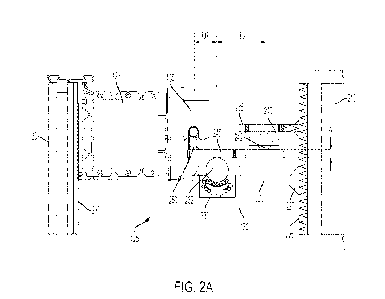
Turning to the embodiment of Figs. 2A-2D, Fig. 2A shows a cross-section of
area 150 in
Fig. 1A along line A-A illustrating a panel mounting system 125 connecting
panel 120, through a
panel transom 123, to a horizontal support element 215 on a module 100, such
as a hollow tube
or wide flange support beam along the top of the module 100 Fig 2D is a
perspective view of
the bracket assembly in Fig. 2A. Fig. 2B is an exploded perspective view of
the components of
the bracket assembly 130. Fig. 2C is an exploded perspective view of the
components of the
hook assembly 135.
With reference to Figs. 2A and 2B, bracket assembly 130 comprises a vertical
support
225 such as a vertical plate that can be mounted to the building support
member 215, such as by
bolting or welding it in place. A lower bearing support 220 extends outwards
from the vertical
support 225. One or more upward facing bearing assemblies 230 are mounted in
the lower
bearing support 220 so that bearing 232 in each bearing assembly 230 projects
over the top
surface 222 of the lower bearing support 220 adjacent the bearing assembly
230. An upper
bearing support 235 extends outwards from the vertical support 225 above the
lower bearing
support 220. One or more downward facing bearing assemblies 240 are mounted in
the lower
bearing support 220 so that the bearing 242 in each bearing assembly 240
projects below the
lower surface 236 of the upper bearing support 235 adjacent the bearing
assembly 240.
There a variety of ways in which the lower bearing support 220 and upper
bearing
supports 235 can be connected to the vertical support 225. One or both of
these components can
be integrally formed with the vertical support 225, such as by casting and/or
machining.
Alternatively, one or both of the upper and lower bearing supports 220, 235
can be formed
separately and then secured to the vertical support 225 using various means
known to those of
skill in the art. For example, a portion of a support plate can engage an
aperture in the vertical
11
CA 03191290 2023- 2- 28
WO 2022/056534
PCT/US2021/071403
plate, such as rearward tabs 221 on lower bearing support 220 that engage
apertures 226. The
parts can then be welded in place. Fillet welds 227, as shown in Fig. 2A, and
additional supports
can be used above and below a bearing support to provide further rigidity and
strength to the
connection. Alternatively, a support plate can be formed in a T shape and
bolted to the vertical
support 225, such as shown in Fig. 28 for upper bearing support 235. While the
vertical support
225 is shown as a plate that can be connected to a horizontal support
structure, e.g., in a module
100 or other building structure, the vertical support 225 could alternatively
be a section of the
horizontal building support itself so that the upper and lower bearing
supports 220, 235 are
directly connected to the relevant horizontal support instead of being
connected to an
intermediate component that itself is connected to the horizontal support.
An anchor plate 245 is provided with a panel coupler to which a mating
component
attached to the panel can couple to thereby attach the panel to the anchor
plate. As shown in this
embodiment, the panel coupler comprises a panel hook support portion 250 near
the front end of
the anchor plate 245 and on which the hook assembly 135 can hang. Other panel
coupler and
mating components can be used. An alternative arrangement is discussed further
below with
respect to Figs. 9A-9F. In the illustrated embodiment, support portion 250
comprises a wall 255
extending vertically upwards from the anchor plate 245 and that has a curved
top edge 260 that
can be shaped to substantially match the shape of at least part of the hook
assembly throat 271
which will rest on it. In an alternative embodiment, in stead of an upward
wall 255, anchor plate
245 can be formed with a lateral slot or groove along its front end that can
receive the end of the
hook and the throat of the hook will engage the forward end of the anchor
plate itself
Any suitable hook assembly 135 can be used on the panel 120 to couple it to
the bracket
assembly 130. One example of a hook assembly 135 is shown in Fig. 2C and
comprises one or
more hooks 270 each having a throat 271 and that is slidably engaged with a
knuckle 272 that
can be mounted to the rear surface 140 of the panel frame. The vertical
position of the hook 270
can be adjusted by a screw mechanism 273. One or more set screws can be used
to lock the
hook 270 in place within knuckle 272. Two or more hook assemblies 135 can be
positioned
adjacent each other to engage the same support portion 250.
Returning to Figs. 2A and 2B, anchor plate 245 is fitted between the lower and
upper
bearings 232, 242. In an embodiment, at least a rear portion 246 of anchor
plate 245 is
12
CA 03191290 2023- 2- 28
WO 2022/056534
PCT/US2021/071403
substantially planar with a thickness W between top and bottom surfaces of
rear portion 246.
The vertical distance between the top of the lower bearing(s) 232 and the
bottom of the upper
bearing(s) 242 is approximately W so that the anchor plate 245 can sit
substantially horizontally
between the lower and upper bearings 232, 242. The particular thickness W is
dependent on
various factors, including the overall weight the mounting assembly 125 is
engineered to
support.
When a panel is hung from the support portion 250, the anchor plate 245 acts
as a lever
arm to transfer the weight of panel to the vertical support 225 with the point
of contact between
the anchor plate 245 and the lower bearing(s) 232 acting as a fulcrum. The
upper bearing(s) 242
keeps the back end of the anchor plate 245 from rotating away from the module
structure.
Advantageously, since all of the panel weight applied to the support portion
250 is transferred
through the bearing system, the position of the anchor plate 245 in the X/Y
plane can be easily
adjusted and without suffering from the friction limitations present in
conventional panel
mounting and support brackets even when the mounting system 125 is fully
loaded.
As shown in Fig. 2A, the distance DI between the fulcrum and the support
portion 250
can be less than the distance D2 between the fulcrum and the point of contact
of the anchor plate
245 with the upper bearing(s) 242 so that most of the panel weight is
transferred through the
fulcrum and the lower bearing support 220. For example, in the embodiment
shown in Fig. 2A,
D2 is about 1.5x Dl. As a result, the upper bearing support 245 and upper
bearing assembly
240 do not need to be as robustly engineered (thus decreasing weight and
expense) as the lower
bearing support 220 and lower bearing assembly 230
The bearing assemblies 230, 240 should be appropriately heavy duty bearing
assemblies
each configured to support at least the maximum expected static load from the
panel with
appropriate safety factors added in The anticipated static load on each
bearing assembly can be
calculated based on the maximum weight of the panel 120, the geometry of the
anchor plate 245,
and the number of lower and upper bearing assemblies used.
In a particular embodiment, the system is designed to support a panel having a
maximum
weight of about 1.5 tons and has two lower bearing assemblies 230 positioned
in the lower
bearing support 220 and one upper bearing assembly 240 in the upper bearing
support 235
13
CA 03191290 2023- 2- 28
WO 2022/056534
PCT/US2021/071403
providing three points of contact to stabilize the anchor plate 245. A
suitable bearing assemblies
for this particular configuration is an Omnitrak TM 9341 heavy duty ball
transfer unit.
Because of the large amount of force applied at the point of contact between
the bearings
232, 242 and a loaded anchor plate 245, some engraving of the anchor plate
surface may occur if
the anchor plate 245 is made with conventional (soft) structural steel. Such
engravings could
make it more difficult to adjust the position of the loaded anchor plate 245.
To address this,
anchor plate 245 can be made of tempered steel or include tempered steel
inserts, such as pucks
or disks, added in the areas around the bearing points of contact (not shown).
Bearing assemblies 230, 240 in the illustrated embodiment have spherical
bearings to
support the anchor plate 245 thereby allowing the anchor plate 245 to move
along both
horizontal axes In an alternative embodiment where adjustment of the anchor
plate 245 along
only a single axis is needed, the bearings 232, 242 could be cylindrical to
allow movement of the
anchor plate in a direction perpendicular to the axis of the cylindrical
bearing.
During production of a prefabricated building module, the bracket assembly 130
can be
attached to the chassis and a panel with corresponding hook assembly 135 hung
therefrom prior
to delivery of the module 100 to a building site. The anchor plate 245 can be
positioned in an
initial position on the bracket, locked in place for transport, and then
unlocked for installation
When unlocked the anchor plate can be moved freely horizontally a relatively
large amount
relative to the final placement tolerance of the panel, such as between 8-
10mm. This allows the
panel position to be adjusted so as to absorb the larger installation
tolerances of initial placement
of the module 100 before it is fully lowered into place. As discussed in more
detail below, an
additional mullion guide system can be provided on left and right panel sides
to automatically
adjust the position of a panel being lowered relative to an already placed
panel to achieve second
smaller placement tolerance, such between 1-3mm, that may be required by other
interacting
structures on adjacent sides of the panel. Advantageously, and particularly
when used in
conjunction with a panel guide system that positions the panel as the module
100 is placed, the
anchor plate 245 will automatically adjust as the module 100 and attached
panel 120 is lowered
into position and the mullion system provides for further adjustment. After
final placement of
the panel on site, a worker can easily fix the anchor plate 245 in position on
the bracket to
thereby lock the panel's position.
14
CA 03191290 2023- 2- 28
WO 2022/056534
PCT/US2021/071403
Turning to Fig. 2B and 2D, one or more locking blocks 275 are mounted on the
top
surface of 222 of the lower bearing support 220. For example, two locking
blocks 275 can be
provided and mounted on the left and right sides of the lower bearing support
220 with the
upward facing hearing assemblies 230 in between The locking blocks 275 are
configured so that
they have only minimal effect, if any, with the movement of the anchor plate
245 between the
bearings 232, 242. With a generally planar anchor plate 245, the top surface
of the locking block
275 should have a height above the top surface 222 of the lower bearing
support 220 that is
lower than the height of the bearing 232 above the anchor plate so that the
anchor plate 245 is
supported by the bearings and rides at least slightly above the locking blocks
275. Locking
block 275 can be formed separately from the lower bearing support 220 and
attached thereto
using conventional means, such as bolts and/or welding. Alternatively, locking
block 275 could
be integrally formed with the lower bearing support 220.
Locking blocks 275 each have a respective first aperture 276 that is
configured to receive
the shaft of a bolt 280 Corresponding adjustment apertures 278 are provided in
the anchor plate
245 and positioned so that when the anchor plate 45 is placed over the lower
support 220, the
first apertures 276 are accessible through the adjustment aperture 278. The
diameter of the
adjustment aperture 278 is selected so that when bolt 280 is mounted in the
first aperture 276 the
anchor plate 245 has a maximum horizontal range of motion of at least the
desired adjustment
amount.
To initially secure the anchor plate 245 in position for transport a locking
bolt (threaded
or unthreaded) or similar component 285 can be passed through aperture 284 in
the locking plate
245 and into corresponding aperture 282 in the locking block. Prior to
installation of the module
100 with mounted panel 120 the locking bolt is 285 is removed so the anchor
plate 245 can be
adjusted.
Once the panel is properly positioned and aligned on a building, a locking set
screw 289
(which can be the same or different from the locking bolt 285) is screwed into
threaded aperture
286 in the anchor plate so that its leading end engages the top surface of the
locking block 275
beneath the aperture 286. When screwed in tightly, friction between the
leading end of bolt 289
and the locking block 275 will inhibit motion of the locking plate 245
relative to the support
plate 220. Preferably the aperture 286 is positioned and locking block 275
configured so that the
CA 03191290 2023- 2- 28
WO 2022/056534
PCT/US2021/071403
aperture 286 will be above the locking block 275 throughout the entire
adjustment range of the
locking plate 245. Aperture 286 is also preferably displaced from aperture 285
an amount
greater than the adjustment range of the locking plate 245 to avoid the
possibility of aperture 276
in the locking block 275 being exposed through aperture 286 in the locking
plate 245, which
situation may interfere with the ability of the locking plate 245 to be
securely locked in an
adjusted position.
Turning to Figs. 9A-9F there is shown another embodiment of a bracket assembly
900
that can be used in a panel mounting system as discussed herein. Fig. 9A is a
cross-section view
of panel mounting system with the bracket assembly 900. Fig. 9B is a partial
exploded view of
the bracket assembly of Fig. 9A. This embodiment can be used in the same
general manner as
discussed above generally and with reference to the embodiment of Figs. 2A-2D
and designed to
meet the same general specifications.
With reference to Figs. 9A and 9B, bracket assembly 900 comprises a horizontal
support
plate 902 that is configured to be rigidly connected to building support
structures 215 at a rear
portion of the support plate 902. A variety of means known to those of skill
in the art can be
used to connect the horizontal support plate 902 to a building support
structure 215, such as
those discussed above with respect to bracket assembly 130 and connection of
the lower support
plate 220 to vertical support 225.
A bearing support 904 has a downward facing bearing assembly 906 mounted in
it. A
portion of the rolling bearing 907 in bearing assembly 906 (See Fig. 9C)
extends downward past
lower surface 905 of the bearing support 904. The bearing support 904 is
mounted over the
support plate 902 so that the rolling bearing engages the top surface 903 of
the support plate.
The front of the bearing support 904 has an outward facing panel coupler 908
from which a
panel can be hung. As noted, any suitable panel coupler can be used.
Fig. 9C is an exploded view of the bearing support 904. In the illustrated
embodiment, a
main body 920 has a vertical aperture 922. Bearing assembly 906 is mounted to
a cap 924, such
as with bolt 926 that engages a rod 928 of the bearing assembly. Bearing
assembly 906 is fitted
into aperture 922 and the cap 924 is affixed to the main body 920, such as
with screws.
Alternative ways of mounting the bearing support 904 to the main body 920
known to those of
skill in the art can also be used.
16
CA 03191290 2023- 2- 28
WO 2022/056534
PCT/US2021/071403
A pair of horizontal flange portions 930 extend outwards from the bottom of
the bearing
support. In the illustrated embodiment, the main body 920 is fitted between
and attached to
vertical members 932 extending upwards from a base plate 934. The bottom of
the base plate
934 forms the lower surface 905. The base plate extends horizontally from the
vertical members
932 to form flange portions 930. Base plate 934 has a central aperture 936
through which
through which portion of the rolling bearing 907 in bearing assembly 906
extends. While main
body 920 and the base plate 934 that forms the flanges 930 are shown as
separate components,
flanges 934 can be integrally formed with body 920 or connected in other
manners
Figs. 9D and 9E illustrate the mounting of bearing assembly 904 to the support
plate 902.
Bearing assembly 904 is positioned over the support plate 902 with the roller
bearing 907 in
contact with the upper surface 903 of the support plate 902 and with the lower
surface 905 of the
bearing assembly 904 spaced apart from the upper surface 903 of the support
plate 902. Because
of the large amount of force applied at the point of contact between roller
bearing 907 and the
upper surface 903 when a panel is mounted to the bearing assembly, some
engraving of the
support plate 902 may occur if it is made with conventional (soft) structural
steel. Such
engravings could make it more difficult to adjust the position of the loaded
bearing assembly
904 To address this, the support plate 902 can be made of tempered
steel or include tempered
steel insert 944 in the areas around the bearing point of contact.
Each of the flanges 930 has an aperture 940 formed therein. The bearing
assembly 904 is
positioned so apertures 940 are aligned with apertures 942 formed in the
support plate 902. For
each flange 930, a bolt 950 is passed through the respective aperture 940 and
into the respective
aperture 942 in the support plate. The bolt 950 can be affixed to the support
plate at aperture
942. A lower plate 946 can be provided beneath the support plate 902 and the
bolts pass through
apertures 942 and engage respective apertures 948 in the lower plate 946. In
an embodiment, the
bolts 950 threadedly engage the apertures 948 in the lower plate 946 and may
also threadedly
engage the apertures 942 in the support plate 902.
The horizontal range of motion of the bearing assembly 904 relative to support
plate 902
is constrained by the by the bolts 950 interacting with the inner periphery of
the apertures 940.
As discussed above, the relative dimensions of the bolts and apertures can be
selected to restrict
17
CA 03191290 2023- 2- 28
WO 2022/056534
PCT/US2021/071403
horizontal motion to a desired maximum offset, such as an offset commensurate
with the panel
placement tolerance.
The heads 952 of the bolt have a diameter greater than the diameter of
aperture 940 or a
washer with a diameter greater than aperture 940 is placed on the bolt. The
bolts 950 directly or
via the washers 954 restricts the ability of each flange 930 to move upwards
away from the
support plate 902 and thereby restricts the range that the bearing support 904
can tilt relative to
support plate 902 even when the load applied to the bearing support is not
fully normal and a
torque is introduced. The extent to which the rolling bearing 907 extends
beyond the bottom
surface 905 of the bearing support 904 and the tightness of the bolts can be
selected to limit the
range of tilt to a small enough amount to prevent the lower surface 905 of
bearing assembly 904
from contacting the support plate 903 and allow substantially all of the load
placed on the
bearing support 904, e.g., by a mounted panel, to be transferred to the
support plate 902 by the
rolling bearing 907. For example, when the bolts 950 are provided with washers
954, the bolts
can be tightened so that the head of the bolt holds the washer loosely against
the respective
flange 930 while allowing minimal vertical play.
The front of the bearing support 904 has an outward facing panel coupler 908
from which
a panel can be hung. As noted, various panel coupler configurations can be
used. In the
illustrated embodiment, and with further reference to Fig. 9F, panel coupler
908 has a vertical
track 910, such as a T-Track. A mating component 912 is attached to the panel,
such as on
transom portion 123. Mating component 122 has a correspondingly shaped
extension 914, such
as one having a T-shaped cross section. To mount the panel to the bearing
support, the extension
914 is fitted into track 910 and secured in place, for example with a bolt 916
that passes through
the cap 924 and threadedly engages aperture 960 in extension 914. Mating
component 912 can
be movably mounted to the panel. In an embodiment, mating component 912 is
mounted to one
or more horizontal bars 962 that slidably engage corresponding slots in the
transom portion 123.
When a panel is mounted to the panel coupler the load from the panel is
transferred from
the bearing support through the bearing to the support plate. The bearing
support can be locked
in a default position, e.g., for transport, relative to the support plate by
use of a locking pin. The
locking pin can be removed before installation. Various locking pin
configurations can be used.
For example an additional aperture can be formed in one or both of the tabs
930 and a locking
18
CA 03191290 2023- 2- 28
WO 2022/056534
PCT/US2021/071403
pin passed through such an aperture to engage a corresponding aperture in the
support plate 902.
(Not shown).
When a module 100 having a panel 120 hung from a bracket assembly mounted to
the
module is moved, such as when the module 100 is lifted by a crane at a
building site, the lower
part of the panel will tend to swing towards and away from the wall on which
it is mounted. To
address this, elastic spacer assemblies 305 can be mounted between a lower
support of a panel
and an opposing structure on the outward face of chassis 102 of a module 100.
Fig. 3A is a cross section view of panel 120 attached using a bracket and hook
assembly
130, 135 as discussed above. One or more elastic spacer assemblies 305 are
connected between
a bottom horizontal support 310 of the panel 120 and a suitably structural
feature of on the
module 100, such as a horizontal support member 315 at a bottom of a module
chassis Elastic
spacer assembly 305 allows some movement of the bottom of the panel 120
relative to the
chassis 102 while preventing the panel 120 from swinging freely. For example,
the elastic
spacer assembly 305 can be configured to urge the bottom of the panel 120 to a
set position
relative to the chassis 102 while allowing the panel 120 to swing in and out a
predefined
distance.
Fig. 3B is an illustration of one embodiment of an elastic spacer assembly
305. The
spacer assembly 305 comprises a compression spring 320, a tension spring 325,
and a distance
limiter 330. The components 320, 325, 330 are connected at an outer end to a
first bracket 335
that is attached to the support 310 on the panel. The inner end of components
320, 325, 330 are
connected to a second bracket 340 that is attached to the horizontal support
315 on the chassis
102. The brackets 335, 340 can be attached to their respective supports using
conventional
means, such as by welding, bolts, or other means known to those of skill in
the art. While the
spacer assembly 305 is shown as being attached to horizontal supports, they
can alternatively be
connected to any suitable support member on the panel 120 and chassis 102. In
the illustrated
embodiment, brackets 335 and 340 are L and U shaped, respectively. Alternative
configurations
can be used.
There are various structures used to align a panel being installed relative to
one already in
place. Fig. 8 shows atop¨down view of a junction between two adjacent panels
800a, 800b with
a conventional panel alignment system. A first pair of alignment flanges 820
extend outward
19
CA 03191290 2023- 2- 28
WO 2022/056534
PCT/US2021/071403
from the side 810a of the first panel 800a. A second pair of alignment flanges
830 extend
outwards from the adjacent side 810b of the second panel 800b. The pairs of
flanges 820, 830
can be affixed to the respective panel sides 810a, 810b by various means and
can extend
substantially the entire vertical length of the panel sides 810a, 810b. The
pairs of flanges 820,
830 are positioned on the respective panel sides 810a, 810b so that when the
panels 800a, 800b
are aligned to be substantially co-planar, one pair of flanges will engage the
other to help lock
the position of the panel sides 810a, 820b in position. In the illustration of
Fig. 8, one pair of
flanges 830 fits between the other pair 820.
Panels generally need to be placed to a high degree of accuracy and an
alignment system
such as in Fig. 8 can require very tight placement tolerances, such as between
1-3 mm, for the
pairs of alignment flanges to properly mate. Other interacting structures on
adjacent panel sides
may also require tight placement tolerances. As will be appreciated, when
lowering panels into
position on a building achieving such a tight placement tolerance can be
difficult. When the
panel is pre-attached to a prefabricated building module, the initial module
placement relative to
a previously placed neighbor module may only be within a larger horizontal
placement tolerance,
such as lOmm, as the module is lowered into place. This tolerance is
insufficient for proper
mating of adjacent panels.
According to a further aspect of the invention, a panel guide system is
provided which
operates to automatically adjust alignment of a panel being lowered into place
from a first large
alignment tolerance, such as lOmm, down to a second much tighter tolerance,
such as 1-3mm, as
the panel being lowered begins to interact with a previously placed panel.
Turning to Figs. 4A ¨
4E there is shown a panel guide system 400 which can be used in connection
with the panel
mounting system 125 addressed herein. Fig. 4A is a front perspective view of a
panel 120
mounted to a module chassis 102illustating the placement of mullion guides
405, 410 and
upward facing alignment pin 415. Fig. 4B is atop perspective view of the
configuration of Fig.
4A showing the right mullion guide 410 and top of the panel 120. Fig. 4C is a
bottom
perspective view of the configuration of Fig. 4A showing the right mullion
guide 410 and bottom
of the panel 120. Figs. 4D and 4E are similar respective top and bottom
perspective views
showing the left mullion guide 405.
CA 03191290 2023- 2- 28
WO 2022/056534
PCT/US2021/071403
The panel guide system 400 comprises left and right mullion guides 405, 410
configured
to interlock and operative to self-align a side of panel being lowered in
place (in combination
with a module 100 or as a discrete component) with the adjacent side of an
already placed panel.
The mullion guides 405, 410 can he positioned on the vertical sides of the
panels and can work
in conjunction with conventional tight-tolerance alignment components. In the
illustrated
embodiment, mullion guides 405, 410 are positioned between respective pairs of
alignment
flanges 445, 450. An alignment pin 415 and alignment aperture 420 can be
provided further
align the free side of the panel being placed as it is lowered into its final
position.
As discussed more fully below, and with further reference to Fig. 1A, the
mullion guides
405, 410 are can be configured so the top of the mullion guide 410 on the
leading side of an
already placed first panel 120b extends above the top of that panel and has a
first alignment
mechanism formed in that extension. The mullion guide 405 on the adjacent side
of the panel
being placed 120a has a second alignment mechanism formed at the bottom of
guide 405 near a
corner of the panel 120a As panel 120a is lowered into place, the first
alignment mechanism at
the top of mullion guide 410 engages mullion guide 405 and operates to align
mullion guide 405
in a first horizontal direction, such as substantially normal to the plane of
the panel 120b (e.g.,
inward and outward from the building) The second alignment mechanism at the
bottom of
mullion guide 405 engages mullion guide 410 and operates to align mullion
guide 405 in a
second horizontal direction substantially orthogonal to the first direction,
such as substantially
parallel to the plane of the panel 120b (e.g., left and right along the face
of the building). The
first and second alignment mechanisms can be configured to bring the placement
tolerance of the
panel being lowered from a large initial tolerance, such as 10 mm, to a
tighter tolerance needed
for other interlocking components on the adjacent panel sides, such as flange
pairs 445, 450 with
a tolerance of 1-3mm, before the panel is lowered to the point that such other
interlocking
components interact.
As the bottom of panel 120a gets near the top of the lower panel 120c, the
alignment
aperture 420 on the bottom of the panel 120a mates with the corresponding
alignment pin 415 on
the top of the lower panel 120c attached to the module 100c on which the
module being placed
100a will rest to align the free side of the panel 120a. After module 100a is
fully seated and the
21
CA 03191290 2023- 2- 28
WO 2022/056534
PCT/US2021/071403
panel 120a aligned, the position of the panel 120a can be locked in place, for
example by locking
supporting bracket assemblies 135 as discussed above.
For the initially placed module 100 in a row, such as modules 100b and 100d in
Fig 1A, a
mullion guide is only needed on the leading edge of the panel 120 where a next
panel will
couple. In addition, the panels on such modules, such as panels 120b and 120d,
can be fitted
with both a left and a right upward facing alignment pin 415. The pair of
alignment pins 415 are
used to align the panel 120 on the next vertically stacked initial row module
100 in lieu of
aligning a panel edge with the adjacent edge of the previously placed
horizontal panel. Thus,
panel 120d will have left and right alignment pins 415 and these are used to
align the base of the
panel 120d when module 100b is put in place on top of module 100d.
The mullion guides 405, 410 can be removable allowing them to be easily
mounted on
the proper panel sides for left-to-right or right-to-left installation. In
addition, mullion guides
405, 410 can be configured to allow removal after serving their panel
alignment function. Once
removed, mullion guides 405, 410 can be installed on other panels. The
alignment pins 415 can
also be removable and configured to attach to a left or right alignment pin
mounting 416 so that
the alignment pin 415 can be easily mounted on the appropriate left or right
position on top of
the panel 120. In one configuration, and as shown in Fig. 4F, alignment pin
415 can extend
upward from a base plate 416 which can be mounted to a guide pin plate 417
affixed or formed
on the top edge of the panel 120 in the appropriate location. Other mechanisms
for mounting the
alignment pin 415 can alternatively be used
Fig. 5A is a side view of a top portion 508 of right mullion guide 410 with a
first
alignment mechanism. Fig. 5B is a cross-section view of right mullion guide
410 through line B-
B. Turning to Figs. 5A and 5B, right mullion guide 410 is a generally
elongated member having
a main body with a back wall 501 which can be attached to the side of a panel
120. Opposing
side walls 502 extend outward from the back wall 501. Opposed flange walls 504
extend from
the respective side walls 502 towards each other. The flange walls 504 define
an intermediate
channel 506. Additional extensions 507 of the side walls 502 can be formed
outward of the
flange walls 504. At the top portion 508 of the mullion guide 410 the inward
length of the flange
walls 504 from the side walls 102 decreases so that intermediate channel 506
opens up to form a
funnel shaped channel portion 510 at the upper end of the channel 506. As
discussed further
22
CA 03191290 2023- 2- 28
WO 2022/056534
PCT/US2021/071403
below, the funnel portion 510 is operative to capture a portion of the mullion
guide 405 and align
it within the channel 506 as the mullion guide 405 is lowered past the top 508
of mullion guide
410.
Fig. 5C is a side view of the left mullion guide 405. Fig. 5D is a cross-
section view of
left mullion guide 405 through line C-C. Left mullion guide 405 has an
elongated body
comprising elongated wall 516. When the mullion guide 504 is installed on the
side of a panel
120, wall 516 will extend outwards from the side of the panel and be generally
parallel to a plane
defined by the front face of that panel. 120. In the illustrated embodiment,
the left mullion
guide 504 has a generally T shaped cross-section along its length where the
wall 516 forms the
stem of the T and extends outwards substantially perpendicularly to the top
portion of the T 514.
The second alignment mechanism comprises at least one guide 520 positioned on
the
wall 516 at or near the bottom of 517 of mullion guide 405. In the embodiment
illustrated, there
is a guide 520 on opposing sides of wall 516. Each alignment guide 520 is
configured to define a
tapered channel 522 narrowing upwards along the vertical axis of the mullion
guide 405In the
illustrated embodiment, each alignment guide 520 comprises first and second
wedge shaped
blocks 520a, 520b which are affixed to the sides of the wall 516 as
illustrated. Blocks 520a,
520b can be symmetric, such as triangular, or differently shaped as
illustrated wherein outer
block 520a (furthest from portion 514) is generally triangular while an inner
block 520b is
trapezoidal. Other configurations are possible. While alignment guide 520 is
illustrated as being
formed of separate blocks 520a, 520b, alignment guide could also be a single
integral component
attached to the wall 516. As discussed further below, the tapered channel 522
is operative to
capture a portion of the mullion guide 510 and align it within the channel 522
as the mullion
guide 405 is lowered past the top 508 of mullion guide 410.
The mullion guide 405, 410 can be made of steel or other suitable material.
The setting
blocks 520 on the left mullion guide 405 are preferably made of rigid material
such as plastic, for
example Teflon lm. Other rigid plastics or other materials, including metals,
could be used
instead. It is also possible for setting blocks 520 to be formed integrally
with the mullion guide
405.
The mullion guides 405, 410 can be attached to the side of a panel 120 in a
variety of
ways. A particular mounting arrangement is discussed below. For mullion guides
that are
23
CA 03191290 2023- 2- 28
WO 2022/056534
PCT/US2021/071403
removable after panel placement, suitable attachment points can be provided to
allow use of a
rope or cable to help lift the guides 405, 410 out from between adjacent edges
of placed panels,
such as aperture 511 in guide 410 and aperture 530 in guide 405 (Figs. 5A,
5C).
Fig. 6A shows a broken perspective view of a side of a panel 120 having
mullion guide
405 mounted thereto. Fig. 6B is a horizontal cross section through the setting
blocks 520. In this
embodiment, mullion guide 405 slidably engages a track 605 that is mounted
vertically along the
side of the panel and which can be placed between the pair of alignment
flanges 445. For a T-
shaped mullion guide 405 as shown herein, track 605 can be a C-shaped track
that captures the
anus on the top portion 514 of the T. Depending on the configuration of
mullion guide 405,
different track configurations may be used. A set screw 610 placed in the
track 605 at the bottom
prevents the mullion guide 405 from sliding past it. A locking screw (not
shown) can be used to
fasten the mullion guide 405 at the top of the track 605.
Fig. 6C shows a broken perspective view of a side of a panel 120 having
mullion guide
410 mounted thereto. Fig. 6D is a horizontal cross section through the setting
blocks 520. In
this embodiment, mullion guide 410 slidably engages a track 620 that is
mounted vertically
along the side of the panel and which can be placed between the pair of
alignment flanges 450.
In the disclosed embodiment, track 620 is comprised of a U-shaped channel 622
with a base 625
attached to the side of the panel and arms 630 extending outward therefrom. A
pair ofJ -shaped
channel members 635 are attached inside the arms 630 and configured to capture
the extensions
507 on the mullion guide 410 while the back 501 of mullion guide 410 rides
against the base 625
of the channel 622. While channel members 635 are illustrated as being
separate from the U-
shaped channel 622, other configurations can be used. For example, the outer
ends of channel
622 can be rolled inwards to form a capture area for extension 507. A set
screw (not shown)
placed in the track 620 at the bottom prevents the mullion guide 410 from
sliding past it. A
locking screw (not shown) can be used to fasten the mullion guide 410 at the
top of the track
620. Depending on the configuration of mullion guide 410, different track
configurations may
be used.
As further illustrated in Figs. 7A-7C, the alignment mechanisms on the mullion
guides
405, 410 operate to align mullion guide 405 in the horizontal axes parallel
and perpendicular to
the plane defined by the panel face as each alignment mechanisms interacts
with a portion of the
24
CA 03191290 2023- 2- 28
WO 2022/056534
PCT/US2021/071403
other mullion guide. Figs. 7A and 7B are perspective views of the mullion
guides 405, 410 just
before they interact. Fig. 7C is a cross-section view showing the alignment
mechanism on each
mullion guide fully engaged with the structure of the other mullion guide.
With reference to
these figures, when a panel, such as panel 120a on module 100a, is lowered
into place, the panel
120a is positioned so that the stem 516 of the left mullion guide 405 will
enter the funnel portion
510 of channel 506 at the top of the right mullion guide 410 which is affixed
to extends above
panel 120b on module 100b. As the panel 120a is further lowered, channel
portion 510 on the
right mullion guide 410 guides stem 516 of the left mullion guide 405 into the
main channel 506
of the right mullion guide 410 thereby automatically aligning the panel 120a
in a front to back
direction. Also as the panel 120a is lowered, the flanges 504 on the right
mullion guide 410 are
captured by alignment guide 520 at the bottom of the left mullion guide 405
which operates to
automatically aligns the bottom of the panel left-to-right as the panel is
further lowered
In a preferred embodiment, the alignment mechanisms on the mullion guides are
configured to accommodate a relatively large placement tolerance of module
100a in its initial
position, such as a tolerance of 10 mm. As a result, so long as the initial
alignment of the
module 100a is within the large design tolerance range, the module can be
lowered and the panel
will automatically align to the smaller tolerance of other panel coupling
features, such as
between 1-3mm. If the panel 120a is mounted to a module using the bracket
assembly 130
discussed above, the anchor p1ate245 will move to accommodate positional
adjustments of the
panel from the larger tolerance range of the initial module placement to the
tighter tolerance
range of other coupling features on the panels. Once the panel is fully
seated, the anchor plate
245 can be locked into position as discussed above.
In addition, once the panel is fully seated the slidably mounted mullion
guides 405, 410
on the adjacent panel edges can be removed from the respective panels. To
accomplish any
locking screw or other locking member used to hold the mullion guides 405, 410
in place are
removed. Such locking members should be positioned at the top of the mullions
in a location
that can be accessed after the panels are positioned. Once the locking members
are removed, the
mullion guides 405, 410 can be pulled upwards in their respective tracks 605,
620, for example
by using ropes or cables attached to the respective apertures 530, and 511 at
the top of mullion
guides 405, 410.
CA 03191290 2023- 2- 28
WO 2022/056534
PCT/US2021/071403
The easy mounting and removability of the mullion guides 405, 410 allows the
mullion
guides to be temporarily installed on the sides of panels and then removed
after the panels have
been placed in the building and reused on other panels. In addition, it is
easy to mount the
mullion guides as appropriate for the direction in which modules / panels are
being placed.
The mullion guides 405, 410 are described herein as left and right mullion
guides for
convenience. The position of guides 405, 410 position on a panel 120 can be
reversed if the
modules 100 are being stacked right to left instead ofleft to right. In such a
case, mullion guide
405 would be attached to the right side of the panel 120 and mullion guide 410
attached to the
left side of the panel 120. The alignment pin 415 would also be mounted on the
left instead.
Panels can be provided with left and right alignment apertures 420 to
accommodate alignment
pins 415 in either location.
While the right and left mullion guides 410, 405 are described herein as
having
particularly structured first and second alignment mechanisms, other
configurations are possible.
For example instead of the alignment mechanism on mullion guide 410 operative
to align
mullion guide 405 front to back while the alignment mechanism on mullion guide
405 is
operative to align it left and right, the alignment mechanisms can be
rearranged to switch the
direction of alignment provided by each.
While the panel guide system 400 as disclosed herein is preferably used in
conjunction
with panels 120 that are pre-mounted to a prefabricated module 100, the guide
system 400 may
also be used on panels that are separately mounted to the exterior of a
building structure, and
whether or not that building is made of prefabricated modules or a
conventional girder
framework. The panel guide system 400 can be used on panels mounted to a
module 100 using
panel mounting system 125 as disclosed herein or with panels mounted to a
module 100 or other
building structure in another manner.
Various aspects, embodiments, and examples of the invention have been
disclosed and
described herein. Modifications, additions and alterations may be made by one
skilled in the art
without departing from the spirit and scope of the invention as defined in the
appended claims.
26
CA 03191290 2023- 2- 28