Note: Descriptions are shown in the official language in which they were submitted.
ERGONOMIC VEHICLE CAB
CROSS-REFERENCE TO RELATED PATENT APPLICATIONS
100011 This application is a continuation in part of U.S. Patent
Application No. 17/987,098,
filed November 15, 2022, which claims the benefit of and priority to U.S.
Provisional Patent
Application No. 63/280,360, filed November 17, 2021, the entire disclosures of
which are hereby
incorporated by reference herein. This application also claims the benefit of
and priority to: (a)
U.S. Provisional Patent Application No. 63/317,322, filed March 7, 2022; (b)
U.S. Provisional
Patent Application No. 63/325,936, filed March 31, 2022; and (c) U.S.
Provisional Patent
Application No. 63/356,106, filed June 28, 2022, the entire disclosures of
which are hereby
incorporated by reference herein.
BACKGROUND
100021 Vocational vehicles typically include a cab that may be coupled to
components, such as
a chassis or an implement.
SUMMARY OF THE INVENTION
100031 At least one embodiment relates to a refuse vehicle that includes a
chassis coupled to a
wheel and having a first portion and a second portion, an energy storage
system supported by the
chassis, a drive motor coupled to the wheel and configured to receive
electrical energy from the
energy storage system and provide rotational mechanical energy to the wheel, a
cab supported by
the first portion of the chassis, a refuse compartment supported by the second
portion of the chassis,
a seat supported within an interior of the cab and including a seat support
and a backrest, a control
console arranged within the interior of the cab and including a joystick, and
a suspension coupled
between the cab and the seat and configured to allow the seat to move relative
to the cab. The
suspension supports the seat and the control console so that a position of the
control console
relative to the seat is maintained.
-1-
8247439
Date recue/Date received 2023-03-06
100041
Another embodiment relates to a refuse vehicle that includes a chassis coupled
to a
wheel and having a first portion and a second portion, an energy storage
system supported by the
chassis, a drive motor coupled to the wheel and configured to receive
electrical energy from the
energy storage system and provide rotational mechanical energy to the wheel, a
cab supported by
the first portion of the chassis, a refuse compartment supported by the second
portion of the chassis,
a seat supported within an interior of the cab and including a seat support
and a backrest, a grab
handle coupled to an interior wall of the cab and arranged laterally outwardly
from the seat, a
suspension coupled between the cab and the seat and configured to allow the
seat to move relative
to the cab, and a control console including a joystick and an arm rest. The
grab handle is arranged
at a height within the interior of the cab that aligns with the seat support
of the seat. The control
console is coupled to the seat and supported by the suspension so that the
control console moves
with the seat as the seat moves relative to the cab.
100051
Another embodiment relates to a refuse vehicle that includes a chassis coupled
to a
wheel and having a first portion and a second portion, an energy storage
system supported by the
chassis, a drive motor coupled to the wheel and configured to receive
electrical energy from the
energy storage system and provide rotational mechanical energy to the wheel, a
cab supported by
the first portion of the chassis, a refuse compai __________________________
intent supported by the second portion of the chassis,
a seat supported within an interior of the cab and including a seat support
and a backrest, a first
grab handle coupled to a rear wall of an interior of the cab and arranged
laterally outwardly from
the seat, a second grab handle coupled to a front wall of the interior of the
cab, a control console
arranged within the interior of the cab and including a joystick, and a
suspension coupled between
the cab and the seat and configured to allow the seat to move relative to the
cab. The second grab
handle is arranged at a height that is greater than a height of the first grab
handle. The suspension
supports the seat and the control console so that a position of the control
console relative to the
seat is maintained.
100061
This summary is illustrative only and is not intended to be in any way
limiting. Other
aspects, inventive features, and advantages of the devices or processes
described herein will
-2-
8247439
Date recue/Date received 2023-03-06
become apparent in the detailed description set forth herein, taken in
conjunction with the
accompanying figures, wherein like reference numerals refer to like elements.
BRIEF DESCRIPTION OF THE DRAWINGS
100071 The disclosure will become more fully understood from the following
detailed
description, taken in conjunction with the accompanying figures, wherein like
reference numerals
refer to like elements, in which:
100081 FIG. 1 is a left side view of a vehicle, according to an exemplary
embodiment;
100091 FIG. 2 is a perspective view of a chassis of the vehicle of FIG. 1,
according to an
exemplary embodiment;
100101 FIG. 3 is a perspective view of the vehicle of FIG. 1 configured as
a front-loading refuse
vehicle, according to an exemplary embodiment;
100111 FIG. 4 is a left side view of the front-loading refuse vehicle of
FIG. 3 configured with a
tag axle;
100121 FIG. 5 is a perspective view of the vehicle of FIG. 1 configured as
a side-loading refuse
vehicle, according to an exemplary embodiment;
100131 FIG. 6 is a right side view of the side-loading refuse vehicle of
FIG. 5;
100141 FIG. 7 is a top view of the side-loading refuse vehicle of FIG. 5;
100151 FIG. 8 is a left side view of the side-loading refuse vehicle of
FIG. 5 configured with a
tag axle;
100161 FIG. 9 is a perspective view of the vehicle of FIG. 1 configured as
a mixer vehicle,
according to an exemplary embodiment;
-3-
8247439
Date recue/Date received 2023-03-06
100171 FIG. 10 is a perspective view of the vehicle of FIG. 1 configured as
a fire fighting
vehicle, according to an exemplary embodiment;
100181 FIG. 11 is a left side view of the vehicle of FIG. 1 configured as
an airport fire fighting
vehicle, according to an exemplary embodiment;
100191 FIG. 12 is a perspective view of the vehicle of FIG. 1 configured as
a boom lift,
according to an exemplary embodiment;
100201 FIG. 13 is a perspective view of the vehicle of FIG. 1 configured as
a scissor lift,
according to an exemplary embodiment;
100211 FIG. 14 is a perspective view of a chassis of the vehicle of FIG. 1,
according to an
exemplary embodiment;
100221 FIG. 15 is a perspective view of a chassis of the vehicle of FIG. 1,
according to an
exemplary embodiment;
100231 FIG. 16 is a top view of an interior of a cab of the vehicle of FIG.
1, according to an
exemplary embodiment;
100241 FIG. 17 is a perspective view of the interior of the cab of FIG. 16;
100251 FIG. 18 is a cross-sectional view of the interior of the cab of the
vehicle of FIG. 1,
according to an exemplary embodiment;
100261 FIG. 19 is a side view of the interior of the cab of the vehicle of
FIG. 16, according to
an exemplary embodiment;
100271 FIG. 20 is a side view of the interior of the cab of the vehicle of
FIG. 16, according to
an exemplary embodiment;
100281 FIG. 21 is a perspective view of the cab of the vehicle of FIG. 1,
according to an
exemplary embodiment;
-4-
8247439
Date recue/Date received 2023-03-06
100291 FIG. 22 is a side view of the interior of the cab of the vehicle of
FIG. 19 configured with
a grab bar, according to an exemplary embodiment;
100301 FIG. 23 is a side view of the interior of the cab of the vehicle of
FIG. 22 configured with
a second grab bar, according to an exemplary embodiment;
100311 FIG. 24 is a top perspective view of an interior of the cab of the
vehicle of FIG. 1
configured with a control console, according to an exemplary embodiment;
100321 FIG. 25 is a schematic illustration of the cab of FIG. 24 with a
suspension coupled to a
seat and a control console, according to an exemplary embodiment;
100331 FIG. 26 is a schematic illustration of the cab of FIG. 24 with a
suspension coupled to a
seat and a control console coupled to the seat, according to an exemplary
embodiment;
100341 FIG. 27 is a top perspective view of the interior of the cab of FIG.
24 configured with a
second control console, according to an exemplary embodiment;
100351 FIG. 28 is a schematic illustration of a controller of the vehicle
of FIG. 1, according to
an exemplary embodiment;
100361 FIG. 29 is a top perspective view of an armrest adjustment assembly
coupled to an
armrest within the cab of FIG. 24 or FIG. 27, according to an exemplary
embodiment;
100371 FIG. 30 is a bottom perspective view of the armrest adjustment
assembly of FIG. 29;
100381 FIG. 31 is a top view of the armrest adjustment assembly of FIG. 29;
100391 FIG. 32 is a bottom view of the armrest adjustment assembly of FIG.
29;
100401 FIG. 33 is an enlarged view of a joint and bracket of the armrest
adjustment assembly
of FIG. 29;
-5-
8247439
Date recue/Date received 2023-03-06
100411 FIG. 34 is a schematic illustration of a side view of the armrest of
FIG. 29 arranged
within the cab of FIG. 24 or FIG. 27 with the armrest in an operating
position;
100421 FIG. 35 is a schematic illustration of a side view of the armrest of
FIG. 29 arranged
within the cab of FIG. 24 or FIG. 27 with the armrest in an stowed position;
100431 FIG. 36 is a top, rear perspective view of a cab of the vehicle of
FIG. 1 in a left-hand
drive configuration, according to an exemplary embodiment;
100441 FIG. 37 is a front view of the cab of FIG. 36;
100451 FIG. 38 is atop, front perspective view of the cab of FIG. 36;
100461 FIG. 39 is top, rear perspective view of a cab of the vehicle of
FIG. 1 in a dual-drive
configuration, according to an exemplary embodiment;
100471 FIG. 40 is a front view of the cab of FIG. 39;
100481 FIG. 41 is atop, front perspective view of the cab of FIG. 39;
100491 FIG. 42 is a top, rear perspective view of a cab of the vehicle of
FIG. 1 in a right-hand
drive configuration;
100501 FIG. 43 is a front view of the cab of FIG. 42;
100511 FIG. 44 is a top, front perspective view of the cab of FIG. 42;
100521 FIG. 45 is atop, front, left perspective view of a dash pod of the
cab of FIG. 36, 39, or
42, according to an exemplary embodiment;
100531 FIG. 46 is a bottom, rear, right perspective view of the dash pod of
FIG. 45; and
100541 FIG. 47 is atop view of the dash pod of FIG. 45.
-6-
8247439
Date recue/Date received 2023-03-06
DETAILED DESCRIPTION
100551 Before turning to the figures, which illustrate certain exemplary
embodiments in detail,
it should be understood that the present disclosure is not limited to the
details or methodology set
forth in the description or illustrated in the figures. It should also be
understood that the
terminology used herein is for the purpose of description only and should not
be regarded as
limiting.
100561 According to an exemplary embodiment, a vocational vehicle (e.g.,
refuse vehicle,
mixing vehicles) includes a cab configured to house an operator and various
systems and controls
of the vocational vehicle. In some embodiments, the cab includes a tunnel that
extends along a
centerline of the cab. The tunnel protrudes into the interior of the cab and
defines a recess on the
exterior of the cab to receive a support structure. In some embodiments, the
support structure is a
chassis. The chassis may include a front portion that is narrower than a rear
portion, such that the
front portion fits within the tunnel of the cab and supports the cab via the
tunnel. In some
embodiments, there are no other devices (e.g., an engine) disposed within the
tunnel. This allows
the tunnel to be lower and allows the cab to sit closer to the ground.
100571 In some embodiments, the size of the tunnel is defined by the
elevation and width of the
chassis. A tunnel with a smaller width allows a seat inside the cab to be
positioned further inboard
within the cab. A shorter tunnel allows a top of the tunnel to be below where
an arm of an operator
would traditionally be. In such an embodiment, the seat can be disposed
directly next to or even
partially above the tunnel and still provide the operator with the necessary
clearances. This allows
the entire cab to be reduced in size (e.g., total volume) since the seats are
disposed closer to the
middle of the cab and the tunnel does not restrict operator clearances.
100581 In another embodiment, the cab includes a multi-step entry. The
multi-step entry may
include a plurality of steps. In one embodiment, the multi-step entry includes
stair-style steps,
where each of the plurality of steps is substantially the same height. In an
exemplary embodiment,
a first step is 15 inches above a ground on which the vehicle travels and a
second step is 15 inches
above the first step. This allows for easier entry and exit for an operator of
the vehicle.
-7-
8247439
Date recue/Date received 2023-03-06
100591 Incorporating the elements of the cab described herein allows the
overall size of the cab
to decrease and improves the ergonomics of the vocational vehicle for an
operator. The cab
described herein provides easier accessibility with lower floor heights, equal
stair heights, a
narrower seating configuration to accommodate a smaller cab, a shorter tunnel
to allow seats to be
positioned more inward in the cab while still maintaining appropriate
clearances for an operator,
and increased visibility with better positioning of the seats and windows of
the cab, among others.
100601 In some embodiments, the cab (e.g., of a refuse vehicle) may be
configured for two
operators (e.g., a left-hand operation and/or a right-hand operation). The
vehicle may include a
controller configured to determine the position and/or presence of an operator
within the cab, and
may configure various settings and controls of the cab and the operation of
the vehicle depending
on such determinations.
100611 In some embodiments, the vehicle (e.g., a refuse vehicle) includes
an armrest and a gas
strut configured to reposition the armrest in a vertical direction. In some
embodiments, the armrest
includes a control console having drive components of the vehicle mounted
thereon (e.g., a
joystick). The armrest is repositionable between an operating position and a
stowed position,
where the armrest pivots between the positions to make the cab a walkthrough
cab. The gas strut
is rigidly coupled to the seat and configured to extend and retract to change
a height of the armrest.
The armrest includes a joint, where the armrest pivots about the joint. The
joint is advantageously
positioned to minimize contact between the armrest and a rear sidewall of the
cab when the armrest
is in the stowed position.
100621 In some embodiments, the vehicle (e.g., a refuse vehicle) includes a
cab that is
selectively configurable in a left-hand drive configuration, a right-hand
drive configuration, and/or
a dual-drive configuration. This modularity in the drive configuration reduces
the number of
unique components that need to be manufactured to produce three different
vehicle drive
configurations. In some embodiments, the cab includes a dash pod that is
installed on both a first
side and a second side of a front console or dash within an interior of the
cab. The dash pod
includes integrated ducting (e.g., one or more ducts for HVAC) and a console
cutout that is
-8-
8247439
Date recue/Date received 2023-03-06
configured to receive either a glove box or an gauge hood (e.g., used on a
steering side). The
console cutout is designed to be universal so that a glove box or gauge hood
can be installed on
either (or both) side of the cab.
Overall Vehicle
100631 Referring to FIGS. 1 and 2, a reconfigurable vehicle (e.g., a
vehicle assembly, a truck,
a vehicle base, etc.) is shown as vehicle 10, according to an exemplary
embodiment. As shown,
the vehicle 10 includes a frame assembly or chassis assembly, shown as chassis
20, that supports
other components of the vehicle 10. The chassis 20 extends longitudinally
along a length of the
vehicle 10, substantially parallel to a primary direction of travel of the
vehicle 10. As shown, the
chassis 20 includes three sections or portions, shown as front section 22,
middle section 24, and
rear section 26. The middle section 24 of the chassis 20 extends between the
front section 22 and
the rear section 26. In some embodiments, the middle section 24 of the chassis
20 couples the
front section 22 to the rear section 26. In other embodiments, the front
section 22 is coupled to
the rear section 26 by another component (e.g., the body of the vehicle 10).
100641 As shown in FIG. 2, the front section 22 includes a pair of frame
portions, frame
members, or frame rails, shown as front rail portion 30 and front rail portion
32. The rear section
26 includes a pair of frame portions, frame members, or frame rails, shown as
rear rail portion 34
and rear rail portion 36. The front rail portion 30 is laterally offset from
the front rail portion 32.
Similarly, the rear rail portion 34 is laterally offset from the rear rail
portion 36. This spacing may
provide frame stiffness and space for vehicle components (e.g., batteries,
motors, axles, gears, etc.)
between the frame rails. In some embodiments, the front rail portions 30 and
32 and the rear rail
portions 34 and 36 extend longitudinally and substantially parallel to one
another. The chassis 20
may include additional structural elements (e.g., cross members that extend
between and couple
the frame rails).
100651 In some embodiments, the front section 22 and the rear section 26
are configured as
separate, discrete subframes (e.g., a front subframe and a rear subframe). In
such embodiments,
the front rail portion 30, the front rail portion 32, the rear rail portion
34, and the rear rail portion
-9-
8247439
Date recue/Date received 2023-03-06
36 are separate, discrete frame rails that are spaced apart from one another.
In some embodiments,
the front section 22 and the rear section 26 are each directly coupled to the
middle section 24 such
that the middle section 24 couples the front section 22 to the rear section
26. Accordingly, the
middle section 24 may include a structural housing or frame. In other
embodiments, the front
section 22, the middle section 24, and the rear section 26 are coupled to one
another by another
component, such as a body of the vehicle 10.
100661 In other embodiments, the front section 22, the middle section 24,
and the rear section
26 are defined by a pair of frame rails that extend continuously along the
entire length of the
vehicle 10. In such an embodiment, the front rail portion 30 and the rear rail
portion 34 would be
front and rear portions of a first frame rail, and the front rail portion 32
and the rear rail portion 36
would be front and rear portions of a second frame rail. In such embodiments,
the middle section
24 would include a center portion of each frame rail.
100671 In some embodiments, the middle section 24 acts as a storage portion
that includes one
or more vehicle components. The middle section 24 may include an enclosure
that contains one
or more vehicle components and/or a frame that supports one or more vehicle
components. By
way of example, the middle section 24 may contain or include one or more
electrical energy
storage devices (e.g., batteries, capacitors, etc.). By way of another
example, the middle section
24 may include fuel tanks fuel tanks. By way of yet another example, the
middle section 24 may
define a void space or storage volume that can be filled by a user.
100681 A cabin, operator compartment, or body component, shown as cab 40, is
coupled to a
front end portion of the chassis 20 (e.g., the front section 22 of the chassis
20). Together, the
chassis 20 and the cab 40 define a front end of the vehicle 10. The cab 40
extends above the
chassis 20. The cab 40 includes an enclosure or main body that defines an
interior volume, shown
as cab interior 42, that is sized to contain one or more operators. The cab 40
also includes one or
more doors 44 that facilitate selective access to the cab interior 42 from
outside of the vehicle 10.
The cab interior 42 contains one or more components that facilitate operation
of the vehicle 10 by
the operator. By way of example, the cab interior 42 may contain components
that facilitate
-10-
8247439
Date recue/Date received 2023-03-06
operator comfort (e.g., seats, seatbelts, etc.), user interface components
that receive inputs from
the operators (e.g., steering wheels, pedals, touch screens, switches,
buttons, levers, etc.), and/or
user interface components that provide information to the operators (e.g.,
lights, gauges, speakers,
etc.). The user interface components within the cab 40 may facilitate operator
control over the
drive components of the vehicle 10 and/or over any implements of the vehicle
10.
100691 The vehicle 10 further includes a series of axle assemblies, shown
as front axle 50 and
rear axles 52. As shown, the vehicle 10 includes one front axle 50 coupled to
the front section 22
of the chassis 20 and two rear axles 52 each coupled to the rear section 26 of
the chassis 20. In
other embodiments, the vehicle 10 includes more or fewer axles. By way of
example, the vehicle
may include a tag axle that may be raised or lowered to accommodate variations
in weight being
carried by the vehicle 10. The front axle 50 and the rear axles 52 each
include a series of tractive
elements (e.g., wheels, treads, etc.), shown as wheel and tire assemblies 54.
The wheel and tire
assemblies 54 are configured to engage a support surface (e.g., roads, the
ground, etc.) to support
and propel the vehicle 10. The front axle 50 and the rear axles may include
steering components
(e.g., steering arms, steering actuators, etc.), suspension components (e.g.,
gas springs, dampeners,
air springs, etc.), power transmission or propulsion components (e.g.,
differentials, drive shafts,
etc.), braking components (e.g., brake actuators, brake pads, brake discs,
brake drums, etc.), and/or
other components that facilitate propulsion or support of the vehicle.
100701 In some embodiments, the vehicle 10 is configured as an electric
vehicle that is
propelled by an electric powertrain system. Referring to FIG. 1, the vehicle
10 includes one or
more electrical energy storage devices (e.g., batteries, capacitors, etc.),
shown as batteries 60. As
shown, the batteries 60 are positioned within the middle section 24 of the
chassis 20. In other
embodiments, the batteries 60 are otherwise positioned throughout the vehicle
10. The vehicle 10
further includes one or more electromagnetic devices or prime movers (e.g.,
motor/generators),
shown as drive motors 62. The drive motors 62 are electrically coupled to the
batteries 60. The
drive motors 62 may be configured to receive electrical energy from the
batteries 60 and provide
rotational mechanical energy to the wheel and tire assemblies 54 to propel the
vehicle 10. The
drive motors 62 may be configured to receive rotational mechanical energy from
the wheel and
-11-
8247439
Date recue/Date received 2023-03-06
tire assemblies 64 and provide electrical energy to the batteries 60,
providing a braking force to
slow the vehicle 10.
100711 The batteries 60 may include one or more rechargeable batteries
(e.g., lithium-ion
batteries, nickel-metal hydride batteries, lithium-ion polymer batteries, lead-
acid batteries, nickel-
cadmium batteries, etc.). The batteries 60 may be charged by one or more
sources of electrical
energy onboard the vehicle 10 (e.g., solar panels, etc.) or separate from the
vehicle 10 (e.g.,
connections to an electrical power grid, a wireless charging system, etc.). As
shown, the drive
motors 62 are positioned within the rear axles 52 (e.g., as part of a combined
axle and motor
assembly). In other embodiments, the drive motors 62 are otherwise positioned
within the vehicle
10.
100721 In other embodiments, the vehicle 10 is configured as a hybrid
vehicle that is propelled
by a hybrid powertrain system (e.g., a diesel/electric hybrid,
gasoline/electric hybrid, natural
gas/electric hybrid, etc.). According to an exemplary embodiment, the hybrid
powertrain system
may include a primary driver (e.g., an engine, a motor, etc.), an energy
generation device (e.g., a
generator, etc.), and/or an energy storage device (e.g., a battery,
capacitors, ultra-capacitors, etc.)
electrically coupled to the energy generation device. The primary driver may
combust fuel (e.g.,
gasoline, diesel, etc.) to provide mechanical energy, which a transmission may
receive and provide
to the axle front axle 50 and/or the rear axles 52 to propel the vehicle 10.
Additionally or
alternatively, the primary driver may provide mechanical energy to the
generator, which converts
the mechanical energy into electrical energy. The electrical energy may be
stored in the energy
storage device (e.g., the batteries 60) in order to later be provided to a
motive driver.
100731 In yet other embodiments, the chassis 20 may further be configured
to support non-
hybrid powertrains. For example, the powertrain system may include a primary
driver that is a
compression-ignition internal combustion engine that utilizes diesel fuel.
100741 Referring to FIG. 1, the vehicle 10 includes a rear assembly,
module, implement, body,
or cargo area, shown as application kit 80. The application kit 80 may include
one or more
implements, vehicle bodies, and/or other components. Although the application
kit 80 is shown
-12-
8247439
Date recue/Date received 2023-03-06
positioned behind the cab 40, in other embodiments the application kit 80
extends forward of the
cab 40. The vehicle 10 may be outfitted with a variety of different
application kits 80 to configure
the vehicle 10 for use in different applications. Accordingly, a common
vehicle 10 can be
configured for a variety of different uses simply by selecting an appropriate
application kit 80. By
way of example, the vehicle 10 may be configured as a refuse vehicle, a
concrete mixer, a fire
fighting vehicle, an airport fire fighting vehicle, a lift device (e.g., a
boom lift, a scissor lift, a
telehandler, a vertical lift, etc.), a crane, a tow truck, a military vehicle,
a delivery vehicle, a mail
vehicle, a boom truck, a plow truck, a fanning machine or vehicle, a
construction machine or
vehicle, a coach bus, a school bus, a semi-truck, a passenger or work vehicle
(e.g., a sedan, a SUV,
a truck, a van, etc.), and/or still another vehicle. FIGS. 3-13 illustrate
various examples of how
the vehicle 10 may be configured for specific applications. Although only a
certain set of vehicle
configurations is shown, it should be understood that the vehicle 10 may be
configured for use in
other applications that are not shown.
100751 The application kit 80 may include various actuators to facilitate
certain functions of the
vehicle 10. By way of example, the application kit 80 may include hydraulic
actuators (e.g.,
hydraulic cylinders, hydraulic motors, etc.), pneumatic actuators (e.g.,
pneumatic cylinders,
pneumatic motors, etc.), and/or electrical actuators (e.g., electric motors,
electric linear actuators,
etc.). The application kit 80 may include components that facilitate operation
of and/or control of
these actuators. By way of example, the application kit 80 may include
hydraulic or pneumatic
components that form a hydraulic or pneumatic circuit (e.g., conduits, valves,
pumps, compressors,
gauges, reservoirs, accumulators, etc.). By way of another example, the
application kit 80 may
include electrical components (e.g., batteries, capacitors, voltage
regulators, motor controllers,
etc.). The actuators may be powered by components of the vehicle 10. By way of
example, the
actuators may be powered by the batteries 60, the drive motors 62, or the
primary driver (e.g.,
through a power take off).
100761 The vehicle 10 generally extends longitudinally from a front side 86
to a rear side 88.
The front side 86 is defined by the cab 40 and/or the chassis. The rear side
88 is defined by the
-13-
8247439
Date recue/Date received 2023-03-06
application kit 80 and/or the chassis 20. The primary, forward direction of
travel of the vehicle 10
is longitudinal, with the front side 86 being arranged forward of the rear
side 88.
A. Front-Loading Refuse Vehicle
100771 Referring now to FIGS. 3 and 4, the vehicle 10 is configured as a
refuse vehicle 100
(e.g., a refuse truck, a garbage truck, a waste collection truck, a sanitation
truck, a recycling truck,
etc.). Specifically, the refuse vehicle 100 is a front-loading refuse vehicle.
In other embodiments,
the refuse vehicle 100 is configured as a rear-loading refuse vehicle or a
front-loading refuse
vehicle. The refuse vehicle 100 may be configured to transport refuse from
various waste
receptacles (e.g., refuse containers) within a municipality to a storage
and/or processing facility
(e.g., a landfill, an incineration facility, a recycling facility, etc.).
100781 FIG. 4 illustrates the refuse vehicle 100 of FIG. 3 configured with
a liftable axle, shown
as tag axle 90, including a pair of wheel and tire assemblies 54. As shown,
the tag axle 90 is
positioned reward of the rear axles 52. The tag axle 90 can be selectively
raised and lowered (e.g.,
by a hydraulic actuator) to selectively engage the wheel and tire assemblies
54 of the tag axle 90
with the ground. The tag axle 90 may be raised to reduce rolling resistance
experienced by the
refuse vehicle 100. The tag axle 90 may be lowered to distribute the loaded
weight of the vehicle
100 across a greater number of a wheel and tire assemblies 54 (e.g., when the
refuse vehicle 100
is loaded with refuse).
100791 As shown in FIGS. 3 and 4, the application kit 80 of the refuse
vehicle 100 includes a
series of panels that form a rear body or container, shown as refuse
compartment 130. The refuse
compatiment 130 may facilitate transporting refuse from various waste
receptacles within a
municipality to a storage and/or a processing facility (e.g., a landfill, an
incineration facility, a
recycling facility, etc.). By way of example, loose refuse may be placed into
the refuse
compaiiment 130 where it may be compacted (e.g., by a packer system within the
refuse
compatiment 130). The refuse compatiment 130 may also provide temporary
storage for refuse
during transport to a waste disposal site and/or a recycling facility. In some
embodiments, the
refuse compaiiment 130 may define a hopper volume 132 and storage volume 134.
In this regard,
-14-
8247439
Date recue/Date received 2023-03-06
refuse may be initially loaded into the hopper volume 132 and later compacted
into the storage
volume 134. As shown, the hopper volume 132 is positioned between the storage
volume 134 and
the cab 40 (e.g., refuse is loaded into a portion of the refuse compartment
130 behind the cab 40
and stored in a portion further toward the rear of the refuse compartment
130). In other
embodiments, the storage volume may be positioned between the hopper volume
and the cab 40
(e.g., in a rear-loading refuse truck, etc.). The application kit 80 of the
refuse vehicle 100 further
includes a pivotable rear portion, shown as tailgate 136, that is pivotally
coupled to the refuse
compatiment 130. The tailgate 136 may be selectively repositionable between a
closed position
and an open position by an actuator (e.g., a hydraulic cylinder, an electric
linear actuator, etc.),
shown as tailgate actuator 138 (e.g., to facilitate emptying the storage
volume).
100801
As shown in FIGS. 3 and 4, the refuse vehicle 100 also includes an implement,
shown
as lift assembly 140, which is a front-loading lift assembly. According to an
exemplary
embodiment, the lift assembly 140 includes a pair of lift arms 142 and a pair
of actuators (e.g.,
hydraulic cylinders, electric linear actuators, etc.), shown as lift arm
actuators 144. The lift arms
142 may be rotatably coupled to the chassis 20 and/or the refuse compai ____
intent 130 on each side of
the refuse vehicle 100 (e.g., through a pivot, a lug, a shaft, etc.), such
that the lift assembly 140
may extend forward relative to the cab 40 (e.g., a front-loading refuse truck,
etc.). In other
embodiments, the lift assembly 140 may extend rearward relative to the
application kit 80 (e.g., a
rear-loading refuse truck). As shown in FIGS. 3 and 4, in an exemplary
embodiment the lift arm
actuators 144 may be positioned such that extension and retraction of the lift
arm actuators 144
rotates the lift arms 142 about an axis extending through the pivot. In this
regard, the lift arms 142
may be rotated by the lift arm actuators 144 to lift a refuse container over
the cab 40. The lift
assembly 140 further includes a pair of interface members, shown as lift forks
146, each pivotally
coupled to a distal end of one of the lift arms 142. The lift forks 146 may be
configured to engage
a refuse container (e.g., a dumpster) to selectively coupled the refuse
container to the lift arms 142.
By way of example, each of the lift forks 146 may be received within a
corresponding pocket
defined by the refuse container. A pair of actuators (e.g., hydraulic
cylinders, electric linear
actuators, etc.), shown as articulation actuators 148, are each coupled to one
of the lift arms 142
-15-
8247439
Date recue/Date received 2023-03-06
and one of the lift forks 146. The articulation actuators 148 may be
positioned to rotate the lift
forks 146 relative to the lift arms 142 about a horizontal axis. Accordingly,
the articulation
actuators 148 may assist in tipping refuse out of the refuse container and
into the refuse
compatiment 130. The lift arm actuators 144 may then rotate the lift arms 142
to return the empty
refuse container to the ground.
B. Side-Loading Refuse Vehicle
100811 Referring now to FIGS. 5-8, an alternative configuration of the
refuse vehicle 100 is
shown according to an exemplary embodiment. Specifically, the refuse vehicle
100 of FIGS. 5-8
is configured as a side-loading refuse vehicle. The refuse vehicle 100 of
FIGS. 5-8 may be
substantially similar to the front-loading refuse vehicle 100 of FIGS. 3 and 4
except as otherwise
specified herein. As shown, the refuse vehicle 100 of FIGS. 5-7 is configured
with a tag axle 90
in FIG. 8.
100821 Referring still to FIGS. 5-8, the refuse vehicle 100 omits the lift
assembly 140 and
instead includes a side-loading lift assembly, shown as lift assembly 160,
that extends laterally
outward from a side of the refuse vehicle 100. The lift assembly 160 includes
an interface
assembly, shown as grabber assembly 162, that is configured to engage a refuse
container (e.g., a
residential garbage can) to selectively couple the refuse container to the
lift assembly 160. The
grabber assembly 162 includes a main portion, shown as main body 164, and a
pair of fingers or
interface members, shown as grabber fingers 166. The grabber fingers 166 are
pivotally coupled
to the main body 164 such that the grabber fingers 166 are each rotatable
about a vertical axis. A
pair of actuators (e.g., hydraulic motors, electric motors, etc.), shown as
finger actuators 168, are
configured to control movement of the grabber fingers 166 relative to the main
body 164.
100831 The grabber assembly 162 is movably coupled to a guide, shown as
track 170, that
extends vertically along a side of the refuse vehicle 100. Specifically, the
main body 164 is
slidably coupled to the track 170 such that the main body 164 is
repositionable along a length of
the track 170. An actuator (e.g., a hydraulic motor, an electric motor, etc.),
shown as lift actuator
172, is configured to control movement of the grabber assembly 162 along the
length of the track
-16-
8247439
Date recue/Date received 2023-03-06
170. In some embodiments, a bottom end portion of the track 170 is straight
and substantially
vertical such that the grabber assembly 162 raises or lowers a refuse
container when moving along
the bottom end portion of the track 170. In some embodiments, a top end
portion of the track 170
is curved such that the grabber assembly 162 inverts a refuse container to
dump refuse into the
hopper volume 132 when moving along the top end portion of the track 170.
100841 The lift assembly 160 further includes an actuator (e.g., a
hydraulic cylinder, an electric
linear actuator, etc.), shown as track actuator 174, that is configured to
control lateral movement
of the grabber assembly 162. By way of example, the track actuator 174 may be
coupled to the
chassis 20 and the track 170 such that the track actuator 174 moves the track
170 and the grabber
assembly 162 laterally relative to the chassis 20. The track actuator 174 may
facilitate
repositioning the grabber assembly 162 to pick up and replace refuse
containers that are spaced
laterally outward from the refuse vehicle 100.
C. Concrete Mixer Truck
100851 Referring now to FIG. 9, the vehicle 10 is configured as a mixer
truck (e.g., a concrete
mixer truck, a mixer vehicle, etc.), shown as mixer truck 200. Specifically,
the mixer truck 200 is
shown as a rear-discharge concrete mixer truck. In other embodiments, the
mixer truck 200 is a
front-discharge concrete mixer truck.
100861 As shown in FIG. 9, the application kit 80 includes a mixing drum
assembly (e.g., a
concrete mixing drum), shown as drum assembly 230. The drum assembly 230 may
include a
mixing drum 232, a drum drive system 234 (e.g., a rotational actuator or
motor, such as an electric
motor or hydraulic motor), an inlet portion, shown as hopper 236, and an
outlet portion, shown as
chute 238. The mixing drum 232 may be coupled to the chassis 20 and may be
disposed behind
the cab 40 (e.g., at the rear and/or middle of the chassis 20). In an
exemplary embodiment, the
drum drive system 234 is coupled to the chassis 20 and configured to
selectively rotate the mixing
drum 232 about a central, longitudinal axis. According to an exemplary
embodiment, the central,
longitudinal axis of the mixing drum 232 may be elevated from the chassis 20
(e.g., from a
horizontal plane extending along the chassis 20) at an angle in the range of
five degrees to twenty
-17-
8247439
Date recue/Date received 2023-03-06
degrees. In other embodiments, the central, longitudinal axis may be elevated
by less than five
degrees (e.g., four degrees, etc.). In yet another embodiment, the mixer truck
200 may include an
actuator positioned to facilitate adjusting the central, longitudinal axis to
a desired or target angle
(e.g., manually in response to an operator input/command, automatically
according to a control
system, etc.).
100871 The mixing drum 232 may be configured to receive a mixture, such as
a concrete
mixture (e.g., cementitious material, aggregate, sand, etc.), through the
hopper 236. In some
embodiments, the mixer truck 200 includes an injection system (e.g., a series
of nozzles, hoses,
and/or valves) including an injection valve that selectively fluidly couples a
supply of fluid to the
inner volume of the mixing drum 232. By way of example, the injection system
may be used to
inject water and/or chemicals (e.g., air entrainers, water reducers, set
retarders, set accelerators,
superplasticizers, corrosion inhibitors, coloring, calcium chloride, minerals,
and/or other concrete
additives, etc.) into the mixing drum 232. The injection valve may facilitate
injecting water and/or
chemicals from a fluid reservoir (e.g., a water tank, etc.) into the mixing
drum 232, while
preventing the mixture in the mixing drum 232 from exiting the mixing drum 232
through the
injection system. In some embodiments, one or more mixing elements (e.g.,
fins, etc.) may be
positioned in the interior of the mixing drum 232, and may be configured to
agitate the contents
of the mixture when the mixing drum 232 is rotated in a first direction (e.g.,
counterclockwise,
clockwise, etc.), and drive the mixture out through the chute 238 when the
mixing drum 232 is
rotated in a second direction (e.g., clockwise, counterclockwise, etc.). In
some embodiments, the
chute 238 may also include an actuator positioned such that the chute 238 may
be selectively
pivotable to position the chute 238 (e.g., vertically, laterally, etc.), for
example at an angle at which
the mixture is expelled from the mixing drum 232.
D. Fire Truck
100881 Referring now to FIG. 10, the vehicle 10 is configured as a fire
fighting vehicle, fire
truck, or fire apparatus (e.g., a turntable ladder truck, a pumper truck, a
quint, etc.), shown as fire
fighting vehicle 250. In the embodiment shown in FIG. 10, the fire fighting
vehicle 250 is
-18-
8247439
Date recue/Date received 2023-03-06
configured as a rear-mount aerial ladder truck. In other embodiments, the fire
fighting vehicle 250
is configured as a mid-mount aerial ladder truck, a quint fire truck (e.g.,
including an on-board
water storage, a hose storage, a water pump, etc.), a tiller fire truck, a
pumper truck (e.g., without
an aerial ladder), or another type of response vehicle. By way of example, the
vehicle 10 may be
configured as a police vehicle, an ambulance, a tow truck, or still other
vehicles used for
responding to a scene (e.g., an accident, a fire, an incident, etc.).
100891
As shown in FIG. 10, in the fire fighting vehicle 250, the application kit 80
is positioned
mainly rearward from the cab 40. The application kit 80 includes deployable
stabilizers (e.g.,
outriggers, downriggers, etc.), shown as outriggers 252, that are coupled to
the chassis 20. The
outriggers 252 may be configured to selectively extend from each lateral side
and/or the rear of
the fire fighting vehicle 250 and engage a support surface (e.g., the ground)
in order to provide
increased stability while the fire fighting vehicle 250 is stationary. The
fire fighting vehicle 250
further includes an extendable or telescoping ladder assembly, shown as ladder
assembly 254. The
increased stability provided by the outriggers 252 is desirable when the
ladder assembly 254 is in
use (e.g., extended from the fire fighting vehicle 250) to prevent tipping. In
some embodiments,
the application kit 80 further includes various storage compai _____________
intents (e.g., cabinets, lockers, etc.)
that may be selectively opened and/or accessed for storage and/or component
inspection,
maintenance, and/or replacement.
100901
As shown in FIG. 10, the ladder assembly 254 includes a series of ladder
sections 260
that are slidably coupled with one another such that the ladder sections 260
may extend and/or
retract (e.g., telescope) relative to one another to selectively vary a length
of the ladder assembly
254. A base platform, shown as turntable 262, is rotatably coupled to the
chassis 20 and to a
proximal end of a base ladder section 260 (i.e., the most proximal of the
ladder sections 260). The
turntable 262 may be configured to rotate about a vertical axis relative to
the chassis 20 to rotate
the ladder sections 260 about the vertical axis (e.g., up to 360 degrees,
etc.). The ladder sections
260 may rotate relative to the turntable 262 about a substantially horizontal
axis to selectively raise
and lower the ladder sections 260 relative to the chassis 20. As shown, a
water turret or implement,
shown as monitor 264, is coupled to a distal end of a fly ladder section 260
(i.e., the most distal of
-19-
8247439
Date recue/Date received 2023-03-06
the ladder sections 260). The monitor 264 may be configured to expel water
and/or a fire
suppressing agent (e.g., foam, etc.) from a water storage tank and/or an agent
tank onboard the fire
fighting vehicle 250, and/or from an external source (e.g., a fire hydrant, a
separate water/pumper
truck, etc.). In some embodiments, the ladder assembly 254 further includes an
aerial platform
coupled to the distal end of the fly ladder section 260 and configured to
support one or more
operators.
E. ARFF Truck
100911
Referring now to FIG. 11, the vehicle 10 is configured as a fire fighting
vehicle, shown
as airport rescue and fire fighting (ARFF) truck 300. As shown in FIG. 11, the
application kit 80
is positioned primarily rearward of the cab 40. As shown, the application kit
80 includes a series
of storage compaitments or cabinets, shown as compai _______________________
intents 302, that are coupled to the chassis
20. The compat intents 302 may store various equipment or components of the
ARFF truck 300.
100921
The application kit 80 includes a pump system 304 (e.g., an ultra-high-
pressure pump
system, etc.) positioned within one of the compaitments 302 near the center of
the ARFF truck
300. The application kit 80 further includes a water tank 310, an agent tank
312, and an implement
or water turret, shown as monitor 314. The pump system 304 may include a high
pressure pump
and/or a low pressure pump, which may be fluidly coupled to the water tank 310
and/or the agent
tank 312. The pump system 304 may to pump water and/or fire suppressing agent
from the water
tank 310 and the agent tank 312, respectively, to the monitor 314. The monitor
314 may be
selectively reoriented by an operator to adjust a direction of a stream of
water and/or agent. As
shown in FIG. 11, the monitor 314 is coupled to a front end of the cab 40.
F. Boom Lifi
100931
Referring now to FIG. 12, the vehicle 10 is configured as a lift device, shown
as boom
lift 350. The boom lift 350 may be configured to support and elevate one or
more operators. In
other embodiments, the vehicle 10 is configured as another type of lift device
that is configured to
-20-
8247439
Date recue/Date received 2023-03-06
lift operators and/or material, such as a skid-loader, a telehandler, a
scissor lift, a fork lift, a vertical
lift, and/or any other type of lift device or machine.
100941 As shown in FIG. 12, the application kit 80 includes a base
assembly, shown as turntable
352, that is rotatably coupled to the chassis 20. The turntable 352 may be
configured to selectively
rotate relative to the chassis 20 about a substantially vertical axis. In some
embodiments, the
turntable 352 includes a counterweight (e.g., the batteries) positioned near
the rear of the turntable
352. The turntable 352 is rotatably coupled to a lift assembly, shown as boom
assembly 354. The
boom assembly 354 includes a first section or telescoping boom section, shown
as lower boom
360. The lower boom 360 includes a series of nested boom sections that extend
and retract (e.g.,
telescope) relative to one another to vary a length of the boom assembly 354.
The boom assembly
354 further includes a second boom section or four bar linkage, shown as upper
boom 362. The
upper boom 362 may include structural members that rotate relative to one
another to raise and
lower a distal end of the boom assembly 354. In other embodiments, the boom
assembly 354
includes more or fewer boom sections (e.g., one, three, five, etc.) and/or a
different arrangement
of boom sections.
100951 As shown in FIG. 12, the boom assembly 354 includes a first
actuator, shown as lower
lift cylinder 364. The lower boom 360 is pivotally coupled (e.g., pinned,
etc.) to the turntable 352
at a joint or lower boom pivot point. The lower lift cylinder 364 (e.g., a
pneumatic cylinder, an
electric linear actuator, a hydraulic cylinder, etc.) is coupled to the
turntable 352 at a first end and
coupled to the lower boom 360 at a second end. The lower lift cylinder 364 may
be configured to
raise and lower the lower boom 360 relative to the turntable 352 about the
lower boom pivot point.
100961 The boom assembly 354 further includes a second actuator, shown as
upper lift cylinder
366. The upper boom 362 is pivotally coupled (e.g., pinned) to the upper end
of the lower boom
360 at a joint or upper boom pivot point. The upper lift cylinder 366 (e.g., a
pneumatic cylinder,
an electric linear actuator, a hydraulic cylinder, etc.) is coupled to the
upper boom 362. The upper
lift cylinder 366 may be configured to extend and retract to actuate (e.g.,
lift, rotate, elevate, etc.)
the upper boom 362, thereby raising and lowering a distal end of the upper
boom 362.
-21-
8247439
Date recue/Date received 2023-03-06
100971 Referring still to FIG. 12, the application kit 80 further includes
an operator platform,
shown as platform assembly 370, coupled to the distal end of the upper boom
362 by an extension
arm, shown as jib arm 372. The jib arm 372 may be configured to pivot the
platform assembly
370 about a lateral axis (e.g., to move the platform assembly 370 up and down,
etc.) and/or about
a vertical axis (e.g., to move the platform assembly 370 left and right,
etc.).
100981 The platform assembly 370 provides a platform configured to support
one or more
operators or users. In some embodiments, the platform assembly 370 may include
accessories or
tools configured for use by the operators. For example, the platform assembly
370 may include
pneumatic tools (e.g., an impact wrench, airbrush, nail gun, ratchet, etc.),
plasma cutters, welders,
spotlights, etc. In some embodiments, the platform assembly 370 includes a
control panel (e.g., a
user interface, a removable or detachable control panel, etc.) configured to
control operation of the
boom lift 350 (e.g., the turntable 352, the boom assembly 354, etc.) from the
platform assembly
370 or remotely. In other embodiments, the platform assembly 370 is omitted,
and the boom lift
350 includes an accessory and/or tool (e.g., forklift forks, etc.) coupled to
the distal end of the
boom assembly 354.
G. Scissor Lifi
100991 Referring now to FIG. 13, the vehicle 10 is configured as a lift
device, shown as scissor
lift 400. As shown in FIG. 13, the application kit 80 includes a body, shown
as lift base 402,
coupled to the chassis 20. The lift base 402 is coupled to a scissor assembly,
shown as lift assembly
404, such that the lift base 402 supports the lift assembly 404. The lift
assembly 404 is configured
to extend and retract, raising and lowering between a raised position and a
lowered position relative
to the lift base 402.
101001 As shown in FIG. 13, the lift base 402 includes a series of
actuators, stabilizers,
downriggers, or outriggers, shown as leveling actuators 410. The leveling
actuators 410 may
extend and retract vertically between a stored position and a deployed
position. In the stored
position, the leveling actuators 410 may be raised, such that the leveling
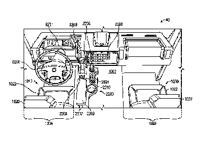
actuators 410 do not
contact the ground. Conversely, in the deployed position, the leveling
actuators 410 may engage
-22-
8247439
Date recue/Date received 2023-03-06
the ground to lift the lift base 402. The length of each of the leveling
actuators 410 in their
respective deployed positions may be varied in order to adjust the pitch
(e.g., rotational position
about a lateral axis) and the roll (e.g., rotational position about a
longitudinal axis) of the lift base
402 and/or the chassis 20. Accordingly, the lengths of the leveling actuators
410 in their respective
deployed positions may be adjusted to level the lift base 402 with respect to
the direction of gravity
(e.g., on uneven, sloped, pitted, etc. terrain). The leveling actuators 410
may lift the wheel and
tire assemblies 54 off of the ground to prevent movement of the scissor lift
400 during operation.
In other embodiments, the leveling actuators 410 are omitted.
101011 The lift assembly 404 may include a series of subassemblies, shown
as scissor layers
420, each including a pair of inner members and a pair of outer members
pivotally coupled to one
another. The scissor layers 420 may be stacked atop one another in order to
form the lift assembly
404, such that movement of one scissor layer 420 causes a similar movement in
all of the other
scissor layers 420. The scissor layers 420 extend between and couple the lift
base 402 and an
operator platform (e.g., the platform assembly 430). In some embodiments,
scissor layers 420 may
be added to, or removed from, the lift assembly 404 in order to increase, or
decrease, the fully
extended height of the lift assembly 404.
101021 Referring still to FIG. 13, the lift assembly 404 may also include
one or more lift
actuators 424 (e.g., hydraulic cylinders, pneumatic cylinders, electric linear
actuators such as
motor-driven leadscrews, etc.) configured to extend and retract the lift
assembly 404. The lift
actuators 424 may be pivotally coupled to inner members of various scissor
layers 420, or
otherwise arranged within the lift assembly 404.
101031 A distal or upper end of the lift assembly 404 is coupled to an
operator platform, shown
as platform assembly 430. The platform assembly 430 may perform similar
functions to the
platform assembly 370, such as supporting one or more operators, accessories,
and/or tools. The
platform assembly 430 may include a control panel to control operation of the
scissor lift 400. The
lift actuators 424 may be configured to actuate the lift assembly 404 to
selectively reposition the
platform assembly 430 between a lowered position (e.g., where the platform
assembly 430 is
-23-
8247439
Date recue/Date received 2023-03-06
proximate to the lift base 402) and a raised position (e.g., where the
platform assembly 430 is at
an elevated height relative to the lift base 402). Specifically, in some
embodiments, extension of
the lift actuators 424 moves the platform assembly 430 upward (e.g., extending
the lift assembly
404), and retraction of the lift actuators 424 moves the platform assembly 430
downward (e.g.,
retracting the lift assembly 404). In other embodiments, extension of the lift
actuators 424 retracts
the lift assembly 404, and retraction of the lift actuators 424 extends the
lift assembly 404.
Ergonomic Vehicle Cab
101041 According to an exemplary embodiment, as shown in FIG. 9A, the chassis
20 of a
vehicle 10 includes a first frame rail, shown as frame rail 902, and a second
frame rail, shown as
frame rail 904. The first frame rail 902 and the second frame rail 904 may
extend continuously
along the entire length of the vehicle 10. In other embodiments, the first and
second frame rails
902, 904 extend only a portion of the length of the vehicle 10. In one
embodiment, the first frame
rail 902 is parallel to the second frame rail 904. In another embodiment, at
least one portion of the
first frame rail 902 is parallel to at least one portion of the second frame
rail 904. In another
embodiment, the first frame rail 902 and the second frame rail 904 have a
uniform cross-section
along the entire length of the frame rails 902, 904. In such an embodiment,
each frame rail 902,
904 defines a constant size and shape along the entire frame rail 902, 904. In
another embodiment,
the first frame rail 902 and the second frame rail 904 do not have a uniform
cross-section along
the entire length of the frame rails 902, 904. In some embodiments, the first
frame rail 902 minors
the second frame rail 904 (e.g., the first frame rail 902 and the second frame
rail 904 define
reflective symmetry about a center axis extending longitudinally along a
centerline of the chassis
20). In other embodiments, the first frame rail 902 is different from the
second frame rail 904.
101051
According to an exemplary embodiment, as shown in FIG. 9A, the chassis 20
includes
three sections. The chassis 20 may include a first section, shown as front
portion 906, a second
section, shown as transition portion 908, and a third section, shown as rear
portion 910. The front
portion 906 may correspond to a front portion of the first frame rail 902 and
a front portion of the
second frame rail 904. The transition portion 908 may correspond to a
transition portion of the first
-24-
8247439
Date recue/Date received 2023-03-06
frame rail 902 and a transition portion of the second frame rail 904. The rear
portion 910 may
correspond to a rear portion of the first frame rail 902 and a rear portion of
the second frame rail
904. The front portion 906 may define a width, shown as first width 912. The
first width 912 may
be defined by a distance laterally between an exterior of the front portion of
the first frame rail 902
and an exterior of the front portion of the second frame rail 904. The rear
portion 910 may define
a width, shown as second width 914. The second width 914 may be defined by a
distance laterally
between an exterior of the rear portion of the first frame rail 902 and an
exterior of the rear portion
of the second frame rail 904. In one embodiment, the first width 912 is
smaller than the second
width 914. In such an embodiment, the chassis 20 comprises an inward-offset
rail configuration.
In another embodiment, the first width 912 is larger than the second width
914. In such an
embodiment, the chassis 20 comprises an outward-offset rail configuration. In
another
embodiment, the first width 912 and the second width 914 are the same. In
other embodiments,
the chassis 20 has more or less sections.
10106] In one embodiment, the front portion 906 is disposed at the same
elevation (e.g., a height
off a ground on which the vehicle 10 travels) as the rear portion 910. In
another exemplary
embodiment, the front portion 906 is disposed at a different elevation than
the rear portion 910. In
one embodiment, the front portion 906 is disposed lower than the rear portion
910. In another
embodiment, the front portion 906 is disposed higher than the rear portion
910.
101071 In one embodiment, the front portions of the frame rails 902, 904
are the same size as
the rear portions of the frame rails 902, 904. The front portions of the frame
rails 902, 904 may
have the same length as the rear portions of the frame rails 902, 904. The
front portions of the
frame rails 902, 904 may have the same width as the rear portions of the frame
rails 902, 904. In
another embodiment, the front portions of the frame rails 902, 904 are a
different size than the rear
portions of the frame rails 902, 904. The front portions of the frame rails
902, 904 may have a
different length than the rear portions of the frame rails 902, 904. In one
embodiment, the front
portions of the frame rails 902, 904 is longer than the rear portions of the
frame rails 902, 904. In
another embodiment, the front portions of the frame rails 902, 904 is shorter
than the rear portions
of the frame rails 902, 904.
-25-
8247439
Date recue/Date received 2023-03-06
101081 According to an exemplary embodiment, the transition portion 908
couples the front
portion 906 with the rear portion 910. As shown in FIG. 9A, the transition
portion 908 extends
from a rear side of the front portion 906 to a front side of the rear portion
910. According to an
exemplary embodiment, the transition portion 908 is oriented at an angle
compared to the front
portion 906 and the rear portion 910 (e.g., not parallel to the front portion
906 or the rear portion
910). The transition portion 908 may be any size, shape, or orientation
configured to couple the
front portion 906 with the rear portion 910. In an exemplary embodiment, the
transition portion
908 is oriented at a gradual angle to couple the front portion 906 with the
rear portion 910. A
gradual angle may be any angle between zero and ninety degrees. A length of
the transition portion
908, shown as length 916, may be based, in part, on the angle of orientation.
In another
embodiment, the transition portion 908 is oriented at a sharper angle.
According to an exemplary
embodiment, the transition portion 908 is oriented at a ninety-degree angle.
The transition portion
908 oriented at a sharper angle may have a shorter length 916 than a
transition portion 908 oriented
at a more gradual angle. The size, shape, or orientation of the transition
portion 908 of the first
frame rail 902 may be the same as the size, shape, or orientation of the
transition portion 908 of
the second frame rail 904. Being the same may mean the transition portion 908
of the first frame
rail 902 is minoring the transition portion 908 of the second frame rail 904.
In another
embodiment, the size, shape, or orientation of the transition portion 908 of
the first frame rail 902
is different from the size, shape, or orientation of the second frame rail
904.
101091 According to an exemplary embodiment, the transition portion 908
supports a front axle
50 of the vehicle 10 and the rear portion 910 supports a rear axle 52. In
another embodiment, the
front portion 906 supports the front axle 50 and the rear portion supports the
rear axle 52. In another
embodiment, the rear portion 910 supports the front axle 50 and the rear axle
52. Any portion of
the chassis 20 may support any combination of front and rear axles 50, 52.
101101 In another embodiment, the chassis 20 supports an auxiliary axle,
shown as auxiliary
axle 911. The auxiliary axle 911 may be a pusher axle disposed in front of a
front-most drive axle
(e.g., a front-most one of the rear axles 52). In other embodiments, the
auxiliary axle 911 is a tag
axle disposed behind a rear-most drive axle (e.g., a rear-most one of the rear
axles 52). The
-26-
8247439
Date recue/Date received 2023-03-06
auxiliary axle 911 may be coupled with the chassis 20. The auxiliary axle 911
may be coupled
with any portion of the chassis 20. In other embodiments, the auxiliary axle
911 is coupled to an
external frame of the vehicle 10. In one embodiment, the external frame is
coupled with the chassis
20 such that the auxiliary axle 911 is disposed at a location offset from the
chassis 20 (e.g., behind
a back end of the chassis 20). In some embodiments, the auxiliary axle 911 may
be configured to
move between a first position (e.g., a passive position) and a second position
(e.g., an active
position). When in the first position, the auxiliary axle 911 may be disposed
at an elevation such
that a wheel and tire assembly 54 coupled with the auxiliary axle 911 does not
contact a support
surface (e.g., the ground). In the first position, the auxiliary axle 911 may
provide no support for
the weight of the vehicle 10. When in the second position, the auxiliary axle
911 may be disposed
at an elevation such that the wheel and tire assembly 54 coupled with the
auxiliary axle 911 does
contact a support surface (e.g., the ground). In the second position, the
auxiliary axle 911 does
provide support for the weight of the vehicle 10.
[OM] In some embodiments, the chassis 20 does not have a transition portion
908. The chassis
20 may include only one portion that extends the whole length of the vehicle
10. In other
embodiments, the chassis 20 may include a front portion 906 that extends from
a front side of the
rear portion 910. In another embodiment, the front portion 906 and the rear
portion 910 can
overlap.
101121 According to another exemplary embodiment, as shown in FIG. 9B, the
chassis 20 can
include a first frame rail 902, a second frame rail 904, and an extension
structure, shown as frame
extension 918. The frame extension 918 may comprise a single section or the
frame extension 918
may comprise a plurality of sections. In one embodiment, the first frame rail
902 and the second
frame rail 904 comprise a rear portion 910 of the chassis 20 and the frame
extension 918 comprises
a front portion 906 of the chassis 20. In another embodiment, the frame
extension 918 comprises
the front portion 906 and a transition portion 908 of the chassis 20. In some
embodiments, the
frame extension 918 is configured to bolt to the frame rails 902, 904 of the
chassis 20. As shown
in FIG. 9B, the frame extension 918 is configured to fit between the frame
rails 902, 904 such that
the frame extension 918 can be bolted to an inner surface of each frame rail
902, 904. The frame
-27-
8247439
Date recue/Date received 2023-03-06
extension 918 may also be bolted to other portions of the frame rails 902, 904
(e.g., flanges, top,
bottom, etc.). In another embodiment, the frame rails 902, 904 fit inside the
frame extension 918.
In such an embodiment, the frame extension 918 is configured to be bolted to
an outer surface of
each frame rail 902, 904.
101131 According to an exemplary embodiment, as shown in FIG. 9B, the frame
extension 918
defines the transition portion 908 and the front portion 906. The transition
portion 908 may be at
least partially disposed between the first frame rail 902 and the second frame
rail 904. The frame
extension 918 may be coupled with the frame rails 902, 904. In some
embodiments, the frame
extension 918 is bolted to the inside of the frame rails 902, 904. In one
embodiment, the transition
portion 908 extends forward from the frame rails 902, 904. In another
embodiment, the frame
extension 918 is a single portion (e.g., does not include both a front portion
906 and a transition
portion 908) such that the frame extension 918 is capable of supporting the
cab 40. As shown in
FIG. 9B, the frame extension 918 starts with a height similar to the height of
the frame rails 902,
904. In one embodiment, that height of the frame extension 918 can extend
until the front portion
906. In another embodiment, the frame extension 918 can taper downwardly as it
extends toward
the front portion 906 such that a front of the frame extension 918 is at a
lower height than a back
of the frame extension 918. In other embodiments, the front of the frame
extension 918 defines a
height that is greater than the back of the frame extension 918. In another
embodiment, at least
part of the frame extension 918 has a width similar to the width 914 of the
rear portion 910 of the
chassis 20 (e.g., the frame extension 918 can couple with both frame rails
902, 904). In another
embodiment, the frame extension 918 defines more than one width. In one
embodiment, the
transition portion 908 of the frame extension 918 has a first width and the
front portion 906 has a
second width. In another embodiment, the transition portion 908 includes a
first width and a second
width, and the front portion 906 includes a third width. In such an example,
the transition portion
908 starts with a width similar to the width 914 of the rear portion 910 of
the chassis 20 and
becomes a different width as the frame extension 918 extends away from the
rear portion 910 of
the chassis 20. The width of the frame extension 918 may increase or decrease
as it extends away
from the rear portion 910. In one embodiment, the front portion 906 of the
frame extension 918
-28-
8247439
Date recue/Date received 2023-03-06
extends in a direction perpendicular to the frame rails 902, 904. In some
embodiments, the front
portion 906 has a width that is at least twice as wide as the part of the
transition portion 908 that
couples with the front portion 906.
101141 According to an exemplary embodiment, as shown in FIGS. 10-12, a cab
40 of a vehicle
includes a tunnel, shown as tunnel 1002. The tunnel 1002 protrudes into a cab
interior 42 and
extends longitudinally along the cab 40 (e.g., in a direction substantially
parallel to the frame rails
902, 904). The tunnel 1002 may be a recess defined by the body of the cab 40
that is configured
to receive at least part of the chassis 20. In some embodiments, the cab 40 is
supported by at least
the front portion 906 of the chassis 20. In some embodiments, the front
portion 906 of the chassis
is disposed within the tunnel 1002 and supports the chassis 20 via the tunnel
1002. In other
embodiments, the front portion 906 of the chassis 20 is wider than the tunnel
1002 such that front
portion 906 does not fit in the tunnel 1002. In such an embodiment, the bottom
of the cab 40 rests
on top of the front portion 906 of the chassis 20. In such an embodiment, a
transition portion 908
of the chassis 20 may be configured to be disposed, at least partially, within
the tunnel 1002 and
couple with a front portion 906 that is disposed below the tunnel 1002. The
tunnel 1002 may extend
a full length of the cab 40 or may extend only part of the length of the cab
40. The tunnel 1002
may divide the cab interior 42 into sides, shown as first side 1004 and second
side 1006. Both the
first side 1004 and the second side 1006 may be configured to provide an
operator of the vehicle
10 with room, comfort, and accessibility to operate the vehicle 10. The sides
1004, 1006 may be
configured the same or they may be configured differently.
101151 According to an exemplary embodiment, a width 1008 of the tunnel
1002 is based, at
least in part, on the width 912 of the front portion 906 of the chassis 20.
For example, the lateral
width 1008 of the tunnel 1002 is greater than the width 912 defined laterally
between exteriors of
the first frame rail 902 and the second frame 904 rail at the front portion
906 of the chassis 20.
This arrangement enables the front portion 906 of the chassis 20 to be at
least partially received
within the tunnel 1002, which efficiently supports the cab 40 on the chassis
20 and enables the cab
40 to define a smaller lateral width when compared due to conventional cab
designs. The tunnel
1002 may have a width 1008 large enough to fit the front portion of the first
frame rail 902 and the
-29-
8247439
Date recue/Date received 2023-03-06
front portion of the second frame rail 904 within the tunnel 1002. The smaller
the width 912, the
smaller the width 1008 of the tunnel 1002 may be. In another embodiment, the
width 1008 is
smaller than the width 914 of the rear portion 910 of the chassis 20. In such
an embodiment, the
width 912 of the front portion 906 is smaller than the width 914 of the rear
portion 910. The width
1008 of the tunnel 1002 may be configured to accommodate the front portion 906
and not the rear
portion 910.
101161 In another embodiment, a width 1008 of the tunnel is based, at least
in part, on the width
of a transition portion 908 of a frame extension 918. The frame extension 918
may extend within
the tunnel 1002 such that the front portion 906 is disposed either within the
tunnel 1002 or below
the cab 40 so as to support at least a front portion of the cab 40.
101171 As shown in FIGS. 10-12, each side 1004, 1006 of the cab 40 includes
a seat 1010 for
an operator, according to an exemplary embodiment. In other embodiments, only
one side of the
cab 40 includes a seat 1010. The seat 1010 includes a back portion, shown as
back rest 1020, and
a bottom portion or cushion, shown as seat support 1022. In one embodiment, a
location of the
seat 1010 is based, at least in part, on the width 1008 of the tunnel 1002.
The smaller the width
1008 of the tunnel 1002, the closer to the center of the cab 40 the seat 1010
may be. In other words,
the smaller the width 1008 of the tunnel 1002, the closer a first seat 1010
may be laterally to a
second seat 1010. According to an exemplary embodiment, a distance 1012
between a centerline
of a first seat 1010 and a centerline of a second seat 1010 is less than or
equal to about 45 inches.
In one embodiment, the cab 40 includes a display 1018 fixed to a front console
(e.g., dashboard)
of the cab 40. The first seat 1010 and the second seat 1010 can be disposed
such that an operator
in both seats 1010 can access the display. The display 1018 may include input
devices (e.g.,
buttons, switches, levers, pedals, etc.) or output devices (e.g., lights,
gauges, speakers, etc.), or any
combination thereof, that aid in the operation of the vehicle 10. The display
1018 may be
configured to be accessible by an operator on either side 1004, 1006 of the
cab 40 without having
to move at all (e.g., all components are stationary), or with only moving
slightly (e.g., swivel, tilt,
etc.). In other embodiments, the cab 40 includes separate displays 1018 for
each side 1004, 1006
of the cab 40.
-30-
8247439
Date recue/Date received 2023-03-06
101181 According to an exemplary embodiment, the location of the seat 1010
provides adequate
clearance, shown as clearance 1024, for an operator. In one embodiment, the
location of the seat
provides a shoulder clearance measured from a centerline of the seat 1010 to
an inner surface of a
door 1404 of the cab 40, or a component thereof (e.g., a window, a handle, an
armrest), of greater
than or equal to about 18 inches or greater than or equal to about 18.5
inches. In another
embodiment, the location of the seat 1010 provides an elbow clearance measured
from the
centerline of the seat 1010 to an inner surface of a door 1404 of the cab 40
of greater than or equal
to about 15 inches or greater than or equal to about 15.5 inches. In one
embodiment, a window on
a door of the cab 40 is positioned rearward to provide additional shoulder or
elbow clearance.
101191 The body of the cab 40 defines a front width 1014 and a rear width
1016. In general, the
lateral widths 1014, 1016 defined by the cab 40 are smaller than convention
cab designs, which
enables the cab 40 to provide better visibility for an operator within the cab
interior 42. In some
embodiments, the widths 1014, 1016 may be measured from an exterior of a first
side of the cab
40 to an exterior of a second side of the cab 40. In some embodiments, the
front width 1014 is
smaller than the back width 1016. In some embodiments, the front width 1014 is
a maximum of
about 80 inches. For example, the front width 1014 may be less than or equal
to about 80 inches.
In some embodiments, the rear width 1016 is maximum of about 86 inches. For
example, the rear
width may be less than or equal to about 86 inches.
101201 According to an exemplary embodiment, as shown in FIG. 12, a height
1102 of the
tunnel 1002 is based, at least in part, on a height 1108 of a top of the front
portion 906 of the
chassis 20. For example, the height 1102 of the tunnel 1002 may be defined
between a bottom
surface 1104 of the cab 40 and an uppermost surface or top 1106 of the tunnel
1002. In some
embodiments, the height 1108 of the front portion 906 of the chassis 20 may be
different than the
height of the rear portion 910 of the chassis 20. According to an exemplary
embodiment, a portion
of the tunnel 1002 rests on top of the front portion 906 of the chassis 20.
The portion of the tunnel
1002 may directly contact the chassis 20. Direct contact may include the
tunnel 1002 directly
contacting the chassis 20 without any other material separating the tunnel
1002 from the chassis
20. Direct contact may also include other material or small devices that are
disposed between the
-31-
8247439
Date recue/Date received 2023-03-06
tunnel 1002 and the chassis (e.g., padding, fasteners, supportive devices,
etc.). In other
embodiments, the chassis 20 contacts the tunnel 1002 indirectly. Indirect
contact may include
having a larger obstruction or piece of equipment disposed between the chassis
20 and the tunnel
1002 (e.g., an engine disposed in the tunnel 1002, etc.).
101211 In some embodiments, a clearance distance 1110 is defined between
the bottom surface
1104 of the cab 40 and a ground 1112. The clearance distance 1110 may have a
minimum distance
specified by industry standard. According to an embodiment, the industry
standard for the
clearance distance 1110 is 13 inches above the ground 1112 and the height 1108
of the top of the
front portion 906 of the chassis 20 is about 35 inches. In such an embodiment,
the height 1102 of
the tunnel 1002 is about 22 inches.
101221 In another embodiment, the height 1102 of the tunnel 1002 is based,
at least on part, on
a height of a top of the frame extension 918. The frame extension 918 may be
disposed within the
tunnel 1002 such that the height 1102 of the tunnel 1002 accommodates the
height of the frame
extension 918. The height of the frame extension 918 may vary so the height
1102 of the tunnel
1002 may vary accordingly.
101231 According to an exemplary embodiment, the top 1106 of the tunnel
1002 is lower than
atop of the seat support 1022 (e.g., closer to the ground 1112). In some
embodiments, the top 1106
of the tunnel 1002 is lower than the entire seat support 1022. In such an
embodiment, the seat 1010
may be positioned such that part of the seat support 1022 is disposed over the
tunnel 1002.
Similarly, an arm or shoulder of an operator sitting in the seat 1010 may be
disposed above the
tunnel 1002 since there is no obstruction preventing such arrangement. In
general, arranging the
uppermost surface or top 1106 of the tunnel 1002 below the seat supports 1022
enables the cab 40
to define a reduced lateral width (e.g., the front width 1014 and the rear
width 1016), when
compared to convention cab designs, because the seats 1010 are positioned
laterally closer to one
another (e.g., the distance 1012 is reduced when compared to convention cab
designs).
101241 According to an exemplary embodiment, as shown in FIG. 13, a rear of
the cab 40 is
supported by an external support structure, shown as support arm 1201.
Supporting the rear of the
-32-
8247439
Date recue/Date received 2023-03-06
cab 40 with the support arm 1201 allows the cab 40 to extend over other
elements of the vehicle
(e.g., a wheel and tire assembly 54) The support arm 1201 may be a part of the
cab 40 or may
be coupled to the cab 40. The support arm 1201 may extend from the cab 40 at
any location such
that an end of the support arm 1201 contacts a support point, shown as pad
1202. Pad 1202 may
include cushioning devices (e.g., suspension devices) configured to reduce the
impact of any forces
felt by the vehicle 10. Pad 1202 may include receiving devices (e.g., notches,
holes, rails, etc.)
configured to keep the support arm 1201 in a desired location. In some
embodiments, the pad 1202
is coupled to the chassis 20. In some embodiments, the pad 1202 is coupled
with a side of the
chassis 20. In other embodiments, the pad 1202 is coupled with a top of the
chassis 20. The pad
1202 is configured to receive the end of the support arm 1201 and keep the cab
40 at a desired
orientation. In some embodiments, a first support arm 1201 extends from the
cab 40 and contacts
a first pad 1202 coupled with a first frame rail 902 of the chassis 20 and a
second support arm 1201
extends from the cab 40 and contacts a second pad 1202 coupled with a second
frame rail 904. In
another embodiment, a support arm 1201 extends from the cab 40 and splits into
two support arms
1201, each configured to contact a different frame rail 902, 904. In another
embodiment, a support
arm 1201 extends from the cab 40 and contacts a pad 1202 disposed between the
two frame rails
902, 904. The pad 1202 may extend between the first frame rail 902 and the
second frame rail 904
such that the support arm 1201 contacts the pad 1202 at a location between the
first frame rail 902
and the second frame rail 904. The support arm 1201 may also be configured to
contact a portion
of the frame extension instead of, or along with, the frame rails 902. 904.
101251
According to an exemplary embodiment, the cab 40 is supported by the chassis
20 via
the tunnel 1002. In one embodiment, an entire length of the tunnel 1002 rests
upon the front portion
906 of the chassis 20. In another embodiment, a portion of the tunnel 1002
rests upon a front
portion 906 of the chassis 20. The portion of the tunnel 1002 may be a front
portion. A rear portion
of the tunnel 1002 may be supported by the support arm 1201. In another
embodiment, the cab 40
is supported by the frame extension 918 of the chassis 20. The frame extension
918 may support
the cab 40 via the tunnel 1002. In one embodiment, the front portion 906 of
the frame extension
918 is disposed within the tunnel 1002 such that at least the front of the
tunnel 1002 is supported
-33-
8247439
Date recue/Date received 2023-03-06
by the frame extension 918. In another embodiment, the front portion 906 of
the frame extension
918 is wider than the tunnel 1002 and is disposed below the tunnel 1002 such
that the bottom of
the cab 40 rests on, and is supported by, the front portion 906 of the frame
extension 918.
101261 According to an exemplary embodiment, as shown in FIG. 13, the first
side 1004 of the
cab 40 is configured to accommodate an operator in a seated position. In such
an embodiment, the
seat support 1022 of the seat 1010 is substantially horizontal such that a
person sitting on the seat
1010 does not need additional support to remain on the seat 1010 (e.g., feet
do not need to be on
the floor to keep the person in the seat). In some embodiments, the second
side 1006 is configured
to accommodate an operator in a seated position. In some embodiments, the
first side 1004 is
configured to accommodate an operator in a seated position and the second side
1006 is configured
to accommodate an operator in a non-seated or standing position (see, e.g.,
FIG. 11).
101271 In some embodiment, the first side 1004 includes a multi-step entry.
The multi-step
entry may include a plurality of steps. For example, the multi-step entry may
include a first step
1203 and a second step 1204. A first step height 1206 may be defined by a
distance between the
ground 1112 and the first step 1203. A second step height 1208 may be defined
by a distance
between the first step 1203 and the second step 1204. According to an
exemplary embodiment, the
first step height 1206 is substantially equal the second step height 1208
(e.g., +1- 0.5 inches). The
approximately equal distance between both the ground 1112 and the first step
1203, and between
the first step 1203 and the second step 1204 provides an ergonomically
efficient entry for an
operator entering the first side 1004 of the cab 40. In one embodiment, the
first step height 1206
is about 15 inches and the second step height 1208 is about 15 inches. In
other embodiments, the
sides 1004, 1006 are configured for a seated position with a single-step
entry.
101281 In one embodiment, the second step 1204 extends throughout at least
a portion of the
cab 40 to define a floor 1212. A person entering the cab 40 may stand on the
floor 1212 or may
rest their feet on the floor 1212 when in a seated position. When in a seated
configuration, a pedal
1210 for controlling a subsystem of the vehicle 10 (e.g., gas pedal, brake,
clutch, etc.) is disposed
above the floor 1212 at a location where a user can use their foot to actuate
the pedal 1210.
-34-
8247439
Date recue/Date received 2023-03-06
According to an exemplary embodiment, the second step 1204 is disposed at an
height that is
below the top of the front portion 906 of the chassis 20, and is therefore
below the top 1106 of the
tunnel 1002. In one embodiment, a height 1214 of the floor 1212 is
approximately 30 inches
measured above the ground 1112. The height 1214 of the floor 1212, and all of
the heights
described herein relative to the ground 1112, may be measured in an unloaded
bare chassis
condition.
101291 According to another exemplary embodiment, as shown in FIG. 14, the
second side
1006 of the cab 40 is configured to accommodate an operator in a non-seated or
standing
configuration. In such an embodiment, the seat support 1022 of the seat 1010
on the second side
1006 is oriented at an angle such that a person can be in a more upright
position (e.g., not arranged
parallel to the ground 1112) . The standing configuration may include the
person supporting
themselves with their feet on the floor 1212 of the cab 40. In some
embodiments, the first side
1004 is configured to accommodate an operator in a non-seated position. In
other embodiments,
neither side 1004, 1006 is configured to accommodate an operator in a non-
seated position. In
other embodiments, both sides 1004, 1006 are configured to accommodate an
operator in a non-
seated position.
101301 According to an exemplary embodiment, the second side 1006
configured for a non-
seated position includes a single-step entry. In one embodiment, the single-
step entry includes the
first step 1203 and not the second step 1204. The height 1206 of the first
step 1203 may be defined
by the distance between the ground 1112 and the first step 1203. In one
embodiment, the first step
1203 extends throughout at least a portion of the cab 40 to define the floor
1212. In such an
embodiment, the height 1206 is the same as the floor height 1214. When in a
non-seated
configuration, a pedal 1210 for controlling a subsystem of the vehicle 10
(e.g., gas pedal, brake,
clutch, etc.) is disposed above the floor 1212 at a location where a user can
use their foot to actuate
the pedal 1210. According to an exemplary embodiment, the first step 1203 is
disposed at an height
below the top of the front portion 906 of the chassis 20, and therefore is
below the top 1106 of the
tunnel 1002. In one embodiment, the floor height 1214 is approximately 15
inches measured from
the ground 1112. In other embodiments, the second side 1006 includes a multi-
step entry.
-35-
8247439
Date recue/Date received 2023-03-06
101311 According to an exemplary embodiment, the bottom of the cab 40
includes a plurality
of sections. In one embodiment, the bottom surface 1104 of the cab 40 includes
two sections,
shown as flat portion 1302 and angled portion 1304. The flat portion 1302
includes the area used
as the floor 1212 or the first step 1203. The flat portion 1302 is
substantially planar such that it
provides a flat surface for an operator to stand on to enter the cab 40. In
some embodiments, the
angled portion 1304 is in front of the flat portion 1302 (e.g., closer to a
grill, a front bumper, or a
headlight of the cab 40). In some embodiments, the angled portion 1304 is
oriented at an acute
angle with respect to the flat portion 1302. In some embodiments, the angled
portion 1304 has an
angle of approach, shown as angle 1306. The angle 1306 may be approximately 15
degrees.
101321 In some embodiments, the cab 40 includes an overhang, shown as front
overhang 1308.
The front overhang 1308 may be measured from a front axle 50 to a bumper,
shown as front
bumper 1310. In one embodiment, the front overhang 1308 is less than or equal
to about 74 inches.
101331 In some embodiments, the seat configuration of the cab 40 can switch
between a seated
configuration (FIG. 13) and a non-seated configuration (FIG. 14). A plurality
of systems or
components may move in order to switch between a seated and a non-seated
configuration. In
some embodiments, the seat 1010, the second step 1204, and the pedal 1210 are
reconfigured or
moved to accommodate a different configuration. For example, the seat support
1022 may pivot
between a substantially horizontal orientation (e.g., approximately parallel
to the ground 1112)
and a sloped orientation (e.g., not parallel to the ground 1112 where a front
of the seat support
1022 is arranged closer to the floor 1212). In one embodiment, the seat 1010
can include a
mechanism (e.g., button, lever, switch, etc.), or a combination of mechanisms,
that allow a user to
manually change the orientation of the seat 1010. Changing the orientation of
the seat may include
moving portions of the seat 1010 (e.g., tilting the seat support 1022 to be
oriented at an angle) or
removing or replacing elements of the seat 1010 (e.g., taking off or replacing
seat cushions). In
another embodiment, the cab 40 can include an automatic mechanism that
automatically changes
the orientation of the seat 1010 based on an input from a user. In one
embodiment, the automatic
mechanism includes storing user preferences in a computer system such that the
seat can
automatically reorient itself to a predefined position based on an input from
the user (e.g., the user
-36-
8247439
Date recue/Date received 2023-03-06
pushes a button and the seat 1010 moves to a preferred sloping angle
previously defined by the
user). When switching between a seated configuration and a non-seated
configuration, all
components of the seat 1010 may be adjustable (e.g., the back rest 1020, the
seat support 1022, an
armrest, a head rest, etc.). Components of the cab 40 that are not a part of
the seat 1010 may also
be adjustable (e.g., the steering wheel, pedals, controls, etc.).
101341 According to an exemplary embodiment, to switch between a seated
configuration and
a non-seated configuration, the second step 1204 may move between an active
position and a
collapsed position. In the active position, the second step 1204 provides a
floor 1212 for the cab
40. The floor 1212 is configured to support the weight of the user at an
height above the first step
1203, wherein the height is more than just a thickness of the material of the
second step 1204. In
such an embodiment, the pedal 1210 for controlling the vehicle 10 is disposed
above the second
step 1204. In the collapsed position, the second step 1204 is removed from the
cab 40 such that
the first step 1203 provides the floor 1212 for the cab 40. In one embodiment,
removing the second
step 1204 from the cab 40 includes taking the physical step out of the vehicle
10. In another
embodiment, removing the second step 1204 from the cab 40 includes swinging
the second step
1204 from a horizontal position to a vertical position such that an operator
can no longer step on
the second step 1204. In another embodiment, removing the second step 1204
includes collapsing
the second step 1204 such that it sits flat on top of the first step 1203.
101351 According to an exemplary embodiment, to switch between a seated
configuration and
a non-seated configuration, the pedal 1210 may move between a lower position
and a higher
position. The pedal 1210 may be in the higher position when in the seated
configuration. The pedal
1210 may be in the higher position when the second step 1204 is in the active
position. The pedal
1210 may be in the lower position when in the non-seated position. The pedal
1210 may be in the
lower position when the second step 1204 is in the collapsed position. In
another exemplary
embodiment, a cab 40 may include a plurality of pedals 1210. For example, a
first pedal 1210 may
be configured to be used when in the seated configuration and a second pedal
1210 may be
configured to be used when in the non-seated configuration.
-37-
8247439
Date recue/Date received 2023-03-06
101361 In general, either side 1004, 1006 of the cab 40 may define the
seated
position/configuration or the non-seated position/configuration. Regardless of
the seat
configuration, the seat 1010 can be adjusted and moved to increase comfort of
an operator. In some
embodiments, the seat 1010 can slide longitudinally (e.g., forward and
backward) to provide more
or less distance between the seat 1010 and the front of the cab 40. In one
embodiment, the seat
1010 can slide between about 8 inches and about 9 inches, or about 8.7 inches.
In other
embodiments, the seat 1010 includes a vertical suspension (e.g., can travel up
and down when on
uneven roads, etc.). In some embodiments, the seat 1010 has a vertical
suspension travel of about
6 inches. In other embodiments, the seat 1010 can recline (e.g., an angle of
the back rest 1020 can
change). In some embodiments, the seat 1010 can recline about 13 degrees.
101371 According to an exemplary embodiment, as shown in FIG. 15, the cab
40 includes at
least one side 1402. The side 1402 may include at least one door, shown as
door 1404. In one
embodiment, the door 1404, or a portion thereof, may be formed via a stamping
process. In other
embodiments, the door 1404 may be formed by other processes (e.g., molded,
pressed, etc.). The
door 1404 facilitates selective access to the cab interior 42 from outside of
the vehicle 10. In some
embodiments, the door 1404 comprises the entire side of the cab 40. In other
embodiments, the
side 1402 comprises a plurality of sections. According to an exemplary
embodiment, the side 1402
includes a first portion (the door 1404) and a second portion, shown as wall
1406. In an exemplary
embodiment, the door 1404 comprises a majority of the surface area defined by
the side 1402. In
other embodiments, the door 1404 comprises no more than half of the surface
area of the side
1402.
101381 The door 1404 may be configured to move between an open position and
a closed
position. In some embodiments, the door 1404 moves by rotating about a
vertical axis, shown as
axis 1408. The axis 1408 may be coupled with a front edge of the door 1404 or
a back edge of the
door 1404. In some embodiments, the door 1404 swings inward to open the cab
40. In other
embodiments, the door 1404 swings outward to open the cab 40. When rotating
about an axis, the
door 1404 may use piano hinges that are coupled to an edge of the door 1404.
The piano hinges
may be forward or backward hinges. In other embodiments, the door 1404 uses
other hinges. In
-38-
8247439
Date recue/Date received 2023-03-06
other embodiments, the door 1404 moves by rotating about a different axis
(e.g., horizontal, 45
degree, etc.). In other embodiments, the door 1404 moves by being removed from
the cab 40 and
replaced back onto the cab 40. In other embodiments, the door 1404 moves by
sliding along a rail
or track.
101391 In some embodiments, the wall 1406 is stationary. The wall 1406 may
provide a seal
with the door 1404 when in the closed position. In other embodiments, the wall
1406 is not
stationary. The wall 1406 may be configured to move between an open position
and a closed
position. In some embodiments, the wall 1406 moves similarly to the door 1404
(e.g., if the door
1404 rotates about an axis, the wall 1406 rotates about an axis). In other
embodiments, the wall
1406 moves different than the door 1404 (e.g., if the door 1404 rotates, the
wall 1406 slides). In
some embodiments, movement of the wall 1406 is independent from the movement
of the door
1404. In other embodiments, movement of the wall 1406 is dependent on movement
of the door
1404 (e.g., the door 1404 must open before the wall 1406 can open). In other
embodiments,
movement of the door 1404 is dependent on movement of the wall 1406.
101401 In some embodiments, the door 1404 has a width, shown as door width
1410. The door
1404 may have a plurality of widths. In one embodiment, the door width 1410
refers to the widest
part of the door 1404. In some embodiments, the door width 1410 may be less
than or equal to 36
inches wide. In some embodiments, the door 1404 is one continuous portion. In
other
embodiments, the door 1404 has a plurality of portions. According to an
exemplary embodiment,
the door 1404 has a first portion, shown as top portion 1412, and a second
portion, shown as bottom
portion 1414. In some embodiments, the top portion 1412 is taller than the
bottom portion 1414.
In other embodiments, the top portion 1412 is shorter than the bottom portion
1414. In other
embodiments, the top portion 1412 has the same height as the bottom portion
1414. In other
embodiments, the plurality of portions are arranged differently (e.g., side by
side).
101411 According to an exemplary embodiment, the top portion 1412 includes
at least one
window 1416. The at least one window 1416 may be thinner than other components
of the door
1404 (e.g., door frame, armrest, etc.) such that the window 1416 provides more
room in the cab
-39-
8247439
Date recue/Date received 2023-03-06
interior 42 than the other components of the door 1404 (e.g., more clearance
room for the operator
next to the window 1416 than next to the door frame).
101421 In some embodiments, a majority of a surface area of the top portion
1412 is comprised
of the at least one window 1416. In one embodiment, the whole top portion 1412
comprises at
least one window 1416. In such an embodiment, the top portion 1412 may include
a perimeter
1418. In some embodiments, the perimeter 1418 is as thin as an inch wide. In
other embodiments,
the perimeter 1418 is thicker than an inch. In other embodiments, the
perimeter 1418 is thinner
than an inch. In other embodiments, a majority of the surface area of the top
portion 1412 does not
comprise a window 1416 (e.g., solid wall). In another embodiment, the top
portion 1412 includes
a plurality of windows 1416. At least one of the plurality of windows 1416 may
be configured to
open and close based on operator input. The input may be electronic (e.g., the
window 1416 is
electrically controlled by a switch) or manual (e.g., the window 1416 is
manually controlled by a
handle). In other embodiments, none of the plurality of windows 1416 are
configured to open and
close.
101431 In some embodiments, each of the plurality of windows 1416 may have
a perimeter
1418. Each perimeter 1418 may be a different thickness. In other embodiments,
each perimeter
1418 is the same thickness. In some embodiments, a window 1416 is positioned
rearward on the
door 1404 to provide extra clearance (e.g., elbow and shoulder clearance) for
the operator. The
window 1416 positioned rearward on the door 1404 may also provide better
visibility for an
operator.
101441 According to an exemplary embodiment, the bottom portion 1414 of the
door 1404
includes at least one window 1416. In some embodiments, a majority of a
surface area of the
bottom portion 1414 is comprised of the at least one window 1416. In one
embodiment, the whole
bottom portion 1414 is comprised of the at least one window 1416. In such an
embodiment, the
bottom portion 1414 may include a perimeter 1418. In other embodiments, a
majority of the
surface area of the bottom portion 1414 does not comprise a window 1416. In
other embodiments,
the bottom portion 1414 includes no windows 1416.
-40-
8247439
Date recue/Date received 2023-03-06
101451
In some embodiments, the wall 1406 includes at least one cab window 1417. In
some
embodiments, a majority of a surface area of the wall 1406 is comprised of the
at least one cab
window 1417. In one embodiment, the whole wall 1406 is comprised of the at
least one cab
window 1417. In such an embodiment, the wall 1406 may include a perimeter
1418. In other
embodiments, a majority of the surface area of the wall 1406 does not comprise
a cab window
1417. In other embodiments, the wall 1406 includes no cab windows 1417.
101461 In some embodiments, the door 1404 includes an opening mechanism, shown
as
opening mechanism 1420. The opening mechanism 1420 may be any mechanism
configured to
keep the door 1404 in a closed position when activated, and release the door
1404 from the closed
position when deactivated. Activation and deactivation of the opening
mechanism 1420 can apply
to either keeping the door 1404 in the closed position or releasing the door
1404 to move into an
open position. In one embodiment, the opening mechanism 1420 is a handle. In
other
embodiments, the opening mechanism can be a lever, a button, a switch, a
toggle, a latch, a knob,
a handle, etc. In some embodiments, the opening mechanism 1420 is disposed on
the top portion
1412 of the door 1404. In another embodiment, the opening mechanism 1420 is
disposed on the
bottom portion 1414 of the door 1404. In another embodiment, the opening
mechanism 1420 is
disposed on the wall 1406. The opening mechanism 1420 may be placed anywhere
on the side
1402 of the cab 40 such that it controls the movement of the door 1404 between
the open position
and the closed position.
101471 According to an exemplary embodiment, as shown in FIG. 20, the cab 40
includes a
grab bar 2001. The grab bar 2001 may be made of any suitable material
including, but not limited
to, rubber, plastic, metal, or a combination thereof. For example, the grab
bar 2001 may form a
metal core with a rubber exterior to facilitate the ability of a user to grip
the grab bar 2001.
101481 In some embodiments, the grab bar 2001 may be coupled to and arranged
within a
portion (e.g., coupled to an interior wall) of the cab interior 42 of the cab
40. For example, as
shown in FIG. 20, the grab bar 2001 may be positioned to the left, or
laterally outwardly, of the
seat support 1022 on the first side 1004. In some embodiments, the grab bar
2001 is positioned to
-41-
8247439
Date recue/Date received 2023-03-06
the right, or laterally outwardly, of the seat support 1022 on the second side
1006. In some
embodiments, the grab bar 2001 may be positioned on the right side, or
laterally inwardly, of the
seat support 1022 on the first side 1004. In some embodiments, the grab bar
2001 may be
positioned on the left side, or laterally inwardly, of seat support 1022 on
the second side 1006. It
should be appreciated that the grab bar 2001 may be positioned in duplicative
or alternative form
including, but not limited to, any of the arrangements described herein. For
example, the cab 40
may include a grab bar 2001 positioned laterally outwardly relative to both
the seat support 1022
on the first side 1004 and the seat support 1022 on the second side 1006, so
that an operator
entering either side of the cab interior 42 may have access to a grab bar
2001. In general, the grab
bar 2001 may facilitate an operator or user reaching the cab interior 42 via
the first step 1203.
Additionally, the grab bar 2001 may facilitate support for a user during
operation of the vehicle
10.
101491 In the illustrated embodiment, the grab bar 2001 defines a generally
arced or curved
shape with a first end 2002 being arranged vertically above a second end 2003.
The grab bar 2001
is coupled to a rear wall 2004 of the cab interior 42. In some embodiments,
the first end 2002 and
the second end 2003 are both removably coupled (e.g., via bolts, clips, wall
hooks, or an equivalent
removable mounting feature) to the rear wall 2004 so that the grab bar 2001
may be removed from
the rear wall 2004 and recoupled at a different height. In other words, the
position of the grab bar
2001 may be adjustable such that a user of the vehicle 10 may position the
grab bar 2001 at an
ideal location relative to the seat 1010.
101501 In the illustrated embodiment, the grab bar 2001 may be positioned
at a height within
the cab interior 42 that generally aligns with a bottom of the back rest 1020
of the seat 1010. For
example, the first end 2002 of the grab bar 2001 may be vertically aligned
with or arranged at
about the same vertical height as an uppermost portion of the seat support
1022, and the second
end 2003 of the grab bar 2001 may be arranged vertically below the bottommost
portion of the
seat support 1022. In some embodiments, the grab bar 2001 may be positioned
further toward the
top of the back rest 1020 of the seat 1010. For example, the first end 2002 of
the grab bar 2001
may be arranged vertically above an uppermost portion of the seat support
1022, and the second
-42-
8247439
Date recue/Date received 2023-03-06
end 2003 of the grab bar 2001 may be vertically aligned with or arranged at
about the same vertical
height as the uppermost portion of the seat support 1022. In some embodiments,
the grab bar 2001
may be positioned at or near the top of the back rest 1020 of the seat 1010.
For example, the first
end 2002 and the second end 2003 of the grab bar 2001 may both be arranged
vertically above an
uppermost portion of the seat support 1022.
101511 In some embodiments, the grab bar 2001 is coupled to the rear wall
2004 of the cab
interior 42 so that the seat 1010 is allowed to move relative to the grab bar
2001 during operation
of the vehicle 10. For example, a suspension 2005 is coupled between the cab
40 and the seat
1010 that is configured to allow the seat 1010 to oscillate in response to
bumps and movements of
the cab 40. The suspension 2005 may be configured to dampen motion of the seat
1010 during
the bumps and movements experienced by the cab 40 of the vehicle 10 during
operation. In some
embodiments, the suspension 2005 includes one or more linkage rods or scissor
arms 2006 coupled
between the bottom of the seat support 1022 and an interior surface of the cab
40. In the illustrated
embodiment, the interior surface of the cab 40 is a seat platform 2007 on
which the seat 1010 is
supported. As illustrated in FIGS. 20 and 22, the suspension 2005 may be
coupled between the
seat platform 2007 and the seat 1010 in either the standing configuration
(see, e.g., FIG. 20) and/or
the sitting configuration (see, e.g., FIG. 22) of the seat 1010.
101521 In the illustrated embodiment, as shown in FIG. 22, the scissor arms
2006 are coupled
by a hinge pin 2008, and the scissor arms 2006 are configured to pivot
relative to one another about
the hinge pin 2008 so that the seat 1010 is allowed to move vertically
relative to the seat platform
2007. In some embodiments, one or more damping or biasing elements are
arranged between the
scissor arms 2006 and/or between the seat 1010 and the seat platform 2007. For
example, the
suspension 2005 may include one or more coil springs coupled between the
scissor arms 2006 that
act to dampen the relative vertical movement between the seat 1010 and the
seat platform 2007.
Alternatively or additionally, the suspension 2005 may include a shock
absorber, a strut, and/or a
piston/cylinder coupled between the seat 1010 and the seat platform 2007 to
dampen the relative
movement between the seat 1010 and the seat platform 2007.
-43-
8247439
Date recue/Date received 2023-03-06
101531 In some embodiments, the grab bar 2001 is coupled to the seat 1510
itself, such that
during operation, the grab bar 2001 moves with the seat 1510, instead of
relative to the seat 1510,
during operation of the vehicle 10.
101541 According to an exemplary embodiment, as shown in FIG. 23, the cab 40
may include
a second grab bar 2101 in addition to the grab bar 2001 (e.g., a first grab
bar 2001). In some
embodiments, the cab 40 may include the second grab bar 2101 as an alternative
to the grab bar
2001. In some embodiments, the second grab bar 2101 may be coupled to and
arranged within a
portion of the interior 42 of the cab 40. For example, the second grab bar
2101 may be positioned
to the left, or laterally outwardly, of the seat support 1022 on the first
side 1004. In some
embodiments, the second grab bar 2101 is positioned to the right, or laterally
outwardly, of the
seat support 1022 on the second side 1006. In some embodiments, the second
grab bar 2101 may
be positioned on the right side, or laterally inwardly, of the seat support
1022 on the first side 1004.
In some embodiments, the second grab bar 2101 may be positioned on the left
side, or laterally
inwardly, of seat support 1022 on the second side 1006. It should be
appreciated that the second
grab bar 2101 may be positioned in duplicative or alternative form including,
but not limited to,
any of the arrangements described herein. For example, the cab 40 may include
a second grab bar
2101 positioned laterally outwardly relative to both the seat support 1022 on
the first side 1004
and the seat support 1022 on the second side 1006, so that an operator
entering either side of the
cab interior 42 may have access to a second grab bar 2101. In general, the
second grab bar 2101
may facilitate an operator or user reaching the cab interior 42 via the first
step 1203 and the second
step 1204. Additionally, the second grab bar 2101 may facilitate support for a
user during
operation of the vehicle 10.
101551 The second grab bar 2101 is coupled to a front wall 2102 of the cab
interior 42. In some
embodiments, the second grab bar 2101 is removably coupled (e.g., via bolts,
clips, wall hooks, or
an equivalent removable mounting feature) to the front wall 2102 so that the
second grab bar 2101
may be removed from the front wall 2102 and recoupled at a different height.
In other words, the
position of the second grab bar 2101 may be adjustable such that a user of the
vehicle 10 may
position the second grab bar 2101 at an ideal location relative to the seat
1010.
-44-
8247439
Date recue/Date received 2023-03-06
101561 In the illustrated embodiment, the second grab bar 2101 is
positioned at a height within
the cab interior 42 that is generally above the height of the grab bar 2001
(i.e., above the first end
2002). In this way, for example, a user may initially grasp the grab bar 2001
when entering the
cab interior 42 and subsequently grab the second grab bar 2101 as the user
steps upwardly into the
cab interior 42. Also, the second grab bar 2101 being arranged on a laterally
opposing wall relative
to the grab bar 2001 (i.e., the front wall 2102 is laterally opposite to the
rear wall 2004) provides
lateral stability to a user entering the cab interior 42. In some embodiments,
the second grab bar
2101 is positioned at a height that at least partially overlaps with the grab
bar 2001 (i.e., at least a
portion of the grab bar 2001 and the second grab bar 2101 are arranged at the
same height).
101571 In some embodiments, the second grab bar 2101 is rigidly coupled to
the front wall 2102
such that it does not move with the seat 1010 with respect to the motion of
the suspension 2005
described herein. In some embodiments, the second grab bar 2101 is slidably
coupled to the front
wall 2102, such that if a user is holding the second grab bar 2101 during
operation of the vehicle
10, the second grab bar 2101 is configured to move with the relative motion of
the seat 1010
relative to the cab 40.
101581 According to an exemplary embodiment, as shown in FIG. 24, the cab 40
may include
a control console 2200 arranged within the cab interior 42. In the illustrated
embodiment, the
control console 2200 is positioned on the right side (e.g., a laterally inward
side) of the seat 1010
on the first side 1004, near a steering wheel 2205. In other embodiments, the
control console 2200
may be positioned on the left side (e.g., a laterally outward side) of the
seat 1010 on the first side
1004.
101591 The control console 2200 includes a panel 2201 having buttons and
indicators that
support the functions of the vehicle 10. The control console 2200 may further
include an armrest
2209, a primary joystick 2203, a secondary joystick 2208, a gear shift 2204,
and gear shift
indicators 2210. The gear shift 2204 may be configured to change the gear of
the transmission/
components of the vehicle 10, and the gear shift indicators 2210 may be
configured to indicate the
gear of the vehicle 10 controlled by the gear shift 2204. In some embodiments,
the control console
-45-
8247439
Date recue/Date received 2023-03-06
2200 itself forms an armrest that is coupled to the seat 1010 and the armrest
2209 of the control
console 2200 is an armrest pad 2209 designed to cushion a portion of a user's
arm.
101601 In some embodiments, the primary joystick 2203 may be configured to
operate some or
all of the various implements described herein. For example, the primary
joystick 2203 may be
configured to operate the lift assembly 140. In particular, the primary
joystick 2203 may be
configured to operate the articulation actuators 148 and the lift arm
actuators 144. As another
example, the primary joystick 2203 may be configured to operate the tailgate
actuator 138 to
facilitate emptying the storage volume of vehicle 10. As another example, the
primary joystick
2203 may be configured to operate the grabber assembly 162. In particular, the
primary joystick
2203 may be configured to operate the grabber fingers 166, the track 170,
and/or the lift actuator
172. As another example, the primary joystick 2203 may be configured to
operate the drum
assembly 230. In particular, the primary joystick 2203 may be configured to
operate the drum
drive system 234 and the chute 238. As another example, the primary joystick
2203 may be
configured to operate the ladder assembly 254. In particular, the primary
joystick 2203 may be
configured to operate the turntable 262 and the monitor 264. As another
example, the primary
joystick 2203 may be configured to operate the boom assembly 354. In
particular, the primary
joystick 2203 may be configured to operate the lower lift cylinder 364, the
turntable 352, the lower
boom 360, and/or the upper lift cylinder 366. As another example, the primary
joystick 2203 may
be configured to operate the platform assembly 370. In particular, the primary
joystick 2203 may
be configured to operate the jib arm 372. As yet another example still, the
primary joystick 2203
may be configured to operate the lift assembly 404. In particular, the primary
joystick 2203 may
be configured to operate the leveling actuators 410, the scissor layers 420,
and/or the lift actuators
424. It should be appreciated that the primary joystick 2203 may be configured
to operate any of
the implements described herein, including or in addition to any of the
examples discussed herein.
101611 In some embodiments, the primary joystick 2203 and the secondary
joystick 2208 may
be configured to each operate some or all of the various implements described
herein. For
example, the primary joystick 2203 may be configured to operate implements
more frequently
used in the regular operation of the vehicle 10, while the secondary joystick
2208 may be
-46-
8247439
Date recue/Date received 2023-03-06
configured to operate the implements less frequently used in the regular
operation of the vehicle
10. In other embodiments, the primary joystick 2203 may be configured to
operate implements
associated with one or more subsystems of the vehicle 10, while the secondary
joystick 2208 may
be configured to operate a different one or more subsystems of the vehicle 10
than those operated
by the primary joystick 2203.
101621 In some embodiments, the operation of the primary joystick 2203 may
be supported by
any of the other components of the control console 2200, a user interface
2202, or a display screen
2211. For example, the user interface 2202 may show live camera footage of the
implement being
operated by the primary joystick 2203 or a digital representation of the
implement being operated
by the primary joystick 2203. In some embodiments, the user interface 2202
functions as the
display 1018 described herein. Further, the user interface 2202 may display
the status of various
implements and functions of the vehicle 10. The user interface 2202 may
include a touchscreen
configured to allow a user to select a particular implement to operate with
the primary joystick
2203. The operation of the various implements using the primary joystick 2203
may be supported
or supplemented by the indicators or buttons coupled to the control console
2200. For example,
the indicators (e.g., on the user interface 2202 or the panel 2201) may light
up to indicate a status
of one of the implements being operated by the primary joystick 2203. In some
embodiments, the
display screen 2211 may be configured to perform some or all of the functions
described herein
regarding the user interface 2202. In some embodiments, the display screen
2211 may be
configured to display video footage of the exterior of the vehicle 10.
101631 In some embodiments, the control console 2200 may be pivotable
around a pivot 2207.
For example, the control console 2200 may be configured to rotate upward
toward the top of the
seat 1510 or back down toward the bottom of the seat 1510. As another example,
the control
console 2200 may be configured to rotate right and left relative to the pivot
2207 (e.g., in a
direction toward or away from the steering wheel 2205).
101641 In some embodiments, the control console 2200 is coupled to the cab
40 such that the
control console 2200 moves with the seat 1010. As described above, the seat
1010 may move
-47-
8247439
Date recue/Date received 2023-03-06
relative to the cab 40 due to the suspension 2005. The control console 2200
may be configured to
move with the seat 1010 such that bumps and changes of position of the vehicle
10 do not obstruct
the operation of the components of the control console 2200, such as the
primary joystick 2203,
during operation. In some embodiments, as shown in FIG. 25, the control
console 2200 is coupled
to the cab 40 or the seat platform 2007 by the suspension 2005 (e.g.,
separately from the seat 1010)
such that it does not move relative to the seat 1010 during operation of the
vehicle 10. In this
configuration, the suspension 2005 supports the seat 1010 and the control
console 2200 separately,
and may account for different masses of the seat 1010 (and an operator
therein) and the control
console 2200 by including different springs, shock absorbers, struts, and/or a
piston/cylinders that
support the control console 2200, compared to those that support the seat
1010. This ensures that
the relative motion between the seat 1010 and the cab 40 is the same as the
relative motion between
the control console 2200 and the cab 40 (i.e., the control console 2200 is
inhibited from moving
relative to the seat 1010). In other words, the position of the control
console 2200 relative to the
seat 1010 is maintained during operation of the vehicle 10.
101651
In some embodiments, as shown in FIG. 26, the suspension 2005 is coupled
between
the seat 1010 and the seat platform 2007 of the cab 40, and the control
console 2200 is coupled to
the seat 1010 so that the control console 2200 moves with the seat 1010. In
this way, for example,
the suspension 2005 supports both the seat 1010 and the control console 2200
together and a
position of the control console 2200 relative to the seat 1010 is maintained
during operation of the
vehicle 10 (e.g., the control console 2200 moves with the seat 1010 during
relative movement
between the cab 40 and the seat 1010 facilitated by the suspension 2005).
101661 According to an exemplary embodiment, as shown in FIG. 27, the cab 40
may include
multiple control consoles 2200. For example, a control console 2200 may be
further positioned
on or near the second side 1006 of the cab 40 in addition to, or as an
alternative to, the first side
1004. In this way, for example, an operator of the vehicle 10 may operate the
various
implements/functions of the vehicle 10 as described herein while riding in the
seat 1010 on the
second side 1006. In some embodiments, the cab 40 includes a first control
console 2200 coupled
to the seat 1010 arranged on the first side 1004 and a second control console
2200 coupled to the
-48-
8247439
Date recue/Date received 2023-03-06
seat 1010 arranged on the second side 1006. In the illustrated embodiment, the
first control console
2200 and the second control console 2200 are mounted inwardly on their
respective seats 1010
(e.g., laterally inwardly).
101671 As shown in FIG. 28, the one or more components of the cab 40 may be
communicably
coupled to a control system 2400 having a controller 2402. The controller 2402
is configured to
receive different sensor or input data from a variety of devices/components,
and provide control
data to various systems, sub-systems, etc., of the vehicle 10. In some
embodiments, the controller
2402 is a native controller on the vehicle 10 that communicates over a vehicle
CAN bus. In some
embodiments, the controller 2402 is a dedicated controller that is included on
the vehicle 10 to
control operations within the cab 40. The controller 2402 includes a
processing circuit 2424 having
a processor 2426 and memory 2428. The processing circuit 2424 can be
communicably connected
to a communications interface such that the processing circuit 2424 and the
various components
thereof can send and receive data via the communications interface. The
processor 2426 can be
implemented as a general purpose processor, an application specific integrated
circuit ("ASIC"),
one or more field programmable gate arrays ("FPGAs"), a group of processing
components, or
other suitable electronic processing components.
101681
The memory 2428 (e.g., memory, memory unit, storage device, etc.) can include
one or
more devices (e.g., RAM, ROM, Flash memory, hard disk storage, etc.) for
storing data and/or
computer code for completing or facilitating the various processes, layers and
modules described
in the present application. The memory 2428 can be or include volatile memory
or non-volatile
memory. The memory 2428 can include database components, object code
components, script
components, or any other type of information structure for supporting the
various activities and
information structures described in the present application. According to some
embodiments, the
memory 2428 is communicably connected to the processor 2426 via the processing
circuit 2424
and includes computer code for executing (e.g., by the processing circuit 2424
and/or the processor
2426) one or more processes described herein.
-49-
8247439
Date recue/Date received 2023-03-06
101691 In the illustrated embodiment, the vehicle 10 can include a posture
sensor 2430, a
seatbelt sensor 2432, a weight sensor 2434, one or more cameras 2446, a user
interface 2202, and
a human machine interface (HMI) 2436. In some embodiments, the HMI 2436 may
include
components such as the steering wheel 2205, the primary joystick 2203, the
secondary joystick
2208, the gear shift 2204, the pedals 1210, the panel 2201, the user interface
2202, and/or an
ignition 2345. The controller 2402 may be configured to determine various
conditions of the cab
40, particularly conditions unique to dual drive embodiments (e.g., right-hand
drive or left-hand
drive operational modes), and provide control outputs to the various
components of the control
system 2400.
101701 In some embodiments, a camera (e.g., one of the cameras 2446) is
positioned within the
cab 40 and the controller 2402 is configured to use image data from the camera
to determine
position(s) of the operator(s) within the cab 40. For example, the controller
2402 may be
configured to determine, via one or more of the cameras 2446, whether there is
an operator in the
seat 1010 on the first side 1004 and/or the seat 1010 on the second side 1006.
In other
embodiments, various sensors (e.g., the weight sensors 2434, the posture
sensors 2430, the seatbelt
sensors 2432, etc.) are positioned throughout the cab 40 to determine the
position and/or presence
of an operator within the cab 40.
101711 In some embodiments, the controller 2402 is configured to operate
the user interface
2202 to provide the real-time image data obtained from the cameras 2446 or to
provide the real-
time image data of the cameras 2446 to a secondary display (e.g., the display
screen 2211). In
some embodiments, the user interface 2202 or the secondary display is
positioned within the cab
40 such that the user interface 2202 is viewable from any driving position
within the cab 40 (e.g.,
either the seat 1010 on the first side 1004 or the second side 1006). In some
embodiments, various
settings of the user interface 2202 may be adjusted by the controller 2402.
101721 In some embodiments, the vehicle 10 (e.g., the refuse vehicle 100)
may include a pair
of mirrors 19, as shown in FIGS. 3, 5, 7, and 9, with each mirror 19
positioned on laterally opposing
sides of an exterior of the vehicle 10 (e.g., proximate the cab 40) and
viewable from the cab interior
-50-
8247439
Date recue/Date received 2023-03-06
42. Various settings regarding the mirrors 19 may be adjusted by the
controller 2402 (e.g.,
position, orientation, etc.).
101731 Referring to FIGS. 27 and 28, in some embodiments, the cab 40 of the
vehicle 10 (e.g.,
the refuse vehicle 100) includes drive components/capabilities (e.g., pedals
1210, control consoles
2200, steering wheels 2205, etc.) on both the first side 1004 and the second
side 1006 of the cab
interior 42. As used herein, the terms "drive component(s)" or "vehicle
operator interface(s)"
mean any component/interface (e.g., pedals, steering wheels, joysticks,
levers, user interfaces,
buttons, switches, etc.) that, when manipulated, is capable of causing
movement or travel of a
function (e.g., motor, actuator, pump, transmission, etc.) on a vehicle or
movement or travel of the
vehicle itself. For example, drive components within the cab 40 of the vehicle
10 (e.g., the refuse
vehicle 100) may include the pedals 1210, the steering wheels 2205, the
primary joysticks 2203,
the secondary joysticks 2208, buttons or switches on the panel 2201, the gear
shifts 2204, any
graphical buttons appearing on the user interface 2202, etc.
101741 The controller 2402 may be configured to adjust various settings
involved with the
operation of the drive components within the cab 40. For example, with drive
components/vehicle
operator interfaces being arranged on both the first side 1004 and the second
side 1006 of the cab
interior 42, the controller 2402 may be configured be selectively allow
operation of the drive
components on either the first side 1004 or the second side 1006 based on the
criteria described
herein. Determining which of the first side 1004 or the second side 1006, if
any, to allow operation
of the drive components may be based on a determination of the presence of an
operator on the
first side 1004 (e.g., in the seat 1010) and/or the second side 1006 (e.g., in
the seat 1010). In some
embodiments, the determination of the presence of operator(s) on the first
side 1004 and/or the
second side1506 may be based on data provided by the weight sensor(s) 2434,
the seatbelt sensors
2432, an activation switch 2435, and/or the posture sensors 2430. For example,
the weight sensor
2434 may be positioned within or underneath each of the seat(s) 1010. When an
operator positions
themselves on either of the seat(s) 1010, the weight sensor(s) 2434 may
transmit a measurement
of the amount of weight resting on the seat(s) 1010 (e.g., on the seat
supports 1022). The controller
2402 may receive the weight measurement(s) and determine whether an operator
is present in the
-51-
8247439
Date recue/Date received 2023-03-06
first side 1004 and/or the second side 1006. For example, the memory 2428 may
store a threshold
weight (e.g., 100 pounds) that may be referenced by the controller 2402. If
either of the weight
measurement(s) received by the controller 2402 meet or exceed the threshold
weight, the controller
2402 may make a determination that an operator is present on the first side
1004 and/or the second
side 1006 and enable the drive components on that side. The threshold weight
may be set such
that various utility items may be placed on one of the seat(s) 1010 without
necessarily triggering
a determination by the controller 2402 that an operator is present. In some
embodiments, data
received from the posture sensor 2430 (indicating whether an operator, while
detected in one of
the seats 1010, is in fact in position to drive) or the seatbelt sensor
(indicating whether an operator
has engaged the seat belt of the seat 1010 or not) may, either alone or in
combination with the
other sensors described herein, be used by the controller 2402 to make a
determination as to user
presence in the cab 40. In some embodiments, activation of an activation
switch 2435 may indicate
to the controller 2402 the presence of an operator and grant control to the
side of the cab 40 that
the activation of the activation switch 2435 originates from (e.g., the cab 40
may include an
activation switch 2435 on the first side 1004 and the second side 1006). In
some embodiments,
the activation switch 2435 may be arranged within the panel 2201, the user
interface 2202, and/or
the display screen 2211.
101751 In some embodiments, one of the camera(s) 2446 may provide image data
to the
controller 2402 of the region of the cab 40 on or around the seat(s) 1010. The
controller 2402 may
receive the image data from the camera(s) 2446 and determine whether an
operator is present on
the first side 1004 and/or the second side 1006. For example, a single camera
2446 may feature a
wide-angle field of view and be configured to collect image data from both the
first side 1004 and
the second side 1006 of the cab interior 42. With a wide-angle field of view,
the image data may
be provided by a single camera 2446 to differentiate between the first side
1004 and the second
side 1006. As another example, two or more cameras 2446 may be positioned
within the cab
interior 42 to provide separate sets of image data associated with the first
side 1004 and the second
side 1006. As another example still, a single camera 2446 (without a wide
lens) may be configured
to operate in conjunction with the weight sensor(s) 2434 and reposition toward
the first side 1004
-52-
8247439
Date recue/Date received 2023-03-06
or the second side 1006 based on the weight sensor(s) 2434 detecting a
threshold weight on the
seat(s) 1010. Based on the data from one of the cameras 2446 or other sensors
described herein,
the controller 2402 may make a determination regarding operator presence and
adjust the other
cameras 2446 (e.g., the cameras 2446 collecting image data outside the cab 40)
for an improved
view for the driving operator.
101761 In some embodiments, the controller 2402 is configured to allow
operation of the drive
components within the cab 40 based on image data from the camera(s) 2446
indicating that an
operator is present within the cab 40 on at least one of the first side 1004
or the second side 1006.
In some embodiments, based on a determination that either of the seats 1010
are unoccupied, the
controller 2402 may be configured to lock/disable control of the drive
components in the
unoccupied one of the first side 1004 or the second side 1006. For example,
the controller 2402
may determine that an operator is present in the seat 1010 on the first side
1004, while no operator
is present in the seat 1010 on the second side 1006 (and vice-versa). The
controller 2402 may be
configured to allow/enable operation of the drive components within the cab 40
on the first side
1004, while not allowing/disabling operation of the drive components within
the cab 40 on the
second side 1006 (and vice-versa). Beneficially, when a single operator is
operating the vehicle
10, unintentional engagement of the drive controls on the unoccupied side of
the cab 40 (e.g., a
stray object rolling and/or falling about the cab 40, the single operator
reaching into the unoccupied
side and making unintentional contact with controls on the unoccupied etc.) is
avoided by the
controller 2402 because the controller 2402 only enables the drive components
on the occupied
side of the cab 40. As another example, the controller 2402 may determine that
no operator is
present in either seat 1010 within the cab 40, and the controller 2402 may not
allow control of the
drive components within the cab on either the first side 1004 or the second
side 1006. Beneficially,
the controller 2402 may be configured to disengage the drive components of the
cab 40 when the
cab 40 is unoccupied and an operator reaches into the cab 40 from the outside
and unintentionally
engages a drive component.
101771 In some embodiments, the controller 2402 may be configured to
selectively allow
operation of the drive components within the cab 40 on the first side 1004 or
the second side 1006
-53-
8247439
Date recue/Date received 2023-03-06
when both the first side 1004 and the second side 1006 are occupied by an
operator. For example,
the activation switch 2435 may allow an operator to input a command to
manually provide
operation of the drive components within the cab 40 on the first side 1004 or
the second side 1006.
In some embodiments, the controller 2402 may be configured with a default
setting that
automatically allows operation of the drive components of the vehicle 10 via
the first side 1004 or
the second side 1006 based on image data from the camera(s) 2446 indicating
that operators are
present within the cab 40 on both of the first side 1004 and the second side
1006 (e.g., the first side
1004 may default to enabled drive components when operators are present on
both the first side
1004 and the second side 1006). In some embodiments, when both the first side
1004 and the
second side 1006 are occupied by an operator, the controller 2402 may instruct
the user interface
2202 to provide a prompt to select which of the first side 1004 or the second
side 1006 should be
allowed to control the drive components within the cab 40 (e.g., designate a
primary operator) ),
for example, by instructing an operator to activate the activation switch
2435.
101781 In some embodiments, the cab 40 of the vehicle 10 (e.g., the refuse
vehicle 100) includes
an ignition 2345 on both the first side 1004 and the second side 1006 (e.g.,
on a front console or
dash with in the cab interior 42). In these embodiments, the controller 2402
enable the drive
components on the side of the cab 40 that corresponds with the side on which
the ignition 2345
was activated. For example, the controller 2402 detects that an operator is
present on both the first
side 1004 and the second side 1006 of the cab 40 and the ignition 2345 on the
first side 1004 was
activated, the controller 2402 may enable the drive components on the first
side 1004 and disable
the drive components on the second side 1006. It should be appreciated that
some or all of the
adjustments or settings discussed herein in regards to operator presence on
the first side 1004
versus the second side 1006 may be similarly adjusted when an operator is
present on both the first
side 1004 and the second side 1006, and the controller 2402 determines which
of the two operators
is designated as the primary operator.
101791 In some embodiments, the controller 2402 is configured to adjust an
orientation or
position of the minors 19, the camera(s) 2446, and/or the graphical buttons on
the user interface
2202 between one or more predetermined orientations or positions based on the
position and/or
-54-
8247439
Date recue/Date received 2023-03-06
presence of the operator(s) within the cab 40. For example, when the operator
is in the seat 1010
on the first side 1004, the mirrors 19 can automatically transition into a
first predetermined
orientation. When the operator moves to a different location within the cab
40, the mirrors 19 can
automatically transition into a second predetermined orientation. Furthermore,
the controller 2402
may adjust the mirrors 19 to a third predetermined location when both
operators are present.
101801 In some embodiments, the controller 2402 is configured to adjust the
user interface 2202
based on the position and/or presence of the operator(s) within the cab 40.
For example, when the
operator is in the seat 1010 on the first side 1004, the controller 2402 may
adjust the user interface
2202 to be uniquely arranged (as opposed to an operator on the right side, or
operators on both
sides). For example, the controller 2402 may adjust the user interface 2202 to
include controls,
graphical buttons, or interfaces closer to the first side 1004 than the second
side 1006.
Additionally, the controller 2402 may adjust the function of the buttons
and/or indicators of the
panel 2201 based on the position and/or presence of the operator(s) within the
cab 40. For
example, the buttons and/or indicators may be configured with adjustable
displays, and the panel
2201 may feature an adjustable input system (i.e. a button that adjusts the
mirrors 19 may be
reconfigured to adjust the cameras 2446), such that while the physical
location of the buttons
and/or indicators are not rearranged on the panel 2201, the controller 2402
may adjust the display
and function of the buttons and/or indicators themselves.
101811 In addition to the various settings regarding operator position
and/or presence on the
first side 1004 and/or the second side 1006, the controller 2402 may be
configured to adjust the
operator position settings above (e.g., position(s) of the mirror 19,
position(s) of the cameras 2446,
the arrangement of the user interface 2202, seat height, seat position) based
on various operator
features (e.g., height, skill level, weight, credentials, etc.). Alternatively
or additionally, the
controller 2402 may adjust the operator position settings based on one or more
of: (a) an average
operator profile (e.g., a setting the includes a height a weight that falls
within a 95th percentile for
men and women) that may be selected via the user interface 2202 or provided as
a default before
an operator adjusts the settings or selects new settings via a stored profile;
(b) a badge worn by an
operator that is scanned by the user interface 2202 (e.g., a barcode scanner,
an NFC transceiver,
-55-
8247439
Date recue/Date received 2023-03-06
etc.) or imaged by the camera(s) 2446 to automatically load and/or verify an
arrangement of the
operator position settings; (c) a previously-stored arrangement of operator
position settings (e.g.,
the stored operator position settings reset daily based on time of day or when
the vehicle 10 returns
to a home/base location); or (d) an arrangement of operator positions settings
from one side of the
cab 40 may be applied to another side of the cab 40 (e.g., adjustments made to
the first side 1004
may be implemented on the second side 1006).
101821 Referring generally to FIGS. 29-35, the cab 40 of the vehicle 10
(e.g., the refuse vehicle
100) may include an armrest adjustment assembly 2500 that is coupled to an
armrest of the seat
1010. As described herein, the control console 2200 itself may forms an
armrest that is coupled
to the seat 1010. As such, the terms control console 2200 and armrest 2200 are
used synonymously
in the following description of the armrest adjustment assembly 2500. In
general, the armrest
adjustment assembly 2500 may be coupled between the armrest 2200 and the seat
1010 to enable
selective repositioning of the armrest 2200 relative to the seat 1010. For
example, the armrest
adjustment assembly 2500 may selectively adjust a height of the armrest 2200
relative to the seat
1010. In some embodiments, the armrest adjustment assembly 2500 is configured
to adjust a
height of the armrest 2200 between a plurality of positions. In some
embodiments, the armrest
adjustment assembly 2500 may be configured to adjust the height of the armrest
2200 between
pre-set positions (e.g., lowered position, middle position, raised position,
etc.).
101831 In some embodiments, the armrest adjustment assembly 2500 is
configured to allow the
armrest 2200 pivot in one or more directions. For example, the armrest
adjustment assembly 2500
may be configured to selectively allow the armrest 2200 to pivot in an up-down
direction (e.g.,
pivot the armrest 2200 from a position where it is approximately parallel to
the floor 1212 of the
cab 40 (operating position) to a position where it is approximately
perpendicular to the floor 1212
of the cab (stowed position). In some embodiments, the armrest adjustment
assembly 2500 is
configured to selectively enable the armrest 2200 to swivel (e.g., rotate with
the armrest 2200 in
the operating position).
-56-
8247439
Date recue/Date received 2023-03-06
101841 In the illustrated embodiment, the armrest adjustment assembly 2500
includes a housing
2502 mounted internally within the armrest 2200 adjacent to a rearward end of
the armrest 2200
(shown as transparent dashed lines for clarity). In some embodiments, the
housing 2502 may be
mounted adjacent to a forward end of the armrest 2200. The housing 2502 may be
a tubular
housing that defines a hollow cavity that extends therethrough. As discussed
in greater detail
herein, a gas strut may be positioned within the hollow cavity and configured
to provide a push/pull
force to adjust the height of the armrest 2200. The housing 2502 includes a
lower housing, shown
as inner housing 2504, and an upper housing, shown as outer housing 2506. In
general, the inner
housing 2504 is telescopically arranged within the outer housing 2506 so that
the inner housing
2504 is configured to translated within and along the outer housing 2506. In
still other
embodiments, the housing 2502 defines more than two housing sections, where
the additional
housings may be telescopically provided within the inner housing 2504 or over
the outer housing
2506. The inner housing 2504 may be at least partially disposed within the
outer housing 2506
when the height of the armrest 2200 is adjusted. The inner housing 2504 may be
further received
within the outer housing 2506 when the armrest 2200 is in a lowered position
relative to the seat
1010 that when the armrest 2200 is in a raised position. In some embodiments,
the armrest
adjustment assembly 2500 may include a four-bar linkage rather than a
telescoping housing
coupled between the armrest 2200 and the seat 1010.
101851 The armrest adjustment assembly includes a gas strut, strut,
cylinder, spring, etc., shown
as gas strut 2508. The gas strut 2508 may be disposed within the hollow cavity
of the housing
2050 and extend through at least a portion of the hollow cavity. The gas strut
2508 may act as a
prime mover for the armrest adjustment assembly 2500, where the gas strut 2508
provides a push
or a pull force to reposition the armrest 2200. By way of example, the gas
strut 2508 provides a
push force onto the armrest 2200 to automatically raise the armrest 2200 and
the armrest 2200 may
be manually lowered by a pull force exerted by an operator on the armrest
2200. In other
embodiments, the gas strut 2508 may manually raise the armrest 2200 and
automatically lower the
armrest 2200. In still other embodiments, the gas strut 2508 may automatically
raise the armrest
2200 and automatically lower the armrest 2200.
-57-
8247439
Date recue/Date received 2023-03-06
101861 The gas strut 2508 is coupled to a seat (e.g., seat 1010) or a
portion thereof, for example,
through the housing 2502. For example, the gas strut 2508 is coupled to the
outer housing 2506
and the inner housing 2504 is coupled to the seat 1010 (see, e.g., FIGS. 29-
30). The gas strut 2508
may include a lower portion (e.g., a piston) and an upper portion (e.g., a
cylinder), where the lower
portion is configured to move relative to the upper portion.
101871 As shown in FIGS. 29, 30, and 33, the outer housing 2506 includes an
aperture 2510.
The aperture 2510 may be positioned proximate a top end of the outer housing
2506, where a gas
strut lever, handle, action mechanism, etc., shown as lever 2512, extends
therethrough. The lever
2512 may be configured to release a valve and allow the gas strut 2508 to
raise or lower depending
upon an external force applied to the armrest 2200. Specifically, an operator
may interface with
(e.g., actuate) the lever 2512 to release the valve and the armrest 2200 may
raise if there is no
downward force acting on the armrest 2200, or the armrest 2200 may lower if
there is a downward
force acting on the armrest 2200 that is greater than a threshold force set by
the gas strut 2508. In
such an example, the downward force must be greater than the upward threshold
force provided
by the gas strut 2508. Once the lever 2512 is released, the valve is closed
and the armrest 2200 is
held in its current position by the gas strut 2508.
101881 According to an exemplary embodiment, the gas strut 2508 may include
a valve that is
configured to control a raising and lowering rate of the gas strut 2508. The
valve may be fluidly
coupled to any portion of the gas strut 2508. The valve may be loosed or
tightened to change a
raising and lowered rate of the gas strut 2508. As can be appreciated, when
the valve is completely
tightened, the gas strut 2508 may raise or lower very fast, or not at all.
Accordingly, when the
valve is completely loosened, the gas strut 2508 may raise or lower very slow,
or not at all. By
way of example, the gas strut 2508 may provide an upward push force of 50
pounds.
101891 With continued reference to FIGS. 29-35, the armrest adjustment
assembly 2500
includes a joint 2514 coupled to an inner surface of the armrest 2200. The
joint 2514 may be
positioned opposite the lever 2512. The joint 2514 may define a pivot point
for the armrest 2200.
Specifically, the joint 2514 may include an integral locking mechanism (e.g.,
button mechanism,
-58-
8247439
Date recue/Date received 2023-03-06
latch, detent, etc.) that can be engaged and permit pivotable movement of the
armrest 2200 between
the operating position and the stowed position, and then disengaged to lock
the pivotal position of
the armrest 2200. The joint 2514 includes an inner rod or bearing 2516 and an
outer sleeve 2518
annularly extending over the inner rod 2516. When the joint 2514 is disengaged
(e.g., by an
operator or via a button or linkage coupled to the joint 2514), the inner rod
2516 is rigidly held
and prevented from rotating relative to the outer sleeve 2518. When the joint
2514 is engaged
(e.g., by an operator or via a button or linkage coupled to the joint 2514),
the inner rod 2516, and
the armrest 2200 coupled thereto, is allowed to rotate relative to the outer
sleeve 2518 (and relative
to the seat 1010, for example, in an up-down direction). In some embodiments,
the housing 2502
and the gas strut 2508 arranged therein may remain stationary during
upward/downward pivotal
movement of the armrest 2200 due to the housing 2502 being coupled to the seat
1010. For
example, the lever 2512 may extend through a cutout in the armrest 2200 that
enable the armrest
2200 to pivot relative to the lever 2512. In other embodiments, the joint 2514
may be a hinge,
where the armrest freely pivots about the hinge to reposition the armrest
2200. By way of example,
the joint 2514 may include a button mechanism that can be interfaced with to
permit pivotable
movement of the armrest 2200, where the armrest 2200 is held in the current
position when the
button mechanism is released.
101901
In some embodiments, the joint 2514 allows the armrest 2200 to pivot (e.g., in
an up-
down direction) about 90 degrees. When the armrest 2200 is in the operating
position (see, e.g.,
FIG. 34), the armrest 2200 is positioned substantially parallel to the floor
1212 of the cab 40. When
the armrest 2200 is in the stowed position (see, e.g., FIG. 35), the armrest
2200 is positioned
substantially perpendicular to the floor 1212. Further, the armrest 2200 may
be held in any position
between the operating position and the stowed position. For example, the
armrest 2200 may be
angularly held at an angle of 45 degrees from the floor 1212. Additionally or
alternatively, when
the armrest 2200 is in the operating position, the armrest 2200 may obstruct
the cab such that the
cab 40 is not a walkthrough cab. When the armrest 2200 is in the stowed
position, the armrest
2200 may not obstruct the cab 40 such that the cab 40 is a walkthrough cab.
-59-
8247439
Date recue/Date received 2023-03-06
101911 As shown in FIGS. 29, 30, 32, and 33, the joint 2514 includes an
elongated member or
joint rod 2520 extending from the joint 2514. The joint rod 2520 may be a
solid member extending
radially outwardly from the joint 2514 (e.g., from an outer periphery of the
outer sleeve 2518).
The joint rod 2520 is received between and coupled to a first bracket 2522 and
a second bracket
2524. The first bracket 2522 and the second bracket 2524 extend angularly from
the outer housing
2506 and couple to the joint rod 2520. In some embodiments, the first bracket
2522 and the second
bracket 2524 are spaced equidistant one another. Both of the first bracket
2522 and the second
bracket 2524 include a first end 2526 that is rigidly coupled to the outer
housing 2506, and a second
end 2528 that is coupled to the joint rod 2520. The first ends 2526 may be
coupled to the outer
housing 2506 via a fastener, weld, or the an equivalent rigid coupling. In
some embodiments, the
second ends 2528 may include one or more apertures. As can be appreciated, the
joint rod 2520
may include apertures that correspond to the apertures in the second ends
2528, where a fastener
(e.g., nut, bolt, screw, pin, etc.) may extend therethrough to couple the
second ends 2528 to the
joint rod 2520. In some embodiments, the second ends 2528 may be rigidly
coupled to the joint
rod 2520 via a weld, etc. In some embodiments, the joint rod 2520 may be
rotationally coupled to
the second ends 2528 of the first bracket 2522 and the second bracket 2524.
For example, the
second ends 2528 of the first bracket 2522 and the second bracket 2524 may
form a bearing sleeve
within which the joint rod 2520 at least partially extends and is allowed to
rotate within. In this
way, the joint rod 2520, and the armrest 2200 coupled thereto through the
first bracket 2522, the
second bracket 2524, and the outer housing 2506, may be configured to rotate
in the operating
position (e.g., rotate the armrest 2200 toward the seat 1010 that it is
coupled to or away from the
seat 1010 it is coupled to.
101921 In the illustrated embodiment, the joint 2514 is positioned
proximate a rear portion of
the armrest 2200. The joint 2514 is advantageously positioned proximate to the
rear portion to
keep components of the armrest 2200 out of engagement with the cab 40 as well
as providing a
maximum amount of room (e.g., walkthrough room) within the cab 40 when the
armrest 2200 is
pivoted to the stowed position. For example, the primary joystick 2203 and the
secondary joystick
2208 extend outwardly from a top of the armrest 2200, and when the armrest
2200 is in the stowed
-60-
8247439
Date recue/Date received 2023-03-06
position, the placement of the joint 2514 within the armrest 2200 may
advantageously keep the
primary joystick 2203 and the secondary joystick 2208 from coming in contact
with the rear wall
2004 of the cab 40. For example, the joint 2514 may be positioned along an
longitudinal length
of the armrest 2200 at a location where a gap is formed between the primary
joystick 2203 and the
rear wall 2004 when the armrest 2200 is pivoted to the stowed position.
Additionally or
alternatively, the joint 2514 is positioned to keep components of the armrest
2200 out of
engagement with a top of the cab 40 when the gas strut 2508 is in the raised
position. For example,
when the gas strut 2508 is in the raised position and the armrest 2200 is
pivoted into the stowed
position, the joint 2514 is advantageously positioned to keep the primary
joystick 2203 from
coming in contact with the top of the cab 40 and the rear wall 2004 of the cab
40.
101931 As described herein, the cab 40 of the vehicle 10 (e.g., the refuse
vehicle 100) may be
configurable in different driving configurations (e.g., left-hand drive, right-
hand drive, dual drive).
FIGS. 36-44 illustrate exemplary embodiments of the cab 40 in various driving
configurations.
The cab 40 illustrates in FIGS. 36-44 may include similar features as the
other embodiments of
the cab 40 described herein, with similar features identified using like
reference numerals.
101941 With reference to FIGS. 36-38, the cab 40 is shown in a left-hand
drive configuration
where a front console or dash 2600 on the first side 1004 of the cab 40
includes the steering wheel
2205, and the seat 1010 on the first side 1004 of the cab 40 includes the
control console 2200. In
this configuration, one or more pedals 1210 are arranged adjacent to the floor
1212 on the first
side 1004 of the cab 40. In general, the dash 2600 extends laterally along a
front side of the cab
interior 42 (e.g., adjacent to a windshield of the cab 40) and may include one
or more dash pods
to facilitate the installation of either a glove box or a gauge hood on the
first side 1004 and/or the
second side 1006, depending on the desired drive configuration. For example,
the dash 2600 may
include a first dash pod 2602 mounted on the first side 1004 of the dash 2600
and a second dash
pod 2604 mounted on the second side 1006 of the dash 2600.
101951 A center console 2606 is arranged on the dash 2600 between the first
dash pod 2602 and
the second dash pod 2604. The center console 2606 includes the user interface
2202 mounted
-61-
8247439
Date recue/Date received 2023-03-06
therein. The first dash pod 2602 and the second dash pod 2604 are symmetrical
in design and
structure about a center axis or plane extending longitudinally along a center
of the cab 40 or the
chassis 20. That is, the first dash pod 2602 includes the same features as the
second dash pod 2604,
with the orientation of the features on the second dash pod 2604 being
mirrored symmetrically to
the corresponding features on the first dash pod 2602 about the center axis or
plane. As will be
described with reference to FIGS. 45-47, the first dash pod 2602 and the
second dash pod 2604
both includes a universal mounting assembly that facilitates either a glove
box or a gauge hood to
be installed on the first dash pod 2602 or the second dash pod 2604. In the
left-hand drive
configuration shown in FIGS. 36-38, the first dash pod 2602 includes a gauge
hood 2608 installed
thereon and the second dash pod 2604 includes a glove box 2610 installed
thereon. The gauge
hood 2608 includes the display screen 2211, among other instrumentation, and
the steering wheel
2205 extends through the gauge hood 2608.
101961 In some embodiments, the first dash pod 2602 is installed on a first
dash mounting plate
2612 and the second dash pod 2604 is installed on a second dash mounting plate
2614. In some
embodiments, the dash pods 2602, 2604 are mounted to the corresponding dash
mounting plate
2612, 2614 by a bracket 2666 (see, e.g., FIG. 46). Both the first dash
mounting plate 2612 and the
second dash mounting plate 2614 include mounting provisions for the steering
wheel 2205 so that
the steering wheel 2205 may be installed on the first dash mounting plate
2612, the second dash
mounting plate 2614, or both the first dash mounting plate 2612 and the second
dash mounting
plate 2614 (e.g., two steering wheels 2205). This universal mounting of the
steering wheel 2205
on the first side 1004 and the second side 1006 of the cab 40, combined with
the universal
mounting assembly of the first dash pod 2602 and the second dash pod 2604,
enable the cab 40 to
be configured in any one of the left-hand drive configuration, the right-hand
drive configuration,
and the dual-drive configuration without changing the main dash parts (e.g.,
the dash pods, the
dash mounting plates, the center console, etc.).
101971 With reference to FIGS. 39-41, the cab 40 is shown in a dual-drive
configuration where
both the first side 1004 and the second side 1006 of the dash 2600 include the
steering wheel 2205,
and the seat 1010 on both the first side 1004 and the second side 1006 of the
cab 40 include the
-62-
8247439
Date recue/Date received 2023-03-06
control console 2200. In this configuration, one or more pedals 1210 are
arranged adjacent to the
floor 1212 on both the first side 1004 and the second side 1006 of the cab 40.
In addition, a gauge
hood 2608 is installed on both the first dash pod 2602 and the second dash pod
2604. The systems
and methods described herein for determining which drive components to
activate (e.g., based on
operator presence, the activation switch 2435, etc.) may be applied to the
dual-drive configuration
to determine whether the drive components on the first side 1004 or the second
side 1006 are active
and can control operation of the vehicle 10 (e.g., the refuse vehicle 100).
101981 With reference to FIGS. 42-44, the cab 40 is shown in a right-hand
drive configuration
where the second side 1006 of the dash 2600 includes the steering wheel 2205,
and the seat 1010
on the second side 1006 of the cab 40 includes the control console 2200. In
this configuration,
one or more pedals 1210 are arranged adjacent to the floor 1212 on the second
side 1006 of the
cab 40. In addition, a glove box 2610 is installed on the first dash pod 2602
and a gauge hood
2608 is installed on the second dash pod 2604.
101991 Turning to FIGS. 45-47, a dash pod is shown according to an
exemplary embodiment.
It should be appreciated that although the first dash pod 2602 is illustrated
in FIGS. 45-47, the
description herein applies symmetrically to the second dash pod 2604 (e.g.,
the second dash pod
2604 includes the same features and properties arranged symmetrically about
the center axis or
plane). In the illustrated embodiment, the first dash pod 2602 includes a body
2618 that defines a
front side 2620, a rear side 2622, a left side 2624, a right side 2626, a top
side 2628, and a bottom
side 2630. The body 2618 includes a first arm 2632, a second arm 2634, and a
universal mounting
assembly 2636 formed laterally between the first arm 2632 and the second arm
2634.
102001 The first arm 2632 extends from the front side 2620 to the rear side
2622 along the left
side 2624 of the body 2618, and the second arm 2634 extends from the front
side 2620 to the rear
side 2622 along the right side 2626 of the body 2618. The mounting assembly
2636 includes a
mounting platform 2638 and an angled mounting border 2640 that is formed by
angled surfaces
extending along the first arm 2632, the second arm 2634, and the mounting
platform 2638. For
example, angled surfaces (e.g., non-planar with adjacent surfaces or formed at
an acute angle
-63-
8247439
Date recue/Date received 2023-03-06
relative to adjacent surfaces) on the laterally-inner edges of the first arm
2632 and the second arm
2634 include a first portion 2342 that extend from distal ends of the first
arm 2632 and the second
arm 2634 in a first direction (e.g., a vertical direction) from the bottom
side 2630 toward the top
side 2628. The angled surfaces on the first arm 2632 and the second arm 2634
also include a
second portion 2644 that curves in a direction toward the front side 2620 and
is connected between
the first portion 2642 and a third portion 2646, which extends toward the
front side 2620 in a
second direction (e.g., a horizontal direction) perpendicular to the first
direction.
102011 The angled surfaces formed along a periphery of the mounting
platform 2638 connect
to the third portions 2646 of the first arm 2632 and the second arm 2634 to
form a continuous
angled border that defines the angled mounting border. For example, the angled
surfaces formed
along a periphery of the mounting platform 2638 include laterally-opposing
corner portions 2648
and a center portion 2650 extending laterally between the opposing corner
portions 2648. The
first portions 2642, the second portions 2644, the third portions 2646, the
opposing corner portions
2648, and the center portion 2650 combine to form a continuous border that
defines the angled
mounting border 2640. The angled mounting border 2640 is configured to engage
and receive a
complementary angled border on the gauge hood 2608 or the glove box 2610. That
is, both the
gauge hood 2608 and the glove box 2610 are designed to include an angled
mounting border that
is complementary to the angled mounting border 2640 so that the gauge hood
2608 or the glove
box 2610 can be installed onto corresponding dash pod 2602, 2604. In some
embodiments, the
gauge hood 2608 or the glove box 2610 are further secured (e.g., removably
coupled) to the
corresponding dash pod 2602, 2604 by fasteners (e.g., screws, bolts, clips,
rivets, or an equivalent
fastener). In some embodiments, the gauge hood 2608 or the glove box 2610 are
further supported
on the mounting platform 2638 of the corresponding dash pod 2602, 2604.
102021 In general, both of the dash pods 2602, 2604 includes integrated
HVAC ducting one or
more ducts that receive HVAC air flow. For example, as illustrated in FIGS. 45-
47, the first dash
pod 2602 includes a front duct 2652 and a rear duct 2654. The front duct 2652
includes a front
duct opening 2656 arranged on the bottom side 2630 (see, e.g., FIG. 46) that
is in fluid
communication with a plurality of front vent openings 2658 arranged on the top
side 2628 of the
-64-
8247439
Date recue/Date received 2023-03-06
body 2618 adjacent to the front side 2620 (e.g., defrost vents). The rear duct
2654 includes a rear
duct opening 2660 arranged on the bottom side 2630 (see, e.g., FIG. 46) that
is in fluid
communication with a first arm vent opening 2662 and a second arm vent opening
2664 (e.g.,
passenger vents). The first arm vent opening 2662 is arranged within a distal
end of the first arm
2632 and the second arm vent opening 2664 is arranged within a distal end of
the second arm 2634.
102031 In general, incorporating a universal mounting structure (e.g., the
mounting platform
2638 and the angled mounting border 2640) and HVAC ducting into the dash pods
2602, 2604
reduces the number of components required to assemble the dash 2600 with the
various drive
configurations (e.g., left-hand drive, right-hand drive, and dual drive), and
enables the cab 40 to
be easily reconfigured to conform to different driving configurations without
changing the main
dash components (e.g., dash pods 2602, 2604, the center console 2606, etc.).
102041 As utilized herein with respect to numerical ranges, the terms
"approximately," "about,"
"substantially," and similar terms generally mean +1- 10% of the disclosed
values. When the terms
"approximately," "about," "substantially," and similar terms are applied to a
structural feature
(e.g., to describe its shape, size, orientation, direction, etc.), these terms
are meant to cover minor
variations in structure that may result from, for example, the manufacturing
or assembly process
and are intended to have a broad meaning in harmony with the common and
accepted usage by
those of ordinary skill in the art to which the subject matter of this
disclosure pertains.
Accordingly, these terms should be interpreted as indicating that
insubstantial or inconsequential
modifications or alterations of the subject matter described and claimed are
considered to be within
the scope of the disclosure as recited in the appended claims.
102051 It should be noted that the term "exemplary" and variations thereof,
as used herein to
describe various embodiments, are intended to indicate that such embodiments
are possible
examples, representations, or illustrations of possible embodiments (and such
terms are not
intended to connote that such embodiments are necessarily extraordinary or
superlative examples).
102061 The term "coupled" and variations thereof, as used herein, means the
joining of two
members directly or indirectly to one another. Such joining may be stationary
(e.g., permanent or
-65-
8247439
Date recue/Date received 2023-03-06
fixed) or moveable (e.g., removable or releasable). Such joining may be
achieved with the two
members coupled directly to each other, with the two members coupled to each
other using a
separate intervening member and any additional intermediate members coupled
with one another,
or with the two members coupled to each other using an intervening member that
is integrally
formed as a single unitary body with one of the two members. If "coupled" or
variations thereof
are modified by an additional term (e.g., directly coupled), the generic
definition of "coupled"
provided above is modified by the plain language meaning of the additional
term (e.g., "directly
coupled" means the joining of two members without any separate intervening
member), resulting
in a narrower definition than the generic definition of "coupled" provided
above. Such coupling
may be mechanical, electrical, or fluidic.
102071 References herein to the positions of elements (e.g., "top,"
"bottom," "above," "below")
are merely used to describe the orientation of various elements in the
FIGURES. It should be
noted that the orientation of various elements may differ according to other
exemplary
embodiments, and that such variations are intended to be encompassed by the
present disclosure.
102081 The hardware and data processing components used to implement the
various processes,
operations, illustrative logics, logical blocks, modules and circuits
described in connection with
the embodiments disclosed herein may be implemented or performed with a
general purpose
single- or multi-chip processor, a digital signal processor (DSP), an
application specific integrated
circuit (ASIC), a field programmable gate array (FPGA), or other programmable
logic device,
discrete gate or transistor logic, discrete hardware components, or any
combination thereof
designed to perform the functions described herein. A general purpose
processor may be a
microprocessor, or, any conventional processor, controller, microcontroller,
or state machine. A
processor also may be implemented as a combination of computing devices, such
as a combination
of a DSP and a microprocessor, a plurality of microprocessors, one or more
microprocessors in
conjunction with a DSP core, or any other such configuration. In some
embodiments, particular
processes and methods may be performed by circuitry that is specific to a
given function. The
memory (e.g., memory, memory unit, storage device) may include one or more
devices (e.g.,
RAM, ROM, Flash memory, hard disk storage) for storing data and/or computer
code for
-66-
8247439
Date recue/Date received 2023-03-06
completing or facilitating the various processes, layers and modules described
in the present
disclosure. The memory may be or include volatile memory or non-volatile
memory, and may
include database components, object code components, script components, or any
other type of
information structure for supporting the various activities and information
structures described in
the present disclosure. According to an exemplary embodiment, the memory is
communicably
connected to the processor via a processing circuit and includes computer code
for executing (e.g.,
by the processing circuit or the processor) the one or more processes
described herein.
102091 The present disclosure contemplates methods, systems and program
products on any
machine-readable media for accomplishing various operations. The embodiments
of the present
disclosure may be implemented using existing computer processors, or by a
special purpose
computer processor for an appropriate system, incorporated for this or another
purpose, or by a
hardwired system. Embodiments within the scope of the present disclosure
include program
products comprising machine-readable media for carrying or having machine-
executable
instructions or data structures stored thereon. Such machine-readable media
can be any available
media that can be accessed by a general purpose or special purpose computer or
other machine
with a processor. By way of example, such machine-readable media can comprise
RAM, ROM,
EPROM, EEPROM, or other optical disk storage, magnetic disk storage or other
magnetic storage
devices, or any other medium which can be used to carry or store desired
program code in the form
of machine-executable instructions or data structures and which can be
accessed by a general
purpose or special purpose computer or other machine with a processor.
Combinations of the
above are also included within the scope of machine-readable media. Machine-
executable
instructions include, for example, instructions and data which cause a general
purpose computer,
special purpose computer, or special purpose processing machines to perform a
certain function or
group of functions.
102101 Although the figures and description may illustrate a specific order
of method steps, the
order of such steps may differ from what is depicted and described, unless
specified differently
above. Also, two or more steps may be performed concurrently or with partial
concurrence, unless
specified differently above. Such variation may depend, for example, on the
software and
-67-
8247439
Date recue/Date received 2023-03-06
hardware systems chosen and on designer choice. All such variations are within
the scope of the
disclosure. Likewise, software implementations of the described methods could
be accomplished
with standard programming techniques with rule-based logic and other logic to
accomplish the
various connection steps, processing steps, comparison steps, and decision
steps.
102111
It is important to note that the construction and arrangement of the vehicle
10 as shown
in the various exemplary embodiments is illustrative only. Additionally, any
element disclosed in
one embodiment may be incorporated or utilized with any other embodiment
disclosed herein. For
example, the chassis 20 and the cab 40 of the exemplary embodiment shown in at
least FIGS. 14-
47 may be incorporated into the refuse vehicle 100 of the exemplary
embodiments shown in at
least FIG. 3-8. Although only one example of an element from one embodiment
that can be
incorporated or utilized in another embodiment has been described above, it
should be appreciated
that other elements of the various embodiments may be incorporated or utilized
with any of the
other embodiments disclosed herein.
-68-
8247439
Date recue/Date received 2023-03-06