Note: Descriptions are shown in the official language in which they were submitted.
WO 2022/056280
PCT/US2021/049893
EXTENDABLE DRAIN AND SPRINKLER
CROSS REFERENCE TO RELATED APPLICATIONS
[0001] The present application claims priority to United States Patent
Application No.
17/470,290, filed September 9, 2021, and United States Provisional Patent
Application No.
63/077,032, filed September 11, 2020, the disclosure of each of which is
hereby incorporated
by reference in its entirety.
BACKGROUND
Technical Field
[0002] This disclosure is directed to extendable drains and sprinklers and, in
particular, to
drains and sprinklers that automatically extend or retract including a housing
defining an
interior volume or cavity that is filled by a fluid to move the drain or
sprinkler to an extended
position.
Technical Description
[0003] Golf course sand traps or bunkers (referred to hereinafter as
"bunkers") are shallow
pits partially filled or covered with silt or sediment (e.g., sand). Bunkers
generally have a
raised lip or barrier, which makes the ball more difficult to play than from
hard and flat surfaces
(e.g., the fairway or rough grass). Bunkers can be one of the most expensive
landscape features
of a golf course to build and maintain, and are generally formed by excavating
a hole or pit in
the ground. An arrangement of perforated drainpipes (e.g., a French drain
system) can be
provided in the bottom of the pit to channel water away from the bunker. A
permeable fabric
cover is placed over the arrangement of pipes to separate the bunker from
earth. The bunker is
then filled with sand to a depth of about 2.0 inches to 6.0 inches over the
cover. Over time, the
permeable cover can become clogged with debris, such as silt or dust,
preventing water from
efficiently passing through the cover to the arrangement of perforated
drainpipes. As a result,
during heavy rain, water collects in the bunker. Often, the water must be
pumped out of the
bunker by the golf course maintenance crew. Alternatively, golf course users
may wait for the
water in the bunker to evaporate before resuming play.
[0004] Various devices are known for channeling water from a bunker into an
underground
drainage system. For example, U.S. Patent Appl. Pub. No. 2003/0198514
(hereinafter "the
'514 publication") discloses a subsurface drain system 20 for a golf bunker
including a buried
perforated drain conduit 22 and a riser conduit 30 mounted to the drain
conduit that is
1
CA 03192164 2023- 3-8
WO 2022/056280
PCT/US2021/049893
configured to move between an extended position (FIG. 3) and a retracted
position (FIG. 2).
In order to move the riser conduit 30 to the extended position, a user (e.g.,
a golf course
maintenance worker) grasps a lift handle (U-bolt 3) on the top cap or plug 2
of the riser conduit
30 to lift the riser conduit 30 to the extended position. See paragraphs
[0013] and [0024] of
the '514 publication.
[0005] Other exemplary drains for golf course bunkers are disclosed in U.S.
Patent
No. 10,077,536, entitled "Drainage system", and PCT Appl. Pub. No. WO
2010/142992,
entitled "Drainage device".
SUMMARY
[0006] According to some non-limiting embodiments or aspects, provided is an
extendable
drain configured to move between a retracted position and an extended
position. The drain
includes a housing and a drain member. The housing includes a top, a bottom,
and a sidewall
extending between the top and the bottom of the housing, which includes an
annular stretchable
sleeve. The housing defines an interior volume configured to be at least
partially filled by a
fluid causing the annular sleeve to stretch axially, thereby increasing a
distance between the
top of the housing and the bottom of the housing. The drain member includes an
open top fixed
to the top of the housing, an open bottom, and a sidewall extending between
the top and the
bottom of the drain member through the interior volume of the housing. At
least partially
filling the interior volume of the housing moves the drain member axially
causing the sleeve
to stretch, thereby increasing the distance between the top of the housing and
the bottom of the
housing.
[0007] According to some non-limiting embodiments or aspects, provided is a
drainage
system for a bunker. The system includes a plurality of any of the previously
described
extendable drains at least partially buried below a surface of the bunker. The
system also
includes at least one drain conduit fluidly connected to the drain members of
the plurality of
extendable drains. The at least one drain conduit is positioned so that water
flowing through
the drain members of the plurality of extendable drains flows into the drain
conduit and away
from the bunker.
[0008] According to some non-limiting embodiments or aspects, provided is an
extendable
sprinkler including: a support conduit comprising an inflow portion configured
to be connected
to a water supply conduit and an outflow portion; a riser conduit extending
through an opening
of the outflow portion of the support conduit; a sprinkler nozzle connected to
the riser conduit
configured to expel water that passes through the support conduit and the
riser conduit to the
2
CA 03192164 2023- 3-8
WO 2022/056280
PCT/US2021/049893
sprinkler nozzle; and an annular inflatable bladder. The annular inflatable
bladder includes a
proximal portion connected to the support conduit and a distal portion
connected to the riser
conduit or sprinkler nozzle, configured to extend axially causing the riser
conduit to move from
a retracted position to an extended position under force of water flowing
through the supply
conduit and the riser conduit.
[0009] According to some non-limiting embodiments or aspects, provided is a
sprinkler
system including a plurality of extendable sprinklers and at least one water
supply conduit
fluidly connected to the extendable sprinklers configured to deliver water
from a water source
to support conduits of the plurality of extendable sprinklers. The extendable
sprinklers include:
the support conduit having an inflow portion configured to be connected to a
water supply
conduit and an opposing outflow portion; a riser conduit extending through an
opening of the
outflow portion of the support conduit; a sprinkler nozzle connected to the
riser conduit
configured to expel water that passes through the support conduit and the
riser conduit to the
sprinkler nozzle; and an annular inflatable bladder. The annular inflatable
bladder includes a
proximal portion connected to the support conduit and a distal portion
connected to the riser
conduit or sprinkler nozzle, configured to extend axially causing the riser
conduit to move from
a retracted position to an extended position under force of water flowing
through the support
conduit and the riser conduit. The plurality of extendable sprinklers are in
the extended position
when water is provided to the plurality of sprinklers from the water source.
The plurality of
extendable sprinklers are in the retracted position when water is not provided
to the plurality
of sprinklers from the water source.
[0010] Further non-limiting embodiments or aspects are set forth in the
following numbered
clauses.
[0011] Clause 1: An extendable drain configured to move between a retracted
position and
an extended position, the drain comprising: a housing comprising a top, a
bottom, and a
sidewall extending between the top and the bottom of the housing comprising an
annular
stretchable sleeve, the housing defining an interior volume configured to be
at least partially
filled by a fluid causing the annular sleeve to stretch axially, thereby
increasing a distance
between the top of the housing and the bottom of the housing; and a drain
member comprising
an open top fixed to the top of the housing, an open bottom, and a sidewall
extending between
the top and the bottom of the drain member through the interior volume of the
housing, wherein
at least partially filling the interior volume of the housing moves the drain
member axially
causing the sleeve to stretch, thereby increasing the distance between the top
of the housing
and the bottom of the housing.
3
CA 03192164 2023- 3-8
WO 2022/056280
PCT/US2021/049893
[0012] Clause 2: The extendable drain of clause 1, wherein the drain is
configured for
draining water from a bunker, and wherein, in the retracted position, the top
of the housing is
below a surface of the bunker, and in the extended position, at least the top
of the housing and
the top of the drain member are above the surface of the bunker.
[0013] Clause 3: The extendable drain of clause 2, wherein the housing fully
encloses the
sidewall of the drain member, such that sand of the bunker is separated from
the sidewall of
the drain member as the extendable drain extends and/or retracts.
[0014] Clause 4: The extendable drain of clause 2 or 3, wherein the sidewall
of the housing
is free from seams or openings, thereby preventing sand from the bunker from
entering the
interior volume defined by the housing.
[0015] Clause 5: The extendable drain of any of clauses 1-4, wherein the
sidewall of the
housing further comprises an annular rigid body with an edge connected to an
edge of the
sleeve, such that an outer surface of the annular body is flush to an outer
surface of the sleeve.
[0016] Clause 6: The extendable drain of any of clauses 1-5, wherein the top
of the housing
comprises an annular plate defining an opening, and wherein the top of the
drain member is
fixed to the plate and aligned to the opening of the plate.
[0017] Clause 7: The extendable drain of any of clauses 1-6, wherein the
bottom of the
housing is mounted to a sidewall of a drain conduit and wherein the bottom of
the drain member
is positioned within the drain conduit, such that water flows through the
drain member, through
the open bottom of the drain member, and into the drain conduit.
[0018] Clause 8: The extendable drain of any of clauses 1-7, wherein the
housing further
comprises an inflow port connected to a fluid supply line for extending the
drain, the inflow
port being fluidly connected to the interior volume of the housing such that
fluid passes from
the fluid supply line and the inflow port into the interior volume of the
housing to at least
partially fill the interior volume of the housing.
[0019] Clause 9: The extendable drain of any of clauses 1-8, further
comprising a piston
fixedly connected to an outer surface of the sidewall of the drain member, the
piston comprising
a peripheral edge that seals against an inner surface of the sidewall of the
housing.
[0020] Clause 10: The extendable drain of any of clauses 1-9, wherein the
piston comprises
an annular plate defining an opening having a diameter corresponding to an
outer diameter of
the drain member.
[0021] Clause 11: The extendable drain of any of clauses 1-10, wherein the
piston separates
the interior volume of the housing into a first volume and a second volume,
and wherein at
least partially filling the first volume moves the piston in a first direction
causing the drain to
4
CA 03192164 2023- 3-8
WO 2022/056280
PCT/US2021/049893
move towards the extended position, and wherein at least partially filling the
second volume
moves the piston in a second direction causing the drain to move towards the
retracted position.
[0022] Clause 12: The extendable drain of any of clauses 1-11, wherein the
housing
comprises a first inflow port connected to a first fluid supply line for
extending the drain, the
first inflow port being fluidly connected to the first volume of the housing
such that fluid passes
from the first fluid supply line and the first inflow port into the first
volume of the housing to
at least partially fill the first volume of the housing.
[0023] Clause 13: The extendable drain of any of clauses 1-12, wherein the
housing
comprises a second inflow port connected to a second fluid supply line for
retracting the drain,
the second inflow port being fluidly connected to the second volume of the
housing such that
fluid passes from the second fluid supply line and the second inflow port into
the second
volume of the housing to at least partially fill the second volume of the
housing and causing
the drain to move towards the retracted position.
[0024] Clause 14: The extendable drain of any of clauses 1-13, wherein at
least partially
filling the second volume causes fluid contained in the first volume to pass
through the first
inflow port, thereby allowing the drain to retract.
[0025] Clause 15: The extendable drain of any of clauses 1-14, wherein the
annular sleeve
comprises an elastomeric material, such as silicone, neoprene, isoprene, or
rubber.
[0026] Clause 16: The extendable drain of any of clauses 1-15, further
comprising a cap
movable between a retracted position, in which the cap covers the open top of
the drain
member, and an extended position in which the cap is separated from the open
top of the drain
member so that fluid flows past the cap into the drain member.
[0027] Clause 17: The extendable drain of any of clauses 1-16, further
comprising an
actuator that moves the cap between the retracted position and the extended
position, the
actuator comprising a first inflow port for receiving fluid from a first fluid
supply line to push
the cap to the extended position, and a second inflow port for receiving fluid
from a second
fluid supply line to retract the cap.
[0028] Clause 18: The extendable drain of any of clauses 1-17, wherein the
sleeve is biased
to the retracted position.
[0029] Clause 19: The extendable drain of any of clauses 1-18, further
comprising a spring
biased to the retracted position which contributes to movement of the drain
from the extended
position to the retracted position.
[0030] Clause 20: A drainage system for a bunker, the system comprising: a
plurality of the
extendable drains of any of clauses 1-19 at least partially buried below a
surface of the bunker;
CA 03192164 2023- 3-8
WO 2022/056280
PCT/US2021/049893
and at least one drain conduit fluidly connected to the drain members of the
plurality of
extendable drains, wherein the at least one drain conduit is positioned so
that water flowing
through the drain members of the plurality of extendable drains flows into the
drain conduit
and away from the bunker.
[0031] Clause 21: The drainage system of clause 20, further comprising at
least one fluid
supply line for transporting water from at least one water source to interior
volumes of the
housings of the plurality of extendable drains to cause the plurality of
extendable drains to
move to the extended position.
[0032] Clause 22: The drainage system of clause 20 or 21, further comprising
at least one
valve for controlling flow of water from the at least one water source to the
interior volumes
of the housings of the plurality of extendable drains through the at least one
fluid supply line.
[0033] Clause 23: The drainage system of any of clauses 20-22, further
comprising one or
more knobs for manually opening or closing the at least one valve to control
the flow of water
into the interior volume of the housings.
[0034] Clause 24: The drainage system of any of clauses 20-23, further
comprising an
automatic activation system comprising: at least one sensor configured to
detect information
indicating that water is collecting in the bunker, and at least one controller
electrically
connected to the at least one sensor and to the at least one valve for
controlling water flow from
the at least one water source to the plurality of extendable drains, the at
least one controller
configured to: receive and process signals from the at least one sensor, and
cause the at least
one valve to open when the received and processed signals indicate that water
is collecting in
the bunker, such that water flows from the water source, through the at least
one valve, and
into the interview volumes of the plurality of extendable drains.
[0035] Clause 25: The drainage system of any of clauses 20-24, wherein the at
least one
sensor comprises at least one of a moisture sensor, a water pressure sensor,
an optical sensor,
or any combination thereof
[0036] Clause 26: An extendable sprinkler comprising: a support conduit
comprising an
inflow portion configured to be connected to a water supply conduit and an
outflow portion; a
riser conduit extending through an opening of the outflow portion of the
support conduit; a
sprinkler nozzle connected to the riser conduit configured to expel water that
passes through
the support conduit and the riser conduit to the sprinkler nozzle; and an
annular inflatable
bladder comprising a proximal portion connected to the support conduit and a
distal portion
connected to the riser conduit or sprinkler nozzle, configured to extend
axially causing the riser
conduit to move from a retracted position to an extended position under force
of water flowing
6
CA 03192164 2023- 3-8
WO 2022/056280
PCT/US2021/049893
through the supply conduit and the riser conduit.
[0037] Clause 27: The extendable sprinkler of clause 26, further comprising a
resilient
member mounted between the riser conduit and the support conduit configured to
move the
riser conduit from the extended position to the retracted position.
[0038] Clause 28: The extendable sprinkler of clause 26 or clause 27, wherein
the resilient
member comprises a helical spring.
[0039] Clause 29: The extendable sprinkler of any of clauses 26-28, wherein
the riser
conduit comprises a distal flange portion extending radially outwardly from an
open distal end
of the riser conduit, and wherein the annular inflatable bladder is connected
to a peripheral
edge of the distal flange portion.
[0040] Clause 30: The extendable sprinkler of any of clauses 26-29, wherein
the inflatable
bladder encloses the outflow portion of the support conduit to prevent liquids
and debris from
entering the support conduit through an opening of the outflow portion of the
support conduit.
[0041] Clause 31: A sprinkler system comprising: a plurality of extendable
sprinklers, the
extendable sprinklers comprising: a support conduit comprising an inflow
portion configured
to be connected to a water supply conduit and an opposing outflow portion; a
riser conduit
extending through an opening of the outflow portion of the support conduit; a
sprinkler nozzle
connected to the riser conduit configured to expel water that passes through
the support conduit
and the riser conduit to the sprinkler nozzle; an annular inflatable bladder
comprising a
proximal portion connected to the support conduit and a distal portion
connected to the riser
conduit or sprinkler nozzle, configured to extend axially causing the riser
conduit to move from
a retracted position to an extended position under force of water flowing
through the support
conduit and the riser conduit; and at least one water supply conduit fluidly
connected to the
extendable sprinklers configured to deliver water from a water source to the
support conduits
of the plurality of extendable sprinklers, wherein the plurality of extendable
sprinklers are in
the extended position when water is provided to the plurality of sprinklers
from the water
source, and wherein the plurality of extendable sprinklers are in the
retracted position when
water is not provided to the plurality of sprinklers from the water source.
[0042] These and other features and characteristics of the present disclosure,
as well as the
methods of operation and functions of the related elements of structures and
the combination
of parts and economies of manufacture, will become more apparent upon
consideration of the
following description and the appended claims with reference to the
accompanying drawings,
all of which form a part of this specification, wherein like reference
numerals designate
corresponding parts in the various figures. It is to be expressly understood,
however, that the
7
CA 03192164 2023- 3-8
WO 2022/056280
PCT/US2021/049893
drawings are for the purpose of illustration and description only and are not
intended as a
definition of the limits of the disclosure. Hence, specific dimensions and
other physical
characteristics related to the embodiments disclosed herein are not to be
considered as limiting.
Further, it is to be understood that the disclosure may assume various
alternative variations and
step sequences, except where expressly specified to the contrary.
BRIEF DESCRIPTION OF THE DRAWINGS
[0043] FIG. lA is a schematic drawing of an extendable drain in a bunker in a
retracted
position, according to some non-limiting embodiments or aspects of the
disclosure;
[0044] FIG. 113 is a schematic drawing of the extendable drain of FIG. IA in
the bunker in
an extended position;
[0045] FIG. 2A is a cross-sectional view of an extendable drain in a retracted
position,
according to some non-limiting embodiments or aspects of the disclosure;
[0046] FIG. 213 is a cross-sectional view of the extendable drain of FIG. 2A,
with the housing
in an extended position;
[0047] FIG. 2C is cross-sectional view of the extendable drain of FIG. 2A,
with the housing
and the drain cap in extended positions;
[0048] FIG. 3 is a schematic drawing of a drainage system for a bunker,
according to some
non-limiting embodiments or aspects of the disclosure;
[0049] FIG. 4 is a schematic drawing of electrical components of a drainage
system for a
bunker, according to some non-limiting embodiments or aspects of the
disclosure;
[0050] FIG. 5A is a schematic drawing of a cross-sectional view of an
extendable sprinkler
in a retracted position, according to some non-limiting embodiments or aspects
of the
disclosure;
[0051] FIG. 5B is a schematic drawing of a cross-sectional view of the
extendable sprinkler
of FIG. 5A in an extended position; and
[0052] FIG. 6 is a schematic drawing of a sprinkler system, according to some
non-limiting
embodiments or aspects of the disclosure.
DETAILED DESCRIPTION
[0053] For purposes of the description hereinafter, the terms "end", "upper",
"lower",
"right", "left", "vertical", "horizontal", "top", "bottom", "up", "down",
"lateral",
"longitudinal" and derivatives thereof shall relate to the invention as it is
oriented in the
drawing figures. However, it is to be understood that the invention may assume
various
8
CA 03192164 2023- 3-8
WO 2022/056280
PCT/US2021/049893
alternative variations and step sequences, except where expressly specified to
the contrary. It
is also to be understood that the specific devices and processes illustrated
in the attached
drawings, and described in the following specification, are simply exemplary
embodiments of
the invention. Hence, specific dimensions and other physical characteristics
related to the
embodiments disclosed herein are not to be considered as limiting.
[0054] All numbers and ranges used in the specification and claims are to be
understood as
being modified in all instances by the term "about." By "about" is meant plus
or minus twenty-
five percent of the stated value, such as plus or minus ten percent of the
stated value. However,
this should not be considered as limiting to any analysis of the values under
the doctrine of
equivalents.
[0055] Unless otherwise indicated, all ranges or ratios disclosed herein are
to be understood
to encompass the beginning and ending values and any and all subranges or
subratios subsumed
therein. For example, a stated range or ratio of "1 to 10" should be
considered to include any
and all subranges or subratios between (and inclusive of) the minimum value of
1 and the
maximum value of 10; that is, all subranges or subratios beginning with a
minimum value of 1
or more and ending with a maximum value of 10 or less. The ranges and/or
ratios disclosed
herein represent the average values over the specified range and/or ratio.
[0056] The terms "first," "second," and the like are not intended to refer to
any particular
order or chronology, but refer to different conditions, properties, or
elements.
[0057] The term "at least" is synonymous with "greater than or equal to."
[0058] As used herein, "at least one of" is synonymous with "one or more of."
For example,
the phrase "at least one of A, B, and C" means any one of A, B, or C, or any
combination of
any two or more of A, B, or C. For example, "at least one of A, B, and C"
includes one or
more of A alone; or one or more B alone; or one or more of C alone; or one or
more of A and
one or more of B; or one or more of A and one or more of C; or one or more of
B and one or
more of C; or one or more of all of A, B, and C.
[0059] As used herein, the terms "parallel" or "substantially parallel" mean a
relative angle
as between two objects (if extended to theoretical intersection), such as
elongated objects and
including reference lines, that is from 00 to 5 , or from 0 to 3 , or from 0
to 2 , or from 0 to
1 , or from 0 to 0.5 , or from 0 to 0.250, or from 0 to 0.1 , inclusive of
the recited values.
[0060] As used herein, the terms "perpendicular" or "substantially
perpendicular" mean a
relative angle as between two objects at their real or theoretical
intersection is from 85 to 90 ,
or from 87 to 90 , or from 88 to 90 , or from 89 to 90 , or from 89.5 to
90 , or from 89.75
to 90 , or from 89.9' to 90 , inclusive of the recited values.
9
CA 03192164 2023- 3-8
WO 2022/056280
PCT/US2021/049893
[0061] In the present document, the word "exemplary" is used herein to mean
"serving as an
example, instance, or illustration." Any embodiment or implementation of the
present subject
matter described herein as "exemplary" is not necessarily to be construed as
preferred or
advantageous over other embodiments.
[0062] The terms "comprises," "comprising," or any other variations thereof,
are intended to
cover a non-exclusive inclusion, such that a setup, device, or method that
comprises a list of
components or steps does not include only those components or steps but may
include other
components or steps not expressly listed or inherent to such setup, device, or
method. In other
words, one or more elements in a system or apparatus proceeded by "comprises
... a" does not,
without more constraints, preclude the existence of other elements or
additional elements in
the system or method.
[0063] The terms "includes," "including," or any other variations thereof are
intended to
cover a non-exclusive inclusion such that a setup, device, or method that
includes a list of
components or steps does not include only those components or steps but may
include other
components or steps not expressly listed or inherent to such setup, device, or
method. In other
words, one or more elements in a system or apparatus proceeded by "includes
... a" does not,
without more constraints, preclude the existence of other elements or
additional elements in
the system or method.
[0064] The terms "an embodiment," "embodiment," "embodiments," "the
embodiment,"
"the embodiments," "one or more embodiments," "some non-limiting embodiments
or
aspects," and "one embodiment" mean "one or more (but not all) embodiments of
the
invention(s)" unless expressly specified otherwise. A description of an
embodiment with
several components in communication with each other does not imply that all
such components
are required. On the contrary, a variety of optional components is described
to illustrate the
wide variety of possible embodiments of the disclosure.
[0065] No aspect, component, element, structure, act, step, function,
instruction, and/or the
like used herein should be construed as critical or essential unless
explicitly described as such.
Also, as used herein, the articles "a" and "an" are intended to include one or
more items and
may be used interchangeably with "one or more" and "at least one."
Furthermore, as used
herein, the term "set" is intended to include one or more items (e.g., related
items, unrelated
items, a combination of related and unrelated items, and/or the like) and may
be used
interchangeably with "one or more" or "at least one." Where only one item is
intended, the
term "one" or similar language is used. Also, as used herein, the terms "has",
"have", "having",
or the like are intended to be open-ended terms. Further, the phrase "based
on" is intended to
CA 03192164 2023- 3-8
WO 2022/056280
PCT/US2021/049893
mean "based at least in partially on" unless explicitly stated otherwise. The
term "some non-
limiting embodiments or aspects" means "one or more (but not all) embodiments
or aspects of
the disclosure(s)" unless expressly specified otherwise. A description of some
non-limiting
embodiments or aspects with several components in communication with each
other does not
imply that all such components are required. On the contrary, a variety of
optional components
is described to illustrate the wide variety of possible embodiments of the
disclosure.
[0066] When a single device or article is described herein, it will be clear
that more than one
device/article (whether they cooperate) may be used in place of a single
device/article.
Similarly, where more than one device or article is described herein (whether
they cooperate),
it will be clear that a single device/article may be used in place of the more
than one device or
article or a different number of devices/articles may be used instead of the
shown number of
devices or programs. The functionality and/or the features of a device may be
alternatively
embodied by one or more other devices which are not explicitly described as
having such
-functionality/features. Thus, other embodiments of the disclosure need not
include the device
itself
[0067] As discussed herein, certain operations may be performed in a different
order,
modified, or removed. Moreover, steps may be added to methods described herein
and still
conform to the described embodiments. Further, operations described herein may
occur
sequentially or certain operations may be processed in parallel. Yet further,
operations may be
performed by a single processing unit or by distributed processing units.
[0068] In the following detailed description of the embodiments of the
disclosure, reference
is made to the accompanying drawings that form a part hereof, and in which are
shown by way
of illustration specific embodiments in which the disclosure may be practiced.
It should be
understood, however, that it is not intended to limit the disclosure to the
forms disclosed, but
on the contrary, the disclosure is to cover all modifications, equivalents,
and alternatives falling
within the spirit and the scope of the disclosure. It is to be understood that
other embodiments
may be utilized and that changes may be made without departing from the scope
of the present
disclosure. The following description is, therefore, not to be taken in a
limiting sense.
[0069] An extendable drain 10 and draining system 110 including a plurality of
extendable
drains 10 are shown in FIGS. 1A-4. An extendable sprinkler 210 and sprinkler
system 310
including a plurality of extendable sprinklers 210 are shown in FIGS. 5A-6.
The drains 10 and
sprinklers 210 of the present disclosure are configured to be partially buried
below ground.
Ground and earth materials, such as sand, dirt, silt, dust, gravel, and
similar materials, are
abrasive and can damage mechanical devices including components that move or
slide relative
11
CA 03192164 2023- 3-8
WO 2022/056280
PCT/US2021/049893
to other components of the devices. In order to avoid such damage and prolong
useful life of
these devices, the drains 10 and sprinklers 210 of the present disclosure are
constructed to
prevent sand, silt, and other debris from damaging, collecting in, or
contaminating an interior
of the drains 10 or sprinklers 210. For example, the drains 10 and sprinklers
210 of the present
disclosure can include smooth surfaces that are free from seams, openings,
holes, gaps, or any
other areas that would allow sand, silt, and other debris to enter the
interior of the devices. The
drains 10 and sprinklers 210 of the present disclosure may also include
sidewalls that are
smooth and free from protrusions, ridges, fins, flanges, and similar
structures that may be
difficult to push through sand, silt, or dirt as the drain 10 or sprinkler 210
moves to its extended
position. Sand is a particularly abrasive substance. Accordingly, the drain 10
is constructed
so that no openings or interfaces between different structural components of
the drain 10 are in
contact with sand. The sprinkler 210 is constructed in a similar manner, such
that interfaces
between structural components of the sprinkler 210 are protected and do not
contact dirt, silt,
sand, or other abrasive substances.
Extendable drains
[0070] With specific reference to FIGS. lA and 1B, in some non-limiting
embodiments or
aspects, the extendable drain 10 can be buried in a sand bunker 2 of a golf
course and configured
to drain water from the bunker 2. As discussed previously, the bunker 2 is a
pit or depression
including an arrangement of buried drain conduits 4, such as storm drainpipes,
a permeable
cover 6 covering the buried drain conduits 4 and earth, and an amount of sand
8 positioned in
the bunker 2 over the cover 6. As used herein, a "conduit" can refer to a
channel, tube, pipe,
drainpipe, rod, hose, or similar hollow structure configured for conveying a
fluid, such as water
and/or gas, from a first location to a second location through the conduit.
Fluid conveying
conduits used for plumbing fixtures are often formed from corrosion resistant
metal (e.g., brass,
copper, galvanized steel, or stainless steel) or rigid plastics (e.g.,
polyvinyl chloride (PVC)).
Conduits, such as pipes and tubes, often have a circular or substantially
circular cross-section.
The conduits of the present disclosure can have circular cross sections, or
any other shape,
without limitation, including elliptical, semi-circular, square, rectangular,
or any other regular
or irregular polygonal shape. The size (e.g., length, inner diameter, and
outer diameter) for the
conduits of the present disclosure can be selected based on the intended use
for the conduits,
as described in further detail herein.
[0071] As shown in FIGS. 1A and 1B, the drain 10 extends from the buried drain
conduits 4
through the cover 6 and towards a surface of the sand 8. The drain 10 is
configured to transition
12
CA 03192164 2023- 3-8
WO 2022/056280
PCT/US2021/049893
from a retracted position (shown in FIG. 1A), in which the drain 10 is
entirely or at least
partially below the surface of the sand 8, to an extended position (shown in
FIG. 1B), in which
a distal or top portion of the drain 10 protrudes above the surface of the
sand 8, in order to drain
water pooled in the bunker 2 into the arrangement of conduits 4 buried beneath
the bunker 2.
As described in further detail herein, the drain 10 can be configured to
automatically move
between the retracted position (FIG. 1A) and the extended position (FIG. 1B).
For example,
the drain 10 can include sensors and automatically controlled actuators,
pistons, valves, or other
electromechanical components that cause the drain 10 to extend when water is
detected in the
bunker 2. The drain 10 can also be configured to automatically move from the
extended
position to the retracted position once all or substantially all water has
drained from the bunker
2 into the drain conduits 4. Once the drain 10 is in the retracted position, a
user (e.g., a golf
course maintenance worker) may manually rake the sand 8 over the retracted
drain 10 to ensure
that the drain 10 does not interfere with play. Once the drain 10 is covered
by a sufficient depth
of sand 8, play can resume.
[0072] Detailed cross-sectional views of a non-limiting embodiment of an
extendable drain
are shown in FIGS. 2A-2C. With reference to FIGS. 2A-2C, the drain 10 can
include a
housing 20 comprising a top 22, a bottom 24, and a sidewall 26 extending
between the top 22
and the bottom 24 of the housing 20. The top 22 of the housing 20 can be at
least partially
enclosed by a top plate 28 or cover. In a similar manner, the bottom 24 of the
housing 20 can
be at least partially enclosed by a bottom plate 30 or cover. The top plate
28, the bottom plate
30, and portions of the sidewall 26 of the housing 20 can be formed from
rigid, corrosion
resistant materials, as are known in the art, including hard plastics or non-
corrosive metals,
such as brass, galvanized steel, or stainless steel. As described in further
detail herein, the top
plate 28 and/or the bottom plate 30 can include an annular seal about a
peripheral edge of the
plate 28, 30 for sealing against an inner surface of the sidewall 26 of the
housing 20 and/or so
that the bottom plate 30 slides more easily through the housing 20 as the
drain 10 moves
between the retracted position and the extended position.
[0073] In some non-limiting embodiments or aspects, the sidewall 26 of the
housing 20
includes an annular stretchable sleeve 32. The annular sleeve 32 can be formed
from an
elastomeric material capable of stretching axially, such as silicone and/or
other natural or
synthetic elastomeric materials (e.g., neoprene, isoprene, natural rubber, or
synthetic rubber).
The annular sleeve 32 can have a substantially smooth (e.g., cylindrical)
outer surface that is
substantially free from protrusions, convolutions, corrugations, ridges, or
other surfaces that
may inhibit the sleeve 32 from moving through dirt or sand as the drain 10
extends or retracts.
13
CA 03192164 2023- 3-8
WO 2022/056280
PCT/US2021/049893
In some non-limiting embodiments or aspects, the sidewall 26 of the housing 20
can also
include a rigid annular wall portion 34 formed from the rigid corrosion
resistant material. For
example, as shown in FIGS. 2A-2C, the annular wall portion 34 can form a base
portion of the
sidewall 26 of the housing 20 and the annular sleeve 32 can form a top portion
of the sidewall
26 of the housing 20 mounted, for example, between the top plate 28 or cover
of the housing
20 and an edge of the annular wall portion 34. An outer surface of the annular
sleeve 32 can
be flush with an outer surface of the annular wall portion 34 so that the
housing 20 moves easily
through the sand or dirt as the drain 10 expands and retracts. As used herein,
a first surface is
"flush" with a second surface when the first surface and the second surface
are co-planar or
substantially co-planar (e.g., only differing by a small amount such as about
5%) and when
there are no gaps, openings, discontinuities, protrusions, ridges, or similar
structures between
the first surface and the second surface. For example, the annular sleeve 32
and the annular
wall portion 34 can have a same diameter D1 and can be aligned along a same
axis, such that
the surfaces of the sleeve 32 and the wall portion 34 are flush. While a size
of the housing 20
can be determined by those skilled in the art based, for example, on a number
of drains 10
installed in a particular bunker 2 and/or on a size of the bunker 2,
generally, the diameter D1
can be from about 5.0 inches to about 15.0 inches. The housing 20 can have a
length Ll , in
the retracted position (shown in FIG. 2A), of about 6.0 inches to about 18.0
inches.
[0074] As shown in FIGS. 2A-2C, the housing 20 defines an interior volume 36
configured
to be at least partially filled by a fluid. As the interior volume 36 is being
filled with the fluid,
the annular sleeve 32 can be configured to stretch axially, thereby increasing
the length Li or
distance between the top 22 of the housing 20 and the bottom 24 of the housing
20. In the
expanded position (shown in FIGS. 2B and 2C), the length Li can be about 8.0
inches to about
24.0 inches. Desirably, the annular sleeve 32 does not extend radially or
bulge by any
appreciable amount as the interior volume 36 of the housing 20 is being
filled. Instead, the
annular sleeve 32 desirably forms a substantially uniform surface (e.g., a
substantially uniform
cylindrical surface in both the retracted position (FIG. 2A) and in the
extended position (FIGS.
2B and 2C) along its entire length and circumference) so that the housing 20
moves easily
through sand or dirt as the drain 10 moves between the retracted position and
the extended
position.
[0075] The extendable drain 10 also includes a drain tube or drain member 12
having an open
inflow portion or top 14 fixed to the top of the housing 20, an open outflow
portion or bottom
16, and a sidewall 18 extending between the top 14 and the bottom 16 of the
drain member 12
through the interior volume 36 of the housing 20. The extendable drain 10 can
be configured
14
CA 03192164 2023- 3-8
WO 2022/056280
PCT/US2021/049893
such that at least partially filling the interior volume 36 of the housing 20
moves the drain
member 12 axially causing the sleeve 32 to stretch. The drain member 12 is
generally at least
long enough to extend from the top 22 of the housing 20 through the interior
volume 36 of the
housing 20 into the drain conduit 4, even when the housing 20 is fully
extended (as shown in
FIGS. 2B and 2C). In some non-limiting embodiments or aspects, the drain
member 12 can
have a length L2 of from about 12.0 inches to about 30.0 inches and a diameter
D2 of from
about 2.0 inches to about 6.0 inches. The drain member 12 can be formed from
any rigid
material commonly used for water conduits and other plumbing fixtures
including, for
example, a corrosion resistant metal (e.g., copper, brass, or stainless steel)
or plastic (e.g.,
segments of PVC pipe). As shown in FIGS. 2A-2C, the drain member 12 has a
circular cross
section. In other non-limiting embodiments or aspects, the drain member 12 can
have a cross
section that is oval, semi-circular, square, rectangular, or any other regular
or irregular shape.
[0076] In some non-limiting embodiments or aspects, the housing 20 fully
encloses the
sidewall 18 of the drain member 12. As described herein, the sidewall 18 of
the drain member
12 is "fully enclosed" when the sidewall 18 of the drain member 12 is spaced
apart from any
sand or dirt surrounding the extendable drain 10, such that any sand or dirt
contacts the sidewall
26 of the housing 20 and does not contact the sidewall 18 of the drain tube or
drain member 12
or collect in the interior volume 36 of the extendable drain 10.
[0077] As previously described, in some non-limiting embodiments or aspects,
the housing
20 comprises the top plate 28 or cover that is fixedly connected to the open
top 22 of the
housing 20. The top plate 28 can be an annular plate defining an opening 38.
The top 14 of
the drain member 12 is fixed to the annular top plate 28 and aligned to the
opening 38 of the
annular plate 28 meaning that water passes through the opening 38 of the
annular plate 28 and
directly into a flow channel defined by the sidewall 18 of the drain member
12. In a similar
manner, the bottom plate 30 or cover can be an annular plate defining an
opening 40. The drain
member 12 can be positioned through the opening 40 of the bottom annular plate
30 and
configured to slide through the opening 40 as the drain 10 moves between the
retracted position
and the extended position. In some non-limiting embodiments or aspects, the
bottom 24 of the
housing 20 is mounted to a sidewall of the drain conduit 4 or drainpipe, such
that water flows
through the drain member 12, through the open bottom 16 of the drain member
12, and into
the drain conduit 4. In some non-limiting embodiments or aspects, vertical
sections of pipe 60
(shown in FIG. 3) can be installed extending between the drain 10 and the
drain conduit 4 if,
for example, the drain conduit 4 is buried too deep to attach directly to the
drain 10.
[0078] In some non-limiting embodiments or aspects, the housing 20 can be
integrated with
CA 03192164 2023- 3-8
WO 2022/056280
PCT/US2021/049893
and/or configured to function as a linear actuator, meaning a device that
causes the housing 20
to extend, retract, and/or move in a desired direction. More specifically, an
"actuator" can refer
to a mechanical or electro-mechanical device that transitions between an
operational or active
state and a non-active state. In the active state, the actuator exerts a
linearly-directed or axial
biasing force on an object, such as on the housing 20 or drain member 12,
which causes the
housing 20 or drain member 12 to move in a distal direction, as shown by arrow
Al in FIG.
2A. When the actuator is in the non-active state, the distally directed force
is removed or is
counteracted by a proximally directed biasing force causing the housing 20 and
drain member
12 to retract and/or move in a proximal direction, as shown by arrow A2 in
FIGS. 213 and 2C.
[0079] In some non-limiting embodiments or aspects, the housing 20 is extended
and
retracted by filling portions of the interior volume 36 of the housing 20 with
a fluid. In order
to introduce the fluid into the interior volume 36 defined by the housing 20,
the housing 20 can
include an inflow port 70. Fluid passes into the interior volume 36 of the
housing 20 through
the inflow port 70 as shown by arrows A3. As shown in FIGS. 2A-2C, the inflow
port 70
passes through the bottom plate 30 of the housing 20. In other preferred and
non-limiting
embodiments, the inflow port 70 could also pass through a portion of the
sidewall 26 and/or
top plate 28 of the housing 20 in order to introduce the fluid to the interior
volume 36 of the
housing 20. While not shown in FIGS. 2A-2C, the inflow port 70 is configured
to be connected
to a fluid supply line, such that fluid passes from a fluid source, through
the fluid supply line,
through the inflow port 70, and into the interior volume 36 defined by the
housing 20. As
described in further detail herein, in some non-limiting embodiments or
aspects, the fluid
source is a source of pressurized water, such as water provided from a golf
course sprinkler or
irrigation system. In other non-limiting embodiments or aspects, the fluid can
be compressed
air, hydraulic fluid, or any other convenient compressible or non-compressible
fluid as are
known in the art. For example, a source of compressed air could be buried
below the bunker
2 proximate to the drain 10 and could provide compressed air to extend and
retract the drain if,
for example, a sprinkler or irrigation system is not available to provide
pressurized water to the
drain 10.
[0080] In some non-limiting embodiments or aspects, in order to facilitate
movement of the
drain 10 from the retracted position to the extended position, the drain 10
further includes a
piston 72 fixedly connected to an outer surface of the sidewall 18 of the
drain member 12 and
positioned in the interior volume 36 defined by the housing 20. For example,
the piston 72 can
define an opening 74 having a shape and/or diameter corresponding to a shape
and/or diameter
of the outer surface of the drain tube or drain member 12. The piston 72 can
also include a
16
CA 03192164 2023- 3-8
WO 2022/056280
PCT/US2021/049893
peripheral edge configured to seal against an inner surface of the sidewall 26
of the housing
20. The piston 72 can be an annular plate similar in size and shape to the
previously described
top plate 28 and bottom plate 30.
[0081] The piston 72 can separate the interior volume 36 of the housing 20
into a lower or
first volume 36a and an upper or second volume 36b. When the piston 72 is
present, at least
partially filling the lower or first volume 36a with the fluid through the
inflow port 70 causes
the piston 72 to move in an upwards or first direction as shown by arrow Al
(in FIG. 2A).
Since the piston 72 is fixed to the outer surface of the drain member 12,
movement of the piston
72 in the upwards or first direction causes the drain 10 to move toward the
extended position.
[0082] In some non-limiting embodiments or aspects, when fluid is not being
pumped into
the interior volume 36 of the housing 20, the housing 20 and drain member 12
may
automatically return to the retracted position. For example, the sleeve 32 may
be biased to the
retracted position such that when fluid pressure ceases, the sleeve 32 begins
to retract, causing
the drain 10 to return to the retracted position. In other non-limiting
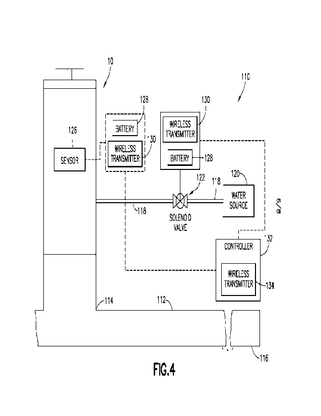
embodiments or aspects,
the drain 10 can include a resilient member, such as a helical coil or spring,
operatively
connected to the drain member 12 and/or housing 20, that returns the drain
member 12 and/or
housing 20 to the retracted position when fluid pressure from fluid entering
the interior volume
36 through the inflow port 70 ceases. Alternatively, the drain member 12 and
housing 20 may
remain in an extended position when the actuator is in the non-active state
(i.e., when fluid is
no longer being pumped into the interior volume), at least until some external
force pushes the
drain member 12 and/or housing 20 back to a retracted position. For example, a
user (e.g., a
golf course maintenance worker) may manually push the drain member 12 and/or
housing 20
back to the retracted position after all water has drained from the bunker 2.
In other non-
limiting embodiments or aspects, the housing 20 or actuator may be double-
acting (e.g.,
capable of exerting a biasing force in both the proximal and distal
directions), such that once
water is drained from the bunker 2, the housing 20 exerts a proximally
directed biasing force
on the drain member 12 causing the drain member 12 and/or housing 20 to return
to the
retracted position.
[0083] For example, in order to actively force the drain 10 back to the
retracted position, the
drain 10 can include a second inflow port 76 for filling the second volume 36b
with fluid from
the fluid source. The second inflow port 76 can be a fluid channel passing
through the sidewall
26 of the housing 20 and including an opening to the second volume 76 near the
top 22 of the
housing 20. While not shown in FIGS. 2A-2C, a proximal end of the second
inflow port 76
can be connected to the fluid source through a fluid supply line to supply the
fluid to the second
17
CA 03192164 2023- 3-8
WO 2022/056280
PCT/US2021/049893
volume 36b of the housing 20. For example, as shown by arrows A4 (in FIGS. 2B
and 2C),
the fluid can pass through the second inflow port 76 into the second volume
36b at a position
above the piston 72. As the second volume 36b fills with the fluid, the piston
72 moves in a
proximal or second (e.g., downward) direction causing the drain 10 to move
from the extended
position towards the retracted position. Further, at least partially filling
the second volume 36b
can cause fluid contained in the first volume 36a to pass back through the
first inflow port 70,
thereby allowing the drain 10 to retract.
[0084] In some non-limiting embodiments or aspects, the drain 10 further
includes a cap 42
movable between a retracted position (shown in FIGS. 2A and 2B), in which the
cap 42 covers
the open top 22 of the drain member 12, and an extended position (shown in
FIG. 2C) in which
the cap 42 is separated from the open top 22 of the drain member 12 so that
water flows past
the cap 42 into the drain member 12, as shown by arrows A5 (in FIG. 2C). The
cap 42 can be
a substantially flat structure, such as a disk, sized to fit over and seal the
open top 14 of the
drain member 12. For example, the cap 42 can have a diameter D3 of about 3.5
inches to about
10.0 inches. In general, the cap 42 includes a flat surface without
protrusions, raised portions,
ridges, gaps, openings, or other discontinuities, so that the drain 10 can be
easily pushed
through the sand or dirt of the bunker 2 as the drain 10 extends and retracts.
As previously
described, complex structures, such as protrusions or ridges, can be difficult
to move through
the sand or dirt. Further, abrasive materials, such as sand, silt, or dirt,
can become trapped in
openings or gaps, damaging the drain 10. Accordingly, devices with flat and
smooth surfaces
are believed to have a longer operational life compared to devices including
irregular, bulging,
or protruding surfaces or structures.
[0085] The cap 42 can be connected to and/or integrated with a linear actuator
or drive
member configured to move the cap 42 between the retracted position and the
extended
position. For example, the actuator can include a cap housing 48 mounted, for
example, to the
top plate 28 of the drain housing 20. The cap housing 48 can enclose a volume
50 and a cap
piston 52 configured to move through the cap housing 48 to extend or retract
the cap 42. The
actuator can further include a first inflow channel 44 or port that provides
fluid into the interior
volume 50 to push the cap piston 52 through the housing 48 in an upward
direction, thereby
causing the cap 42 to move to the extended position. The actuator can further
include a second
inflow channel 46 or port for providing fluid to the interior volume 50 of the
cap housing 48
above the piston 52, which forces the piston 52 in a downward direction to
retract the cap 42.
While not shown in FIGS. 2A-2C, proximal ends of the first inflow channel 44
and/or the
second inflow channel 46 can be connected to the fluid source by fluid supply
lines for
18
CA 03192164 2023- 3-8
WO 2022/056280
PCT/US2021/049893
providing the fluid to the inflow channels 44, 46 or ports. The fluid supply
lines can include
one or more manually or automatically actuated valves that open or close to
control movement
of the cap 42 between the retracted position and the extended position.
[0086] The cap actuator can be activated in the same manner as the actuator
that extends and
retracts the drain housing 20. For example, the drain cap actuator can be
sensitive to water
pressure or moisture. When either an increase in pressure or moisture is
detected, the drain cap
actuator can automatically activate valves in the fluid supply lines causing
fluid to enter the
interior volume 50 of the cap housing 48 through the first channel 44 or the
second channel 46.
In other non-limiting embodiments or aspects, the drain cap actuator can be
configured to
activate in conjunction with movement of the housing 20 and drain member 12.
For example,
the drain cap 42 can be configured to move to the extended position when
movement of the
drain member 12 and/or housing 20 is detected or, preferably, immediately
after movement of
the drain member 12 and/or housing 20 is completed, indicating that the drain
10 is in the
extended position. Similarly, the drain cap 42 can be configured to
automatically retract when
the drain member 12 is retracted (e.g., moves in a proximal direction, shown
by arrow A2 in
FIGS. 2B and 2C) and/or when the fluid begins to flow through the first inflow
port 70 at the
bottom 24 of the housing 20.
[0087] In use, after the drain 10 is moved to the extended position with the
top 22 of the
housing 20 above a surface of the sand (as shown in FIG. 2B), fluid is pushed
through the first
inflow channel 44 into the interior volume 50 of the cap housing 48. The fluid
contacts the
piston 52 causing the piston 52 to move in an upward direction (shown by arrow
A6) to move
the cap 42 to the extended position (shown in FIG. 2C). When extended, the
drain cap 42 can
be spaced apart from the top 22 of the housing 20 by a distance D4 (shown in
FIG. 2C). The
distance D4 can be from about 1.0 inch to about 4.0 inches. After water is
drained from the
bunker and the drain 10 is ready to move to the retracted position, fluid is
pumped through the
second inflow channel 46 collecting above the piston 52, which presses the
piston 52 in a
downward direction causing the cap 42 to return to the retracted position
(shown in FIGS. 2A
and 2C).
[0088] With continued reference to FIGS. 2A-2C, the drain 10 may be extended
and retracted
as follows. Initially, the drain 10 is in a retracted position (as shown in
FIGS. 1A and 2A),
where the housing 20 is retracted meaning that the annular sleeve 32 is in a
substantially relaxed
or un-stretched state. Also, the drain cap 42 is refracted and any biasing
member, such as a
spring (if present), is in an unbiased position. In this position, the bunker
2 is substantially dry
and the open top 14 of the drain member 12 and drain cap 42 are buried an
acceptable depth
19
CA 03192164 2023- 3-8
WO 2022/056280
PCT/US2021/049893
below the surface 9 of the sand 8. As water collects in the bunker 2, the
drain 10 can be
manually or automatically activated. For example, a user (golf course
maintenance worker)
may cause a valve in a fluid supply line of a water irrigation or sprinkler
system to open,
causing water to flow into the interior volume 36 of the housing 20 through
the first inflow port
70. In other non-limiting embodiments or aspects, a valve may be automatically
opened or an
inflating device (e.g., a device that provides compressed gas to the interior
volume 36 of the
housing 20) may be automatically activated causing fluid to pass into the
interior volume 36
defined by the housing 20 to at least partially fill the interior volume 36.
The housing 20 is
shown in a filled or extended position in FIG. 2B. In this filled or extended
position, the top
22 of the housing 20 and the top 14 of the drain tube or drain member 12
extend above the
surface 9 of the sand 8. The extended annular sleeve 32 of the housing 20 may
exert a biasing
force in a proximal direction against the housing 20. In FIG. 2B, the drain
cap 42 remains in
the retracted position.
[0089] After the housing 20 is at least partially filled, thereby moving the
drain cap 42 above
the surface 9 of the sand 8, the drain cap 42 can be extended by, for example,
causing fluid to
flow into the cap housing 48 through the first inflow channel 44, which pushes
the cap 42 to
the extended position, as shown in FIG. 2C. Once the drain cap 42 is extended,
water can flow
into the drain tube or drain member 12 through the open inflow portion or top
14 of the drain
member 12. The water flows through the drain tube or drain member 12, out of
the open bottom
of the drain member into the drainpipe or drain conduit 4, and away from the
drain 10 and
bunker 2. Once the water collected in the bunker 2 has drained, the drain cap
42 can be
retracted by, for example, causing fluid to pass into the interior volume 50
of the cap housing
48 through the second inflow channel 46 to push the drain cap 42 to its
retracted position
(shown in FIG. 2B). Once the drain cap 42 returns to the retracted position,
the drain housing
20 can be made to return to its retracted position. For example, as previously
described, fluid
can be introduced into the second volume 36b defined by the housing 20, which
causes the
piston 72 to retract through the housing 20 towards the bottom 24 of the
housing 20.
Movement of the piston 72 towards the bottom 24 of the housing 20 causes the
annular sleeve
32 to retract or return to its un-stretched state. As previously described, a
biasing force on the
sleeve 32 may assist in causing the sleeve 32 to return to the retracted
position or un-stretched
position, thereby allowing the drain 10 to return to the retracted position
(shown in FIG. 2A).
In other non-limiting embodiments or aspects, the drain 10 can include the
resilient member,
such as the spring, that provides an additional retracting force on the
housing 20 or drain
member 12.
CA 03192164 2023- 3-8
WO 2022/056280
PCT/US2021/049893
Drainage systems
[0090] With reference to FIGS. 3 and 4, drainage systems 110 for a golf course
bunker or for
any other pit, depression, or low-lying area includes a plurality of any of
the exemplary
extendable drains 10 described herein. As previously described, the extendable
drains 10
include the drain tube or drain member 12 including the inflow portion or top
14 and the
outflow portion or bottom 16; the housing 20 that encloses the drain tube or
drain member 12;
and the inflow ports 70, 76 for introducing fluid into the interior volume 36
of the housing 20
to move the drains 10 between the retracted positions and the extended
positions. The drainage
system 110 can further include an arrangement of conduits 112 including inflow
portions 114
connected, for example, to vertical drain conduits 60 and an outflow
portion(s) 116 opposite
the inflow portions 114. The outflow portion(s) 116 can be configured to expel
water to, for
example, a sump, storm drain, golf course water feature (e.g., a pond or
stream), or to any other
convenient location. As shown in FIG. 3, the arrangement of conduits 112 can
include a single
substantially horizontal segment connected to multiple drains 10 for
transporting the water
collected through the drains 10 away from the bunker 2 towards the outflow
portion 116 of the
arrangement of conduits 112. In other non-limiting embodiments or aspects, the
system 110
can include multiple segments connected to different drains 10. Each of the
multiple segments
may extend to a common outflow location. In either case, water in the bunker
flows, as shown
by arrows A7, through the drains 10 and vertical drain conduits 60 to the
horizontal conduits
112. Water then flows through the horizontal conduits 112, as shown by arrow
AS, to the
outflow portion 116.
[0091] In some non-limiting embodiments or aspects, the drainage system 110
further
includes an arrangement of water supply conduits 118 extending from a water
source 120 to
the drains 10 for delivering water to the drain 10. The system 110 may further
include valve(s)
122 positioned along the water supply conduits 118 or, for example, between
the water supply
conduits 118 and the drains 10 for controlling the flow of water to the
interior volumes 36 of
the housings 20. When the valve(s) 122 are in an open position, water flows
from the water
source 120, through the water supply conduits 118, and into the housings 20.
As discussed
previously, as the housings 20 are at least partially filled by fluid, the
housings 20 and drain
members 12 move to their extended positions. When the valve(s) 122 are in a
closed position,
water flow to the housings 20 stops, causing the annular sleeve 32 to retract,
which allows the
drain member 12 and housing 20 to return to their refracted positions. With
specific reference
to FIG. 3, in some non-limiting embodiments or aspects, the valve(s) 122 are
manually
operated. For example, the valve(s) 122 can be connected to a knob, dial,
handle, or lever 124
21
CA 03192164 2023- 3-8
WO 2022/056280
PCT/US2021/049893
that can be twisted or otherwise engaged by a user (e.g., golf course
maintenance crew) to open
or close the valves 122 to control water flow. In other non-limiting
embodiments or aspects,
the valves 122 can be electro-mechanical valves, such as electrically powered
solenoid valves,
that can be actuated (e.g., opened or closed) by, for example, a remote
control device, such as
a computer or smart phone.
[0092] With specific reference to FIG. 4, in some non-limiting embodiments or
aspects, the
drainage system 110 is an automated electronic activation system configured to
automatically
move the drains 10 between the retracted and extended positions. The automated
drainage
system 110 includes one or more sensors 126 configured to detect information
indicating that
water is collecting in the bunker 2. For example, the sensor 126 can be a
water pressure sensor
configured to detect increased pressure indicating that water is collecting in
the bunker 2. In
other non-limiting embodiments or aspects, the sensor 126 can be a moisture
sensor configured
to detect moisture or water in proximity to the sensor 126. In other non-
limiting embodiments
or aspects, the sensor 126 can be an optical or light (e.g., radiance) sensor
that detects changes
in light intensity caused when water collects in the bunker 2. The sensor 126
can be positioned
on one of the drains 10, as shown in FIG. 4, or at any other convenient
location in proximity to
the drains 10 and bunker 2. In some non-limiting embodiments or aspects, the
sensors 126 are
independent electronic devices configured to collect and process data. In some
non-limiting
embodiments or aspects, the sensors 126 can include a power source, such as a
battery 128 for
providing power for the sensor 126. The sensors 126 can further include a
wireless data
transmitter 130 for transmitting collected data to remote devices.
[0093] The sensors 126 are electrically connected to and/or in electronic
communication with
a controller 132, such as a computer processor. For example, the controller
132 may include a
wireless transmitter 134 that receives information from the sensors 126 and
transmits
instructions to other devices. In some non-limiting embodiments or aspects,
the controller 132
may also be electrically connected to the valve(s) 122, such as solenoid
valves, located by the
drains 10, along the water supply conduits 118, or at the water source 120. As
in previous
embodiments or aspects, the solenoid valve(s) 122 are configured to open to
allow water to
flow from the water source 120 to the drains 10. The solenoid valve 122 can
include or be
connected to a wireless transmitter 134 for receiving instructions from the
controller 132 and
a battery 128 for providing power for the transmitter 134 and for electro-
mechanical devices
for opening and closing the valve 122.
[0094] In some non-limiting embodiments or aspects, the controller 132 is
configured to
receive and process signals from the sensors 126. For example, received
signals can be
22
CA 03192164 2023- 3-8
WO 2022/056280
PCT/US2021/049893
processed to determine ambient pressure (e.g., water or air pressure) in
proximity to the sensors
126. In other non-limiting embodiments or aspects, the signals can be
processed to determine
whether moisture is present in proximity to the sensors 126 or to determine
light (radiance) in
proximity to the sensors 126. Processing the received signals can also include
analyzing the
detected pressure, moisture, and/or optical information to determine whether
water is collecting
in the bunker 2. The controller 132 is further configured to cause the
extendable drains 10 to
move to the extended position when the received and processed signals from the
sensors 126
indicate that water is collecting in the bunker 2. In some non-limiting
embodiments or aspects,
as previously discussed, the controller 132 activates or causes the solenoid
valves 122 to move
to the open position, which allows water to flow into the interior volume 36
of the housing 20
of the drains 10. In other non-limiting embodiments or aspects, the controller
132 may be
configured to cause an electrical component of the actuator to turn on or, for
example, can
cause air to flow into the housings 20 of the drains 10 from an associated
bellows or reservoir
(e.g., a compressed air canister).
Extendable sprinklers
[0095] With reference to FIGS. 5A-6, an extendable sprinkler 210 is shown that
transitions
from a retracted position (shown in FIG. 5A), when not in use, to an extended
position (shown
in FIG. 5B), when water is being expelled from the sprinkler 210. When the
sprinkler 210 is
in the retracted position, all or nearly all portions of the sprinkler 210 are
below ground level,
meaning that it does not interfere with and cannot be damaged by lawnmowers or
other vehicles
and does not present a tripping hazard for, for example, golf course users.
[0096] As shown in FIGS. 5A and 5B, the extendable sprinkler 210 includes a
support
conduit 212 including an inflow portion 214 configured to be connected to a
water supply
conduit (not shown in FIGS. 5A and 5B) and an opposing outflow portion 216.
The support
conduit 212 is configured to be at least partially buried below ground, such
that the outflow
portion 216 is at or slightly above ground level. The support conduit 212 is a
sufficient length
to extend from the water supply conduit (not shown in FIGS. 5A and 5B) to
ground level and
can have a diameter D5 of from about 0.25 inch to about 1.5 inches. The
support conduit 212
can be formed from any materials commonly used for plumbing pipes and
fixtures, such as
metal or plastic (e.g., PVC).
[0097] The sprinkler 210 further includes a riser conduit 218 extending
through an opening
220 of the outflow portion 216 of the support conduit 212. The riser conduit
218 can have a
diameter D4, which is narrower than the support conduit 212, so that the riser
conduit 218 can
23
CA 03192164 2023- 3-8
WO 2022/056280
PCT/US2021/049893
be positioned in and at least partially enclosed by the support conduit 212.
Further, the riser
conduit 218 is sized and configured to slide through the opening 220 of the
support conduit
212. A length L3 of the riser conduit 218 is dependent upon the length of the
support conduit
212 and an intended extension height of the sprinkler 210 (e.g., the height
that the sprinkler
210 extends above the ground when in the extended position). In some non-
limiting
embodiments or aspects, the length L3 of the riser conduit 218 can be from
about 3.0 inches to
about 12 inches, and the diameter D4 of the riser conduit 218 can be from
about 0.25 inch to
about 1.0 inch. The riser conduit 218 can include a proximal flange 222 on the
proximal end
of the riser conduit 218, a distal flange 224 on the distal end of the conduit
218, and a sidewall
extending between the flanges 222, 224.
[0098] The sprinkler 210 can further include a sprinkler nozzle 226 connected
to the riser
conduit 218 configured to expel water that passes through the support conduit
212 and the riser
conduit 218 to the sprinkler nozzle 226. In some non-limiting embodiments or
aspects, the
nozzle 226 can be a perforated cover or disk extending over an open distal
portion of the riser
conduit 218. In other non-limiting embodiments or aspects, the open distal
portion of the riser
conduit 218 includes, for example, a threaded portion configured to engage
with corresponding
threads of a sprinkler nozzle 226 or sprinkler head for attaching the
sprinkler nozzle 226 or
sprinkler head to the riser conduit 218.
[0099] As shown in FIGS. 5A and 5B, the extendable sprinkler 210 further
includes an
annular inflatable bladder 228 including a proximal portion 230 connected to
the support
conduit 212, a distal portion 232 connected to the riser conduit 218 or
sprinkler nozzle 226,
and a sidewall 234 extending between the proximal portion 230 and the distal
portion 232. For
example, the proximal portion 230 of the inflatable bladder 228 can be
connected to the outflow
portion 216 of the support conduit 212. The distal portion 232 of the
inflatable bladder 228
can be connected to a peripheral edge of the distal flange 224 of the riser
conduit 218.
[0100] The inflatable bladder 228 is positioned to surround the outflow
portion 216 of the
support conduit 212 and portions of the riser conduit 218. Particularly, the
inflatable bladder
228 is configured to enclose the opening 220 on the distal end of the support
conduit 212 to
prevent water, debris, and other materials from passing into the interior of
the sprinkler 210
and into the support conduit 212, which may contaminate and clog portions of
the sprinkler
210, restrict water flow through the sprinkler 210, and/or prevent the
sprinkler 210 from
extending and retracting as intended. The inflatable bladder 228 extends
axially causing the
riser conduit 218 to move from the retracted position (shown in FIG. 5A) to
the extended
position (shown in FIG. 5B) under force of water flowing through the support
conduit 212 and
24
CA 03192164 2023- 3-8
WO 2022/056280
PCT/US2021/049893
the riser conduit 218. For example, the inflatable bladder 228 may have a
length L4 in the
retracted position (FIG. 5A) and a length L5 when extended (FIG. 5B). The
inflatable bladder
228 can be similar in shape and construction to elastomeric sleeves described
previously. For
example, the inflatable bladder 228 can be formed from flexible and/or
stretchable elastomeric
materials, such as silicone and/or natural or synthetic rubbers.
[0101] In use, water flowing into the extendable sprinkler 210 through the
support conduit
212 passes into the inflatable bladder 228 through the opening 220, which
causes the bladder
228 to inflate and produce pressure on the distal flange 224 to push the riser
conduit 218 in the
distal direction, shown by arrow A9. In some non-limiting embodiments or
aspects, the
proximal flange 222 can be sized so that some of the water flowing through the
support conduit
212 contacts the proximal flange 222, which provides an additional force for
pushing the riser
conduit 218 in the distal direction, shown by arrow A10.
[0102] In some non-limiting embodiments or aspects, the sprinkler 210 further
includes a
resilient member, such as a helical spring 236, mounted between the riser
conduit 218 and the
support conduit 212. The helical spring 236 is shown in an extended or
unbiased state in FIG.
5A and in a compressed or biased state in FIG. 5B. In the compressed state,
the helical spring
236 exerts a biasing force in a proximal direction (shown by arrow Al 0 in
FIG. 5B) on the riser
conduit 218 to retract the riser conduit 218. In use, when water is turned
off, the bladder 228
begins to deflate. As the bladder 228 deflates, since there is no longer a
distally directed force
on the riser conduit 218, the force of the helical spring 236 causes the riser
conduit 218 and
sprinkler nozzle 226 attached thereto to return to the retracted position
(shown in FIG. 5A).
Irrigation or sprinkler systems
[0103] With reference to FIG. 6, any of the exemplary extendable sprinklers
210 of the
present disclosure can be integrated in an irrigation or sprinkler system 310,
such as an
irrigation or sprinkler system for a golf course, garden, lawn, or other
outdoor landscape
environment. As discussed previously, using extendable and retractable
sprinklers 210 can
prevent lawnmowers and other vehicles from damaging the sprinklers 210. In
some non-
limiting embodiments or aspects, the sprinkler system 310 includes the
extendable sprinklers
210. The extendable sprinklers 210 can include the support conduit 212, which
is completely
or substantially completely buried in the ground, and the riser conduit 218
configured to be
retracted in the support conduit 212 when not in use and to extend from the
open distal end 220
of the support conduit 212 when water is supplied to the sprinkler 210. The
sprinklers 210
further include the nozzle 226 connected to or integrally formed with the
riser conduit 218.
CA 03192164 2023- 3-8
WO 2022/056280
PCT/US2021/049893
The sprinklers 210 further include the annular inflatable bladder 228
enclosing portions of the
support conduit 212 and riser conduit 218.
[0104] In some non-limiting embodiments or aspects, the sprinkler system 310
further
includes an arrangement of water supply conduits 312 extending from a water
source 314 to
the sprinklers 210. For example, outflow portions of the water supply conduit
312 can be
connected to the support conduits 212 of the sprinklers 210. As discussed
previously, water
flows through the support conduits 212 into the inflatable bladder 228 and
forces the riser
conduits 218 to move to the extended positions. Water is then expelled from
the riser conduits
218 through the sprinkler nozzles 226. The riser conduits 218 return to the
retracted position,
due to the proximally directed force of the helical spring 236, when water is
not flowing into
the support conduits 212.
[0105] The system 310 can further include a valve 318 for controlling movement
of water
from the water source 314 through the water supply conduits 312. As in
previous non-limiting
embodiments or aspects, the valve 318 can be a manually actuated valve, such
as a tap or
sillcock, which is controlled by a handle, knob, or lever 320. In other non-
limiting
embodiments or aspects, the valve 318 can be an electromechanical device, such
as a solenoid
valve 318, which can be remotely controlled by, for example, a wireless remote
control device
operated by a user. In other non-limiting embodiments or aspects, the solenoid
valve 318 can
be in electronic (e.g., wired or wireless) communication with a control system
or controller
configured to provide instructions causing the solenoid valve 318 to open and
close. For
example, the controller can be configured to cause the solenoid valve 318 to
open at preselected
times and for preselected durations according to a predetermined schedule. In
other non-
limiting embodiments or aspects, the system 310 can include sensors 322 for
detecting
information for determining when the valve 318 should be opened. For examples,
the sensors
322 may be configured to detect light intensity (radiance) or temperature so
that the water turns
on at night (e.g., in low light) or at cooler times of the day (e.g.,
determined based on
temperature measurements).
[0106] In some non-limiting embodiments or aspects, the drainage system 110
and sprinkler
system 310 may be connected together and/or may share any of the mechanical
and electrical
components described herein. For example, a combined system may be constructed
where an
arrangement of water supply conduits 118, 312 transports water to drains 10
and sprinklers
210. The combined system could include a series of valves 122, 318 for
controlling flow of
water from the water source 120, 314 to the drains 10 and sprinklers 210, so
that the drains 10
and sprinklers 210 are extended and in use at appropriate times. In
particular, the valves 122,
26
CA 03192164 2023- 3-8
WO 2022/056280
PCT/US2021/049893
318 of the combined system may be manually controlled by the same remote
control device or
automatically controlled based on instructions from a common controller (e.g.,
a central
computer or computer network). The common controller may be configured to
cause the drains
to extend to drain water from the bunkers when it is raining and/or when water
is detected
collecting in the bunkers. The common controller may be configured to cause
the sprinklers
210 to extend when it is dry and, in particular, during times when the golf
course or other
landscape environment is not is use (e.g., at night).
[0107] Although the disclosure has been described in detail for the purpose of
illustration
based on what is currently considered to be the most practical and preferred
embodiments, it is
to be understood that such detail is solely for that purpose and that this
disclosure is not limited
to the disclosed embodiments, but, on the contrary, is intended to cover
modifications and
equivalent arrangements. Furthermore, it is to be understood that the present
disclosure
contemplates that, to the extent possible, one or more features of any
embodiment can be
combined with one or more features of any other embodiment.
27
CA 03192164 2023- 3-8