Note: Descriptions are shown in the official language in which they were submitted.
1
ASSEMBLY OF A MOTOR FOR A TUBE OF A SCREEN AND A SET OF
ADAPTABLE PLUGS FOR ENGAGING THE INNER SURFACE OF THE TUBE
The present invention relates to an assembly of a motor for a tube of a
screen, for example a roller blind tube, and a set of plugs for engaging an
inner
surface of the tube, wherein the set of plugs comprises a drive plug for
driving the
tube, which drive plug is arranged to be connected to a drive shaft of the
motor,
wherein the set of plugs comprises a crown plug, which crown plug is arranged
to
be connected to an outer end of the motor for forming a first bearing at a
first outer
end of the tube, wherein the set of plugs comprises an end plug arranged to be
inserted into the tube at a second outer end of the tube for forming a second
bearing, wherein each plug is provided with adapter means for adapting the
outer
diameter of the plug to the inner diameter of the tube.
The assembly according to the invention provides the possibility to provide a
universal motorized control for screen tubes. The plugs have adaptive outer
dimensions that allow the assembly to be used for a wide variety of known
screens
having tubes with different dimensions. It is especially suitable as a
retrofit kit to
motorize any known roller blind system.
According to a preferred embodiment the adapter means comprise one or
more engaging elements for engaging the inner surface of the tube that are
movable between a minimal position in which the dimensions of the outer
diameter
of the plug are at a minimum and an extreme position in which the dimensions
of
the outer diameter of the plug are at a maximum. By using engaging elements,
the
optimal dimensions for the outer diameter of the plug can be easily set as
only a
few engaging elements suffice.
According to a first preferred embodiment the engaging elements are
slidable over the plug and the adapter means further comprise pushing means to
push the engaging elements radially outward towards the extreme position.
Advantageously hereby a stepless adaptation of the dimensions of the plug
outer
diameter is achieved.
According to an elegant, preferred embodiment one or more of the plugs
comprise a base part and a cover part that is slidable over the base part,
wherein
the cover part and the base part enclose the engaging elements and the cover
part
forms part of the pushing means. The integration of the engaging elements in
the
plug renders this embodiment compact and robust. The pushing cover part
renders
Date recue/Date received 2023-03-06
2
this embodiment suitable for plugs that are hard to access for a user, such as
the
drive plug and the end plug.
According to a practical preferred embodiment the pushing means further
comprise pretensioning means, such as a spring. Preferably the adapter means
.. further comprise operating means for the pretensioning means. In a first
variant the
pretensioning means are arranged to pretension the engaging elements in the
minimal position and the operating means comprise retaining means that are
arranged to retain the pretensioning means in a pressed position and the
operating
means are arranged to release the pretensioning means. The first variant is
.. perfectly suitable for the drive plug and allows a user to release the
pretensioning
means when the drive plug is at least partly inserted in the tube. The outer
diameter
of the drive plug will then automatically adapt to the inner diameter of the
tube. In a
second variant the operating means are arranged to move the engaging elements
towards the extreme position against the force of the pretensioning means. In
the
second variant the operating means may comprise a suitable tool, such as a hex
key or a screwdriver. The second variant is perfectly suitable for the end
plug and
allows a user to adapt the outer diameter of the end plug to the inner
diameter of
the tube when the end plug is at least partly inserted in the tube.
According to a second preferred embodiment the engaging elements are
provided on one or more inserts and the adapter means comprise connection
means for releasable connection of the inserts to the outer circumference of
the
plug in two or more different positions. The second embodiment is perfectly
suitable
for plugs that are accessible for a user, such as the crown plug.
In a first variant of the second preferred embodiment the inserts are open
rings. The rings allow for a simultaneous connection of all engaging elements
to the
plug and consequently for a fast adaptation of the outer diameter of the plug
to the
inner diameter of the tube.
In a second variant of the second preferred embodiment, the inserts are
pins. The position of the pins can be easily changed to adapt the outer
diameter of
the plug to the inner diameter of the tube. Several pins of different sizes
can be
provided.
In an optimal preferred embodiment, the engaging elements are provided
with a ridge on top. Generally on the interior of many known screen tubes
irregularities are present, such as seams or edges. The ridge provides a more
universal fit and in general a better grip.
Date recue/Date received 2023-03-06
3
Preferably the adapter means comprise three engaging elements.
In a practical preferred embodiment the engaging elements are radially
protruding ribs.
The invention will now be described in more detail with reference to the
figures, in which
Figure 1 shows a schematic view of a first preferred embodiment of an
assembly according to the invention;
Figure 2A shows a schematic view of an adaptable drive plug as part of the
assembly of figure 1;
Figure 2B shows the adaptable drive plug of figure 2A with exploded parts;
Figure 2C schematically shows a longitudinal section through the adaptable
drive plug of figure 2A;
Figure 2D schematically shows a longitudinal section through the adaptable
drive plug in a different position;
Figure 2E shows a cross section through the adaptable drive plug of figure
2A;
Figure 2F shows a cross section through a first variant of the adaptable
drive plug as part of the assembly according to the invention;
Figure 2G shows a cross section through a second variant of the adaptable
drive plug as part of the assembly according to the invention;
Figure 3A shows a schematic view of an adaptable end plug as part of the
assembly of figure 1;
Figure 3B shows the adaptable end plug of figure 3A with exploded parts;
Figure 3C schematically shows a longitudinal section through the adaptable
end plug of figure 3A;
Figure 3D schematically shows a longitudinal section through the adaptable
end plug in a different position ;
Figure 3E shows a cross section through the adaptable end plug of figure
3A;
Figure 4A shows a schematic view of a first preferred embodiment of an
adaptable crown plug as part of the assembly of figure 1;
Figure 4B shows the adaptable crown plug of figure 4A with exploded parts;
Figure 5A shows a schematic view of a second preferred embodiment of an
Date recue/Date received 2023-03-06
4
adaptable crown plug as part of the assembly according to the invention; and
Figure 5B shows the adaptable crown plug of figure 5A with exploded parts.
The same components are designated in the different figures with the same
reference numerals.
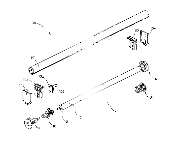
Figure 1 schematically shows an exploded view of a preferred embodiment
of an assembly 1 according to the invention to motorize any type of screen
having a
tube. As an example, a roller blind system 100 is shown having a roller blind
tube
101 to which a flexible sheet member or roller curtain is to be attached in a
conventional manner.
The assembly 1 comprises a tubular motor 2 and a set of plugs 10, 20, 30
for engaging the inner surface of the tube 101.
The set of plugs comprises a drive plug 10 for driving the tube, which is
arranged to be connected to a drive shaft 3 at a first outer end of the
tubular motor
2. The set of plugs comprises a crown plug or crown 30 that is arranged to be
connected to a second outer end 4 of the tubular motor 2. In the embodiment
shown the crown plug 30 could first be placed over the drive shaft 3 at the
first
outer end of the tubular motor 2 and could then be moved towards the second
outer
end 4. The tubular motor 2 provided with the drive plug 10 and preferably also
provided with the crown 30 is to be inserted at one end of the tube 101, for
example
at the right end of the tube 101 in figure 1.
The set of plugs comprises an end plug 20 arranged to be inserted into the
tube 101 at an opposite end of the tube 101, for example at the left end of
the tube
101 in figure 1.
According to the invention the drive plug 10, the end plug 20 and the crown
are all provided with adapter means for adapting the outer diameter of the
plug
to the inner diameter of the tube 101.
Suitable devices for mounting the roller blind tube 101 on a surface, such as
30 a wall, window frame or a ceiling, having releasably attachable mounting
brackets
and bracket connectors or shaft holders are known in the relevant field.
Particularly
suitable is a known device of the same applicant that is described in the
abovementioned European patent application EP2933428, incorporated herein by
reference.
Said known device comprises two bracket connectors 102 that are arranged
Date recue/Date received 2023-03-06
5
to be attached at the outer ends of the roller blind tube 101. The bracket
connectors
102 are arranged for releasable attachment to mounting brackets 103 for
mounting
the roller blind system on a surface. Optionally end caps 104 are mounted over
the
mounting brackets 103 in the mounted state of the roller blind system 101. One
of
the bracket connectors 102 is visible and provided with a bearing pin 105 for
insertion in the end plug 20.
Figures 2A, 2B, 2C and 2D show a preferred embodiment of the adaptable
drive plug 10 in more detail. Figure 2A shows a schematic view of the
adaptable
drive plug 10 in the extreme position in which the dimensions of the outer
diameter
of the drive plug 10 are at a maximum. Figure 2B shows an exploded view of the
adaptable drive plug 10. Figure 2C schematically shows a cross section in
longitudinal direction through the adaptable drive plug 10 in the extreme
position
shown in figure 2A. Figure 2D schematically shows a cross section in
longitudinal
direction through the adaptable drive plug 10 in the minimal position in which
the
dimensions of the outer diameter of the drive plug 10 are at a minimum.
According to the invention the adaptable drive plug 10 comprises first
adapter means that define the outer dimensions of the adaptable drive plug 10.
In
the preferred embodiment shown the first adapter means comprise a number of
engaging elements, preferably ribs 13, that are movable over the outer
circumference of the adaptable drive plug 10 between the minimal position and
the
extreme position.
The adaptable drive plug 10 comprises a base part 11 and a cover part 12
that is slidable over the base part 11 in longitudinal direction thereof. The
cover part
12 and the base part 11 enclose the ribs 13. The adaptable drive plug 10
further
comprises a spring 14 that is enclosed by the cover part 12 and the base part
11.
The cover part 12 is arranged to push the ribs 13 over the base part 11 under
the
action of the spring 14 out of a minimal position towards an extreme position.
In the
preferred embodiment shown the cover part 12 comprises a number of
longitudinal
openings 16A to accommodate the ribs 13. Each longitudinal opening 16A has a
short edge 16 that is arranged to abut against a short side of one of the ribs
13.
In the preferred embodiment shown the base part 11 is provided with a
number of guiding elements, preferably wings 15, corresponding to the number
of
ribs 13. The ribs 13 have first, generally oblique guiding surfaces 13A and
the wings
15 have second, generally oblique guiding surfaces 15A. The first and second
guiding surfaces 13A, 15A are mating surfaces that facilitate sliding of the
ribs 13 in
Date recue/Date received 2023-03-06
6
a stepless manner between the minimal position (shown in figure 2D) and the
extreme position (shown in figure 2C).
Preferably the ribs 13 are provided with ridges 13B to form the contact area
with the inner surface of the tube 101.
In the preferred embodiment shown the number of ribs 13 and wings 15 is
three. Preferably the ribs 13 lie substantially on an imaginary circle.
In the preferred embodiment the ribs 13 are distributed unevenly over the
circumference and the angles between adjacent ribs increase in clockwise
direction.
This can be seen in figure 2E showing a cross section through the adaptable
drive
plug 10 in the extreme position. Herein the angle al is substantially 110
degrees,
the angle 02 is substantially 120 degrees and the angle 03 is substantially
130
degrees. An asymmetrical distribution of the ribs allows for finding a fit by
rotating
the adaptable plug in a tube having an irregular interior surface.
Figure 2F shows a cross section through a first variant of the adaptable
drive plug as part of the assembly according to the invention. Herein the
angles al
and 03 are substantially equal at substantially 135 degrees, whereas the angle
02 is
substantially 90 degrees. The larger angles provide a larger fitting area.
Figure 2G shows a cross section through a second variant of the adaptable
drive plug as part of the assembly according to the invention. In the second
variant
the ribs 13 are distributed substantially evenly over the circumference. The
angles
al, 02 and 03 are substantially equal at substantially 120 degrees. A
symmetrical
distribution of the ribs works well with tubes having a smooth interior
surface.
The base part 11 has a nose piece 18 for accommodating the spring 14. A
locking ring 17 locks the spring 14 in place.
Preferably the spring 14 is arranged to pretension the cover part 22 in a
direction towards the base part 21. Preferably the adaptable drive plug 10 is
provided with operating means for the spring that comprise retaining means
that are
arranged to retain the spring 14 in inwardly pressed position thereby allowing
the
adaptable drive plug 10 to assume the minimal position. In the minimal
position the
adaptable drive plug 10 can be easily inserted in the tube 101. In figure 2B a
removable locking pin 19 is shown as an example of suitable retaining means.
Once the retaining means release the spring 14, these will force the ribs 13
radially
outwards until the ribs 13 engage with the inner surface of the tube 101. The
adaptable drive plug 10 is then in a position to transfer the torque from the
tubular
motor 2 onto the tube 101.
Date recue/Date received 2023-03-06
7
Figures 3A, 3B, 3C and 3D show a preferred embodiment of the adaptable
end plug 20 in more detail. Figure 3A shows a schematic view of the adaptable
end
plug 20 in an intermediate position. Figure 3B shows an exploded view of the
adaptable end plug 20. Figure 3C schematically shows a cross section in
longitudinal direction through the adaptable end plug 20 in the extreme
position.
Figure 3D schematically shows a cross section in longitudinal direction
through the
adaptable drive plug 10 in the position of figure 3A.
According to the invention the adaptable end plug 20 comprises second
adapter means that define the outer dimensions of the adaptable end plug 20.
In
the preferred embodiment shown the second adapter means comprise a number of
engaging elements, preferably ribs 23, that are movable over the outer
circumference of the adaptable end plug 20 between the minimal position and
the
extreme position.
The adaptable end plug 20 comprises a base part 21 and a cover part 22
that is slidable over the base part 21 in longitudinal direction thereof. The
cover part
22 and the base part 21 enclose the ribs 23. The adaptable end plug 20 further
comprises a spring 24 that is enclosed by the cover part 22 and the base part
21.
The cover part 22 is arranged to push the ribs 23 over the base part 21 by
operating
the bolt 29 against the action of the spring 24 out of a minimal position
towards an
extreme position (shown in figure 3C). In the preferred embodiment shown the
cover part 22 comprises a number of longitudinal openings 26A to accommodate
the ribs 23. Each longitudinal opening 26A has a short edge 26 that is
arranged to
abut against a short side of one of the ribs 23.
In the preferred embodiment shown the base part 21 is provided with a
number of guiding elements, preferably wings 25, corresponding to the number
of
ribs 23. The ribs 23 have first, generally oblique guiding surfaces 23A and
the wings
25 have second, generally oblique guiding surfaces 25A. The first and second
guiding surfaces 23A, 25A are mating surfaces that facilitate sliding of the
ribs 23 in
a stepless manner between the minimal position and the extreme position.
Preferably the ribs 23 are provided with ridges 23B to form the contact area
with the inner surface of the tube 101. Preferably the number of ribs 23 and
wings
25 is three.
Figure 3E shows a cross section through the adaptable end plug 20 in the
position of figure 3A. In the preferred embodiment shown the ribs 23 are
distributed
substantially symmetrically over the circumference of the end plug. The angles
ai,
Date recue/Date received 2023-03-06
8
02 and 03 are substantially equal at substantially 120 degrees and lie
substantially
on an imaginary circle. As an alternative an asymmetrical distribution of the
ribs 23
is possible, for example one of the distributions shown in figure 2E and 2F
for the
ribs of the drive plug.
The base part 21 has an inner space 28 for accommodating the spring 24.
The inner space 28 is accessible by operating means, for example a bolt 29
that
cooperates with a nut 27 to press or release the spring 24 and thereby change
the
position of the cover part 22 and the ribs 23.
Preferably the adaptable end plug 20 is first brought in the minimal position
in which it can be easily inserted in the tube 101. Preferably the spring 24
is
arranged to pretension the cover part 22 in a direction away from the base
part 21.
The operating means can be used to press the spring 24 inwards thereby forcing
the ribs 23 radially outwards until the ribs 23 engage with the inner surface
of the
tube 101. The adaptable end plug 20 is then in a position to hold the tube
101.
Figure 4A shows a schematic view of a first preferred embodiment of an
adaptable crown plug 30 as part of the assembly of figure 1. Figure 4B shows
the
adaptable crown plug 30 with exploded parts.
According to the invention the adaptable crown plug 30 comprises third
adapter means that define the outer dimensions of the adaptable crown plug 30.
The third adapter means comprise a number of engaging elements, preferably
ribs
33, that can be moved between a minimal position in which the dimensions of
the
outer diameter of the crown plug 30 are at a minimum and an extreme position
in
which the dimensions of the outer diameter of the crown plug 30 are at a
maximum.
The engaging elements are provided on one or more inserts for releasable
connection to the outer circumference of the plug.
In the first preferred embodiment the insert is a ring 34 provided with
engaging elements formed by a number of radially outwardly protruding ribs 33.
The
crown plug 30 comprises a tube part 31 and a flange part 39. The ring 34
comprises
connection means for releasable connection of the ring 34 in different
positions on
the tube part 31 the crown plug 30. The connection means preferably comprise
mating grooves 32 and tongues 35 that extend in circumferential direction over
the
outer surface of the tube part 31 of the crown plug 30 and over the opposing
inner
surface of the ring 34. The ring 34 is open and the outer ends 36 of the ring
34 pre-
clamp towards each other.
Preferably a set of rings, for example rings 34-1, 34-2, 34-3, is provided
Date recue/Date received 2023-03-06
9
having ribs 33-1, 33-2, 33-3 of different heights. The rings allow for a
simultaneous
connection of all engaging elements to the plug and consequently for a fast
adaptation of the outer diameter of the plug to the inner diameter of the
tube.
Preferably rows of grooves 32, each having a different depth, are provided
on the tube part 31. As such a stepwise adaptation of the outer dimensions of
the
crown plug 30 to the inner dimensions of the tube can be accomplished. The
connection means preferably further comprise first and second ring segments 37
and 38 having different inner diameters. The first ring segments 37 fit
between the
rows of grooves 32, whereas the second ring segments 38 fit over the rows of
grooves 32.
Figure 5A shows a schematic view of a second preferred embodiment of an
adaptable crown plug 40 as part of the assembly according to the invention.
Figure
5B shows the adaptable crown plug 40 with exploded parts.
In the second preferred embodiment the inserts are sets of pins 44, wherein
each pin is provided with a radially outwardly protruding rib 43. Preferably
different
sets of pins are provided having ribs of different heights. The crown plug 40
comprises a tube part 41 and a flange part 49.The tube part 41 and the pins 44
comprise connection means for releasable connection of the pins 44 in
different
positions on the tube part 41. The connection means preferably comprise mating
grooves 42 and tongues 45 that extend in radial direction from the tube part
41 of
the crown plug 40 and over the opposing sides of the pins 44.
Preferably the grooves 42 are arranged in rows, wherein adjacent grooves
in a row have different depths. As such a stepwise adaptation of the outer
dimensions of the crown plug 40 to the inner dimensions of the tube can be
accomplished.
The invention follows from the inventive thought to provide a universal
assembly for motorizing a large number of roller blind systems of different
manufacturers. The use of adapter means, with either integrated or releasably
connectable engaging elements, which can assume varying radial positions on
the
plug to adapt the outer diameter of the plug to the inner diameter of the
tube, makes
the universal assembly very suitable for the aftermarket.
The invention is of course not limited to the described and shown preferred
embodiments but extends to any embodiment falling within the scope of
protection
as defined in the claims and as seen in the light of the foregoing description
and
accompanying drawings.
Date recue/Date received 2023-03-06