Note: Descriptions are shown in the official language in which they were submitted.
WO 2022/090878
PCT/IB2021/059748
HOT FORGING PROCESS AND MOULD FOR CARRYING OUT SAID
PROCESS
***
DESCRIPTION
Field of the invention
In its most general aspect, the present invention refers to the technical
sector of
hot forging and, in particular, the invention relates to a hot forging process
and a mould
for carrying out the aforesaid process.
State of the art
As is known, hot forging is a process which provides for the deformation of a
preheated billet generally made of metal material, through a mould consisting
of two
half-moulds, so as to achieve a semi-finished product which replicates the
geometry of
the desired final product.
As far as the half-moulds are concerned, it should be stated that they have
respective recesses which are the negative of the final geometry of the semi-
finished
product to be achieved and, thus, a correct design of the mould, and therefore
of the
half-moulds, is necessary, since it is necessary to take into account aspects
such as: draft
angles; corner radii that must not be too small to allow the metal material to
flow across
the recess and fill the mould correctly; the so-called stock allowance which
must be
removed by subsequent mechanical machining operations; and the dimensional
shrinkage which undergoes the material used after cooling.
In this regard, a half-mould is generally composed of a die which contains the
recess corresponding to the negative of the piece to be moulded (impression)
and a
mould holder which contains a recess in which the die is housed. Sometimes a
half-
mould can be composed of a greater number of components, e.g. it can comprise
a die
made of various pieces, with an increase in the respective complexity of the
mould but
with considerable cost saving for its implementation.
The die, in fact, is usually made of a material which is more performing than
that
used for the mould holder, since it must be in direct contact with the hot
billet and since
it is subjected to very high stresses. The mould holder, on the other hand, is
not
- 1 -
CA 03192427 2023- 3- 10
WO 2022/090878
PCT/IB2021/059748
subjected to the same high stresses as the die and being very massive with
respect to the
same die, much is saved by using, for its implementation, a cheaper material
Generally,
a mould holder of the type considered here consists of a forged steel bloom
As far as the starting billet is concerned, it should be stated that it
generally has a
volume slightly higher than the volume of the mould recess, to ensure that
during the
forging process the material fills the entire mould recess, while the excess
material
comes out of the mould at the dividing line between the half-moulds and forms
burrs
which are removed at a later time.
In this respect, the forging process provides for a first step of heating the
material forming the billet, which plays a fundamental role because it allows
to bring
the material to be processed to a temperature higher than the
recrystallisation
temperature; thus, the material becomes more ductile and deformable allowing a
complete filling of the mould even for complex geometries.
There follows a forging step in which one of the two half-moulds, usually the
lower one, remains fixed while the other, usually the upper one, is lowered by
a press
which applies a pressure sufficient to deform the billet until the desired
geometry is
achieved. The presses can be mechanical or hydraulic and can generally apply
forces of
the order of hundreds of tons, depending on the volume of the piece to be
moulded.
Once the forging step has been completed, the temperature of the semi-finished
product inside the mould is high and the mechanical properties of the semi-
finished
product are poor, so that it is necessary to wait for a minimum time interval
during
which the mould removes heat from the semi-finished product until it reaches
sufficiently low temperatures, such as not to cause distortions during the
subsequent
ejection step.
In this regard, to increase the heat exchange, in the half-moulds it is also
possible to provide for cooling channels in which water, which continuously
removes
heat, circulates.
The mould is then opened by separating the two half-moulds from each other.
When the mould is opened, the semi-finished product generally remains integral
with
the upper half-mould from which it is detached through suitable ejectors which
are only
- 2 -
CA 03192427 2023- 3- 10
WO 2022/090878
PCT/IB2021/059748
cylinders embedded in the half-mould which push on the semi-finished product.
Hot forging processes can be carried out on many families of metal alloys,
including steels, copper alloys, aluminium alloys or chromium or nickel
superalloys.
With respect to other processes provided in the known art, a hot forging
process
allows, thanks to the hot forging step, to achieve several advantages as
regards the
mechanical properties of the final product.
For example, through the deformation and the high pressures applied, all the
porosities present in the material are closed.
Moreover, since during the first heating step, the crystallisation temperature
of
the material is exceeded, after forging, the semi-finished product can be
subjected to
quick cooling so as to make the micro-structure finer.
Furthermore, through the deformation due to the forging, the micro-structure
of
the material is oriented in suitable directions so as to achieve a slight
degree of
anisotropy; if the mould design is optimal, higher mechanical properties can
be
achieved in the directions which will be more stressed during the use of the
final
product
In any case, another fundamental aspect of the hot forging processes relates
to
the lubrication of the mould, which usually occurs through a specific
lubrication step
carried out before the insertion of the billet between the half-moulds.
For this purpose, a press combined with a mould is equipped with a spray
system
comprising shaped tubes which are directed toward the opposite half-mould and
which
project a so-called lubricating-cooling liquid through suitable nozzles.
Sometimes a spray system of the aforesaid type is arranged in the same mould
in
which suitable channels are formed to direct the jet of the lubricating-
cooling liquid
toward the opposite half-mould.
In detail, when the mould is open, the nozzles spray a large amount of the
aforesaid liquid which completely wets the surfaces of the half-moulds where
the
respective recesses or impressions are arranged. The hot billet is then
deposited in the
mould, e.g. on the lower half-mould, and the real forging step occurs.
The presence of the lubricating-cooling liquid on the surface of the half-
moulds
- 3 -
CA 03192427 2023- 3- 10
WO 2022/090878
PCT/IB2021/059748
determines many benefits for the success of the process
For example, the presence of the lubricating-cooling liquid reduces the
coefficient of friction between billet and mould, favours the sliding of the
material,
facilitates the complete filling of the mould recess and reduces the force
required by the
press.
In turn, an easier filling of the mould recess favoured by the low coefficient
of
friction allows to achieve a manufactured article with a better surface
finish.
Furthermore, thanks to the lubricating-cooling liquid, adhesions between the
material of the billet and that of the half-moulds are avoided, resulting in
improvement
of the quality of the manufactured articles, reduction of the wear phenomena
and
resulting in increased useful life of the mould.
Furthermore, thanks to the lubricating-cooling liquid, the detachment of the
manufactured article during the opening of the mould is facilitated, also
because less
force is required by the ejectors resulting in the reduction of the
distortions undergone
by the manufactured article and by the half-mould.
Moreover, thanks to the lubricating-cooling liquid, the temperature of the
mould,
which cycle after cycle could become too high and cause premature degradation,
is kept
under control.
As regards in detail the lubricating-cooling liquid, it should be stated that,
regardless of the lubricating additives used, it may belong to two different
categories,
i.e. to the category of water-soluble liquids or that of oily liquids.
In particular, water or oil act as a carrier for lubricating additives and
evaporate
in contact with the surface of the mould, depositing the lubricating additives
and
cooling the mould by means of the latent heat required for the evaporation.
Therefore, the additives carry out the actual function of lubricants and,
during
the evaporation of water or oil, they deposit on the half-moulds so as to form
a thin film
of lubricating substance.
In this regard, it should be stated that the most widely used lubricating
additive
is graphite which has the great quality of having a very low coefficient of
friction, but
which in aqueous solution soils the water and causes it assume a black colour.
- 4 -
CA 03192427 2023- 3- 10
WO 2022/090878
PCT/IB2021/059748
It should also be added that, in order to ensure the formation of a suitable
lubricant layer and a complete covering of the whole surface of the half-
moulds
involved in the forging, the press manufacturers tend to increase the number
of nozzles
of the spray system.
In this regard, it should also be considered that, especially in small
companies
where there are no standardised practices for all the products manufactured,
the number
and shape of the nozzles, their orientation, the flow rate and duration of the
sprayed
liquid flow are parameters that in daily operativeness are often left to the
subjectivity of
the operator who carries out the set-up of the press and of the person in
charge of the
forging.
Thus, in order to ensure sufficient cooling and lubrication of the half-
moulds, the
amount of lubricating-cooling liquid sprayed onto the half-moulds tends to be
increased,
also because the optimisation of the process parameters, such as the amount of
liquid
sprayed, the number and position of the nozzles, their direction and the
lubrication
duration is a particularly complex operation which is therefore often not
carried out,
preferring merely to increase the flow rate of sprayed lubricating-cooling
liquid
The main disadvantage of this type of lubrication lies in the disproportion
between the amount of liquid that is cast on the surface to be lubricated and
the amount
strictly necessary to make the thin film of lubricating substance required by
the process.
In fact, the jet of liquid sprayed by the nozzles impacts on the surface of
the half-moulds
and only a small part remains integral therewith, moreover the majority of the
lubricating-cooling liquid, after impacting the surface of the half-moulds, is
thrown
outside the mould, thus soiling the surrounding area.
The following disadvantages result from the above:
inefficient use of the lubricating-cooling liquid, of which only a small part
deposits on the surface of the half-moulds and carries out its function, while
the
remaining part is wasted;
the spreading of a uniform film of lubricating substance and a homogeneous
cooling of the surface of the moulds is difficult to achieve and this can lead
to have
inhomogeneity on the surface or in the micro-structure of the semi-finished
product
- 5 -
CA 03192427 2023- 3- 10
WO 2022/090878
PCT/IB2021/059748
achieved, therefore also on the final product,
the uncontrolled diffusion of the excess lubricating-cooling liquid within the
press causes a build-up of dirt which makes maintenance operations more
frequent or
difficult on the equipment used during the forging process necessary,
the main lubricating additive in the lubricating-cooling liquid (graphite)
being
black, which causes a progressive reduction in the visibility of the
components of the
forging area, with the need for more frequent cleaning and more disruptions to
the
process cycle;
the build-up of the lubricating-cooling liquid on the surface of the press can
cause the malfunctioning of certain components and their premature damage;
the dispersed lubricating-cooling liquid not only builds up on the surface of
the
press components, but forms unwanted mists in the forging environment, which
are
harmful to health due to the toxicity of the lubricating additives. It is thus
necessary to
use filtering plants of large dimensions and equipped with high flow rates
which
increase the energy consumption related to the forging process;
especially in small companies, the set-up of the lubricating-cooling system is
left
to the subjectivity of the operator and can be difficult to standardise;
the large amount of lubricating-cooling liquid touching the surface of the
half-
moulds removes a lot of heat and effectively lowers the temperature of the
moulds. The
temperature of the half-moulds therefore varies over a wide range during each
cycle and
this causes thermal fatigue which reduces the life of the moulds.
Summarising what has been set forth above, it can be stated that the
lubricating-
cooling step is fundamental for the hot forging processes, because it
basically allows to
facilitate the whole process and to get several advantages. In the current
state of the art,
however, the lubricating-cooling step is also the cause of numerous
disadvantages and
drawbacks.
Summary of the invention
The technical problem underlying the present invention has been that of
providing a mould for hot forging, having structural and functional
characteristics such
as to overcome one or more of the drawbacks mentioned above with reference to
the
- 6 -
CA 03192427 2023- 3- 10
WO 2022/090878
PCT/IB2021/059748
known art.
In accordance with the invention, the aforesaid problem is solved by a mould
for
hot forging, comprising:
a first half-mould, e.g. a lower half-mould, and a second half-mould, e.g. an
upper half-mould, each comprising a mould holder having a recess, and a die
provided
with an impression, wherein the die is combined with the respective mould
holder at the
aforesaid recess,
which is characterised in that at least one of the aforesaid first half-mould
and
the aforesaid second half-mould is provided with at least one feeding channel
for a
lubricating-cooling liquid, substantially extending from an outer wall of the
mould
holder to the recess of the mould holder,
and with a plurality of distribution channels for the lubricating-cooling
liquid,
wherein at least one quota of the aforesaid plurality of distribution channels
comprises
distribution channels which extend from a wall of the die facing the aforesaid
recess, to
the aforesaid impression,
wherein the aforesaid at least one feeding channel and the distribution
channels
of the aforesaid plurality of distribution channels face at least one gap
formed between
the mould holder and the respective die at the aforesaid recess.
Preferably, both the aforesaid first half-mould and the aforesaid second half-
mould are provided with at least one feeding channel, a plurality of
distribution
channels and at least one gap of the aforesaid type.
Preferably, the aforesaid plurality of distribution channels comprises
distribution
channels parallel to each other and/or at least one distribution channel
substantially
perpendicular to the aforesaid feeding channel, therefore perpendicular to the
aforesaid
gap and/or at least one non-linear distribution channel and/or at least one
distribution
channel inclined with respect to the aforesaid feeding channel, therefore with
respect to
the aforesaid gap, by an angle more preferably between about 5 and about 85 .
If there are multiple inclined distribution channels, i.e. a plurality of
inclined
distribution channels, at least one quota of said plurality of inclined
distribution
channels comprises inclined distribution channels which are substantially
converging
- 7 -
CA 03192427 2023- 3- 10
WO 2022/090878
PCT/IB2021/059748
toward the aforesaid impression
Preferably, the aforesaid at least one quota of the aforesaid plurality of
distribution channels comprises at least one non-linear distribution channel
comprising
a first length substantially perpendicular to the aforesaid feeding channel,
therefore
perpendicular to the aforesaid gap, and/or a second length substantially
perpendicular to
the aforesaid impression.
Preferably, the aforesaid distribution channels have a diameter lower than
about
0.4 mm, more preferably lower than about 0.3 mm, even more preferably equal to
or
lower than about 0.2 mm.
In general, however, the size of the distribution channels may vary widely
depending on the size of the manufactured article to be achieved and the
respective heat
requirements, and must however be such as not to compromise the aesthetic
appearance
of the manufactured article produced.
Preferably, at least one second quota of the aforesaid plurality of
distribution
channels comprises distribution channels which face a wall of the aforesaid
die
containing the aforesaid impression in portions of the aforesaid wall, which
are outside
the aforesaid impression.
In accordance with the above, therefore, the aforesaid second quota of the
aforesaid plurality of distribution channels may comprise distribution
channels parallel
to each other and/or at least one distribution channel substantially
perpendicular to the
aforesaid feeding channel, therefore perpendicular to the aforesaid gap,
and/or at least
one non-linear distribution channel and/or at least one distribution channel
inclined with
respect to the aforesaid feeding channel, therefore with respect to the
aforesaid gap, by
an angle more preferably between about 50 and about 85 , and/or at least one
non-linear
distribution channel comprising a first length substantially perpendicular to
the
aforesaid feeding channel, therefore perpendicular to the aforesaid gap,
and/or a second
length substantially perpendicular to the aforesaid wall of the die containing
the
aforesaid impression.
Preferably, the aforesaid mould holder and/or the aforesaid die comprise, at
the
aforesaid recess and, respectively, at the aforesaid wall facing the aforesaid
recess, at
- 8 -
CA 03192427 2023- 3- 10
WO 2022/090878
PCT/IB2021/059748
least one step
Preferably, the aforesaid die comprising the aforesaid plurality of
distribution
channels is at least partially made with additive production techniques and/or
with
micro-perforation techniques, particularly in case rectilinear distribution
channels are
provided.
In accordance with the invention, the aforesaid problem is also solved by a
hot
forging process comprising the steps of:
- a) providing a mould for hot forging, of the aforesaid type;
- b) feeding, under pressure, a lubricating-cooling liquid into the
aforesaid at
least one feeding channel;
- c) feeding a preheated billet into the aforesaid first half-mould or the
aforesaid
second half-mould;
- d) closing the aforesaid mould applying a pre-set pressure to the
aforesaid first
half-mould and/or to the aforesaid second half-mould;
- e) cooling the aforesaid mould;
- f) opening the aforesaid mould;
- g) ejecting a forged semi-finished product achieved from the aforesaid
billet
Preferably, during the whole hot forging process, the aforesaid distribution
channels are constantly fed with lubricating-cooling liquid, in other words,
the
distribution channels are preferably constantly filled with lubricating-
cooling liquid
during the present process even if, in accordance with the invention, it is
not excluded
that the pressure in the distribution channels can be reduced during the
process, until it
is eliminated, if the lubrication of the die is considered sufficient.
Preferably, the aforesaid step g) of ejecting the aforesaid semi-finished
product
is carried out by increasing the pressure of the aforesaid lubricating-cooling
liquid.
In practice, in hot-forging processes, the present invention aims to replace
the
spray lubricating-cooling systems, in which the sprayed lubricating-cooling
liquid
travels a certain distance before meeting the surface of interest, with a
lubricating-
cooling system that allows an almost static diffusion of the lubricating-
cooling liquid
coming directly from the inside of the mould.
- 9 -
CA 03192427 2023- 3- 10
WO 2022/090878
PCT/IB2021/059748
Brief description of the figures
Further characteristics and advantages of the invention will become better
apparent from the following detailed description of some preferred, but not
exclusive,
embodiments depicted by way of non-limiting example with the support of the
accompanying drawings, wherein.
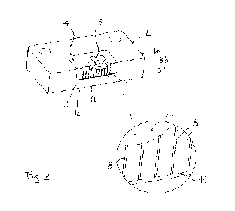
- figure 1 shows a perspective view of a half-mould of a mould for hot
forging,
comprising a mould holder and a die combined with the mould holder, in
accordance
with the present invention;
- figure 2 shows a perspective cross-sectional view of the half-mould of
figure 1,
with respective enlarged detail;
- figure 3 shows a perspective view of the aforesaid mould holder of the
half-
mould of figure 1;
- figure 4 shows a cross-sectional view of the mould holder of figure 3;
- figure 5 shows a perspective cross-sectional view of the die of the half-
mould
of figure 1, with respective enlarged detail, in accordance with an
implementation
variant of the invention;
- figure 6 shows a perspective cross-sectional view of the die of the half-
mould
of figure 1, with respective enlarged detail, in accordance with a further
implementation
variant of the invention.
Detailed description of the invention
With reference to figures 1-4, I generally denotes a half-mould of a mould for
hot forging, according to the present invention.
The half-mould 1 can be a so-called lower half-mould or a so-called upper half-
mould of the aforesaid mould which, therefore, may optionally comprise two
half-
moulds substantially similar as regards the structural and functional
characteristics in
accordance with the present invention.
In detail, the half-mould I comprises a mould holder 2 having a recess 3, and
a
die 4 provided with an impression 5, wherein the die 4 is combined with the
mould
holder 2 at the recess 3.
In practice, the impression 5 is also a recess that corresponds to the
negative of
- 1_0 -
CA 03192427 2023- 3- 10
WO 2022/090878
PCT/IB2021/059748
the geometry, or rather of part of the final geometry, of the semi-finished
product to be
achieved.
In accordance with the invention, the half-mould 1 is provided with a feeding
channel 6 for a lubricating-cooling liquid, substantially extending from an
outer wall 7
of the mould holder 2 to the recess 3 of the mould holder 2 and with a
plurality of
distribution channels for the lubricating-cooling liquid, each one denoted by
8, wherein
a quota of the aforesaid plurality of distribution channels consists of
distribution
channels extending from a wall 9 of the die 4 facing the recess 3, to the
impression 5.
In practice, a part of the distribution channels 8, i.e. the distribution
channels of
the aforesaid quota, have openings 8a facing the impression 5, while another
part of the
distribution channels 8, basically the distribution channels of a second quota
of the
aforesaid plurality of distribution channels, have openings 8b facing a wall
10 of the die
4 in which the impression 5 is arranged, at portions of the wall 10 outside
the
impression 5.
Moreover, in accordance with the invention, the feeding channel 6 and the
distribution channels 8 face a gap 11 formed between the mould holder 2 and
the die 4
at the recess 3.
Basically, in accordance with the above and according to the present
invention,
during the use of the half-mould 1, the lubricating-cooling liquid coming from
the
feeding channel 6 collects in the gap 11 from which it then reaches the
forging surface
of the half-mould 1, at the wall 10 of the die, through the distribution
channels 8 which
distribute the lubricating-cooling liquid substantially uniformly and
homogeneously on
the same forging surface, thanks to the surface tension of the lubricating-
cooling liquid.
In accordance with the invention, it should be added that the number of
distribution channels as well as the respective positions, the respective
dimensions, the
respective orientations and inclinations may vary, as required, also in a same
die, as well
as it is possible to provide for more than one feeding channel in the same
mould holder
and more gaps in the same half-mould. It should be noted that the homogeneity
of the
lubricating-cooling, i.e. a substantially homogeneous flow of the lubricating-
cooling
liquid on the surface of interest, is favoured by distribution channels with a
direction as
- 1_1 -
CA 03192427 2023- 3- 10
WO 2022/090878
PCT/IB2021/059748
perpendicular as possible to the surface to be lubricated.
In this regard, the distribution channels have a diameter preferably lower
than
about 0.4 mm, more preferably lower than about 0.3 mm, even more preferably
equal to
or lower than about 0.2 mm, the aforesaid die being preferably at least
partially
implemented with additive production techniques and preferably being
integrally
implemented with additive production techniques, without post-processing.
As is known, additive production or additive manufacturing or additive process
or layer manufacturing (Additive Manufacturing o AM) is an industrial process
used to
manufacture objects by starting from computerised 3D models, adding one layer
on top
of the other (3D printing), as opposed to the so-called traditional
subtractive production
methods which use milling machines or lathes and which start from a block of
material
from which chips or portions are mechanically removed.
The additive production allows to achieve complex geometries that cannot be
achieved with the aforesaid traditional methods, without generally increasing
the costs
to be incurred for the production of the final product which is the object of
the hot-
forging process
Again in this regard, in the example of the aforesaid figures, distribution
channels 8 are shown parallel to each other and perpendicular to the feeding
channel 6,
and therefore perpendicular to the gap 11.
It should be noted that in the example of the aforesaid figures, all the
distribution
channels 8, both those having the opening 8a facing the impression 5 and those
having
the opening 8b facing outside the impression 5, are parallel to each other and
substantially perpendicular to the feeding channel 6, therefore perpendicular
to the gap
11, the possibility of providing, in addition to or in place of, the aforesaid
distribution
channels parallel to each other being however not excluded, one or more
distribution
channels inclined with respect to the feeding channel, therefore inclined with
respect to
the gap, by an angle between about 5 and about 85 , and/or one or more non-
linear
distribution channels, as will better appear hereinafter.
It should also be added that, in order to make the gap 11, the die 4 is
provided, at
the aforesaid wall 9, with a step 12, the possibility of providing for such a
step also, or
- 12 -
CA 03192427 2023- 3- 10
WO 2022/090878
PCT/IB2021/059748
only, at the recess 3 of the mould holder 2 being however not excluded, as
well as it is
possible to provide for steps capable of making more than one gap of the
aforesaid type
and as well as it is possible to provide for other means capable of making at
least one
gap of the aforesaid type, e.g. spacers.
In the example of the aforesaid figures, the half-mould 1 is also shown with
holes 13 adapted to be engaged by the columns of a press provided for carrying
out hot
forging with the present mould.
Finally, it should be added that the mould holder 2 preferably consists of a
forged steel block which can be used to implement several pieces, i.e. several
semi-
finished products, and which can be provided with a plurality of inner
channels for
cooling circuits, of a known type, in the examples of the figures not
depicted.
Figure 5 shows the die of the half-mould of figure 1 in accordance with an
implementation variant of the invention, in which parts structurally and
functionally
corresponding to those of the die 4 described above retain the same reference
numerals
of figures 1-4.
In detail, the example of figure 5 shows a die 104 which is entirely similar
to the
die 4, the description of which is set forth above, except for the fact that
it comprises
distribution channels 108 for the lubricating-cooling liquid, which are
inclined, not
parallel to each other and converging toward an impression 105, as mentioned
above.
In the example of figure 5, a step 12 of the die 104 is also depicted, which
is
adapted to form a gap with the recess of the respective mould holder which, in
this case,
may be a mould holder entirely similar to the mould holder 2 referred above,
the
description of which is provided above.
In the example of figure 5, moreover, the die 104 is provided only with
distribution channels 108 which have the respective openings 108a facing the
impression 105.
Figure 6 shows the die of the half-mould of figure 1 in accordance with a
further
implementation variant of the invention, in which parts structurally and
functionally
corresponding to those of the die 4 described above, retain the same reference
numerals
of figures 1-4.
- 13 -
CA 03192427 2023- 3- 10
WO 2022/090878
PCT/IB2021/059748
In detail, the example of figure 6 shows a die 204 entirely similar to the die
4,
the description of which is provided above, except for the fact that it
comprises non-
linear distribution channels 208 for the lubricating-cooling liquid, as
mentioned above.
In detail, the distribution channels 208 comprise a first length 208a
substantially
perpendicular to a gap which the die 204 forms with a recess of the respective
mould
holder, in the example of figure 6 not shown, and a second length 208b
substantially
perpendicular to an impression 205 provided in the die 204.
In the example of figure 6, a step 12 of the die 204 is also depicted, which
is
adapted to form the aforesaid gap with the recess of the mould holder which,
in this
case, may be a mould holder entirely similar to the mould holder 2 referred
above, the
description of which is provided above.
Moreover, in the example of figure 6, the die 204 is provided only with
distribution channels 208 which have the respective opening 108a facing the
impression
205.
A die in accordance with the example of figure 6 makes the most of the
potentials of additive production, since it allows to direct the flow of the
lubricating-
cooling liquid to a direction substantially perpendicular both to its inlet in
the
distribution channels and to its outlet from the distribution channels.
In accordance with the foregoing, a hot forging process according to the
present
invention is now described, which comprises the steps of:
- a) providing a mould for hot forging of the type described above, i.e.
comprising a first half-mould and a second half-mould in which at least one
half-mould
1 between the first half-mould and the second half-mould comprises a mould
holder 2
having a recess 3, and a die 4, 104, 204 provided with an impression 5, 105,
205, in
which the die 4, 104, 204 is combined with the mould holder 2 at the recess 3,
wherein
the half-mould 1 is provided with a feeding channel 6 for a lubricating-
cooling liquid,
which is substantially extending from an outer wall 7 of the mould holder 2 to
the recess
3 of the mould holder 2, and with a plurality of distribution channels 8, 108,
208 for the
lubricating-cooling liquid, wherein at least one quota of the distribution
channels 8, 108,
208 comprises distribution channels extending from a wall 9 of the die 4, 104,
204
- 14 -
CA 03192427 2023- 3- 10
WO 2022/090878
PCT/IB2021/059748
facing the recess 3, to the impression 5, 105, 205, wherein the feeding
channel 6 and the
distribution channels 8, 108, 208 face a gap 11 formed between the mould
holder 2 and
the die 4, 104, 204 at the recess 3 of the mould holder 2;
- b) feeding, under pressure, the lubricating-cooling liquid into the
feeding
channel 6,
- c) feeding a preheated billet into the first half-mould or the second
half-mould
of the mould;
- d) closing the mould by applying a pre-set pressure to the first half-
mould
and/or to the second half-mould;
- e) cooling the mould;
- f) opening the mould;
- g) ejecting a forged semi-finished product achieved from the aforesaid
billet.
Advantageously, in accordance with the invention, the aforesaid step b) in
which
the lubricating-cooling liquid is fed into the feeding channel 6, allows to
lubricate, in a
substantially homogeneous manner, the forging surface of the half-mould 1,
considering
also that, during the present process, the aforesaid distribution channels are
preferably
constantly crossed by the lubricating-cooling liquid, i.e. they are preferably
substantially
always full of lubricating-cooling liquid during the process.
This way, having defined, during the die designing step, the number of
channels
for distributing the lubricating-cooling liquid, the position of the
distribution channels,
their diameter, their orientation and their inclination, it is possible to
have the pressure
applied to the lubricating-cooling liquid as the only process parameter.
Advantageously, moreover, if necessary, the lubricating-cooling liquid may
also
be used to eject the semi-finished product achieved by forging. In this
regard, in the
present process, the aforesaid step g) may be carried out by increasing the
pressure of
the lubricating-cooling liquid. In fact, due to the presence of the semi-
finished product
inside the mould which blocks the distribution channels of the die, the
lubricating-
cooling liquid may be compressed inside the same distribution channels until
the semi-
finished product is detached, all controlled by an automated control unit.
Furthermore, the use of the lubricating-cooling liquid to eject the semi-
finished
- 15 -
CA 03192427 2023- 3- 10
WO 2022/090878
PCT/IB2021/059748
product advantageously allows to make moulds without the classic ejectors,
thus
reducing the complexity of the mould holders.
As regards the lubricating-cooling liquid, it should be stated that it is
possible to
use any lubricating-cooling liquid of known type.
The advantages of the present invention, which are evident in the above
description, can be summarised by pointing out that a mould for hot forging
has been
provided in which the traditional spray lubrication system is replaced by a
diffusion
system from the inside of the mould, or rather of the half-mould, of the
lubricating-
cooling liquid, which substantially entails:
for the lubrication, only using the lubricating-cooling liquid necessary to
form a
thin film on the forging surface of a half-mould, without waste;
reducing the lubricating-cooling liquid dispersed in the mould and in the
entire
equipment comprising the mould, resulting in less frequent cleaning and
maintenance
operations, thus lengthening the operating useful life of the mould and the
respective
equipment;
dispersing the lubricating-cooling liquid in the surrounding environment is
avoided and, therefore, the need to resort to constantly active suction
systems is
avoided, resulting in reduced energy consumption;
during the die designing step, the distribution of the lubricating-cooling
liquid
reaching the forging surface can be effectively envisaged, by defining the
number,
position, orientation, inclination and diameter of the channels for
distributing the
lubricating-cooling liquid, therefore being able to control effectively,
during the process,
the distribution of the lubricating-cooling liquid reaching the forging
surface;
during the process, the lubrication step becomes simpler to manage, since the
only parameter to be managed consists of the pressure applied to the
lubricating-cooling
liquid as time varies, a pressure which can therefore be advantageously
controlled by a
PLC system.
In the embodiments depicted and described, in order to satisfy contingent and
specific requirements, a person skilled in the art may make numerous
variations and
modifications to the present invention, all of which are within the scope of
protection of
- 16 -
CA 03192427 2023- 3- 10
WO 2022/090878
PCT/IB2021/059748
the invention as defined by the following claims
- 17 -
CA 03192427 2023- 3- 10