Note: Descriptions are shown in the official language in which they were submitted.
CA 03192620 2023-02-22
WO 2022/046623
PCT/US2021/047131
TRIMETAL SUPPORTED CATALYST
TECHNICAL FIELD
[0001] The present disclosure relates to a novel trimetal supported catalyst
which is useful in
hydrocracking systems. Processes for preparing and using the trimetal
supported catalyst are
also disclosed.
BACKGROUND
[0002] Hydrocracking of hydrocarbon feedstocks is often used to convert lower
value
hydrocarbon fractions into higher value products, such as conversion of vacuum
gas oil (VGO)
feedstocks to various fuels and lubricants. Hydrocracking refers to a process
in which
hydrogenation and dehydrogenation accompanies the cracking/fragmentation of
hydrocarbons,
e.g., converting heavier hydrocarbons into lighter hydrocarbons, or converting
aromatics and/or
cycloparaffins (naphthenes) into non-cyclic branched paraffins. Typical
hydrocracking
reaction schemes can include an initial hydrotreatment step, a hydrocracking
step, and a post-
hydrocracking step. After these steps, the effluent can be fractionated to
separate out a desired
diesel fuel and/or lubricating base oil.
[0003] Conventionally supported hydrocracking catalysts are prepared with Ni
and W metals
to provide hydrogenation functions in the C-C cracking process. Lately, Ni, Mo
and W metals
have been employed in the self-supported hydroprocessing catalyst through co-
precipitation.
See, for example, U.S. Patent No. 9,919,987.
[0004] There is a demand, however, for new catalysts which can provide other
improved
functions such as HDN and HDS activity, as well as a dewaxing function.
SUMMARY
[0005] Provided is a novel catalyst comprised of an alumina, silica-alumina,
and a zeolite
containing base impregnated with Ni, Mo, and W. In one embodiment, the
trimetallic catalyst
is layered with a conventional pretreat hydrocracking catalyst to provide a
catalyst combination
useful in pretreating a feed to a hydrocracker.
[0006] In one embodiment, the catalyst comprises from 2 to 10 wt. % Ni
precursor; from 3-15
wt. % Mo precursor; and from 10 to 50 wt. % W precursor, based on the bulk dry
weight of the
catalyst. In another embodiment, the catalyst base comprises 0.1 to 40 wt. %
alumina, 20 to 80
wt. % silica alumina, e.g., amorphous silica alumina (ASA), and 0.5 to 60 wt.
% zeolite, e.g.,
USY zeolite, based on the dry wright of the base.
1
CA 03192620 2023-02-22
WO 2022/046623
PCT/US2021/047131
[0007] In another embodiment, there is provided a process comprising preparing
a mixture of a
molybdenum precursor and H3PO4; preparing an aqueous solution comprising a
tungsten
precursor and a nickel precursor; combining the solutions to form a
trimetallic solution; and
impregnating the base with the trimetallic solution.
[0008] In one embodiment, there is provided a hydrocracking process. The
process comprises
subjecting a hydrocarbon feed to a pretreatment reaction over a catalyst
combination
comprising the present catalyst layered with a hydrocracking pretreat
catalyst. The resulting
effluent is then passed from the pretreatment reaction zone to a hydrocracking
zone. In the
pretreatment reaction zone, the catalyst combination is layered with the
hydrocracking pretreat
catalyst the top layer, and the present trimetallic catalyst as the bottom
layer.
[0009] Among other factors, the present catalyst can be used in hydrocracking
systems to offer
excellent pretreatment of the hydrocracking feed. Combining the present
supported trimetallic
catalyst with a conventional hydrocracking pretreat catalyst, or vacuum gas
oil hydrotreating
catalyst, as a layered combination, with the hydrocracking pretreat catalyst
the top layer, has
been found to offer improved HDN and HDS activity. Improved dewaxing of the
feed has also
been observed, allowing any subsequent dewaxing process in the system to be
run at less harsh
conditions.
BRIEF DESCRIPTION OF THE DRAWINGS
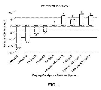
[0010] FIG. 1 graphically compares the HDN activity in hydrotreating VG01 feed
over
varying catalysts.
[0011] FIG. 2 graphically compares the HDS activity in hydrotreating VG01 feed
over varying
catalysts.
[0012] FIG. 3 graphically compares wax content of a waxy base oil prepared
using two lube
hydrocracking catalyst systems.
DETAILED DESCRIPTION
[0013] The present trimetallic supported catalyst is prepared from sources of
nickel,
molybdenum and tungsten in their compound or ionic form ("metal precursors").
Any suitable
nickel, molybdenum or tungsten metal precursor can be used to prepare metal
precursor
solutions, e.g., any oxide or salt.
[0014] Examples of nickel precursors include oxides or sulfides of nickel,
organic compounds
of nickel (e.g., nickel naphthenate, nickelocene), nickel carbonate, nickel
chloride, nickel
hydroxide, nickel nitrate and nickel sulfate.
[0015] Examples of molybdenum precursors include oxides or sulfides of
molybdenum,
organic compounds of molybdenum (e.g., molybdenum naphthenate), sulfur-
containing organic
2
CA 03192620 2023-02-22
WO 2022/046623
PCT/US2021/047131
compounds of molybdenum (e.g., molybdenum dithiocarbamates, molybdenum
dithiophosphates), molybdic acid, alkali metal or ammonium molybdates (e.g.,
sodium
molybdate, ammonium molybdate, ammonium molybdate tetrahydrate, ammonium
heptamolybdate, ammonium tetrathiomolybdate), Mo¨P heteropolyanion compounds
(e.g.,
phosphomolybdic acid, sodium phosphomolybdate, ammonium phosphomolybdate),
Mo¨Si
heteropolyanion compounds (e.g., 12-molybdosilicic acid), and molybdenum
chlorides.
[0016] Examples of tungsten precursors include oxides or sulfides of tungsten,
organic
compounds of tungsten (e.g., cyclopentadienyl tungsten dihydride), tungstic
acid, alkali metal
or ammonium tungstates (e.g., sodium tungstate, sodium polytungstate, ammonium
tungstate,
ammonium metatungstate, ammonium tetrathiotungstate), W¨P heteropolyanion
compounds
(e.g., 12-tungstophosphoric acid), and tungsten chlorides.
[0017] The catalyst precursor may be prepared in the presence of an organic
complexing or
modifying agent ("L"). Preferably, the organic complexing agent is a metal
binding group or
chelating agent. Preferably, the organic complexing agent is a bidentate
ligand. In one
embodiment, the organic complexing agent is suitable for forming metal-ligand
complexes in
solution.
[0018] Organic acids are a preferred class of organic complexing agent. In one
embodiment,
the organic complexing agent is an organic acid that contains a carboxylic
acid functional
group and at least one additional functional group selected from carboxylic
acid, hydroxamic
acid, hydroxo, keto, amine, amide, imine, or thiol. Examples of organic
complexing agents
suitable for use herein include glyoxylic acid, glycolic acid, diglycolic
acid, thioglycolic acid,
pyruvic acid, oxalic acid, malonic acid, maleic acid, succinic acid, lactic
acid, malic acid,
tartaric acid, citric acid, glycine, oxamic acid, glyoxylic acid 2-oxime,
ethylenediaminetetraacetic acid, nitrilotriacetic acid, N-methylaminodiacetic
acid and
iminodiacetic acid. A preferred organic acid is citric acid.
[0019] The amount of organic complexing agent used in the mixed solution
should also be
enough to form metal-organic complexes in the solution under reaction
conditions. In an
embodiment where the complexing agent is an organic acid, the ratio of
carboxylic acid groups
of the organic acids to metals can be at least 0.33, e.g., at least 0.5, at
least about 1 (meaning
that about the same number of carboxylic acid groups and metal atoms are
present), at least 2,
or at least 3. In another embodiment, the ratio of carboxylic acid groups to
metals can be 12 or
less (e.g., 10 or less, or 8 or less).
[0020] In another embodiment, the molar ratio used in the mixing solution of
organic
complexing agent to metals is 6:1 or less (e.g., 5.5:1 or less, 5:1 or less,
or 4.5:1 or less). In yet
3
CA 03192620 2023-02-22
WO 2022/046623
PCT/US2021/047131
another embodiment, the molar ratio used in the mixing solution of organic
complexing agent
to metals is 0.5:1 or more (e.g., 1:1 or more, or 1.5:1 or more, 2:1 or more,
2.5:1 or more, 3:1 or
more, or 3.5:1 or more).
10021] The amount of metal precursors and complexing or modifying agent (when
employed) in the impregnation solution should be selected to achieve preferred
ratios of
metal to modifying agent in the catalyst precursor after drying.
[0022] The base of the catalyst which is impregnated with the three metals,
can comprise from
about 0.1 to about 40 wt. % alumina base, based on the dry weight of the base,
or in another
embodiment from about 10 to about 30 wt. % alumina. About 25 wt. % alumina can
be used in
another embodiment. The base of the catalyst can also comprise from about 20
to about 80 wt.
% of a silica alumina, based on the dry weight of the base, or in another
embodiment from
about 30 to about 80 wt. % silica alumina. Any suitable silica alumina can be
used. In one
embodiment the silica alumina is amorphous silica alumina (ASA). The zeolite
can generally
comprise from 0.5 to about 60 wt. % of the base, based on the dry weight of
the base. In
another embodiment, the zeolite can comprise from about 1 to about 50 wt. % of
the base.
[0023] The alumina can be any alumina known for use in a catalyst base. For
example, the
alumina can be y-alumina, malumina, 0-alumina, 6-alumina, x-alumina, or a
mixture thereof
[0024] The silica alumina of the catalyst support is preferably in one
embodiment an
amorphous silica-alumina material in which the mean mesopore diameter is
generally between
70A and 130A.
[0025] In one embodiment, the amorphous silica-alumina material contains SiO2
in an amount
of 10 to 70 wt. % of the bulk dry weight of the carrier as determined by ICP
elemental analysis,
a BET surface area of between 450 and 550 m2/g and a total pore volume of
between 0.75 and
1.35 mL/g.
[0026] In another embodiment, the catalyst support comprises an amorphous
silica-alumina
material containing SiO2 in an amount of 10 to 70 wt. % of the bulk dry weight
of the carrier as
determined by ICP elemental analysis, a BET surface area of between 450 and
550 m2/g, a total
pore volume of between 0.75 and 1.35 mL/g, and a mean mesopore diameter is
between 70 A
and 130 A.
[0027] In another embodiment, the catalyst support is a highly homogeneous
amorphous silica-
alumina material having a surface to bulk silica to alumina ratio (S/B ratio)
of 0.7 to 1.3, and a
crystalline alumina phase present in an amount no more than about 10 wt. %.
(Si/A1 atomic ratio of the surface area measured by XPS)
S/B Ratio =
(Si/A1 atomic ratio of the bulk measured by elemental analysis)
4
CA 03192620 2023-02-22
WO 2022/046623
PCT/US2021/047131
[0028] To determine the S/B ratio, the Si/A1 atomic ratio of the silica-
alumina surface is
measured using x-ray photoelectron spectroscopy (XPS). XPS is also known as
electron
spectroscopy for chemical analysis (ESCA). Since the penetration depth of XPS
is less than 50
A, the Si/A1 atomic ratio measured by XPS is for the surface chemical
composition.
[0029] Use of XPS for silica-alumina characterization was published by W.
Daneiell et al. in
Applied Catalysis A, 196, 247-260, 2000. The XPS technique is, therefore,
effective in
measuring the chemical composition of the outer layer of catalytic particle
surface. Other
surface measurement techniques, such as Auger electron spectroscopy (AES) and
Secondary-
ion mass spectroscopy (SIMS), could also be used for measurement of the
surface composition.
[0030] Separately, the bulk Si/A1 ratio of the composition is determined from
ICP elemental
analysis. Then, by comparing the surface Si/A1 ratio to the bulk Si/A1 ratio,
the S/B ratio and
the homogeneity of silica-alumina are determined. How the SB ratio defines the
homogeneity
of a particle is explained as follows. An S/B ratio of 1.0 means the material
is completely
homogeneous throughout the particles. An S/B ratio of less than 1.0 means the
particle surface
is enriched with aluminum (or depleted with silicon), and aluminum is
predominantly located
on the external surface of the particles. The S/B ratio of more than 1.0 means
the particle
surface is enriched with silicon (or depleted with aluminum), and aluminum is
predominantly
located on the internal area of the particles.
[0031] The zeolite can be any suitable zeolite used in hydrocracking
catalysts. For example,
the zeolite can be a USY zeolite, a beta zeolite, ZSM-12, ZSM-22, ZSM-48, SSZ-
33, SSZ-41,
SSZ-42, SSZ-53, SSZ-60, SSZ-65, SSZ-70, SSZ-82, SSZ-91, SSZ-109, a mordenite
zeolite,
and mixtures thereof A USY zeolite is preferred in one embodiment.
[0032] "Zeolite USY" refers to ultra-stabilized Y zeolite. Y zeolites are
synthetic faujasite
(FAU) zeolites having a SAR of 3 or higher. Y zeolite can be ultra-stabilized
by one or more
of hydrothermal stabilization, dealumination, and isomorphous substitution.
Zeolite USY can
be any FAU-type zeolite with a higher framework silicon content than a
starting (as-
synthesized) Na-Y zeolite precursor. Such suitable Y zeolites are commercially
available from,
e.g., Zeolyst, Tosoh and JGC.
[0033] The base is impregnated with the three metals to produce the present
supported
trimetallic catalyst. In one embodiment, the process for preparing the
catalyst comprises
preparing two solutions. One solution comprises a mixture of a molybdenum (Mo)
precursor
and H3PO4. The presence of the H3PO4 allows for a clear solution. The other
solution is an
aqueous solution comprising a tungsten (W) precursor and a nickel (Ni)
precursor. The two
solutions are combined to form a trimetallic solution. It has been found that
the presence of the
CA 03192620 2023-02-22
WO 2022/046623
PCT/US2021/047131
H3PO4 aids in the resulting trimetallic solution being clear. The base is then
impregnated with
the trimetallic solution using conventional impregnation techniques.
[0034] In one embodiment, the molybdenum precursor is ammonium molybdate
tetrahydrate.
In one embodiment, the tungsten precursor is ammonium metatungstate. In one
embodiment,
the nickel precursor is nickel carbonate.
[0035] In another embodiment, an organic acid is also added to the aqueous
solution
comprising the tungsten and nickel precursors as a complexing or modifying
agent. Citric acid
is one such organic acid often used.
[0036] The loading of the solutions is such that the ultimate catalyst
comprises from 2 to 10 wt.
%Ni precursor; from 3-15 wt. % Mo precursor; and 10 to 50 wt. % W precursor,
based on the
bulk dry weight of the catalyst. The molar ratio of W to Mo in the catalyst
generally ranges
from about 1.2 to about 4Ø If the ultimate catalyst is calcined to produce
metal oxides, the
loading is such that the final catalyst comprises from 2-10 wt. % NiO, 3-15
wt. % Mo03, and
15-40 wt. % W03 based on the bulk dry weight of the catalyst. With oxides, the
weight ratio of
W03 to Mo03 generally ranges from about 2.0 to about 6.4. Generally, when an
organic acid is
used in the impregnation, calcination to oxides is not employed.
[00371 More specifically, the base is prepared with its components and. often
extruded. The
extrudate is exposed to the impregnation solution until incipient wetness is
achieved,
typically for a period of between 0.5 and 100 hours (more typically between I
and 5 hours) at
room temperature to 212 F (1000 C) while tumbling the extrudates, following
by aging for
from 0. Ito 10 hours, typically from about 0.5 to about 5 hours.
100381 The drying step is conducted at a temperature sufficient to remove the
impregnation
solution solvent, but below the decomposition temperature of the modifying
agent In
another embodiment, the dried impregnated extrudate is then calcined at a
temperature, above
the decomposition temperature of the modifying agent, if used, typically from
about 500 F
(260 C) to 1100' F (5900 C), for an effective amount of time. The present
invention
contemplates that when the impregnated extrudate is to be calcined, it will
undergo drying
during the period where the temperature is being elevated or ramped to the
intended
calcination temperature. This effective amount of time will range from about
0.5 to about 24
hours, typically from about I to about 5 hours. The calcin.a.tion can be
carried out in the
presence of a flowing oxygen-containing gas such as air, a flowing inert gas
such as nitrogen,
or a combination of oxygen-containing and inert gases.
6
CA 03192620 2023-02-22
WO 2022/046623
PCT/US2021/047131
100391 In one embodiment, the impregnated extrudate is calcined at a
temperature which
does not convert the metals to metal oxides. Yet in another embodiment, the
impregnated
extrudate can be calcined at a temperature sufficient to convert the metals to
metal oxides.
1004O1 The dried and calcined catalysts of the present invention can be
sulfided to form an
active catalyst. Sulfiding of the catalyst precursor to form the catalyst can
be performed prior
to introduction of the catalyst into a reactor (thus ex-situ presulfiding), or
can be carried out
in the reactor (in-situ sulfidinct).
1004111 Suitable sulfiding agents include elemental sulfur, ammonium sulfide,
ammonium
polysulfi de ([(NI-L02Sx), ammonium thiosulfate ((NIL )2S203), sodium
thiosuffate (Na2S203),
thiourea CSN2H4, carbon disulfide, dimethyl disulfide (DMDS), dimethyl sulfide
(DM'S),
di butyl polysulfide (DBPS), mercaptanes, tertialy butyl poly sulfide (PSTB),
terharynonyl
polysulfide (PSTN), aqueous ammonium sulfide.
100421 Generally, the sulfiding agent is present in an amount in excess of the
stoichiometric
amount required to form the sulfided catalyst. In another embodiment, the
amount of
sulfiding agent represents a sulphur to metal mole ratio of at least 3 to 1 to
produce a sulfided
catalyst.
[WW1 The catalyst is converted into an active sulfided. catalyst upon contact
with the
sulfiding agent at a temperature of 150" F to 900 F (66 C to 482 C), from
10 minutes to 15
days, and under a 11r-containing gas pressure of 101 kPa to 25,000 kPa. If the
sulfidation
temperature is below the boiling point of the sulfiding agent, the process is
generally carried
out at atmospheric pressure. Above the boiling temperature of the sulfiding
agent/optional
components, the reaction is generally carried out at an increased pressure. As
used herein,
completion of the sulfidation process means that at least 95% of
stoichiometfic sulfur
quantity necessary to convert the metals into for example, C09S8, M082, WS2,
Ni3S2, etc., has
been consumed.
100441 In one embodiment, the sulfi ding can be carried out to completion in
the gaseous
phase with hydrogen and a sulfur-containing compound which is decomposable
into H2S.
Examples include mercaptanes, CS2, thiophenes, DMS, DMDS and suitable S-
containing
refinery outlet gasses. The gaseous mixture ofl-I2 and sulfur containing
compound can be the
same or different in the steps. The sulfidation in the gaseous phase can be
done in any
suitable manner, including a fixed bed process and a moving bed process (in
which the
catalyst moves relative to the reactor, e.g.., ebullated process and rotary
furnace).
100451 The contacting between the catalyst precursor with hydrogen and a
sulfur-containing
compound can be done in one step at a temperature of 68 F to 700 F (20 C to
371 C) at a
7
CA 03192620 2023-02-22
WO 2022/046623
PCT/US2021/047131
pressure of 101 kPa to 25,000 kPa Ibr a period of I to 100 hrs. Typically,
suifidation is
carried ota over a period of time with the temperature being increased or
ramped in
increments and held over a period of time until completion.
100461 In another embodiment sulfidation can be in the gaseous phase. The
sulfidation is
done in two or more steps, with the first step being at a lower temperature
than the
subsequent step(s).
100471 In one embodiment, the sulfidation is carried out in the liquid phase.
At first, the
catalyst precursor is brought in contact with an organic liquid in an amount
in the range of
20% to 500% of the catalyst total pore volume. The contacting with the organic
liquid can be
at a temperature ranging from ambient to 248 F (120 C). After the
incorporation of an
organic liquid, the catalyst precursor is brought into contact with hydrogen
and a sulfur-,
containing compound.
100481 In one embodiment, the organic liquid has a boiling range of 200 F to
1200 F (93 C
to 649 C). Exemplary organic liquids include petroleum ft-actions such as
heavy oils,
lubricating oil fractions like mineral lithe oil, atmospheric gas oils, vacuum
gas oils, straight
run gas oils, white spirit, middle distillates like diesel, jet fuel and
heating oil, naphtha, and
gasoline. In one embodiment, the organic liquid contains less than 10 wt. %
sulfur, and
preferably less than 5 wt. %.
100491 The present catalyst is useful in hydrocracking systems. It can be used
as a
hydrocracking catalyst in a hydrocracking zone. Particular use has been
discovered when the
present trimetal supported catalyst is combined with a conventional
hydrocracking pretreat
catalyst as a layered combination. In particular, the comentional pretreat
catalyst is the top
layer and meets the hydrocracking feed first. This layered combination is
advantageously
used in the pretreating or b.:,,idrotre.ating zone of a hydrocracking reaction
stage. The top layer
catalyst can generally comprise from 60-85 vol. % of the layered combination,
and the
present catalyst from 15-40 vol. %. Preferred is an 80 vol. % to 20 vol. %
combination.
100501 The COTIVeditional pretreat catalyst of the top layer can be any
conventional catalyst
used in the pretreat or hydrotreating zone of a hydrocracking system to effect
hydrodenitrogenation and/or by drodesulfurization Such conventional pretreat
catalysts do
not comprise the trimetallic combination of the present catalyst. Examples of
such pretreat or
hydrotreating catalysts include ICR 513,1CR 514, and1CR 1000 series available
from ART;
ExxonMobil catalysts available under the trademarks Celestiat, Nebula , and
MIDWO; and
the Al hermarle catalysts KF 880 and KF 870. Combining/layering such a
catalyst with the
present catalyst has been found to be quite advantag,es.
8
CA 03192620 2023-02-22
WO 2022/046623
PCT/US2021/047131
100511 The present combination catalyst has been found to have particular
application in
hydrocracking processes as the pretreatment or hydrotreating zone. Once the
feed passes the
layered combination, the resulting effluent is passed onto a hydrocracking
zone. The
pretreatment zone is operated under conventional conditions of temperature and
pressure for
a pretreatment or hydrotreating zone. Particular application has also been
found for
hydrocracking feeds designed for producing a diesel fuel or a lubricating base
oil.
EXAMPLES
[0052] The following illustrative examples are intended to be non-limiting.
Example 1: Preparation of alumina catalyst Support A
[0053] Catalyst Support A was prepared according to U52014/0367311 Al. An
alumina
containing slurry was prepared as follows: to a tank was added 13630 L of city
water. The
temperature was brought to 120 F (49 C) with heating. An aluminum sulfate
stream and a
sodium aluminate stream are added continuously to the tank under agitation.
The aluminum
sulfate stream consists of an aqueous solution of aluminum sulfate (containing
8.3 wt.% Al2O3,
76 L/min) inline diluted with water (79.9 L/min), while the sodium aluminate
stream was
composed of an aqueous solution of sodium aluminate (containing 25.5 wt.%
A1203) inline
diluted with water (134 L/min). The addition speed of the sodium aluminate
solution in the
sodium aluminate stream was controlled by the pH of the alumina slurry. The pH
was
controlled at 9.0 and temperature at 120 F (49 C). The temperature control
was achieved
through adjusting the temperature of dilution water for both streams. After
2,082 L of the
aqueous solution of sodium aluminate was added to the tank, both aluminum
sulfate and
sodium aluminate streams are stopped. The temperature of the resulting slurry
was increased to
127 F (53 C) with steam injection for 35 min. Both aluminum sulfate and
sodium aluminate
streams are resumed while the steam injection was kept on. During this step,
the pH of the
slurry was kept at 9.0, while the temperature was allowed to rise freely. The
precipitation was
stopped once 4542 L of the aqueous aluminum sulfate solution was added. The
final
temperature of the slurry reaches 149 F (65 C). After the precipitation was
stopped, the pH
was raised with addition of the same aqueous sodium aluminate to 9.3. The
alumina slurry was
then filtered and washed to remove Na + and 5042-. This slurry is referred to
as slurry A.
[0054] After about half of slurry A was pumped to another tank, it was
heated to 140-151
F (60-66 C) with steam injection and maintained at this temperature. MS-25
silica-alumina
(63.5 kg, from W.R. Grace) was added to the tank. The amount of MS-25 was
controlled so
that the final support contained 3% Sift. Acetic acid (113 kg, 29.2%) was
subsequently added
9
CA 03192620 2023-02-22
WO 2022/046623
PCT/US2021/047131
to the slurry before it was agitated for 30 min. After the agitation, ammonia
(60.8 kg, 6.06%)
was added before the slurry was filtered to give a cake. The obtained cake was
dried at about
550 F (288 C) to give an alumina powder containing about 60% moisture. The
powder was
next transferred to a mixer and treated with 0.5% HNO3 and 10% of recycle
catalyst/support
fines. The mixture was kept mixing until an extrudable mixture was formed. The
mixture was
then extruded in 1/16" asymmetric quadrilobe shape, dried, and calcined at
1350 F (732 C) to
give a catalyst Support A.
Example 2: Preparation of alumina catalyst Support B
[0055] Alumina Support B was prepared in the same way as alumina Support A.
The
difference is the drying step changed from spray dry to holoflite dry at
comparable temperature
to produce an alumina powder containing about 60% moisture. This drying
process produced
alumina powder with a slightly higher pore volume and larger pore size. The
powder was then
transferred to a mixer and treated with 0.5% HNO3 and 10% of recycle
catalyst/support fines.
The mixture was kept mixing until an extrudable mixture was formed. The
mixture was then
extruded in 1/16" asymmetric quadrilobe shape, dried, and calcined at 1350 F
(732 C) to give
the catalyst Support B.
Example 3: Preparation of zeolite-containing hydrocracking catalyst Support C
[0056] A hydrocracking catalyst Support C was prepared according to method
described in
US Pat. No. 9,187,702 B2. Silica-alumina powder (obtained from Sasol, PIDC,
JGC) of 67 g
(dry weight, weighed after drying the sample at 1099 F (593 C), pseudo
boehmite alumina
powder (obtained from Sasol) of 25 g (dry weight) and 8 g of zeolite Y (from
Zeolyst, JGC,
Tosoh) were mixed well. A 1M HNO3 acid aqueous solution (1 wt. % of dry
catalyst support)
was added to the mix powder to form an extrudable paste. The paste was
extruded in 1/16"
asymmetric quadrilobe shape and dried at 248 F (120 C) overnight. The dried
extrudates
were calcined at 1099 F (593 C) for 1 h with purging excess dry air and
cooled down to room
temperature to give the Support C.
Example 4: Preparation of zeolite-containing hydrocracking catalyst Support D
[0057] A hydrocracking catalyst Support D was prepared in the same way as
catalyst
Support C except for using a high pore-volume silica-alumina powder of 67 g
(dry weight,
weighed after drying the sample at 1099 F (593 C), pseudo boehmite alumina
powder
(obtained from Sasol) of 25 g (dry weight) and 8 g of zeolite Y (from Zeolyst,
JGC, Tosoh)
CA 03192620 2023-02-22
WO 2022/046623
PCT/US2021/047131
were mixed well. A 1M HNO3 acid aqueous solution (1 wt. % of dry catalyst
support) was
added to the mix powder to form an extrudable paste. The paste was extruded in
1/16"
asymmetric quadrilobe shape and dried at 248 F (120 C) overnight. The dried
extrudates
were calcined at 1099 F (593 C) for 1 h with purging excess dry air and
cooled down to room
temperature to give the catalyst Support D.
Example 5: Preparation of hydrocracking pretreat Catalyst A (NixMoyP)
[0058] The Catalyst A was impregnated with an aqueous Ni¨Mo¨P metal
solution on
catalyst Support A. The detailed preparation is described in W02015/164464 Al.
116.7 g of
citric acid was added to 400 mL of water in a round bottom flask equipped with
stirrer. 194.75
g of nickel carbonate (49% Ni) was added to the above solution. 189.34 g of
phosphoric acid
(85%) was then added slowly to the solution and the solution was heated to 150
F (66 C).
Then, 475.95 g of molybdenum trioxide was added to the solution. The solution
was heated to
about 190 F to 210 F and held at that temperature range for at least 1.5 h
until the solution
became clear. Once the solution became clear, it was cooled to below 120 F
(49 C) and an
additional 272.8 g of citric acid was added and the mixture was stirred until
the solution
became clear. The solution was diluted with deionized water to 1000 mL. The
final Mo03
concentration was 0.4750 g/mL of solution. Analysis of the resulting NixMoyPz
solution
showed the following composition (metals expressed as the oxides):
concentration in wt. % on
a dry basis: NiO, 6.0; P205 6.5; Mo03, 25Ø The solution contained the
following component
ratio: 0.4 citric acid/(NiO + Mo03) (mol/mol).
[0059] Catalyst A was prepared by impregnating the catalyst Support A using
the
NixMoyPz solution. The support was impregnated by the incipient wetness
method, e.g. the
total volume of the metal solution matches the 103% water pore volume of the
support
extrudates. Then the wet extrudates were heated in air at 320 F (160 C) for
ten minutes,
11
CA 03192620 2023-02-22
WO 2022/046623
PCT/US2021/047131
ramped to 680 F (360 C) over 40 minutes, and held at 680 F (360 C) for 10
minutes to
produce Catalyst A.
Example 6: Preparation of hydrocracking pretreat Catalyst B (NixMoyP)
[0060] The Catalyst B was prepared with the same metal solution, metal
loading and
calcination conditions as the Catalyst A. The only difference is the use of
catalyst Support B.
Example 7: Preparation of hydrocracking Catalyst C (NiW y with citric acid)
[0061] NiW hydrocracking Catalyst C was prepared with catalyst Support C.
Impregnation
of Ni and W was done using an aqueous solution containing ammonium
metatungstate and
nickel carbonate to the target metal loadings of 6.0 wt. % NiO and 22.0 wt. %
W03 in the
finished catalyst. Citric acid at the amount of 12.2 wt. % of finished dry
catalyst was added to
the NiW solution. The solution was heated to above 122 F (50 C) to ensure a
completed
dissolved (clear) solution. The total volume of the metal solution matches the
103% water pore
volume of the base extrudates (incipient wetness method). The metal solution
was added to the
support extrudates gradually while tumbling the extrudates. When the solution
addition was
completed, the soaked extrudates are aged for 2 h. Then the wet extrudates
were heated in air
at 320 F (160 C) for ten minutes, ramped to 680 F (360 C) over 40 minutes,
and held at 680
F (360 C) for 10 minutes to produce the Catalyst C.
Example 8: Preparation of hydrocracking Catalyst D (NixWyMozP with citric
acid)
[0062] Trimetallic (NiWMo) hydrocracking Catalyst D was prepared with the
catalyst
Support C, same as hydrocracking Catalyst C. Two aqueous solutions were
prepared
separately and then mixed together before impregnation. MoP solution was
prepared by
mixing the required amount of ammonium molybdate tetrahydrate and 85% H3PO4
together to
form a clear solution. The NiW solution was prepared the same way as that for
the Catalyst C.
The two clear solutions were combined together to form a trimetallic solution.
The total
volume of the trimetallic solution matches the 103% water pore volume of the
base extrudates
(incipient wetness method). The metal solution was added to the catalyst
Support C gradually
while tumbling the extrudates. When the solution addition was completed, the
soaked
extrudates are aged for 2 h. Then the wet extrudates were heated in air at 320
F (160 C) for
ten minutes, ramped to 680 F (360 C) over 40 minutes, and held at 680 F (360
C) for 10
minutes to produce the Catalyst D. The target metal loadings are 19.0 wt. %
W03, 4.8 wt. %
12
CA 03192620 2023-02-22
WO 2022/046623
PCT/US2021/047131
Mo03, 4.2% Ni0 and 1.0 wt. % P205. Citric acid at the amount of 8.5 wt. % of
finished dry
catalyst was added to the NiW solution.
Example 9: Preparation of hydrocracking Catalyst E (NixWyMozP without citric
acid)
[0063] Trimetallic (NiWMo) hydrocracking Catalyst E was prepared with the
catalyst
Support C, same as hydrocracking Catalyst D. Two aqueous solutions were
prepared
separately and then mixed together before impregnation. MoP solution was
prepared by
mixing the required amount of ammonium molybdate tetrahydrate and 85% H3PO4
together to
form a clear solution. The NiW solution was prepared without citric acid,
different from the
Catalyst C and D. The aqueous NiW solution was prepared by mixing the required
amount of
nickel nitrate hexahydrate and ammonium metatungstate in water. The two clear
solutions
were combined together to form a trimetallic solution. The total volume of the
trimetallic
solution matches the 103% water pore volume of the base extrudates (incipient
wetness
method). The metal solution was added to the catalyst Support C gradually
while tumbling the
extrudates. When the solution addition was completed, the soaked extrudates
are aged for 2 h.
Then the wet extrudates were heated in air at 320 F (160 C) for ten minutes,
ramped to 680 F
(450 C) over 40 minutes, and held at 842 F (360 C) for 10 minutes to
produce the Catalyst
E. The target metal loadings are 21.7 wt. % W03, 5.5 wt. % Mo03, 4.8% Ni0 and
1.2 wt. %
P205.
Example 10: Preparation of hydrocracking catalyst F (NixWyMozP without citric
acid)
[0064] Trimetallic (NiWMo) hydrocracking catalyst F was prepared with the
catalyst
support D. The trimetallic solution is the same as that for the Catalyst E
except at a higher
concentration so as to target metal loadings of 31.2 wt. % W03, 8.0 wt. %
Mo03, 6.8 % Ni0
and 1.8 wt. % P205.
Table 1. Summary of Catalyst Composite and Metal Loading
Catalyst Metal Loading, wt.%
Sample ID
Support Ni0 W03 Mo03 P205 Citric acid
Catalyst A Support A 6.0 25.0 6.5 Yes
Catalyst B Support B 6.0 25.0 6.5 Yes
Catalyst C Support C 6.0 22.0 Yes
Catalyst D Support C 4.2 19.0 4.8 1.0 Yes
Catalyst E Support C 4.8 21.7 5.5 1.2 No
Catalyst F Support D 6.8 31.2 6.8 1.8 No
13
CA 03192620 2023-02-22
WO 2022/046623
PCT/US2021/047131
Example 11: Hydrocarbon vacuum gas oil samples
[0065] Two vacuum gas oils were used for the series of studies. VG01 was a
straight run
VGO directly from the crude distillation. VG02 was a feed blend of a straight
run VGO and
heavy coker gas oil. Their properties are listed in Table 2.
Table 2. Properties of VGO Feeds
Hydrocarbon feed VG01 VG02
Density, g/mL 0.924 0.942
Nitrogen content, PPM 997 1280
Sulfur content, wt.% 2.21 2.53
Hydrogen content, wt% 12.27 11.88
Components by Mass Spectrometer, Vol%
Parafins 14.9 39.7
Naphthenes 29.0 33.1
Aromatics 35.3 10.5
Sulfur compounds 20.0 16.6
Simulated Distillation, F ( C) @ wt%
IBP 626 (330) 615 (323)
5% 689 (365) 736 (391)
10% 723 (384) 780 (416)
30% 792 (422) 866 (463)
50% 842 (450) 921 (494)
70% 896 (480) 971 (522)
90% 973 (523) 1040 (560)
95% 1009 (543) 1071 (577)
EP 1089(587) 1138(614)
Example 12: Hydrocracking Pretreat (HDN/HDS) Activity Study
[0066] The hydrotreating performance evaluation was conducted using an in-
house
designed fixed-bed hydroprocessing unit equipped with an automated catalyst
and distillation
system. Catalyst extrudates (LID = 1-2) of a total of 6 mL are loaded to a
stainless-steel
reactor. The catalyst bed was packed with 100-mesh alundum to improve feed-
catalyst contact
and to prevent channeling and was placed in the isothermal zone of furnace.
Hydrocracking
pretreat catalyst evaluation conditions are listed below:
= Feed: VG01
= Inlet hydrogen pressure: 2300 PSIG
= Hydrogen partial pressure: 2180 PSIA
= Hydrogen to oil ratio: 5000 SCFB
= Feed rate: 2.0 LHSV
14
CA 03192620 2023-02-22
WO 2022/046623
PCT/US2021/047131
= Testing target: 20 ppm N in hydrotreated product for hydrodenitrogenation
(HDN)
activity comparison or 500 ppm S in hydrotreated product for
hydrodesulfurization (HDS)
activity comparison
[0067] The liquid product was sent to an on-line distillation for a cut
point controlled at
600 F (316 C). Samples from the distillation overhead (DO), distillation
bottom (DB), and
off gas are collected and analyzed daily for Simdist, N and S for
hydrocracking (HCR)
conversion, HDN, and HNS activity calculation. Reactor temperature was
controlled in the
range of 700 to 740 F (371 to 393 C) for all the six catalysts listed in
Table 1. Three layered
catalyst systems, Catalysts AID, Catalysts B/D and Catalysts B/F were also
evaluated. The
layered catalyst system was configurated at 80/20 volume ratio with 80 vol.%
of Catalyst A or
Catalyst B on top of 20 vol.% of Catalyst D or Catalyst F as shown in the
chart below.
Catalysts A or
(80 vol.%)
Catalysts D or F
(20 vol.%)
[0068] The layered catalyst systems in the study and the results of the HDN
study are
shown in FIG. 1, which is a comparison of HDN activity in hydrotreating VG01
over the
varying catalysts used. Catalyst activity is compared based on the temperature
required to
produce 20 ppm N in the hydrotreated product. Positive value suggests the
catalyst is more
active in HDN than the base case of Catalyst A.
[0069] The results in FIG. 1 show that 1) trimetallic hydrocracking
Catalyst D showed
higher hydrodenitrogenation (HDN) activity than bimetallic hydrocracking
Catalyst C at the
comparable total metal loading. 2) trimetallic hydrocracking Catalysts D, E,
and F alone
(NixWyMozP) was less active than the conventional alumina-supported
hydrocracking pretreat
Catalysts A and B (NixMoyP). But all three of the layered catalyst systems
(A/D, B/D and B/F)
were more active than the pretreat Catalysts A and B (NixMoyP). It suggests
the synergetic
effect between NixMoyP hydrotreating catalyst and NixWyMozP hydrocracking
catalyst for
HDN application.
[0070] The results of the HDS study are shown in FIG. 2, which is a
comparison of HDS
activity in hydrotreating VG01 over varying catalysts. Catalyst activity is
compared based on
CA 03192620 2023-02-22
WO 2022/046623
PCT/US2021/047131
the temperature required to produce 500 ppm S in the hydrotreated product.
Positive value
suggests the catalyst is more active in HDS than the base case of Catalyst A.
[0071] Based on the results shown in FIG. 2, a similar conclusion can be
made for
hydrodesulfurization (HDS). 1) Trimetallic hydrocracking Catalyst D showed
higher HDS
activity than bimetallic hydrocracking Catalyst C at the comparable total
metal loading. 2) All
three of the layered catalyst systems (A/D, B/D and B/F) were more active than
the pretreat
Catalysts A and B (NixMoyP), indicating the synergetic effect between NixMoyP
hydrotreating
catalyst and NixWyMozP hydrocracking catalyst for HDS application.
Example 13: Hydrocracking for a Base Oil Study
[0072] VG02 was used for lube hydrocracking study for producing waxy base
oil 220R
and 600R with process conditions below:
= Feed: VG02
= Inlet hydrogen pressure: 2100 PSIG
= Hydrogen partial pressure: 2000 PSIA
= Hydrogen to oil ratio: 5000 SCFB
= Feed rate: 0.65 LHSV
= Testing target: >110 VI for waxy base oil 220R (¨ 6 cSt. at 100 C)
[0073] Two catalyst systems were tested for comparison. For the base case,
Catalyst A
was used as lube HCR pre-treat and post-treat as shown in the scheme below.
The catalyst
loadings are: Demetallization (Demet) catalyst/Catalyst A/Lube HCR
catalyst/Catalyst A =
10/39/40/11 vol. %. An ART Demetallization (Demet) catalyst was used at the
top of lube
hydrocracker for metal impurity management. An ART hydrocracking catalyst was
used for
VI upgrading. For the new case, the only change is that Catalyst A was
partially replaced by
Catalyst D as lube HCR pre-treat. The ratio of Catalyst A to Catalyst D is 4
to 1 by volume,
e.g. the same ratio as that used for the hydrocracking pretreat study with the
VG01 feedstock.
16
CA 03192620 2023-02-22
WO 2022/046623
PCT/US2021/047131
The intent is to utilize the synergistic HDN/HDS activity benefit as observed
in the previous
section.
Hydrogen, VG02 Hydrogen, VG02
ART Demet Catalyst ART Demet Catalyst
Catalyst A Catalyst A
Catalyst A Catalyst D
ART Lube ART Lube
Hydrocracking Hydrocracking
Catalyst Catalyst
Catalyst A Catalyst A
.............................. 3
Catalyst A as HCR pretreat Catalyst A/Catalyst 0
(base case) as HCR pretreat
[0074] Beside the advantage of HDN/HDS activity of the layering system, it
was also
found that the wax content of the produced waxy base oil over the present
catalyst system was
greatly lower than that from the base case. The wax content reduction
gradually increased with
increased hydrocracking conversion as shown in FIG. 3. The wax content
reduction can be
attributed to the isomerization over acidic sites generated by trimetallic
NixWyMoz components.
17