Note: Descriptions are shown in the official language in which they were submitted.
WO 2022/061020
PCT/US2021/050724
ADSORBENT¨BASED MEMBRANES AND USES THEREOF
CROSS REFERENCE TO RELATED APPLICATIONS
[0001] This application claims priority under 35 U.S.C. 119
from U.S. Provisional Application Serial No. 63/079,457, filed
September 16, 2020, and U.S. Provisional Application Serial No.
63/110,322, filed November 25, 2020, the disclosures of each of
which are incorporated herein by reference in their entirety.
STATEMENT REGARDING FEDERALLY SPONOSORED RESEARCH
[0002] This invention was made with Government support under
DE-
5C0001015 awarded by the U.S. Department of Energy, and under
LB18010 awarded by the U.S. Department of Energy. The government has
certain rights in the invention.
TECHNICAL FIELD
[0003] The disclosure relates to membranes and membranes
systems
for the separation of trace components in a fluid mixture. The
disclosure provides for composite membranes that are comprised of a
polymer/membrane matrix which contains or is embedded with porous
aromatic frameworks, and uses thereof.
BACKGROUND
[0004] Up to 10-15S of the global energy consumption is used
on
chemical separations, and traditional heat-driven separations such
as distillation account for roughly 80'6 of this separation related
energy. While membrane-based separations are up to 10 times more
energy-efficient than heat-driven processes, membrane technologies
are still underdeveloped or expensive. In particular, advanced
membranes that can selectively isolate trace components of interest
from various mixtures must be developed, as these difficult
separations make up several prime "holy grail" targets in the
separations industry within the coming century. For example,
micropollutants such as heavy metal ions are often found in various
water sources at trace yet toxic concentrations alongside relatively
nontoxic components (e.g., sodium ions) that are several orders of
magnitude more concentrated. Similarly, 1,000 times more uranium
exists naturally in seawater than in geological reserves, but
commercial materials cannot effectively isolate uranium from this
complex aqueous solution. The capture of other minor components from
1
CA 03192842 2023- 3- 15
WO 2022/061020
PCT/US2021/050724
complex gas mixtures, such as carbon dioxide from air or exhaust
streams, is also urgently needed for environmental preservation.
[0005] Over the past several decades, ion exchange,
adsorption,
and membrane processes have each been widely studied and applied for
the separation of various liquid and gas mixtures. However,
commercial materials and methods seldom possess the exceptional
selectivity and throughput required to isolate minor components of
interest from these mixtures, necessitating additional energy-
intensive stages and processes to achieve desired targets. Ion
exchange resins, for example, rely on electrostatic attractive
forces to remove trace toxic ions. Nonetheless, these commercial
materials do not possess the precisely controlled pore sizes and
chemical functionalities needed to selectively capture trace target
ions from solutions containing abundant competing ions with similar
charge. Likewise, the low and uncontrolled porosities of commercial
adsorbents lead to low functional group loadings and slow mass
transfer kinetics. For the case of water purification,
electrodialysis and reverse osmosis are currently among the most
commonly used membrane-based desalination technologies. However,
similar to other membrane technologies, these approaches aim to
separate water from all ions and thus return toxic ions to the
environment with the concentrated brine solution (-50% of the feed
volume for reverse osmosis); thus, these ions of interest cannot be
captured for proper disposal or for re-use as a commodity materia1.8
Hence, the development of novel, highly selective materials and
methods is urgently needed to recover minor components of interest
from various liquid and gas mixtures.
SUMMARY
[0006] The selective separation of trace components of
interest
from various mixtures (e.g., micropollutants from groundwater,
lithium or uranium from seawater, carbon dioxide from air) presents
an especially pressing technological challenge. Established
materials and separation processes seldom meet the performance
standards needed to efficiently isolate these trace species for
proper disposal or re-use. To address this issue, this disclosure
provides a novel separation strategy in which highly selective and
tunable adsorbents or adsorption sites are embedded into membranes.
2
CA 03192842 2023- 3- 15
WO 2022/061020
PCT/US2021/050724
In this approach, the minor target species are selectively captured
by the embedded adsorbents or adsorption sites while the species
transport through the membrane. Simultaneously, the mixture can be
purified through traditional membrane separation mechanisms. As a
proof-of-concept, the disclosure provides Hg2'-selective adsorbents
incorporated into electrodialysis membranes that can simultaneously
capture Hg' via an adsorption mechanism while desalinating water
through an electrodialysis mechanism. Adsorption studies demonstrate
that the embedded adsorbents maintain rapid, selective, regenerable,
and high-capacity Hg' binding capabilities within the membrane
matrix. Furthermore, when inserted into an electrodialysis setup,
the composite membranes successfully captures Hg' from various Hg'-
spiked water sources while permeating all other competing cations to
simultaneously enable desalination. Finally, using an array of other
ion-selective adsorbents, the disclosure demonstrates that this
strategy can applied generally to any target ion present in any
fluid source. This multifunctional separation strategy can be
applied to existing membrane processes to efficiently capture
targeted species of interest, without the need for additional
expensive equipment or processes such as fixed-bed adsorption
columns.
[0007] The disclosure provides a process for the selective
capture and/or removal of targeted contaminants from a source of
fluid, comprising: filtering the source of fluid through a membrane
to remove targeted contaminants, wherein the membrane comprises
embedded adsorbents or adsorption sites that exhibit a high
selectivity and capacity for the targeted contaminants, and wherein
the source fluid, once flowed through the membrane, no longer
comprises the targeted contaminants to any appreciable sense. In
one embodiment, the membrane is an ion exchange membrane. In another
embodiment, the membrane is comprised of a sulfonated polysulfone
material. In a further embodiment, the membrane is comprised of
sulfonated poly(ether sulfone) (SPES), sulfonated poly(aryl ether
sulfone) (SPAES) and sulfonated poly(phenyl sulfone) (SPPS). In
another embodiment, the targeted contaminants are one or more types
of metal ions. In a further embodiment, the one or more types of
metal ions are ions of mercury, arsenic, lead, chromium, cadmium,
3
CA 03192842 2023- 3- 15
WO 2022/061020
PCT/US2021/050724
zinc, uranium, copper, iron, cobalt, silver, manganese, molybdenum,
boron, calcium, antimony, or nickel. In still yet another or
further embodiment, the metal ions are ions of mercury, arsenic,
lead, chromium, or cadmium. In yet another embodiment, the source of
fluid comprises a fluid, a gas or a mixture of fluids and gases. In
a further embodiment, the source of fluid comprises water. In still
a further embodiment, the source of fluid comprises seawater or
brine. In another embodiment, the adsorbents or adsorption sites
embedded in the membrane comprise particles from 50 nm to 300 nm in
diameter. In another or further embodiment, the particles are
universally dispersed throughout the membrane. In another or
further embodiment, the particles are comprised of porous aromatic
frameworks (PAFs). In another or further embodiment, the membrane
comprises from 10 to 25 wt-'0 of PAFs. In still another or further
embodiment, the PAFs are functionalized to comprise groups that
exhibit a high specificity for only one type of metal ion.
[0008] The disclosure also provides an ion-capture
electrodialysis process for the selective capture and/or removal of
a targeted ion from a feed source of fluid, comprising: applying an
electric potential to the feed source of fluid, wherein ions in the
feed source of fluid are drawn through an ion exchange membrane to
an electrode of opposing charge, wherein after the electric
potential is applied, the feed source of fluid is substantially
depleted of ions that were drawn to the electrode; wherein the ion
exchange membrane comprises embedded adsorbents or adsorption sites
that exhibit a high selectivity and capacity for the targeted ion,
and wherein the ion exchange membrane adsorbs the targeted ion once
the electric potential is applied. In another embodiment, the
targeted ion is a cation, wherein the ion exchange membrane is a
cation exchange membrane, and wherein the ions drawn through the
cation exchange membrane are cations. In still another embodiment,
the feed source of fluid is seawater or brine. In another
embodiment, the adsorbents or adsorption sites embedded in the
membrane comprise porous aromatic frameworks (PAFs), and wherein the
PAFs are functionalized with groups that have a high selectivity for
the targeted ion.
DESCRIPTION OF DRAWINGS
4
CA 03192842 2023- 3- 15
WO 2022/061020
PCT/US2021/050724
[0009] Figure 1A-D shows a design of composite membranes and
application in ion-capture electrodialysis (IC-ED). (A and B)
Tunable composite membranes were prepared by embedding PAFs with
selective ion binding sites into cation exchange polymer matrices.
(C) Demonstrates the use of these adsorptive membranes in an
electrodialysis-based process for the selective capture of target
cations (right-hand side) from water and simultaneous desalination.
Water splitting occurs at both electrodes to maintain
electroneutrality. (D) Cross-sectional scanning electron micrographs
(expanded view in inset) revealed high PAP dispersibility and
strong, favorable interactions between the PAP and polymer matrix.
[0010] Figure 2A-E shows Properties of PAP-embedded ion
exchange
membranes. (A,B) Composite membranes exhibit increasing water
uptake, swelling resistance, and glass transition temperature (TO
with increasing PAP-1-SH loading. (C) Comparison of equilibrium Hg'
uptake in neat sPSF and sPSF with 20 wt% PAF-l-SH. Solid lines
represent fits with a Langmuir model. Mercury ion uptake in the
composite membrane closely approaches the predicted saturation
uptake (329 mg/g) assuming all binding sites in the PAP particles
are accessible. (D) Equilibrium uptake of Hg' in neat sPSF and sPSF
with 20 wti PAF-l-SH exposed to deionized (DI) water and various
synthetic water samples with 100 ppm added Hg'. (E) Mercury ion
uptake in 20 wt% PAP-1-SH membranes as a function of cycle number.
Minimal decrease in He uptake occurs over 10 cycles. The initial
Hg' concentration was 100 ppm for each cycle, and all Hg' captured
in each cycle was recovered using HC1 and NaNO3. Error bars denote
1 standard deviation around the mean from at least three separate
measurements.
[0011] Figure 3A-D shows IC-ED of diverse water sources.
Results
from IC-ED of synthetic (A) groundwater, (B) brackish water, and (C)
industrial wastewater containing 5 ppm Hg' using 20 wt= PAP-1-SH in
sPSF (applied voltage: -4 V versus Ag/AgC1). All Hg' was selectively
captured from the feeds (open circles) without detectable permeation
into the receiving solutions (closed circles). (Insets) All other
cations were transported across the membranes to desalinate the
feeds. The long duration of the IC-ED tests is an artifact of the
experimental setup rather than the materials or IC-ED method. (D)
CA 03192842 2023- 3- 15
WO 2022/061020
PCT/US2021/050724
Breakthrough data for IC-ED using sPSF embedded with 10 or 20 wt%
PAF-1-SH. Receiving Hg" concentrations are plotted against the
amount of Hg" captured at different time intervals (in mg per gram
of PAF-1-SH in each composite membrane). The predicted capacity
(gray dotted line) corresponds to the Hg2-' uptake achieved using PAF-
1-SH powder under analogous testing conditions. (Inset)
Concentration of Hg' in the receiving solutions for IC-ED processes
using neat sPSF (diamonds) and sPSF with 10 wt% PAF-1-SH (squares)
and 20 wt% PAF-1-SH (circles), plotted versus time t normalized by
the breakthrough time for the 20 wt-c- PAF-1-SH composite membrane,
to. Mean values determined from two replicate experiments are shown.
Initial feed: 100 ppm Hg' in 0.1 M NaNO3; applied voltage: -2 V vs.
Ag/AgCl.
[0012] Figure 4A-C shows Tuning membranes to selectively
recover
various target solutes. (A) Cu'- and (B) Fe'-capture
electrodialysis (applied voltages: -2 and -1.5 V vs. Ag/AgC1,
respectively) using composite membranes with 20 wt% PAF-1-SMe and
PAP-1-ET in sPSF, respectively. HEPES buffer (0.1 M) was used as the
source water in each solution to supply competing ions and maintain
constant pH. The insets show the successful transport of all
competing cations across the membrane to desalinate the feed. (C)
B(OH)3-capture diffusion dialysis of groundwater containing 4.5 ppm
boron using composite membranes with 20 wt% PAF-1-NMDG in sPSF (no
applied voltage). The inset shows results using neat sPSF membranes
for comparison. Open and closed symbols denote feed and receiving
concentrations, respectively. Each plot point represents the mean
value determined from two replicate experiments. Gray dotted lines
indicate recommended maximum contaminant limits imposed by the U.S.
Environmental Protection Agency (EPA) for Cu', the EPA and World
Health Organization for Fe.3-', and agricultural restrictions for
sensitive crops for B(OH)3.
[0013] Figure 5 shows a general scheme for the syntheses of
sulfonated polysulfone (sPSF), the parent porous aromatic framework
(PAF-1), and the post-synthetically functionalized PAP-1 variants.
Reaction conditions: (i) polysulfone resin, chlorosulfonic acid,
chloroform; (ii) Ni(cod)2, cod, 2,2'-bipyridine, N,N-
dimethylformamide, 80 C; (iii) paraformaldehyde, acetic acid, H3PO4,
6
CA 03192842 2023- 3- 15
WO 2022/061020
PCT/US2021/050724
HC1, 90 C; (iv) sodium hydrosulfide, ethanol, reflux; (v) 2-
(methylthio)ethanol, NaH, toluene, 90 C; (vi) N-methyl-D-glucamine,
N,N-dimethylformamide, 90 C; (vii) sodium thiomethoxide, ethanol,
70 C.
[0014] Figure 6 shows synthetic control of degree of
sulfonation
(sulfonate groups per PSF repeat unit) based on the molar ratio of
chlorosulfonic acid to polysulfone (PSF) used. Degrees of
sulfonation were calculated using 11-1 NMR. Synthesized sPSF with
degrees of sulfonation higher than 146% fall off of the linear
trend, possibly as a result of sulfonation side reactions. Since
functionalized sulfonate groups are electron withdrawing, further
sulfonation is expected to be less favorable after high degrees of
sulfonation have already been achieved, potentially enabling side
reactions instead. Red diamonds represent sulfonated PSF materials
that can form water-stable freestanding membranes upon casting,
while light red squares represent sulfonated PSF materials that
dissolve in water after membrane casting.
[0015] Figure 7 shows 77 K nitrogen adsorption isotherms for
PAF-1, PAF-1-SH, PAF-1-SMe, PAF-1-ET, and PAF-1-NMDG used to
calculate BET surface areas. The expected drop in surface area upon
the functionalization of PAF-1 likely results from the partial pore
filling and added mass of the functional groups. Filled symbols
denote adsorption, while open symbols denote desorption.
[0016] Figure 8 shows a check of the first BET consistency
criterion to identify the maximum P/Po value (indicated by dashed
lines) that should be used for calculating the BET surface areas.
The pressure range selected for BET surface area determination
should possess values of 11-(1-P/Pd increasing with P/Po (69), where
n denotes millimoles of N2 adsorbed per gram of dry material.
[0017] Figure 9 provides points used to determine the BET
surface areas of PAF-1 and the functionalized PAR-1 variants. The y-
intercept calculated from each trendline of best fit is a positive
value, which fulfills the second BET consistency criterion (69).
ntotal denotes moles of N2 adsorbed in each sample at each point.
[0018] Figure 10 shows 87 K argon adsorption isotherms for PAR-
1, PAF-1-SH, PAF-1-SMe, PAF-1-ET, and PAF-1-NMDG used to calculate
7
CA 03192842 2023- 3- 15
WO 2022/061020
PCT/US2021/050724
pore size distributions. Filled symbols denote adsorption, while
open symbols denote desorption.
[0019] Figure 11 shows pore size distributions of PAF-1 and
its
functionalized variants determined from Ar adsorption isotherms at
87 K.
[0020] Figure 12 shows FTIR-ATR spectra of the synthesized
PAFs.
[0021] Figure 13 shows thermogravimetric analysis (TGA)
decomposition profiles (5 C min' ramp rate with flowing N2) of PAF-
1, PAF-1-CH2C1, PAF-1-SH, PAF-1-SMe, PAF-1-ET, and PAF-1-NMDG
powders.
[0022] Figure 14A-B shows characterization of PAF-1-SH
particle
sizes. (A) Number-averaged particle size distributions of PAF-1-SH
dispersed in the DMF casting solvent, as measured by dynamic light
scattering. The median diameter (c/s0) was 206 nm. Particle sizes
measured around -600-1,000 nm are likely attributed to
agglomerations of a few particles. (B) Field emission SEM image of a
single PAF-1-SH particle, which features a diameter of -200 nm. The
size and morphology of the particle closely resemble that of
membrane-embedded PAFs observed in cross-sectional membrane SEM
images (Fig. 1D). Scale bar: 50 nm.
[0023] Figure 15A-B shows (A) Thermogravimetric analysis (TGA)
decomposition profiles (5 OC min1 ramp rate with flowing N2) of PAF-
1-SH powder and fabricated membranes with different PAF-1-SH wt%
loadings in sulfonated polysulfone (sPSF). (B) TGA profiles of
composite membranes compared to expected profiles. Each expected
profile was calculated as the corresponding weighted average of the
obtained PAF-1-SH and neat sPSF TGA profiles.
[0024] Figure 16 shows Membrane dissolution studies to
investigate the abundance and strength of favorable interfacial
interactions between PAFs and the polymer matrix. While neat
sulfonated polysulfone (sPSF) membranes are partially or completely
soluble in various casting solvents as expected, composite films
containing PAFs exhibit increased stability and become completely or
partially insoluble in these solvents as a result of strong
PAF/polymer interfacial interactions. Leaching of PAF particles from
composite membranes is also not observed upon immersion in water,
concentrated acid, or concentrated base.
8
CA 03192842 2023- 3- 15
WO 2022/061020
PCT/US2021/050724
[0025] Figure 17 shows static DI water contact angles of
membranes consisting of neat polysulfone (PSF), neat sulfonated
polysulfone (sPSF), or different loadings (5, 10, 15, or 20
of
PAF-1-SH in sPSF. No significant differences in contact angle were
observed in sPSF membranes with different PAF loadings. This
uniformity suggests that the PAFs do not significantly contribute to
surface hydrophilicity or roughness and are likely embedded inside
of the membrane matrix rather than on the surface. Reported values
and error bars represent the mean and standard deviation,
respectively, obtained from measurements on five randomly selected
locations on each sample.
[0026] Figure 18 provides a plot of Hg' equilibrium adsorption
isotherm for PAF-1-SH. Approximately 100% of the thiol binding
groups in PAF-1-SH (thiol loading calculated from sulfur elemental
analysis) are utilized for Hg2+ capture at saturation with a 1:1
binding ratio of thiol to Hg'. A single-site Langmuir model was used
to fit the data.
[0027] Figure 19 shows batch equilibrium adsorption of
Hg(NO3)2
and HgC12 by PAF-1-SH powder. Small differences in Hg' uptake (-30
mg g-1) are obtained when different counterions are present in
solution. The initial Hg2.-' concentration in the testing solutions was
-100 ppm. Reported values and error bars represent the mean and
standard deviation, respectively, obtained from measurements on at
least three different samples.
[0028] Figure 20 provides plots of Hg' equilibrium adsorption
data for PAF-1-SH powder and neat sulfonated polysulfone (sPSF)
membranes, fitted with the linearized single-site Langmuir model.
Trendlines were fit using linear regression.
[0029] Figure 21 is a plot showing Hg' adsorption kinetics for
PAF-1-SH powder. The initial Hg2-' concentration in the testing
solution was 100 ppm. The first data point was taken 10 s after the
Hg' solution was added. By 10 s, 81% of the Hg2+ equilibrium
capacity was already reached. Rapid binding kinetics by PAF-1-SH are
likely attributed to the high porosities and small particle sizes of
PAF-1-SH, which minimize mass transfer resistances.
[0030] Figure 22 is a plot showing Hg' adsorption kinetics for
a
neat sulfonated polysulfone (sPSF) membrane (red diamonds) and a 20
9
CA 03192842 2023- 3- 15
WO 2022/061020
PCT/US2021/050724
wt 0 PAF-1-SH in sPSF membrane (blue circles), including an expanded
view (inset) of the first -2 h of adsorption. The initial Hg'
concentration in each testing solution was 150 ppm. After 1 h, both
membranes achieved -80% of their Hg' equilibrium capacities. These
drastically slower Hg2+ adsorption kinetics, compared to that of bulk
PAF-1-SH (Fig. 21), suggest that Hg' adsorption in membrane-embedded
PAF-1-SH is limited by diffusion through the sPSF matrix.
[0031] Figure 23 shows (Top) Single-component equilibrium
uptake
of Hg2-' and various common waterborne ions by PAF-1-SH powder
(initial concentrations: 0.5 mM). (Bottom) Equilibrium adsorption of
He by PAF-1-SH powder in different realistic water solutions with
100 ppm added Hg'. Uptake of Hg' by PAF-1-SH from a solution of
only He only (100 ppm) in DI water is also shown for comparison. No
loss in Hg2-' capacity occurs in the presence of various abundant
competing ions in each solution, indicating exceptional
multicomponent selectivity of PAF-1-SH for Hg'. Reported values and
error bars in each figure represent the mean and standard deviation,
respectively, obtained from measurements on at least three different
samples.
[0032] Figure 24 shows a plot obtained from electrodialysis of
synthetic groundwater containing -5 ppm He using a neat sPSF
membrane; 7.5-mL half-cells were used, and -4 V vs. Ag/AgC1 were
applied across the cell. As expected, all Hg' transporting from the
feed half-cell across the membrane was measured in the receiving
half-cell rather than captured in the membrane. Open diamonds
correspond to feed half-cell concentrations, while closed diamonds
correspond to receiving half-cell concentrations.
[0033] Figure 25 shows a plot obtained from electrodialysis of
synthetic brackish water containing -5 ppm Hg' using a neat sPSF
membrane; 7.5-mL half-cells were used, and 4 V vs. Ag/AgC1 were
applied across the cell. As expected, all Hg' transporting from the
feed half-cell across the membrane was measured in the receiving
half-cell rather than captured in the membrane. Open diamonds
correspond to feed half-cell concentrations, while closed diamonds
correspond to receiving half-cell concentrations.
[0034] Figure 26 shows a plot obtained from electrodialysis of
synthetic industrial wastewater containing -5 ppm Hg' using a neat
CA 03192842 2023- 3- 15
WO 2022/061020
PCT/US2021/050724
sPSF membrane; 7.5-mL half-cells were used, and -4 V vs. Ag/AgC1
were applied across the cell. As expected, all Hg' transporting from
the feed half-cell across the membrane was measured in the receiving
half-cell rather than captured in the membrane. Open diamonds
correspond to feed half-cell concentrations, while closed diamonds
correspond to receiving half-cell concentrations.
[0035] Figure 27 shows Hg'-capture electrodialysis of
synthetic
groundwater containing -5 ppm Hg2" using 20 wt% PAF-1-SH membranes,
with the x-axis representing mg of Hg2" captured per dry g of PAF-1-
SH in the membrane. Adsorption capacities (x-axis) were calculated
using Eq. S5, based on the concentration of Hg2" decreased in the
feed half-cell. Volume changes in both half-cells due to removed
sample aliquots and added HNO3 and LiOH for OH- and Fr
neutralization, respectively, were included in the calculations;
7.5-mL half-cells were used, and -4 V vs. Ag/AgC1 were applied
across the cell.
[0036] Figure 28 provides cconcentration profiles of competing
cations in the He-capture electrodialysis of 5 ppm Hg2 spiked in
synthetic groundwater, using a 20 wt% PAF-1-SH in sPSF membrane. The
concentration profiles for Hg2 are included for comparison. No Hg'
was detected in the feed solution after 2 h or longer of
electrodialysis. Open and closed circles denote concentrations in
the feed and receiving half-cells, respectively.
[0037] Figure 29 shows a plot of Hg'-capture electrodialysis
of
synthetic brackish water containing -5 ppm Hg2" using 20 wt% PAF-1-SH
membranes, with the x-axis representing mg of Hg2" captured per dry g
of PAF-1-SH in the membrane. Adsorption capacities (x-axis) were
calculated using Eq. S5, based on the concentration of Hg' decreased
in the feed half-cell. Volume changes in both half-cells due to
removed sample aliquots and added HNO3 and LiOH for OH- and H'
neutralization, respectively, were included in the calculations;
7.5-mL half-cells were used, and -4 V vs. Ag/AgC1 were applied
across the cell.
[0038] Figure 30 shows concentration profiles of competing
cations in the Hg2"-capture electrodialysis of 5 ppm Hg2+ spiked in
synthetic brackish water, using a 20 wt% PAF-1-SH in sPSF membrane.
The concentration profiles for Hg2" are included for comparison. No
11
CA 03192842 2023- 3- 15
WO 2022/061020
PCT/US2021/050724
Hg' was detected in the feed solution after 16 h or longer of
electrodialysis. Open and closed circles denote concentrations in
the feed and receiving half-cells, respectively.
[0039] Figure 31 shows Hg'-capture electrodialysis of
synthetic
industrial wastewater containing -5 ppm He using 20 wt5A PAF-1-SH
membranes, with the x-axis representing mg of He captured per dry g
of PAF-1-SH in the membrane. Adsorption capacities (x-axis) were
calculated using Eq. S5, based on the concentration of Hg' decreased
in the feed half-cell. Volume changes in both half-cells due to
removed sample aliquots and added HNO3 and LiOH for 014- and H'
neutralization, respectively, were included in the calculations;
7.5-mL half-cells were used, and -4 V vs. Ag/AgC1 were applied
across the cell.
[0040] Figure 32 shows cconcentration profiles of major
competing cations in the He-capture electrodialysis of 5 ppm He
spiked in synthetic industrial wastewater, using a 20 wtt PAF-1-SH
in sPSF membrane. The concentration profiles for Hg are included
for comparison. No Hg2 was detected in the feed solution after 6 h
or longer of electrodialysis. Open and closed circles denote
concentrations in the feed and receiving half-cells, respectively.
[0041] Figure 33 shows concentration profiles of heavy metal
competing cations in the H g21-capture electrodialysis of 5 ppm Hg21
spiked in synthetic industrial wastewater, using a 20 wtt PLF-1-SH
in sPSF membrane. The concentration profiles for He are included
for comparison. No Hg2" was detected in the feed solution after 6 h
or longer of electrodialysis. Open and closed circles denote
concentrations in the feed and receiving half-cells, respectively.
[0042] Figure 34 shows raw electrodialysis breakthrough data
of
100 ppm He in 0.1 M NaNO3 by a neat sulfonated polysulfone (sPSF)
membrane. He immediately permeated through the membrane (i.e., was
measured in the receiving half-cell in the first collected sample at
15 min). 45-mL half-cells were used to ensure breakthrough during
the experiment, as these large half-cells hold larger amounts of
ions and possess a higher ratio of the feed solution volume to
membrane area compared to smaller cells (e.g., 7.5-mL half-cells or
industrial setups). Open diamonds represent feed half-cell He
concentrations, while closed diamonds represent receiving half-cell
12
CA 03192842 2023- 3- 15
WO 2022/061020
PCT/US2021/050724
Hg" concentrations. Error bars denote the range of concentrations
obtained from measurements on two separate samples.
[0043] Figure 35 shows raw electrodialysis breakthrough data
of
100 ppm Hg" in 0.1 M NaNO3 by a 10 wt% PAF-1-SH in sPSF membrane.
He permeated through the membrane rather than being captured (i.e.,
was measured in the receiving half-cell) after -2.7 h. 45-mL half-
cells were used to ensure breakthrough during the experiment, as
these large half-cells hold larger amounts of ions and possess a
higher ratio of the feed solution volume to membrane area compared
to smaller cells (e.g., 7.5-mL half-cells or industrial setups).
Open circles represent feed half-cell He concentrations, while
closed circles represent receiving half-cell Hg' concentrations.
Error bars denote the range of concentrations obtained from
measurements on two separate samples.
[0044] Figure 36 shows raw electrodialysis breakthrough data
of
100 ppm Hg" in 0.1 M NaNO3 by a 20 w-n PAF-1-SH in sPSF membrane.
Hg permeated through the membrane rather than being captured (i.e.,
was measured in the receiving half-cell) after -6 h. 45-mL half-
cells were used to ensure breakthrough during the experiment, as
these large half-cells hold larger amounts of ions and possess a
higher ratio of the feed solution volume to membrane area compared
to smaller cells (e.g., 7.5-mL half-cells or industrial setups).
Open circles represent feed half-cell Hg' concentrations, while
closed circles represent receiving half-cell He concentrations.
Error bars denote the range of concentrations obtained from
measurements on two separate samples.
[0045] Figure 37 shows data resulting from electrodialysis of
0.1 M HEPES (pH = 6.5) containing -5 ppm Cu' by a neat sulfonated
polysulfone membrane; 7.5-mL half-cells were used, and -2 V vs.
Ag/AgC1 were applied across the cell. As expected, Cu2' transporting
from the feed half-cell across the membrane was measured in the
receiving half-cell rather than captured in the membrane. The final
receiving Cu' concentration was slightly lower than the initial feed
Cu' concentration likely due to ion exchange with the membrane, as
ion exchangers typically exhibit slight selectivity of larger,
multivalent ions (e.g., Cu') over competing ions in the solution
(Na). Open diamonds correspond to feed half-cell concentrations,
13
CA 03192842 2023- 3- 15
WO 2022/061020
PCT/US2021/050724
while closed diamonds correspond to receiving half-cell
concentrations.
[0046] Figure 38 shows data resulting from electrodialysis of
0.1 M HEPES (pH = 3) containing -2.3 ppm Fe' by a neat sulfonated
polysulfone membrane; 7.5-mL half-cells were used, and -1.5 V vs.
Ag/AgC1 were applied across the cell. As expected, Fe' transporting
from the feed half-cell across the membrane was measured in the
receiving half-cell rather than captured in the membrane. The final
Fe' concentrations were slightly lower than the initial feed Fe'
concentration likely due to ion exchange with the membrane, as ion
exchangers typically exhibit slight selectivity of larger,
multivalent ions (e.g., Fe') over competing ions in the solution
(Na-'). Open diamonds correspond to feed half-cell concentrations,
while closed diamonds correspond to receiving half-cell
concentrations.
[0047] Figure 39 shows data from Cu'-capture electrodialysis
using 20 wt% PAF-1-SMe membranes, with the x-axis representing mg of
target ion captured per dry g of PAP in the membrane. Adsorption
capacities (x-axis) were calculated using Eq. S5, based on the
concentration of Cu' decreased in the feed half-cell. Volume changes
in both half-cells due to removed sample aliquots were included in
the calculations. Error bars denote the range of concentrations and
adsorption capacities obtained from measurements on two separate
samples. Applied voltage: -2 V vs. Ag/AgCl. Aqueous media: 0.1 M
HEPES (pH = 6.5). Half-cell volumes: 7.5 mL.
[0048] Figure 40 shows data from Fe"-capture electrodialysis
using 20 wtS PAF-1-ET membranes, with the x-axis representing mg of
target ion captured per dry g of PAP in the membrane. Adsorption
capacities (x-axis) were calculated using Eq. S5, based on the
concentration of Fe decreased in the feed half-cell. Volume changes
in both half-cells due to removed sample aliquots were included in
the calculations. Error bars denote the range of concentrations and
adsorption capacities obtained from measurements on two separate
samples. Applied voltage: -1.5 V vs. Ag/AgCl. Aqueous media: 0.1 M
HEPES (pH = 3). Half-cell volumes: 7.5 mL.
[0049] Figure 41 shows data from B(OH)3-capture diffusion
dialysis using 20 wt , PAF-1-NMDG membranes, with the x-axis
14
CA 03192842 2023- 3- 15
WO 2022/061020
PCT/US2021/050724
representing mg of D(OH)3 captured per dry g of PAF-1-NMDG in the
membrane. Adsorption capacities (x-axis) were calculated using Eq.
SS, based on the concentration of B(OH)3 decreased in the feed half-
cell. Volume changes in both half-cells due to removed sample
aliquots were included in the calculations. No appreciable boric
acid capture was observed when using neat sPSF membranes (Fig. 40
inset). Error bars denote the range of concentrations and adsorption
capacities obtained from measurements on two separate samples. No
external electric field was applied. Aqueous media in the feed half-
cell: synthetic groundwater. Half-cell volumes: 1.7 mL.
[0050] Figure 42 shows data from Hg2+-capture diffusion
dialysis
of a 0.1 M NaNO3 solution containing 100 ppm Hg2'. All Hg2-
transporting from the feed half-cell into the Hg2+-selective PAF-1-SH
membrane was captured, as no Hg2+ was detected in the receiving half-
cell. This result suggests that selective capture of target species
can be achieved in processes without an applied electric field,
using adsorbent-based membranes. Open and closed points represent
feed and receiving half-cell concentration, respectively. Red
diamonds correspond to data from a neat sPSF membrane, and blue
circles correspond to data from a 20 wt'--6 PAF-1-SH in sPSF membrane.
Half-cell volumes: 45 mL.
[0051] Figure 43 shows that llarger half-cell volumes (top: 45
mL; bottom: 7.5 mL) for a fixed membrane sample lead to drastically
longer electrodialysis experimental times required. We note that the
relatively long durations of all electrodialysis experiments in this
work are mainly a result of the electrodialysis cell design rather
than the membrane materials used, as the half-cell volume to
membrane area ratios used in these experiments are drastically
larger than those used in the membrane stack-spacer design in real
industrial processes (7/). A Nafion-115 (Chemours, 127 pm thickness,
Na counterion form) membrane was used as the control membrane
material. A synthetic groundwater solution spiked with Hg(NO3)2 (-4.5
ppm Hg2") was used as the initial feed solution, while 1 mM HNO3 in
DI water was used as the initial receiving solution. Applied
voltage: -2 V vs. Ag/AgCl.
[0052] Figure 44 shows results from ion-capture
electrodialysis
of synthetic groundwater containing -5 ppm Hg2+ using an
CA 03192842 2023- 3- 15
WO 2022/061020
PCT/US2021/050724
electrodialysis stack. A membrane consisting of 20 wt 0 PAF-1-SH in
sPSF was used as the cation exchange membrane, while a commercial
Fumasep FAS-50 membrane was used as the anion exchange membrane. All
Hg' was selectively captured from the feed (open circles) without
detectable permeation into the cation receiving solution (closed
circles). (Inset) All other cations were transported across the 20
wt% PAF-1-SH membrane to desalinate the feed. The feed desalination
rate (>99%) was calculated using Eq. Sll and was determined based on
the initial and final feed solution conductivities to account for
both cation and anion removal. As expected, no Hg' or competing
cations were detected in the anion receiving compartment at every
collected aliquot throughout the duration of the experiment.
Compartment volumes: 7.5 mL; applied voltage: 10 V.
[0053] Figure 45 shows data from He'-capture electrodialysis
using an electrodialysis stack. A membrane consisting of 20
PAF-
l-SH in sPSF was used as the cation exchange membrane, while a
commercial Fumasep FAS-50 membrane was used as the anion exchange
membrane. Synthetic groundwater containing -5 ppm Hg' was used as
the feed solution. The x-axis represents mg of Hg' captured per dry
g of PAF-1-SH in the membrane. Adsorption capacities (x-axis) were
calculated using Eq. S5, based on the change in concentration of Hg2-'
in the feed compartment. No detectable Hg21 was measured in the
cation receiving or anion receiving compartments throughout the
duration of the experiment. Volume changes in both half-cells due to
removed sample aliquots were included in the calculations; 7.5-mL
compartments were employed, and 10 V were applied across the cell.
[0054] Figure 46 shows concentration profiles for competing
cations in the ion-capture electrodialysis of 5 ppm Hg' spiked in
synthetic groundwater, using a stack electrodialysis setup with a 20
wt% PAF-1-SH in sPSF membrane as the cation exchange membrane. The
concentration profiles for Hg2+ are included for comparison. Open and
closed circles denote concentrations in the feed and cation
receiving compartments, respectively. No Hg' was detected in the
feed solution after 2 h or longer of electrodialysis, and no Hg' or
competing cations were detected in the anion receiving solution
throughout the duration of the experiment.
16
CA 03192842 2023- 3- 15
WO 2022/061020
PCT/US2021/050724
[0055] Figure 47 shows concentration profiles for Hg2- and
competing cations in the electrodialysis of 5 ppm Hg' spiked in
synthetic groundwater. A stack electrodialysis setup was used with a
neat sPSF cation exchange membrane and a Fumasep FAS-50 anion
exchange membrane. As expected, nearly all Hg2-' transporting from the
feed compartment (open diamonds) across the sPSF membrane was
measured in the cation receiving solution (closed diamonds) rather
than captured in the membrane. No measured cations were detected in
the anion receiving solution throughout the duration of the
experiment. Compartment volumes: 7.5 mL; applied voltage: 10 V.
[0056] Figure 48 shows preliminary optimization results of
membrane regeneration conditions. Five membrane samples consisting
of 20 wt% PAF-1-SH in sPSF (-10 mg) were first equilibrated in a 20
mL solution of 100 ppm Hg2" in DI water to achieve Hg2-' adsorption.
Desorption was then carried out using five different concentrated
(12.1 M) HC1 solutions with the indicated volumes. The percent Hq2"
desorbed in each case (blue bars) is compared with the result from
the first regeneration cycle discussed in the main text (gray bar,
see Fig. 2E). In the latter case, the membrane was washed with 20 mL
of 12.1 M HC1 followed by 20 mL of 2 M NaNO3, and this process was
repeated three times for a total regeneration solution volume of 160
mL. In each case, 100% of the captured Hg2' was recovered. These
results suggest that use of HC1 alone and desorption volumes of 50
mL or less per g of membrane are needed to achieve complete
desorption.
[0057] Figure 49 indicates heightened proton conductivities
are
achieved with increased PAF loadings. These increased conductivities
are enabled by the incorporation of high-diffusivity free volume
pathways from the high-porosity PAFs. Conductivities were measured
using a four-probe in-plane conductivity cell in a solution of DI
water at ambient temperature and pressure, according to a previously
reported protocol. Nyquist plots were generated for each sample
using potentiostatic electrochemical impedance spectroscopy (see
Fig. 18).
[0058] Figure 50 provides a representative Nyquist plot used
to
calculate the ionic conductivity of each membrane type in the H'
counterion form. The AC voltage was varied about the open circuit
17
CA 03192842 2023- 3- 15
WO 2022/061020
PCT/US2021/050724
potential at an amplitude of 80 mV using a Biologic SP-300
potentiostat and EC-Lab software. All data was collected using a
frequency range of 0.5 MHz to 0.1 Hz and sampling 60 points per
decade.
[0059] Figure 51A-B provides a schematic illustration of ion-
capture electrodialysis (IC-ED). (A) Upon applying an external
electric field to trigger ion migration across ion-exchange
membranes, (B) target ions (e.g., Hg') are selectively captured by
adsorbents dispersed in the membranes. Simultaneously, common
waterborne ions (e.g., Na-') permeate across the membranes to
desalinate the feed and generate non-toxic brine solutions. The
target ion is recovered for commodity re-use or proper disposal upon
controlled release from the adsorbents. Though not shown, water
splitting occurs at both electrodes to maintain electroneutrality,
and the receiving solutions are often recycled before returned to
the environment. Example adsorbents are shown with ion adsorption
sites aligned along the interior of the adsorbent pores. Adsorption
sites can also be appended directly to the membrane matrix.
Analogous strategies can be applied to other existing membrane
separations to capture target components from feed mixtures.
DETAILED DESCRIPTION
[0060] As used herein and in the appended claims, the singular
forms "a," "an," and "the" include plural referents unless the
context clearly dictates otherwise. Thus, for example, reference to
"a cell" includes a plurality of such cells and reference to "the
fragment" includes reference to one or more fragments and
equivalents thereof known to those skilled in the art, and so forth.
[0061] Also, the use of -or- means -and/or- unless stated
otherwise. Similarly, "comprise, "comprises," "comprising"
-include,- -includes," and -including- are interchangeable and not
intended to be limiting.
[0062] It is to be further understood that where descriptions
of
various embodiments use the term "comprising," those skilled in the
art would understand that in some specific instances, an embodiment
can be alternatively described using language "consisting
essentially of" or "consisting of."
18
CA 03192842 2023- 3- 15
WO 2022/061020
PCT/US2021/050724
[0063] Unless defined otherwise, all technical and scientific
terms used herein have the same meaning as commonly understood to
one of ordinary skill in the art to which this disclosure belongs.
Although many methods and reagents are similar or equivalent to
those described herein, the exemplary methods and materials are
disclosed herein.
[0064] All publications mentioned herein are incorporated
herein
by reference in full for the purpose of describing and disclosing
the methodologies, which might be used in connection with the
description herein. Moreover, with respect to any term that is
presented in one or more publications that is similar to, or
identical with, a term that has been expressly defined in this
disclosure, the definition of the term as expressly provided in this
disclosure will control in all respects.
[0065] It should be understood that this disclosure is not
limited to the particular methodology, protocols, and reagents,
etc., described herein and as such may vary. The terminology used
herein is for the purpose of describing particular embodiments or
aspects only and is not intended to limit the scope of the present
disclosure.
[0066] Other than in the operating examples, or where
otherwise
indicated, all numbers expressing quantities of ingredients or
reaction conditions used herein should be understood as modified in
all instances by the term "about." The term "about" when used to
described the present invention, in connection with percentages
means 1-75. The term "about," as used herein can mean within an
acceptable error range for the particular value as determined by one
of ordinary skill in the art, which can depend in part on how the
value is measured or determined, e.g., the limitations of the
measurement system. Alternatively, "about" can mean a range of plus
or minus 20%, plus or minus 10, plus or minus 5=, or plus or minus
1 of a given value. Alternatively, particularly with respect to
biological systems or processes, the term can mean within an order
of magnitude, within 5-fold, or within 2-fold, of a value. Where
particular values are described in the application and claims,
unless otherwise stated the term "about" meaning within an
acceptable error range for the particular value can be assumed.
19
CA 03192842 2023- 3- 15
WO 2022/061020
PCT/US2021/050724
Also, where ranges and/or subranges of values are provided, the
ranges and/or subranges can include the endpoints of the ranges
and/or subranges. In some cases, variations can include an amount or
concentration of 20%, 10%, 5%, 1 , 0.5 , or even 0.1 of the
specified amount.
[0067] For the recitation of numeric ranges herein, each
intervening number there between with the same degree of precision
is explicitly contemplated. For example, for the range of 6-9, the
numbers 7 and 8 are contemplated in addition to 6 and 9, and for the
range 6.0-7.0, the number 6.0, 6.1, 6.2, 6.3, 6.4, 6.5, 6.6, 6.7,
6.8, 6.9, and 7.0 are explicitly contemplated.
[0068] As used herein an "absorbent" refers to a molecular
entity that can effectively bind and separate from a mixture of
molecular agents a desire agent. In certain embodiments, an
absorbent is a porous particle. In another embodiment an absorbent
is porous metal particles, porous metal oxide particles, metal
organic framework (MOF) particles, a zeolitic organic framework
(ZIF) particle, a covalent organic framework (COF) particle, and
porous aromatic framework (PAF) particles. In certain embodiments,
an absorbent is a porous aromatic framework (PAP) particle. In
certain embodiments, an absorbent is functionalized to be selective
for a particular molecular entity. In certain embodiments, the
absorbent is functionalized with one or more functional groups
selected from -NHR, -N(R)2, -NH?, -NO2, -NH(ary1), halides, aryl,
aralkyl, alkenyl, alkynyl, pyridyl, blpyridyl, terpyridyl, anilino,
-0(alkyl), cycloalkyl, cycloalkenyl, cycloalkynyl, sulfonamido,
hydroxyl, cyano, -(CO)R, -(S02)R, -(CO2)R, -SH, -s (alkyl), -S0311, -
S03-M+, -COOH, COO-M+, -P03H2, -P03H-M+, -P032-142+, -CO2H, silyl
derivatives, borane derivatives, ferrocenes and other metallocenes,
where M is a metal atom, and R is Ci_iu alkyl. In certain
embodiments, the pore of a MOP, ZIP, COP, PAP is functionalized to
contain the functional group.
[0069] As used herein a "fluid" refers to a liquid or gas. The
fluid can be a multicomponent fluid containing a plurality of
molecular entities.
CA 03192842 2023- 3- 15
WO 2022/061020
PCT/US2021/050724
[0070] As used herein a "membrane" refers to a permeable,
selectively permeable or non-permeable film that can be used to
divide or separate a first fluid from a second fluid.
[0071] The term "porous aromatic framework" or "PAF", refers
to
a framework characterized by a rigid aromatic open-framework
structure constructed by covalent bonds (Ben et al., 2009, Angew.
Chem., Intl Ed. 48:9457; Ren et al., 2010, Chem. Commun. 46:291;
Peng et al., 2011, Dalton Trans. 40:2720; Ben et al., 2011, Energy
Environ. Sci. 4:3991; Ben et al., J. Mater. Chem. 21:18208; Ren et
al., J. Mater. Chem. 21:10348; Yuan et al., 2011, J. Mater. Chem.
21:13498; Zhao et al., 2011, Chem. Commun. 47:6389; Ben & Qiu, 2012,
Cryst Eng Comm, DOI:10.1039/c2ce25409c). PAFs show high surface
areas and excellent physicochemical stability, generally with long
range orders and, to a certain extent, an amorphous nature. Porous
aromatic frameworks lack the extended conjugation found in
conjugated microporous polymers. A porous aromatic framework can
have a surface area from about 50 m'/g to about 7,000 m'/g, about 80
m2/g to about 1,000 m2/g, 1,000 m2/g to about 6,000 m2/g, or about
1,500 m2/g to about 5,000 m2/g. A PAP can have a pore width of about
7 angstroms to about 30 angstroms (e.g., 10, 15, 20, 25 angstroms of
any value between any of the foregoing). PAFs can have a
differential pore volume of 0.02 to 0.30 cm3g lA 1 (e.g., 0.02, 0.05,
0.10, 0.15, 0.20, 0.25 crn3g-1A-1 of any value between any of the
foregoing values).
[0072] The disclosure provides membrane composites comprising
one or more selective absorbents for water purification, fuel cells,
storage, ion-capture electrodialysis (IC-ED) and filtration.
[0073] An advantage of IC-ED over conventional ion-capture
technologies is its multifunctional separation capabilities. These
multifunctional capabilities are unique compared to other ion-
capture technologies, such as adsorption units. As such, IC-ED can
be uniquely used to reduce the number of steps or units needed in
conventional water treatment trains for decontamination and/or
desalination. A second major advantage of IC-ED is that it exhibits
exceptional and tunable ion-ion selectivities needed to isolate
individual target species from water mixtures. These capabilities
are seldom exhibited by other conventional technologies, including
21
CA 03192842 2023- 3- 15
WO 2022/061020
PCT/US2021/050724
ion exchange resins, absorbers, membranes, precipitation or
coagulation methods, charge-based separations, filtration units, and
electroplating.
[0074] Conventional electrodialysis membranes are highly
selective for counterions over co-ions, but do not exhibit high
counterion-counterion selectivities needed for target ion isolation.
Neat sulfonated polysulfone membranes are capable of water
desalination but not selective transport or capture of specific
ions. Commercial Nafion-115 cation exchange membranes tested in
electrodialysis setups also exhibit non-selective transport
behavior. Reverse osmosis membranes are designed to separate all
ions from water in a pressure-driven process that leads to highly
efficient desalination but not selective ion isolation. Membrane
capacitive deionization is an adsorption-based water desalination
process wherein ions are collected capacitively in the electrical
double layers of polarized electrodes. However, this electrostatic
adsorption mechanism leads to low adsorption selectivities between
different ion types with similar charge. Hence, these three leading
membrane processes cannot achieve the multifunctional separations or
excellent ion-ion selectivity offered by ion-capture electrodialysis
as described herein.
[0075] While the multifunctional, tunable, and selective
behavior of IC-ED is promising for process intensification routes
and target ion recovery, this process is also expected to offer
significant advantages in contaminant sequestration and waste
handling compared to other ion removal technologies. Because ion-
capture electrodialysis can isolate individual ion types (e.g., Hg')
from other similar ion types (e.g., other cations and heavy metals),
isolated ions may potentially be recovered at high enough purity for
reuse. Isolated ions can alternatively be disposed as concentrated
single-component waste, an economically advantageous option because
waste management costs can vary widely depending on the contaminant
types present in the waste. For example, waste that contains mercury
is especially expensive, and waste mixtures that contain mercury
even at relatively low concentrations but are otherwise benign must
be treated as mercury hazardous waste. In contrast to IC-ED, other
ion removal technologies with lower ion-ion selectivities (e.g., ion
22
CA 03192842 2023- 3- 15
WO 2022/061020
PCT/US2021/050724
exchangers or capacitive deionization) frequently contain a variety
of contaminant types in their waste streams, preventing versatility
in sequestration options. Other conventional ion removal methods
like precipitation and coagulation also typically lead to relatively
large amounts of toxic waste.
[0076] In conventional electrodialysis, reverse osmosis, and
membrane capacitive deionization, most ionic contaminants present in
the feed water source remain in the produced brine stream. These
contaminants become environmental pollutants if the brine is
returned to the environment, devalue the brine if the brine is used
in other applications such as resource extraction, or must be
removed with costly pretreatment or post-treatment units. These
brine management issues in membrane-based desalination technologies
are especially significant because huge volumes of brine are
generated by these technologies (e.g., water recovery rates are
typically only -50 in reverse osmosis). Ion-capture electrodialysis
shows promise in completely circumventing these various issues
related to reuse, waste handling, and sequestration that are
encountered with conventional ion removal technologies.
[0077] Ion-exchange membranes are dense, semi-permeable
membranes made up of polymers with fixed charges. As such, ion-
exchange membranes selectively reject co-ions from transporting
through the membrane while permitting the transport of counterions.
As an example, cation-exchange membranes feature fixed anionic
groups (e.g., sulfonates) that allow the transport of cations while
electrostatically rejecting anions. This high selectivity between
co-ions and counterions has motivated the use of ion-exchange
membranes in numerous industrial applications, such as for water
desalination, electrolysis, diffusion dialysis, fuel cell
technologies, and membrane bioreactors. However, conventional
charged membranes face an ion permeability-selectivity tradeoff,
where higher swelling leads to a decrease in ion selectivity but
enlarges free volume pathways to increase ion permeability and water
uptake. Moreover, the relatively low chemical stability and pH
stability of traditional charged membranes remain major challenges
in their development.
23
CA 03192842 2023- 3- 15
W02022/061020
PCT/US2021/050724
[0078] The disclosure provides for composite membranes which
overcome the limitations of charged membranes. The composite
membranes of the disclosure are incorporated with tunable
absorbents. In some embodiment, the composite membranes comprise
porous aromatic frameworks (PAFs). PAFs possess a high-porosity, and
have a diamondoid-like structure that comprise organic nodes
covalently and irreversibly coupled to aromatic linkages. As a
result, PAFs display exceptional hydrothermal and chemical
stabilities, such as stability in boiling water, concentrated acids
and bases, and organic solvents. Furthermore, PAFs comprise
chemical compositions similar to those of polymer matrices. For
example, the disclosure demonstrates that strong PAF-polymer
interfacial interactions bestow improved stability and transport
properties to charged membranes. In contrast, other highly tunable
nanomaterial classes often lack stability in water and compatibility
with polymer matrices due to inorganic parts, limiting their
development for composite charged membranes.
[0079] A PAF can comprise an organic node linked together by
linking ligands, wherein the series of nodes have a formula selected
from Formula I or Formula II:
L-"1/"
L 11111
Formula I or Formula II
wherein, X is selected from C, B- and P'; and L is a linking ligand;
and wherein the linking ligand has a structure of Formula
R1 R2 R5 R6 R9 R,10
-1
R3 R4 R7 R8 ]R11 R12
Formula III
wherein, R'-R'2 are independently selected from H, an optionally
substituted (Ci-C)alkyl, an optionally substituted (Ci-Cdalkenyl,
24
CA 03192842 2023- 3- 15
WO 2022/061020
PCT/US2021/050724
an optionally substituted (C1-05)-0-(Ci-C,,)alkyl, halo, -OH, -CH2R13,
-CO2H, -CO2R14, -SH, -SMe, -S02H, -S03H, -NRI5R16, _N+ (En 3,
N+(CH3)3, c yano, amide, azide, -P03H, - B(ORI4)2, 2-(methylthio)ethan-l-
ol, N-methyl-D-glucamine, and heterocycle; R' is selected from H, -
OH, halo, -NH2, -NW-5R 16. -N=C(CH3)2, -phthalimide, -C(NH2)=N-OH,
-SH,
-SMe, -S02H, -S03H, -W(H)3, -W(CH3)3, -P03H, -0-(C1-06)alkyl, cyano,
amide, azide, -B(0R24)2, -and heterocycle; Ri4 to R' are independently
selected from H or an optionally substituted (Ci-Cdalkyl; and n is
an integer selected from 0, 1, 2, 3, 4, or 5.
[0080] In certain embodiments, the composite comprises PAFs
selected from the group consisting of PAF-1, PAF-1-CH3, PAF-1-CH9OH,
PAF-1-CH2-phthalimide, PAF-1-CH2N=CMe2, PAF-1-CH2C1, PAF-1-SH, PAF-1-
ET (wherein ET is 2-(methylthio)ethan-1-ol), PAF-1-NMDG (wherein
NMDG is N-methyl-D-glucamine), PAF-1-SMe, PAF-1-CH2NH2, and PAF-1-
CH2A0 (wherein AO is an amidoxime group)
[0081] The disclosure provides a composite comprises a
polymer/membrane matrix that contains or is embedded with one or
more absorbents selected from metal organic frameworks (M0Fs),
covalent organic frameworks (C0Fs), zeolitic imidazolate frameworks
(ZIFs), and/or porous aromatic frameworks (PAFs) that selectively
binds to one or more targeted ions or organic molecules. In another
or further embodiment, the polymer/membrane matrix comprises ion
exchange polymer/membrane matrix materials. In one embodiment, the
ion exchange polymer/membrane matrix materials is made from
dimethy1-2-hydroxy benzyl amine, phenol and formaldehyde; CÃH4(OH)2
or 1,2,3-C6H3 (OH) 3, NH2CÃH4COOH, and formaldehyde; benzidine-
formaldehyde and acrylonitrile-vinyl chloride copolymer;
phenolsulfonic acid and formaldehyde; m-phenylene diamine or
aliphatic diamine compounds and formaldehyde; tetrafluoroethylene
and vinyl-ether; sulfonation and amination of styrene and
divinylbenzene polymers; and sulfonated polysulfone. In one
embodiment, the composite membrane contains from 5 wt to 40 wt% of
the one or more MOFs, COFS, ZIFs, and/or PAFs.
[0082] In one embodiment, the disclosure provides a composite
anionic exchange membrane comprising a plurality of absorbents
(e.g., a PAFs) that are selective for one or more anionic agents or
anionic contaminants in a fluid stream. The absorbent may be
CA 03192842 2023- 3- 15
WO 2022/061020
PCT/US2021/050724
uniformly distributed in the membrane or may be non-uniformly
distributed. The plurality of absorbent may have a uniform pore
size or a non-uniform pore size. By "uniform pore size" is meant
that the pore size between two absorbents does not differ by more
than 0.1%, 0.5-% or 1%. In one embodiment, the anionic membrane
contains from 5 wtt to 40 wtt of the one or more absorbents (e.g.,
MOFs, COFS, ZIFs, and/or PAFs).
[0083] In another embodiment, the disclosure provides a
composite cationic exchange membrane comprising a plurality of
absorbents (e.g., a PAFs) that are selective for one or more
cationic agents or contaminants in a fluid stream. The absorbent
may be uniformly distributed in the membrane or may be non-uniformly
distributed. The plurality of absorbent may have a uniform pore
size or a non-uniform pore size. In certain embodiments, the
absorbent is a porous aromatic framework. In another embodiment,
the composite cationic membrane is embedded with one or more metal
organic frameworks (MOFs) , covalent organic frameworks (C0Fs),
zeolitic imidazolate frameworks (ZIFs), and/or porous aromatic
frameworks (PAFs) that selectively binds to one or more targeted
cationic molecules. In another or further embodiment, the
polymer/membrane matrix comprises ion exchange polymer/membrane
matrix materials. In one embodiment, the cationic exchange
polymer/membrane matrix material is sulfonated polysulfone. In one
embodiment, the cationic membrane contains from 5 wtS to 40 wtS
(e.g., 10, 15, 20, 25, 30, 35 or 40 wt%) of the one or more MOFs,
COFS, ZIFs, and/or PAFs. In one embodiment, the one or more PAFs
are selected from PAF-1, PAF-1-CH3, PAF-1-CH2OH, PAF-1-CH2-
phthalimide, PAF-1-CH2N=CMe2, PAF-1-CH2C1, PAF-1-SH, PAF-1-ET, PAF-1-
NMDG, PAF-1-SMe, PAF-1-CH2NH2, and PAF-1-Cl2A0 (wherein AO is an
amidoxime group). In a further embodiment, the one or more PAFs are
selected from PAF-1-SH, PAF-1-ET, PAF-1-NMDG, PAF-1-SMe, PAF-1-
CH2NH2, and PAF-1-CH2A0. In still another or further embodiment, the
composite cationic membrane selectively removes a targeted cationic
agent selected from Hg2+, Nd', aL,2+, pb2+, u022+, B(OH)3, Fe'', and
AuC14-.
[0084] The disclosure provides for composite membranes that
have
incorporated PAFs. The composite membranes of the disclosure have
26
CA 03192842 2023- 3- 15
WO 2022/061020
PCT/US2021/050724
use in many possible applications, including for water treatment,
ion-exchange, and electrochemical applications. Moreover, the
composite membranes of the disclosure can be made to have specific
selectivities for ions based upon the choice of incorporated PAFs.
The disclosure demonstrates that PAFs, with altered pore
morphologies and chemical affinities for specific ions, can be
constructed and embedded into membranes through the rational choice
of PAP node, linker, and linker-appended chemical functionality.
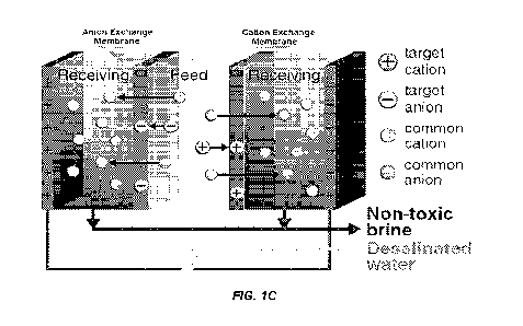
Indeed, functionalized PAP variants have highest selectivities,
kinetic rate constants, and capacities for capturing Hg', Nd', Cu',
Pb2-', UO22, B(OH)3, Fe3-', or AuCld- from water. The disclosure
demonstrates that the exceptional adsorption performances of PAFs
are retained upon incorporation into membrane matrices, thus,
demonstrating the broad potential of PAP-incorporated charged
membranes.
[0085] As described herein, any number of different adsorbents
(e.g., PAFs) can be used in the compositions and methods of the
disclosure. Dimensions of the gas passages, and hence the pressure
drop through the membrane adsorbent bed, can be set by the
characteristic dimension of the adsorbent (e.g., PAP), the density
of adorbent packing, and the dispersity of the adsorbent sizes in
addition to the membrane composition. The absorbent can be a
relatively uniform density. In instances where the absorbent
comprises a porous framework, the pore of the framework can be
functionalized to be selective for a particular ionic charge or
molecular size. In some embodiments, a plurality of differently
functionalized PAFs or absorbents can be present in the membrane
such that the membrane is selective for a plurality of different
agents or contaminants in a fluid stream.
[0086] The adsorbent material can be selected according to the
service needs, particularly the composition of the incoming fluid
stream, the contaminants or agents which are to be removed and the
desired service conditions, e.g., incoming gas pressure and
temperature, desired product composition and pressure. Non-limiting
examples of selective adsorbent materials can include, but are not
limited to, microporous materials such as zeolites, metal organic
frameworks (M0Fs), AlP0s, SAPOs, ZIFs, (Zeolitic Imidazolate
27
CA 03192842 2023- 3- 15
WO 2022/061020
PCT/US2021/050724
Framework based molecular sieves, such as ZIF-7, ZIF-8, ZIF-22,
etc.), and carbons, as well as mesoporous materials such as amine-
functionalized MCM materials, and combinations thereof.
[0087] Various membranes can be used in the methods and
compositions of the disclosure and can be selected for their
particular use and functionalized with an absorbent accordingly.
Membranes suitable for use in the disclosed composites and fluid
separation module include a metallic membrane such as palladium or
vanadium. Alternative membrane embodiments are known to those
skilled in the art, and generally comprise inorganic membranes,
polymer membranes, carbon membranes, metallic membranes, composite
membranes having more than one selective layer, and multi-layer
systems employing non-selective supports with selective layer(s).
Inorganic membranes may be comprised of zeolites, such as small pore
zeolites, microporous zeolite-analogs such as AIPO's and SAPO's,
clays, exfoliated clays, silicas and doped silicas. Inorganic
membranes are typically employed at higher temperatures to minimize
water adsorption. Polymeric membranes typically achieve hydrogen
selective molecular sieving via control of polymer free volume, and
thus are more typically effective at lower temperatures. Polymeric
membranes may be comprised, for example, of rubbers, epoxies,
polysulfones, polyimides, and other materials, and may include
crosslinks and matrix fillers of non-permeable (e.g., dense clay)
and permeable (e.g., zeolites) varieties to modify polymer
properties. Carbon membranes are generally microporous and
substantially graphitic layers of carbon prepared by pyrolysis of
polymer membranes or hydrocarbon layers. Carbon membranes may
include carbonaceous or inorganic fillers, and are generally
applicable at both low and high temperature. Metallic membranes are
most commonly comprised of palladium, but other metals, such as
tantalum, vanadium, zirconium, and niobium are known to have high
and selective hydrogen permeance. Metallic membranes typically have
a temperature- and H2-pressure-dependent phase transformation that
limits operation to either high or low temperature, but alloying
(e.g., with Copper) is employed to control the extent and
temperature of the transition.
28
CA 03192842 2023- 3- 15
WO 2022/061020
PCT/US2021/050724
[0088] PAF-incorporated membranes advantageously exhibit an
inverse effect to the typical permeability-selectivity tradeoff
shown in conventional charged membranes. PAFs add porosity to the
membranes to elevate their water uptake, and these high-diffusivity
pathways in the PAP pores lead to heightened ion conductivities in
PAP-embedded membranes compared to neat, conventional charged
membranes (see FIGs. 49 and 50). However, while increased water
uptake (and thus permeability) in charged membranes typically leads
to increased swelling (and thus decreased selectivity), strong PAP-
polymer crosslinking interactions diminish swelling in water. This
reduced swelling prevents the formation of non-selective pathways in
the polymer matrix.
[0089] This disclosure also provides a multifunctional, one-
step
separation method in which selective and tunable adsorbent particles
or adsorption sites are incorporated into membranes (e.g., the
composite membranes of the disclosure). In this approach, minor
components of interest in a liquid- or gas-phase mixture are
selectively captured by adsorption sites embedded in a membrane as
the components transport through the membrane. Simultaneously, the
feed stream is separated and purified via traditional membrane
transport routes. The compositions and methods of the disclosure
thus allow for the isolation of virtually any targeted component
while simultaneously purifying the feed stream.
[0090] The selective separation of trace components of
interest
from various mixtures (e.g., micropollutants from groundwater,
lithium or uranium from seawater, carbon dioxide from air) presents
an especially pressing technological challenge. The composite
membranes disclosed herein address existing drawbacks by providing
highly selective and tunable adsorbents or adsorption sites which
are embedded into membranes.
[0091] In a particular embodiment, the target species are
selectively captured by the embedded adsorbents or adsorption sites
of the composite membrane disclosed herein while the non-targeted
species can either be transported or not-transported across the
composite membrane. For example, in the exemplary experiments
described herein, a composite membrane comprising incorporated Hg'-
selective adsorbents in an electrodialysis membrane provided for
29
CA 03192842 2023- 3- 15
WO 2022/061020
PCT/US2021/050724
simultaneously capture of He via an adsorption mechanism while
desalinating water through an electrodialysis mechanism. Adsorption
studies demonstrate that the embedded adsorbents maintain rapid,
selective, regenerable, and high-capacity Hg2+ binding capabilities
within the membrane matrix. Furthermore, when inserted into an
electrodialysis setup, the composite membranes successfully capture
all Hg2+ from various Hg2+-spiked water sources while permeating all
other competing cations to simultaneously enable desalination.
Finally, using an array of other ion-selective adsorbents, it was
shown that other composite membranes could be produced which
targeted a variety of ions that can be found in water sources. The
composite membranes of the disclosure can be applied to existing
membrane processes to efficiently capture targeted species of
interest, without the need for additional expensive equipment or
processes such as fixed-bed adsorption columns.
[0092] A schematic illustration of an ion-capture
electrodialysis (IC-ED) design is depicted in Fig. 1C. As with
conventional electrodialysis processes, an external voltage is
applied to generate an electric potential gradient to drive cations
and anions in the toxic, saline feed toward opposite directions.
With selective cation-capture and anion-capture membranes placed in
between the two electrodes in our system, competing ions permeate
through the membranes freely to desalinate the feed, while target
ions are captured by adsorbents dispersed in the membranes.
Selective adsorption sites can also be grafted directly to the
membrane matrix.
[0093] A system of the disclosure as set for in Fig. 1C can
comprise (i) a composite anionic membrane comprising selective
absorbents for anionic agents in a feed fluid stream, (ii) a
composite cationic membrane comprising selective absorbents for
cationic agents in a feed fluid stream, or (iii) both (i) and (ii).
[0094] The composite membranes of the disclosure can be used
to
(1) capture target ions as they permeate through a membrane, (2)
desalinate and decontaminate feed water streams for reuse, and/or
(3) obtain receiving solutions (e.g., brine) that are non-toxic.
Moreover, the composite membranes of the disclosure can provide for
all the foregoing in a simultaneous manner. Additionally, the
CA 03192842 2023- 3- 15
WO 2022/061020
PCT/US2021/050724
disclosure provides for composite membranes in an adsorbent-based
fluid separation membrane, the target molecule (e.g., mercury,
sulfur compounds, carbon dioxide) is captured by selective binding
sites, while the feed is simultaneously separated into retentate and
permeate streams with permeate/retentate separation factors
determined by the choice of membrane matrix material used. These
goals are in conjunction with other variations of multifunctional
separations described later in this disclosure that likewise utilize
adsorbent-based membranes. For example, in an adsorbent-based gas
separation membrane, the target molecule (e.g., mercury, sulfur
compounds, carbon dioxide) is captured by selective binding sites,
while the feed is simultaneously separated into retentate and
permeate streams with permeate/retentate separation factors
determined by the choice of membrane matrix material used.
[0095] While this approach can be used to capture any targeted
anion or cation using high performance adsorbents selective for each
given species, this was characterized using Hg', one of the most
prevalent and toxic waterborne micropollutants, as a model target
species. A Hg'-selective porous aromatic framework functionalized
with thiol groups (PAF-1-SH) was used as the model adsorbent and was
dispersed in a sulfonated polysulfone (sPSF) cation conducting
membrane matrix.
[0096] To assess the multifunctional IC-ED process for
treating
virtually any feed mixture, 20 wtS PAF-1-SH membranes were tested
for the Hg'-capture electrodialysis of 5 ppm Hg' spiked in
synthetic groundwater, brackish water, and industrial wastewater.
These feed sources were chosen for their diversity of salinity
levels, ion types, and pH (Tables D and E). In these proof-of-
concept experiments, a custom-made two-compartment cell was used,
with the cation-capture membrane separating the feed from the
"receiving" solution (10 mM HNO3, to maintain conductivity and
prevent metal precipitation). -4 V vs. Ag/AgC1 were applied to drive
feed cations through the membrane toward the receiving solution, and
ion concentrations in both solutions were periodically measured.
Remarkably, for each water source, Hg' was entirely captured by the
adsorptive membranes, as Hg' was selectively reduced to
concentrations below detection in the feed without permeating into
31
CA 03192842 2023- 3- 15
WO 2022/061020
PCT/US2021/050724
the receiving solution. Meanwhile, all competing cations (Na+, K+,
Mg', Ca', Ba", Mn', Fe', Ni', Cu', Zn', Cd', Pb") successfully
transported into the receiving solution to achieve over 97-99%
desalination of the feed. Desalination percentages were calculated
based on the changes in the sum of the cation feed concentrations.
No Hg' was captured when using conventional neat sPSF cation
exchange membranes. These findings are summarized in Table G and
highlight the unique and exceptionally selective multifunctional
separation capabilities of an IC-ED method utilizing adsorptive
membranes.
[0097] Breakthrough experiments were also conducted to reveal
what percentage of embedded adsorption sites can be utilized in a
multifunctional adsorbent-based membrane separation process. In
these tests, a feed containing a high Hg" concentration (-100 ppm)
in a 0.1 M NaNO3 supporting electrolyte was used along with a 1 mM
HNO3 receiving solution. Hg' concentrations were periodically
tracked to identify the "breakthrough time" at which Hg was first
detected in the receiving solution instead of captured in the
membrane. As expected, Hg' immediately permeated through a neat sPSF
membrane without the adsorbent. Conversely, the breakthrough time by
a 20 wt-(-5 PAF-l-SH membrane was approximately twice of that by a 10
wt% membrane, indicating high ion-capture efficiency. To
quantitatively evaluate the percentage of membrane-embedded
adsorbents that are utilized before breakthrough is reached in an
IC-ED setup, the receiving Hg' concentrations were plotted against
the amount of Hg' captured by PAFs in the membrane. Astonishingly,
both the 10 wt% and 20 wtS PAF membranes experienced breakthrough
after nearly all (97%) of the embedded adsorption sites were
utilized, based on the Hg' equilibrium adsorption capacity attained
by accessible PAF-1-SH powder at approximately equivalent testing
conditions. These findings prove that high performance adsorption
sites embedded in a membrane can be applied for the highly efficient
and selective capture of target species when employed in a membrane
separation process.
[0098] The disclosure is a generalizable and tunable approach
applicable to virtually any target species. To validate this
versatility, sPSF membranes were tuned to contain other high-
32
CA 03192842 2023- 3- 15
WO 2022/061020
PCT/US2021/050724
performance adsorbents highly selective for other common waterborne
contaminants (PAF-1-SMe10 for Cu2+ and PAF-1-ET11 for Fe3+).
Membranes composed 20 wt% of PAF-I-SMe or PAT-I-ET were then tested
in the IC-ED setup. Feed solutions of 6 ppm Cu2+ or 2.3 ppm Fe3+,
respectively, in 0.1 M HEPES buffer (to supply competing ions and
prevent precipitation upon OH- generation) were used. Excitingly,
similar to in the Hg2+-capture electrodialysis tests, both membranes
selectively captured their respective target ions entirely while
achieving at least 96% desalination of the feeds to simultaneously
produce reusable water. This ion capture behavior is absent when
neat sPSF membranes without the adsorbents is used, highlighting the
unique and highly selective transport properties of an adsorbent
embedded membrane process.
[0099] To show that this can also be applied generally to
other
membrane processes, membranes were fabricated containing the B(OH)3-
selective adsorbent PAF-l-NMDG. Membranes composed 20 wti; of PAF-1-
NMDG in a sPSF matrix were placed in a diffusion dialysis setup
without an applied electric field. Synthetic groundwater spiked with
4.5 ppm B(OH)3 was inserted into the feed half-cell, while the
receiving half-cell was charged with deionized water. In these
tests, a concentration gradient, rather than primarily an electric
potential gradient, drove solute transport across the membrane. 20
wt% PAF-1-NMDG membranes completely captured B(OH)3 as it
transported through the membrane, as B(OH)3 was reduced to
concentrations below detection in the feed without any measured
permeation into the receiving solution. No appreciable B(OH)3 was
captured when a neat sPSF membrane was used. Membranes containing
the Hg'-selective PAF-1-SH also exhibited selective target species
capture when employed in a solute-capture diffusion dialysis setup.
Hence, the selective capture of various target species can be
achieved by membranes containing selective adsorption sites
regardless of the type of membrane separation process used, as
different species transport driving forces can be applied.
[00100] For a general multifunctional adsorption-based membrane
separation process to be effective, the following performance
standards are suggested: (1) Binding groups must remain accessible
within the membrane matrix. (2) Adsorbate binding rates must be
33
CA 03192842 2023- 3- 15
WO 2022/061020
PCT/US2021/050724
faster than adsorbate transport rates through the membrane. (3) The
adsorbent-based membrane must be regenerable such that adsorption
sites are reusable and target adsorbates are recoverable. (4) The
adsorbent-based membrane must possess sufficiently high selectivity
toward the target adsorbates such that only the target adsorbates
are captured. Competing species are not captured by the membrane and
are instead rejected by or permeated through the membrane for
purification of the inlet stream.
[00101] Through batch adsorption studies, each of these
performance standards were indeed achieved by model adsorbent-based
membranes consisting of PAF-1-SH embedded in sPSF. These studies can
be used to predict the efficiency of adsorption sites incorporated
in any membrane before use in a multifunctional membrane separation
process.
[00102] To evaluate the first standard, membrane equilibrium
adsorption isotherms were collected and compared to expected mass-
averaged values based on the individual saturation adsorption
capacities for the bare membrane matrix and adsorbent particles. In
these experiments, neat sPSF membranes, PAF-1-SH bulk powder, and 20
PAF-l-SH membranes were stirred until reaching equilibrium (at
least 12 h for bulk PAF-1-SH or 48 h for membranes) in aqueous
solutions containing varied initial Hg21 concentrations. The initial
and final concentrations were measured to extract equilibrium
adsorption capacities. Based on the measured He saturation capacity
for the 20 wt% PAF-1-SH membranes compared to the theoretical
maximum capacity, the percentage of PAF-l-SH adsorbent sites that
remain accessible within the membrane matrix was determined to be as
high as 93%.
[00103] To assess the second and third standards, adsorption
kinetics and adsorption regeneration measurements were collected. In
the kinetics studies, bulk PAF-1-SH was stirred in an aqueous
solution containing 100 ppm Hg', and adsorption capacities were
measured over time. These measurements indicate that the Hg' binding
kinetics of the adsorbents are nearly instantaneous: over 81% of the
Hg' saturation capacity is reached within the first 10 s of
adsorption. In the regeneration studies, 20 wt% PAF-1-SH membranes
were stirred for at least 48 h in an aqueous solution containing 100
34
CA 03192842 2023- 3- 15
WO 2022/061020
PCT/US2021/050724
ppm Hg'. The membranes were then immersed in concentrated HC1
followed by 2 M NaNO3 to desorb and recover the captured Hg2+ while
regenerating thiol adsorption groups in the membranes. After
repeating these adsorption and desorption experiments over 10
cycles, only an 8% loss in Hg2+ capacity was observed, and the
adsorption capacity remained approximately constant after the third
cycle.
[00104] To investigate the fourth standard, equilibrium
adsorption selectivity tests were performed. Bulk PAF-1-SH powder
was stirred until reaching adsorption equilibrium in aqueous
solutions of 100 ppm He spiked in various prevalent water supply
sources (groundwater, brackish water, industrial wastewater, or
seawater; see Tables A and B). The initial and final concentrations
of each solution were measured to obtain adsorption capacities. No
loss in He capacity was observed upon the presence of various
abundant competing ions in each solution, indicating that the model
PAF-1-SH adsorbents possess near-perfect multicomponent selectivity
for Hg'. These experiments were also repeated using membranes
consisting of neat sPSF for comparison and 20 wt% PAF-1-SH. Ultra-
high Hg' selectivity was preserved in the PAF-i-SH adsorption sites
upon incorporation into a membrane polymer matrix, as the 20 wt,5
PAF-1-SH membranes achieved adsorption capacities matching those
expected. Expected capacities were determined as the mass-averaged
capacity based on the individual PAF-1-SH and sPSF adsorption
uptakes. Results from these four performance standards indicate that
the performance characteristics of adsorbents can be retained upon
incorporation into membrane matrices, enabling their use in
multifunctional adsorbent-based membrane separations as described in
this disclosure.
[00105] The disclosure provides compositions and methods for
selective capture of targeted components in any existing industrial
process that uses membranes, provided that traditional membranes
used in these processes are instead replaced with adsorbent-based
composite membranes as described by the disclosure. Tunable
multifunctional membrane of the disclosure can also obviate the need
for additional industrial adsorption units, such as pressure swing
adsorption or temperature swing adsorption technologies. Examples of
CA 03192842 2023- 3- 15
WO 2022/061020
PCT/US2021/050724
potential applications and variations of the described disclosure
include, but are not limited to, the following: (1) Selective
recovery of targeted ions (e.g., organic ions, charged dyes, heavy
metals, lithium, charged water pollutants) in liquid mixtures via
charge-based separations. As provided herein, these separations can
be achieved via ion-permeable membranes modified with adsorption
sites or embedded with adsorbents that are selective for the
targeted ions. Examples of traditional charge-based membrane
separations in which adsorbent-embedded membranes can be implemented
include electrodialysis, membrane capacitive deionization, and
electrofiltration. In these cases, an electric potential gradient
drives ion transport across the membrane, where target ions can then
be captured. Water desalination can also be simultaneously achieved
with selective ion recovery. (2) Using principles described herein,
selective adsorbents can additionally be mixed directly into porous
electrodes to capture target ions that transport into the
electrodes. This approach could especially be effective in
capacitive deionization separations to enable highly selective
target ion recovery. In general, selective adsorption sites can be
embedded into or onto various matrices (polymers, films, electrodes,
etc.) through which the target component is permeable or to which
the target ion contacts exposed adsorption sites on the surface of
the matrix, to selectively capture the target component. (3)
Selective recovery of charged or uncharged solutes using a solute-
capture diffusion dialysis or solute-capture Donnan Dialysis
approach implemented with adsorptive membranes. In this case,
concentration gradients drive solute transport across the adsorptive
membranes, where the target solute is selectively captured by
adsorption sites incorporated in the membranes. (4) Selective
capture of contaminants in fuel cell operations. For instance, these
contaminants may be species like carbon monoxide or sulfur compounds
that traditionally transport undesirably across the fuel cell
membrane and subsequently poison the fuel cell catalyst. In
accordance with the disclosure, membranes that contain adsorption
sites selective for these contaminants (e.g., NafionT' membranes
embedded with selective adsorbents) may replace traditional
contaminant-permeable membranes used in existing fuel cell
36
CA 03192842 2023- 3- 15
WO 2022/061020
PCT/US2021/050724
operations (e.g., neat NafionT' membranes). Using such adsorbent-
based membranes, normal fuel cell operations can be performed while
the contaminants are selectively captured concurrently. (5)
Selective removal of contaminants in gas mixtures. For example,
these contaminants may be species like mercury in coal flue gas
mixtures or trace oxygen in inert gas mixtures. In accordance with
disclosure, membranes that contain adsorption sites selective for
these contaminants (e.g., membranes embedded with mercury-selective
PAF-1-SH adsorbents) may act as a filter through which these gas
mixtures transport to selectively capture the contaminants and
permeate competing components. Such adsorbent-based membranes can
also be applied in a multifunctional gas separation approach to
replace traditional membranes used in gas separations. In this
multifunctional approach, contaminants can be selectively captured
as the feed gas mixture simultaneously separates into retentate and
permeate streams with different compositions. In this case,
contaminant selectivity in these composite membranes is dictated by
the choice of embedded adsorption sites, while separation factors
and permeabilities of the feed gas mixture are dictated by the
choice of membrane polymer matrix. (6) Selective capture of CO; from
the atmosphere. In accordance with this disclosure, membranes
modified with strong CO2-selective binding sites (e.g., amine- or
polyamine appended, adsorbents) can act as a filter for direct air
capture through which air is transported. During the transport of
air through the adsorbent-based membrane, CO2 in the air (present at
a trace concentration of -410 ppm13) can be captured to yield a
permeate stream with a reduced CO2 concentration. CO2 can then be
recovered from the embedded adsorbents (e.g., via a temperature
swing) for subsequent CO2 utilization or sequestration. Similar
strategies can be employed for the selective capture of other air
pollutants (e.g., aldehydes) using adsorptive membranes selective
for these pollutants. (7) Selective capture of dissolved CO2 or CO2-
derived compounds (e.g., HCO3) from water. In accordance with this
disclosure, membranes modified with strong CO2-selective binding
sites can be implemented for the capture of dissolved CO2 or CO2-
derived compounds, which often undesirably alter solution pH and
lead to ocean acidification. These CO2-adsorbing membranes can be
37
CA 03192842 2023- 3- 15
WO 2022/061020
PCT/US2021/050724
implemented into existing water treatment membrane processes (e.g.,
electrodialysis, reverse osmosis) or can be used as a filter through
which aqueous solutions pass to exclusively capture the CO,
compounds. When implemented into existing desalination technologies,
the simultaneous desalination of water and capture of CO2 or CO2-
derived compounds can be achieved within the same unit. (8)
Selective capture and recovery of target compounds (e.g.,
contaminants or high-value compounds) in liquid mixtures using
adsorbent-modified microfiltration, ultrafiltration, nanofiltration,
or reverse osmosis membranes. In accordance with this disclosure,
adsorbents or adsorption sites selective for these target compounds
can be blended into any part of the membrane matrices, embedded into
the membrane porous support layers, and/or grafted onto the top
layer of the membrane (i.e., side of membrane active layer that
faces the feed influent stream). As an example, adsorbents selective
for boric acid, a common seawater pollutant that desalination
membranes cannot efficiently reject, can be incorporated into
reverse osmosis membranes for the simultaneous desalination of water
and removal of boron in the same unit. Other examples of target
compounds that adsorbent-based filtration membranes, unlike
traditional filtration membranes, can be used for include
pharmaceuticals, viruses, neutral organic micropollutants, small
molecules in liquid fuel or organic solvent streams, and undesirable
isomers in isomeric mixtures. Drug purification processes used in
the pharmaceutical industry can also utilize adsorbent-based
membranes innovated in this invention to obviate the need for other
column purification units. (9) Selective removal of toxins from
blood. In accordance with this disclosure, adsorbents or adsorption
sites selective for these toxins can be blended into hemodialysis
(i.e., blood dialysis) membranes, embedded into the membrane porous
support layers, and/or grafted onto the top layer of the membranes.
In this design, blood can be purified without the typical release of
toxins into the dialysate solution, potentially allowing the
dialysate to be recycled rather than disposed. Similar adsorbent-
based membranes can also be applied as a filter through which
contaminated blood solutions (e.g., from individuals with blood
poisoning) transport to selectively remove the toxins from blood.
38
CA 03192842 2023- 3- 15
WO 2022/061020
PCT/US2021/050724
(10) Selective capture of target compounds in organic liquid
mixtures using adsorbent modified pervaporation or membrane
distillation membranes. In accordance with this disclosure,
adsorbents or adsorption sites selective for these target compounds
can be blended into any part of the membrane matrices, embedded into
the membrane porous support layers, and/or grafted onto the top
layer of the membrane. Unlike in traditional pervaporation or
membrane distillation processes, multifunctional separations
utilizing adsorbent-based membranes can be achieved in which target
compounds are captured while the feed mixture, following
conventional pervaporation and membrane distillation principles, is
separated into retentate and permeate mixtures with different
desirable compositions. (11) As a variation to the materials and
processes innovated by this disclosure, membranes with tunable
catalytic sites, rather than tunable adsorption sites, can be
developed using principles created in this invention. In this case,
catalytic particles or reactive sites can be embedded into or
appended onto a membrane matrix to create reactive membranes. In
accordance with this disclosure, such reactive membranes can be used
for the simultaneous separation of a feed mixture and conversion of
a target component into a more desirable product. This desirable
product can either be isolated following desorption from the
membrane or can permeate through the membrane directly after
conversion. Reactive membranes can also be applied for general
catalytic applications. (12) The compositions and methods of the
disclosure can also be used as a pretreatment or post-treatment step
in various industrial processes, to partially or completely reduce
the concentration of targeted components from mixtures. For example,
this invention can be used to selectively recover nutrients from
streams in a wastewater treatment plant or high-value components
from brine effluent streams in a reverse osmosis plant. (13) This
disclosure can additionally be applied as a replacement unit to
existing fixed-bed adsorption columns for improved separations.
While fixed-bed adsorption processes are a mature and developed
technology, membrane separations are often more energy efficient and
may possess fewer mass transfer limitations for improved separation
selectivities. (14) As an analogous variation to the adsorbent-based
39
CA 03192842 2023- 3- 15
WO 2022/061020
PCT/US2021/050724
membranes described in this disclosure, multiple different types of
selective adsorbents or adsorption sites can be incorporated into
the same membrane. Accordingly, these membranes can be used to
capture multiple different target components within the same
membrane. Similarly, multiple adsorbent based membranes selective
for different target components can be placed sequentially in a
multi-stage process, such as placed side-by-side in the same
electrodialysis stack, to capture each target component in a
stepwise fashion.
[00106] The composite membranes disclosed herein can be used as
cation- or anion-exchange membranes or bipolar membranes used for
water purification or water desalination. In this context,
electrodialysis, Donnan Dialysis, and membrane capacitive
deionization are three example technologies in which charged
membranes incorporated with MOFs, COFs, ZIFs and/or PAFscan be used
to achieve improved separation performances compared to those by
conventional membranes. The composite membranes of the disclosure
may also be used for other applications of these technologies, such
as in the food processing industry.
[00107] The composite membranes disclosed herein can be used as
fuel cell membranes (e.g., proton- or hydroxide-exchange membranes)
with improved performance and stability compared to conventional
neat membranes. The composite membranes as described herein may be
used in place of traditional fuel cell membranes, to increase
chemical stability (e.g., in organic solvents), pH stability,
thermal stability, dimensional stability (i.e., swelling
resistance), ion conductivity, and ion-exchange capacities.
[00108] The composite membranes disclosed herein can be used as
reverse electrodialysis membranes for blue energy harvesting. In
this technology, charged membranes are placed between a high-
salinity aqueous solution (e.g., seawater) and a low-salinity
aqueous solution (e.g., river water). These salinity gradients
across the membranes generate an electrochemical potential
difference that can be harvested as energy ("blue energy").
Previously described improvements achieved by the composite
membranes disclosed herein compared to conventional membranes, such
CA 03192842 2023- 3- 15
WO 2022/061020
PCT/US2021/050724
as decreased ionic resistance, may be exploited for this
application.
[00109] The composite membranes disclosed herein can be used as
charged membranes used for other general electrochemical
applications that utilize a membrane, such as flow batteries.
Previously described improvements achieved by the composite
membranes disclosed herein compared to conventional membranes may be
exploited for various electrochemical applications.
[00110] The composite membranes disclosed herein can be used as
charged membranes used for selective ion separations. For example,
PAFs can be incorporated into monovalent-selective polymer matrices
to achieve improved separation performances for monovalent ions
(e.g., Li') over other ions. Additionally, the composite membranes
of the disclosure can be tuned to create targeted pore sizes that
enable molecular sieving can be incorporated into charged membranes
to enhance molecular selectivity.
[00111] The composite membranes disclosed herein can be used as
adsorptive membranes selective for targeted molecules, such as
contaminants or high-value ions in water. PAFs selective for various
waterborne species, as previously discussed, can be loaded into
membranes to increase the capacity and selectivity for these species
in the composite membranes of the disclosure. The selectivity of the
composite membranes of the disclosure can be tuned according to the
functional group and pore environment of the chosen MOFs, COFs, ZIFs
and/or PAFs. Such adsorptive membranes can be used in place of
adsorption columns, membrane adsorbers, or other adsorption
technologies.
[00112] The composite membranes can be used for selective
recovery of targeted ions (e.g., organic ions, charged dyes, heavy
metals, lithium, charged water pollutants) in liquid mixtures via
charge-based separations. As provided herein, these separations can
be achieved via ion-permeable membranes modified with PAFs that are
selective for the targeted ions. Examples of traditional charge-
based membrane separations in which PAF-embedded membranes can be
implemented include electrodialysis, membrane capacitive
deionization, and electrofiltration. In these cases, an electric
potential gradient drives ion transport across the membrane, where
41
CA 03192842 2023- 3- 15
WO 2022/061020
PCT/US2021/050724
target ions can then be captured. Water desalination can also be
simultaneously achieved with selective ion recovery.
[00113] Using the techniques described herein, selective MOFs,
COFs, ZIFs and/and/or PAFs can additionally be mixed directly into
porous electrodes to capture target ions that transport into the
electrodes. This approach could especially be effective in
capacitive deionization separations to enable highly selective
target ion recovery. In general, selective MOFs, COFs, ZIFs, and/or
PAFs can be embedded into or onto various matrices (polymers, films,
electrodes, etc.) through which the target component is permeable or
to which the target ion contacts exposed adsorption sites on the
surface of the matrix, to selectively capture the target component.
[00114] The composite membranes disclosed herein can be used
for
selective capture of contaminants in fuel cell operations. For
instance, these contaminants may be species like carbon monoxide or
sulfur compounds that traditionally transport undesirably across the
fuel cell membrane and subsequently poison the fuel cell catalyst.
In accordance with this disclosure, composite membranes that contain
MOFS, COFs, ZIFs and/or PAFs selective for these contaminants (e.g.,
NafionTM membranes embedded with selective MOFS, COFs, ZIFs and/or
PAFs) may replace traditional contaminant-permeable membranes used
in existing fuel cell operations (e.g., neat Nafion'' membranes).
Using such composite membranes, normal fuel cell operations can be
performed while the contaminants are selectively captured
concurrently.
[00115] The composite membranes disclosed herein can be used
for
selective removal of contaminants in gas mixtures. For example,
these contaminants may be species like mercury in coal flue gas
mixtures or trace oxygen in inert gas mixtures. In accordance with
this disclosure, composite membranes that contain MOFS, COFs, ZIFs
and/or PAFs selective for these contaminants (e.g., membranes
embedded with mercury-selective MOFS, COFs, ZIFs and/or PAFs
adsorbents) may act as a filter through which these gas mixtures
transport to selectively capture the contaminants and permeate
competing components. Such composite membranes can also be applied
in a multifunctional gas separation approach to replace traditional
membranes used in gas separations. In this multifunctional approach,
42
CA 03192842 2023- 3- 15
WO 2022/061020
PCT/US2021/050724
contaminants can be selectively captured as the feed gas mixture
simultaneously separates into retentate and permeate streams with
different compositions. In this case, contaminant selectivity in
these composite membranes is dictated by the choice of embedded
MOFS, COFs, ZIFs and/or PAFs, while separation factors and
permeabilities of the feed gas mixture are dictated by the choice of
membrane polymer matrix.
[00116] The composite membranes disclosed herein can be used
for
selective capture of CO2 from the atmosphere. In accordance with
this disclosure, membranes modified with strong CO2-selective MOFs,
COFs, ZIFs and/or PAFs (e.g., amine- or polyamine functionalized
frameworks) can act as a filter for direct air capture through which
air is transported. During the transport of air through the
composite membrane, CO2 in the air (present at a trace concentration
of -410 ppm) can be captured to yield a permeate stream with a
reduced CO2 concentration. CO2 can then be recovered from the
embedded MOFs, COFs, ZIFs and/or PAFs (e.g., via a temperature
swing) for subsequent CO2 utilization or sequestration. Similar
strategies can be employed for the selective capture of other air
pollutants (e.g., aldehydes) using composite membranes selective for
these pollutants.
[00117] The composite membranes disclosed herein can be used
for
the selective capture of dissolved CO2 or CO2-derived compounds
(e.g., HCO3) from water. In accordance with this disclosure,
composite membranes comprising MOFs, COFs, ZIFs and/or PAFs that
have strong CO2-selective binding sites can be implemented for the
capture of dissolved CO2 or CO2-derived compounds, which often
undesirably alter solution pH and lead to ocean acidification.
These composite membranes can be implemented into existing water
treatment membrane processes (e.g., electrodialysis, reverse
osmosis) or can be used as a filter through which aqueous solutions
pass to exclusively capture the CO, compounds. When implemented into
existing desalination technologies, the simultaneous desalination of
water and capture of CO2 or CO2-derived compounds can be achieved
within the same unit.
[00118] The composite membranes disclosed herein can be
selective
capture and recovery of target compounds (e.g., contaminants or
43
CA 03192842 2023- 3- 15
WO 2022/061020
PCT/US2021/050724
high-value compounds) in liquid mixtures using a composite membrane
as microfiltration, ultrafiltration, nanofiltration, or reverse
osmosis membranes. In accordance with this disclosure, MOFs, COFs,
ZIFs and/or PAFs selective for these target compounds can be blended
into any part of the membrane matrices, embedded into the membrane
porous support layers, and/or grafted onto the top layer of the
membrane (i.e., side of membrane active layer that faces the feed
influent stream). As an example, MOFs, COFs, ZIFs and/or PAFs
selective for boric acid, a common seawater pollutant that
desalination membranes cannot efficiently reject, can be
incorporated into reverse osmosis membranes for the simultaneous
desalination of water and removal of boron in the same unit. Other
examples of target compounds that adsorbent-based filtration
membranes, unlike traditional filtration membranes, can be used for
include pharmaceuticals, viruses, neutral organic micropollutants,
small molecules in liquid fuel or organic solvent streams, and
undesirable isomers in isomeric mixtures. Drug purification
processes used in the pharmaceutical industry can also utilize
composite membranes described herein to obviate the need for other
column purification units.
[00119] The composite membranes disclosed herein can be
selective
removal of toxins from blood. In accordance with this disclosure,
composite membranes comprising MOFs, COFs, ZIFs and/or PAFs
selective for these toxins can be used as hemodialysis (i.e., blood
dialysis) membranes, embedded into the membrane porous support
layers, and/or grafted onto the top layer of the membranes. In this
design, blood can be purified without the typical release of toxins
into the dialysate solution, potentially allowing the dialysate to
be recycled rather than disposed. Similar composite membranes can
also be applied as a filter through which contaminated blood
solutions (e.g., from individuals with blood poisoning) transport to
selectively remove the toxins from blood.
[00120] The composite membranes disclosed herein can be
selective
capture of target compounds in organic liquid mixtures using MOF,
COF, ZIF and/or PAF modified pervaporation or membrane distillation
membranes. In accordance with this disclosure, MOFs, COFs, ZIFs
and/or PAFs selective for these target compounds can be blended into
44
CA 03192842 2023- 3- 15
WO 2022/061020
PCT/US2021/050724
any part of the membrane matrices, embedded into the membrane porous
support layers, and/or grafted onto the top layer of the membrane.
Unlike in traditional pervaporation or membrane distillation
processes, multifunctional separations utilizing composite membranes
can be achieved in which target compounds are captured while the
feed mixture, following conventional pervaporation and membrane
distillation principles, is separated into retentate and permeate
mixtures with different desirable compositions.
[00121] As a variation to the materials and processes innovated
by this disclosure, membranes with tunable catalytic sites, rather
than tunable adsorption sites, can be developed using principles
described herein. In this case, catalytic MOFs, COFs, ZIFs and/or
PAFs can be embedded into or appended onto a membrane matrix to
create catalytically active composite membranes. In accordance with
this disclosure, such composite membranes can be used for the
simultaneous separation of a feed mixture and conversion of a target
component into a more desirable product. This desirable product can
either be isolated following desorption from the membrane or can
permeate through the membrane directly after conversion. Composite
membranes can also be applied for general catalytic applications.
[00122] The composite membranes described herein can be used as
a
pretreatment or post-treatment step in various industrial processes,
to partially or completely reduce the concentration of targeted
components from mixtures. For example, the composite membranes can
be used to selectively recover nutrients from streams in a
wastewater treatment plant or high-value components from brine
effluent streams in a reverse osmosis plant.
[00123] The composite membranes of the disclosure can be
applied
as a replacement unit to existing fixed-bed adsorption columns for
improved separations. While fixed-bed adsorption processes are a
mature and developed technology, membrane separations are often more
energy efficient and may possess fewer mass transfer limitations for
improved separation selectivities.
[00124] The composite membranes of the disclosure can
incorporate
various types of MOFs, COFs, ZIFs and/or PAFs, in addition to the
PAFs exemplified herein. In this case, the PAFs may be synthesized
through an irreversible coupling reaction using other organic nodes,
CA 03192842 2023- 3- 15
WO 2022/061020
PCT/US2021/050724
aromatic linkers, or functionalized chemical appendages. Other
examples of PAFs that can be used with the composite membranes of
the disclosure, include but are not limited to, Scholl-coupled PAFs
that are relatively inexpensive, PAFs or COFs with anionic borate
nodes, or catalytic MOFs, COFs, ZIFs or PAFs. Charged frameworks
(e.g., MOFs, COFs, ZIFs and/or PAFs with anionic borate nodes or
appended with charged groups) can also be embedded into neutral
membranes to create charged composite membranes as discussed in this
disclosure.
[00125] The composite membranes of the disclosure may comprise
different polymer matrices, in addition to the sulfonated
polysulfone polymer matrix exemplified herein. Other examples, of
polymer matrices that can be used with MOFs, COFs, ZIFs and/or PAFs
disclosed herein include perfluorinated sulfonic-acid (PFSA)
ionomers and sulfonated polystyrene. The composite membranes of the
disclosure may also comprise polymer matrices composed of multiple
different charged polymers (e.g., bipolar membranes or copolymers)
with MOFs, COFs, ZIFs and/or PAFs to yield improved composite
membrane properties.
[00126] The disclosure provides for composite membranes that
can
be applied generally to various technologies that use ion-exchange
membranes, or to adsorption processes where composite membranes
detailed herein can be applied as membrane adsorbents. The composite
membranes described herein can be applied for the selective capture
of targeted components in any existing industrial process that uses
membranes, provided that traditional membranes used in these
processes are instead replaced with the composite membranes
described herein. The composite membrane of the disclosure can also
obviate the need for additional industrial adsorption units, such as
pressure swing adsorption or temperature swing adsorption
technologies.
[00127] As described herein, any number of MOFs, COFs, ZIFs
and/or PAFs can be used in the composite membranes and methods of
the disclosure. Dimensions of the gas passages, and hence the
pressure drop through the membrane adsorbent bed, can be set by the
characteristic dimension of the MOFs, COFs, ZIFs and/or PAFs, the
density of MOF, COF, ZIF and/or PAF packing, and the dispersity of
46
CA 03192842 2023- 3- 15
WO 2022/061020
PCT/US2021/050724
the adsorbent sizes in addition to the membrane composition. The
MOFs, COFs, ZIFs and/or PAFs can be a relatively uniform density.
[00128] The MOFs, COFs, ZIFs and/or PAFs can be selected
according to the service needs, particularly the composition of the
incoming fluid stream, the contaminants or agents which are to be
removed and the desired service conditions, e.g., incoming gas
pressure and temperature, desired product composition and pressure.
Non-limiting examples of framework materials that can be
incorporated into the composite membranes disclosed herein can
include, but are not limited to, microporous materials such as
zeolites, metal organic frameworks (MOFs) , COFs, ZIFs, (ZIF based
molecular sieves, such as ZIF-7, ZIF-8, ZIF-22, etc.), AlP0s, SAPOs;
as well as mesoporous materials such as amine-functionalized MCM
materials, and combinations thereof.
[00129] These possibilities hold promise for the development of
a
wide range of potential PAFs to be incorporated into charged
membranes to tune adsorptive, transport, and physical properties of
the composite membranes for numerous desired applications (see FIG.
51).
EXAMPLES
[00130] Synthesis and membrane fabrication. Carbon, hydrogen,
nitrogen, and sulfur elemental analyses were obtained from the
Microanalytical Facility at the University of California, Berkeley
using a PerkinElmer 2400 Series II combustion analyzer. All porous
aromatic framework (PAF) syntheses were performed using Schlenk
techniques under an argon atmosphere. Ultrapure deionized (DI) water
(18.2 MQ cm electrical resistivity and less than 5.4 ppb total
organic carbon) from a Millipore RiOs system was used as the water
source for all syntheses and experiments. All starting materials and
reagents were purchased from Sigma-Aldrich, Alfa Aesar, or Acros
Organics and used as received unless otherwise stated.
[00131] Synthesis of sulfonated polysulfone (sPSF) membrane
matrix polymer. Sulfonated polysulfone (sPSF) was chosen as the
cation exchange polymer matrix due to its extensive use in water
purification applications. The reaction scheme for the sulfonation
of polysulfone (PSF) is shown in Fig. 5. PSF resin (Mw = 60,000) was
first completely dried in a vacuum oven (24 h, 120 C). In a 250-mL
47
CA 03192842 2023- 3- 15
WO 2022/061020
PCT/US2021/050724
round-bottom flask, the dried resin (6 g) was completely dissolved
in CHC13 (120 g, 80 mL). The mixture was capped with a rubber septum
and lightly purged with desiccated N2 for 10 min while stirring to
remove moisture from the headspace. While vigorously stirring at
room temperature, chlorosulfonic acid (750 pL) was slowly added
dropwise using a glass syringe to immediately afford a deep pink
precipitate. The capped mixture was vigorously stirred for 2.5 h and
then poured into a 600-mL ice bath. After washing several times with
DT water, the precipitate was collected and dried on a hot plate for
30 min each at the following temperatures in succession: 60, 75, 90,
110 C. After each 30 min heating step, the solids were mechanically
broken into small pieces for ease of handling. Finally, the sPSF was
dried overnight in a vacuum oven at 80 C to obtain -6.6 g of faint
pink solids. The degree of sulfonation, defined here as sulfonate
groups per PSF repeat unit, was found to be 60. Using the above
protocol, reactions were also carried out using different molar
ratios of chlorosulfonic acid and dried PSF to verify that this
procedure can be used to reproducibly control the degree of
sulfonation.
[00132] Synthesis of PAF-1. The reaction scheme for the
synthesis
and post-synthetic functionalization of PAF-1 is displayed in Fig.
5. The monomer tetrakis(4-bromophenyl)methane was synthesized as a
dark orange powder starting from triphenylmethyl chloride. Before
use, column chromatography using SiO2 (ROCC, 60 A, 40-63 um) and
hexanes as the eluent was used to purify the monomer as a fluffy
white powder before drying under vacuum overnight at 80 C.
[00133] A 500-mL two-neck Schlenk flask was charged with dried
2,2'-bipyridyl (1.1 g, 7.3 mmol), 1,5-cyclooctadiene (0.90 mL, 7.3
mmol), and anhydrous N,N-dimethylformamide (DMF, 110 mL) under an
argon atmosphere. The sealed Schlenk flask was transferred to an Ar-
purged glove tent, where bis(1,5-cyclooctadiene)nickel(0) (2.0 g,
7.3 mmol) was quickly added before a custom-made, air-free solid
transfer adapter containing dried tetrakis(4-bromophenyl)methane
(0.93 g, 1.5 mmol) was connected to the flask. The flask was
resealed in the glove tent, and the solution was heated to 80 C and
stirred for 1.5 h to obtain a deep purple solution. The tetrakis(4-
bromophenyl)methane was then slowly added to the solution under
48
CA 03192842 2023- 3- 15
WO 2022/061020
PCT/US2021/050724
argon. The mixture was stirred at 80 C for 16 h, after which the
solution turned black. After slowly cooling to room temperature, the
flask was opened to the air, and hydrochloric acid (6 M, 50 mL) was
added dropwise. White solids slowly appeared in the solution toward
the end of this addition. The solution was then stirred for 3 h
under air and uncovered at room temperature, during which time the
solution slowly changed into a turquoise color after -1 h. Failed
synthesis attempts, possibly resulting from accidental air exposure
before the final addition of acid, exhibited a darker, forest green
color rather than a turquoise color. The turquoise solution was
filtered, and the collected solids were washed with 250 mL each DMF,
methanol, chloroform, dichloromethane, and tetrahydrofuran (THF)
before dried overnight under vacuum at 180 C to obtain -450 mg of
PAF-1 as an off-white powder. PAF-1 ((C25H16)n) elemental analysis: %
cab. C 94.9, H 5.1; found C 94.4, H 5.5.
[00134] Synthesis of PAF-1-CH2C1. Selective binding groups were
appended post-synthetically onto PAF-1 via facile two-step reactions
each starting with the chloromethylation of PAF-1 to PAF-1-CH2C1,
which was performed as follows. PAF-1 (300 mg), paraformaldehyde
(1.5 g), glacial acetic acid (9.0 mL), phosphoric acid (4.5 mL), and
concentrated hydrochloric acid (12 M, 30 mL) were added to a 150-mL
pressure vessel. The mixture was stirred for 3 d at 90 C. This
mixture initially possesses a royal blue color that turns brown
after -1 d of stirring. The solution was then filtered, and the
solids were washed with methanol (1.0 L) and then dried overnight
under vacuum at 110 C to obtain -380 mg of PAF-1-CH2C1 as a tan
powder. PAF-1-CH2C1 ((C27H20C12)) elemental analysis: cab. C
78.1,
H 4.8, Cl 17.1; found C 75.0, H 4.7, Cl unmeasured. Degree of
functionalization calculations for all functionalized PAFs based on
elemental analyses are given in Table A.
[00135] Table A: Binding group loadings on the functionalized
PAFs calculated from elemental analysis results. Raw elemental
analysis results are provided in the Materials and Methods.
Functionalized PAF # of functional groups Functional
group loading
per biphenyl linker (mmol g-1)
PAF-1-CH2C1 a 1.18 5.70
49
CA 03192842 2023- 3- 15
WO 2022/061020
PCT/US2021/050724
PAF-1-SHb 0.87 4.24
PAF-1-SMeb 1.00 4.58
PAF-1-ETb 0.45 1.72
PAF-1-NMDGc 0.95 2.60
Loadings for PAF-1-CH9C1 were calculated using carbon elemental
analysis results.
b Loadings for PAF-1-SH, PAF-1-SMe, and PAF-1-ET were calculated
using sulfur elemental analysis results. The relatively lower
functional group loading in PAF-1-ET was also reported previously
and is likely attributed to side products formed as a result of the
reactivity of sodium hydride used in this functionalization
reaction.
' Loadings for PAF-1-NMDG were calculated using nitrogen elemental
analysis results.
[00136] Synthesis of PAF-1-SH. The Hg2--selective PAF-1-SH was
synthesized as follows. Under argon, PAF-1-CH2C1 (300 mg), sodium
hydrosulfide (1.2 g), and ethanol (100 mL) were added to a 250-mL
Schlenk flask and stirred under reflux for 3 d. The resulting solids
were collected and washed with 250 mL each water and methanol and
then dried overnight under vacuum at 110 C to obtain -280 mg PAF-1-
SH as a pale yellow powder. PAF-1-SH ((C27512232)r) elemental analysis:
% calc. C 79.0, H 5.4, S 15.6; % found C 78.9, H 5.6, S 13.6.
[00137] Synthesis of PAF-1-5Me. The Cu'-selective PAF-1-SMe was
synthesized as follows. Under argon, PAF-1-CH2C1 (300 mg), sodium
thiomethoxide (1.2 g), and ethanol (100 mL) were added to a 250-mL
Schlenk flask and stirred at 70 C for 3 d. The resulting solids
were then collected and washed with 100 mL each water, ethanol,
chloroform, and THF and then dried overnight under vacuum at 120 C
to obtain -315 mg PAF-1-SMe as a light tan powder. PAF-1-SMe
((C29H26S2)n) elemental analysis: cab. C 79.4, H 6.0, S 14.6;
found C 77.0, H 6.0, S 14.7.
[00138] Synthesis of PAF-1-ET. The Fe'-selective PAF-1-ET was
synthesized as follows. The PAF-1 precursor for PAF-1-ET was
synthesized using tetrakis(4-bromophenyl)methane monomer purchased
from TCI America. This monomer was dried overnight under vacuum at
80 C and otherwise used without further purification. Under argon,
2-(methylthio)ethanol (1.83 mL), NaH (60% dispersion in mineral oil,
1.5 g total), and anhydrous, degassed toluene (100 mL) were combined
in a 250-mL Schlenk flask. After mixing for 5 min, PAF-1-CH2C1 (260
CA 03192842 2023- 3- 15
WO 2022/061020
PCT/US2021/050724
mg) was added. The light brown mixture was stirred for 3 d at 90 C.
The solution was then filtered, and the solids were washed with 100
mL each water, ethanol, chloroform, and THF and then dried overnight
under vacuum at 150 C. PAF-1-ET ((C331-13402S2),,) elemental analysis: %
calc. C 75.2, H 6.5, 0 6.1, S 12.2; found C 74.9, H 5.1, 0
unmeasured, S 5.5. The considerable discrepancy between the expected
and observed sulfur elemental analysis, and thus functional group
loading, was previously observed and is likely attributed to side
reactions formed from the use of NaH.
[00139] Synthesis of PAF-1-NMDG. The B(0H)3-selective PAF-1-
NMDG
was synthesized as follows. PAF-1 (300 mg), N-methyl-D-glucamine
(NMDG, 12 g), and DMF (40.0 g, 42.4 mL) were added to a 150-mL
pressure vessel. The light brown mixture was stirred for 3 d at 90
C. The solution was then filtered, and the solids were washed with
methanol (1.5 L) and then dried overnight under vacuum at 120 C to
obtain -450 mg of PAF-l-NMDG as a light tan powder. PAF-1-NMDG
((C41H52N201o)r) elemental analysis: (6 calc. C 67.2, H 7.2, N 3.8, 0
21.8; found C 65.3, H 7.0, N 3.6, 0 unmeasured.
[00140] Fabrication of composite membranes. Membranes were
fabricated via a solvent evaporation approach. Separate solutions of
wtS PAF-1-R (R = SH, SMe, ET, or NMDG) in DMF and 10 wtS sPSF (60%
sulfonation) in DMF were stirred overnight at -450 rpm. The PAF-1-R
solution was then fully dispersed via sonication for 1 h before -20%
of the sPSF solution was added dropwise to the PAF solution while
stirring. This "priming" step is believed to promote interactions
between the filler and polymer in composite materials by covering
the filler with a thin polymer layer. The composite solution was
mixed for 1 h at -600 rpm and then sonicated for 1 h before the
remaining sPSF solution was added dropwise while stirring. The
resulting solution was then mixed for 1 h at -600 rpm and then
sonicated for 1 h. No individual PAP agglomerations could be visibly
observed in the solution following these mixing and sonication
steps. The dispersed solution was then casted into a homemade
borosilicate glass dish before covered with a folded Kimwipe. DMF
was slowly evaporated from the casted solution in a vacuum oven at
-26 in Hg vacuum pressure (i.e., -4 in Hg absolute pressure), 60 C
for 16 h, and then 80 C for 4 h to yield dense membrane films with
51
CA 03192842 2023- 3- 15
WO 2022/061020
PCT/US2021/050724
-80 25 pm thickness as measured using a digital micrometer. The
freestanding films were stored in DI water replaced at least twice
daily for at least one week before use to remove residual solvent.
Complete removal of DMF was confirmed via infrared spectroscopy and
nitrogen elemental analysis. Accurate PAF loadings were confirmed
via thermogravimetric analysis (TGA) decompositions of the
fabricated membranes.
[00141] Neat sPSF membranes were fabricated using the same
method
but without the priming and PAF addition steps. PAF-1-NMDG composite
membranes and sPSF membranes used in diffusion dialysis were
prepared via the same protocol but using half the amounts of PAF and
sPSF, such that these membranes were measured to have -40 10 pm
thicknesses.
[00142] Degree of sulfonation calculations based on 111 NMR.
The
degree of sulfonation, defined here as sulfonate groups per PSF
repeat unit, was determined from 1H NMR spectra and confirmed by
acid-base titration. 'H NMR spectra were collected on a 300 MHz
Bruker Avance spectrometer and internally referenced to the residual
solvent signals. Samples were prepared using PSF or sPSF resin
dissolved completely in CDC13 or DMSO-do (Cambridge Isotope
Laboratories), respectively. The degree of sulfonation (DS) was
calculated using Kopf's formula, given by:
12 ¨ 4r
DS= (Si)
2 + r
where r is the ratio of Aabc/Ade, Aab, is the combined integration of
114 NMR peaks due to protons a, b, and c, and Ade is the combined
integration peaks due to protons d and e. The DS of the sPSF used in
membrane samples was found to be The degrees of sulfonation
calculated for sPSF samples synthesized using different ratios of
chlorosulfonic acid to PSF are presented in Fig. 6 to demonstrate
the precise control of DS by the synthetic protocol used.
[00143] To confirm the accessibility of sulfonate groups in the
sPSF to ions, standard acid-base titration using phenolphthalein
indicator was also performed on a sPSF membrane with DS - 60%. The
ion exchange capacity was found to be -1.1 mmol gil.
52
CA 03192842 2023- 3- 15
W02022/061020
PCT/US2021/050724
[00144] Material characterizations of porous aromatic framework
(PAF) particles. Degree of functionalization calculations for all
functionalized PAFs based on elemental analyses are given in Table
A.
[00145] Surface area and pore size measurements. PAF surface
areas were determined from N2 adsorption isotherms obtained at 77 K
using a Micromeritics ASAP 2420 instrument. Activated samples (-70
mg) were transferred to a pre-weighed glass analysis tube capped
with a TranSeal. Before gas adsorption analysis, the samples were
evacuated -24 h on the ASAP 2420 instrument at the respective drying
temperature of each PAF sample. Samples were considered fully
activated once the outgas rate was less than 2 pbar min', which
occurred within this 24 h timeframe. Nitrogen adsorption isotherms
(Figs. 7-9) were obtained using ultra-high purity grade (99.999%)
nitrogen and a 77 K liquid-N2 bath, and a molecular cross-sectional
area of 16.2 A2 was assumed for N,.
[00146] PAF pore size distributions were measured via argon
adsorption isotherms (Fig. 10) at 87 K using otherwise identical
methods to the nitrogen adsorption isotherm measurements. Ultra-high
purity grade (99.999%) argon and an 87 K liquid-Ar bath was used,
and a molecular cross-sectional area of 14.2 A2 was assumed for Ar.
Pore size distributions (Fig. 11) were calculated from the
adsorption branch of the 87 K Ar isotherms by the quenched solid
density functional theory (QSDFT) method using a carbon-based
material with a slit-pore model (Quantachrome QuadraWin Ver. 6.0).
This model provided the best fits (< 1-75 fitting error for each
material) but may not most accurately reflect the actual pore
geometries in the materials.
[00147] Fourier-transform infrared spectroscopy (FTIR). FTIR
spectra (Fig. 12) were collected at ambient conditions on a
PerkinElmer Spectrum 100 Optica FTIR spectrometer furnished with an
attenuated total reflectance accessory.
[00148] Thermogravimetric analysis (TGA) decomposition. TGA
data
(FIG. 13) were recorded using a TA Instruments TGA Q5000 under
flowing N2 gas at a ramp rate of 5 C
[00149] Particle size measurements using dynamic light
scattering
(DLS). Number-averaged PAF-1-SH particle size distributions (Fig.
53
CA 03192842 2023- 3- 15
WO 2022/061020
PCT/US2021/050724
14A) were measured using a Brookhaven BI-200SM DLS system at a 900
scattering angle. Samples were prepared by first stirring PAF-1-SH
(-0.25 mg) in DMF (-4 mL) overnight at -450 rpm. The solution was
then completely dispersed via sonication for 1 h before quickly
performing DLS measurements at room temperature. A refractive index
of 1.6 was assumed for the particles, and each data trial was
collected over 60 s using a laser beam wavelength of 637 pm. The
reported DLS data is compiled from 10 separate measurements.
[00150] Imaging PAFs via field emission scanning electron
microscopy (FESEM). FESEM images (Fig. 14) were taken using a
Hitachi S-5000 SEM at the Electron Microscope Laboratory at the
University of California, Berkeley. PAF particle samples were
prepared by dispersing the materials in methanol using otherwise
similar protocols as used for DLS sample preparation. Dispersed PAF
solutions were then drop casted onto silicon chips. Single particle
images were collected using PAF solutions that were further diluted.
To dissipate charge, the samples were sputter-coated with gold using
a Tousimis sputter coater prior to imaging.
[00151] Material characterizations of fabricated membranes
[00152] Confirming PAF loading via TGA decomposition. The
loadings of PAF-1-SH in sPSF membranes were confirmed by a
thermogravimetric analysis method (Table B), based on the higher
thermal stability of PAF-1-SH than that of sPSF at high
temperatures. Membrane samples immersed in DI water were dried
overnight in a vacuum oven (80 C) before being quickly transferred
to a TA Instruments TGA Q5000 instrument. Under flowing N2, the
samples were then heated to 600 C at ramp rates of 5 C min. PAF-
1-SH loadings (x, wt%) were calculated based on the mass remaining
of each composite membrane sample at 600 C (MRcomposiLer '8), which was
compared to the individual masses remaining after TGA decomposition
of PAF-1-SH powder (MRpAz, %) and neat sPSF membrane (MRspsF, at
600 C, as shown in Eq. S2:
(MR composite ¨ MRsPSF)
MRPAF MRsPSF
54
CA 03192842 2023- 3- 15
WO 2022/061020
PCT/US2021/050724
To account for any solvent (water) loss effects, the mass remaining
at 125 C was taken as 100%. TGA decomposition profiles and their
comparisons to expected profiles are given in Fig. 15.
[00153] Table B: Comparison of theoretical PAF-l-SH loadings to
observed PAF-1-SH loadings in the fabricated composite membranes.
Theoretical loading Observed loading Observed
loading
(wt%) a (wt%) (V 01%) c
5.0 4.9 14.1
10.0 10.4 27.0
15.0 15.9 37.6
20.0 20.0 44.3
Theoretical PAF-1-SH loadings are based on the relative masses of
PAF-l-SH used compared to sPSF during membrane fabrication.
b Observed PAF-1-SH wt% loadings were calculated from TGA decomposition
results, based on the mass remaining in each membrane sample at 600
C.
' Observed PAF-1-SH vol% loadings were calculated from helium
pycnometry, the amount of N) gas adsorption uptake at P/P0 = 0.98,
and the observed wt% loadings.
[00154] Imaging PAF dispersibility through cross-sectional
FESEM.
FESEM images of membrane cross-sections were collected using a
Hitachi S-5000 SEM at the Electron Microscope Laboratory at the
University of California, Berkeley. Film cross-sections were exposed
by fracturing in liquid nitrogen before sputter-coating with gold to
dissipate charge. Cross-sectional images are shown in Fig. 1.
[00155] Determination of glass transition temperature (fg). The
glass transition temperature (TO for membranes fabricated using
various functionalized PAFs (Table C) or with different PAF-1-SH
loadings (Fig. 2B) was determined via differential scanning
calorimetry using a TA Instruments Q200 instrument. A scan rate of
C min-1 was applied, and the second heating scan was taken for
the Tg.
[00156] Table C: The glass transition temperature (TO for
composite membranes consisting of various functionalized PAFs
incorporated in sPSF, suggesting favorable interactions between the
PAFs and sPSF matrix regardless of PAF functional group.
CA 03192842 2023- 3- 15
WO 2022/061020
PCT/US2021/050724
Membrane material Tg ( C)
Neat sPSF 204
20 wt% PAF-1-SH 223
20 wt% PAF-1-SMe 218
20 wt% PAF-1-ET 224
20 wt% PAF-1-NMDG 220
[00157] Membrane dissolution studies. Membrane dissolution
studies were conducted to probe the abundance and strength of
interfacial interactions between the PAFs and polymer matrix.
Membrane samples (-6 mg) consisting of neat sPSF or 20 wt% PAF-1-SH
in sPSF were first transferred to 4-mL glass vials and dried for 48
h in a vacuum oven (100 C) before they were quickly weighed on a
microbalance. At room temperature, -4 mL of water, concentrated HC1
(12 M), NaOH (12 M), or a solvent used frequently for membrane
casting (CHC13, THE, DMF) were added to the vials. The solutions
were occasionally shaken lightly. Each membrane sample was fully
submerged in the solvents rather than resting on top of the solvent
for the entirety of the tests. After 24 h of solvent immersion, the
resulting solutions were removed from the vials and discarded along
with any small pieces broken off of the remaining membranes. The
vials were then dried for 48 h in a vacuum oven (100 C) before
quickly weighed on a microbalance. The masses remaining of the
membrane samples in the vials after the solvent submersion are
reported in Fig. 16.
[00158] Water uptake, swelling, and contact angle. Water uptake
and swelling are regarded as two of the most important properties
that affect ion transport in ion exchange membranes. Composite
membranes with different PAF-1-SH loadings (0, 5, 10, 15, or 20 wt5)
in sPSF were fitsL convefted Lo Lhe H counLetion form (i.e.,
sulfonate groups were ion exchanged with FT') for consistency and
reproducibility purposes. Fabricated membranes were first submerged
in a 1 M HC1 solution for at least 24 h. This solution was replaced
at least twice during the submersion period. The membranes were then
56
CA 03192842 2023- 3- 15
WO 2022/061020
PCT/US2021/050724
submerged in DI water for at least 48 h to remove bulk HC1 from the
membranes. The DI water was replaced at least five times during the
submersion period. After carefully blotting the membranes with a
Kimwipe to remove excess water, the wet mass (m) and wet length
(/õL) of each membrane were measured. The membranes were then dried
in a vacuum oven for 48 h at 80 C before the dry mass (ma,y) and dry
length (/dry) of each membrane were quickly measured. The water
uptake (WU, %) and swelling ratio (SR, %) were calculated according
to Eqs. S3 and S4, respectively:
(mwet¨mdry)
WU = 100% x ______________________ (S3)
Mdry
(SR
ldry)
SR = 100% x (S4)
larY
[00159] Water uptake and swelling ratio values for the
composite
PAF-1-SH membranes are plotted in Fig. 2. Reported values and error
bars represent the mean and standard deviation, respectively,
obtained from measurements on at least five separately fabricated
membranes at each PAF-1-SH loading.
[00160] The static water contact angle of each composite
membrane
(Fig. 17) was also measured to study the impact of the PAFs on
membrane surface hydrophilicity. A contact angle goniometer (VCA
Optima, AST Products, Inc.) was operated at ambient conditions. The
contact angle was recorded -0.5 s after DI water (2 pL) was dropped
onto the membrane surface for each measurement. Reported contact
angle values and error bars represent the mean and standard
deviation, respectively, obtained from measurements on five randomly
selected locations on each sample.
[00161] Determination of PAF vol% loadings via pycnometry. The
skeletal densities of sPSF and PAF-1-SH were measured using a helium
pycnometer (Micromeritics AccuPyc II 1340) situated in a N9-purged
glove bag to prevent moisture effects. Prior to the measurements,
sPSF and PAF-1-SH were ground into fine powders and dried overnight
under vacuum at 60 and 110 C, respectively. In a N2-purged glove
tent, -1 g of the dried sPSF or -175 mg of the dried PAF-1-SH was
transferred to a 3.5-mL pycnometer sample container and weighed. For
each pycnometer measurement, 20 cycles were collected. Measurements
57
CA 03192842 2023- 3- 15
WO 2022/061020
PCT/US2021/050724
collected in the final five cycles were used for density
determination. The recorded skeletal densities of 1.337 g mL-1 for
sPSF and 1.368 g mL-1 for PAF-1-SH represent the average data from
four separate pycnometer measurements for each material.
[00162] To account for porosity, the bulk density of PAF-1-SH
(0.420 g m1,-') was determined based on the skeletal density and the
amount of N2 gas uptake at P/Po = 0.98 (47.4 mmol g-1; see Fig. 10).
[00163] The measured PAF-1-SH wt% loadings in the composite
membranes (determined by TGA decompositions; see Table B) were then
converted to PAF-1-SH vol loadings (Table B) using the measured
bulk densities of sPSF and PAF-1-SH.
[00164] To confirm the accuracy of the pycnometer measurements,
the density of polysulfone resin (Mw = 60,000, Acros Organics) was
also measured. A 3.5-mL sample container was loaded with 1.0 g of
the dried resin. The measured polysulfone density (1.245 g mL-1)
closely aligns with the density reported by the manufacturer (1.240
g mL-1).
[00165] Preparation of solutions simulating realistic water
sources. To assess the performance of these materials and the
versatility of an ion-capture electrodialysis (IC-ED) system in a
variety of practical applications, four synthetic water solutions
were prepared to mimic diverse water sources: low-salinity
groundwater, brackish water, industrial wastewater, and seawater.
The targeted and measured ion contents of these solutions are listed
in Tables D and E. Groundwater (pH = 7.1) was prepared according to
ERMCA616 Groundwater certified reference material standards.
Brackish water (pH - 7.4) was prepared to mimic reported brackish
water in the arid region of Phoenix, AZ. Industrial wastewater (pH =
4) was prepared to contain the most common trace metal cations found
in wastewater along with other common cations. Seawater (pH = 9.2)
was prepared according to ASTM D1411 Synthetic Seawater certified
reference material standards. These solutions vary in pH, total
competing ion content, and ion types, demonstrating a wide range of
potential water solutions. To simplify adsorption and
electrodialysis experimental conditions and analyses, all solutions
were prepared using DI water (Milli-Q Ri0s), as well as nitrate as
the counterion to prevent formation of insoluble compounds in the
58
CA 03192842 2023- 3- 15
WO 2022/061020
PCT/US2021/050724
presence of other anions (e.g., HgF2, PbC12) or complex mercury
anions (e.g., HgC142- at high Cl- concentrations).
[00166] Table D: Ion contents of prepared solutions
representing
diverse practical water sources. Solutions were prepared using metal
nitrate salts. Expected concentrations are based on certified
reference material standards or other targeted concentrations, while
measured concentrations were quantified via ICP-OES. All quantities
are reported in ppm.
Groundwater" Brackish water h Industrial
Seawater d
Expected Measured Expected Measured Expected Measured Expected Measured
Na + 27.9 27.5 849 837 100 99 11,031 11,007
5.8 5.7 398
395
mg2+ 10.1 10.5 514 509 100 100 1,327
1306
Ca2+ 42.6 42.3 1,330 1,302 500 520 419
421
se+ 13.8
13.4
Ba2+ 2.0 2.5
Fe3+ 2.3 2.2
Other c 35 34
NO3 -e 268 9,037 2,393 38,469
All
86.4 86.0 2,697 2,653 735 753 13,189 13,142
cations
Total
dissolved 354 11,734 3,128 51,658
solids f
'Groundwater (measured pH 7.0) was prepared to match cation
concentrations in ERMCA616 Groundwater certified reference material
standards.
hBrackish water (measured pH 7.5) was prepared to match cation
concentrations in reported brackish water sources in Phoenix, AZ,
U.S (40).
'Industrial wastewater (measured pH ,-,-, 4.0) was prepared to contain
common cations (100 ppm each Na and Mg'; 500 ppm Ca') and competing
heavy metals (5 ppm each Mn", Fe', Ni2+, cn2+, zn2+, cc12+, pb2+) most
common in wastewater sources (41). Other: see table S5.
59
CA 03192842 2023- 3- 15
WO 2022/061020
PCT/US2021/050724
dSeawater (measured pH 8.0)
was prepared to match cation
concentrations in ASTM D1411 Synthetic Seawater certified reference
material standards.
NO3- expected concentrations were calculated by assuming NO3- as the
only anion present.
-1 Theoretical total dissolved solids were calculated as the sum of
the total cations and anions in each solution.
[00167] Table E: Concentrations of heavy metals in the
synthetic
industrial wastewater solution. Solutions were prepared using metal
nitrate salts. Expected concentrations are based on targeted
concentrations, while measured concentrations were quantified via
ICP-OES.
Ion Expected (ppm) Measured (ppm)
mn2 5.0 4.9
Fe3 5.0 4.2
Ni2 5.0 4.5
Cu2 5.0 4.9
Zn2+ 5.0 5.4
Cd2+ 5.0 5.1
Pb2 5.0 4.8
[00168] Batch ion adsorption studies. All Hg' adsorption
experiments and measurements were conducted in a dark environment to
avoid the possible photoreduction of mercury. Ion concentrations
were quantified via inductively coupled plasma optical emission
spectrometry (ICP-OES, Optima 7000 DV Spectrometer). Samples
containing mercury were prepared for ICP-OES measurements by
diluting into a matrix of 5% HC1 (TraceMetal Grade, Fisher Chemical)
containing 5 ppm Au ions (Inorganic Ventures, Christiansburg, VA) in
DI water. This matrix is known to prevent mercury memory effects
that cause inaccurate ICP readings (42). A matrix of 5% HNO3
(TraceMetal Grade, Fisher Chemical) in DI water was used for
measuring all other ions. Samples were measured against calibration
curves with known metal concentrations prepared from certified
standards (Inorganic Ventures and Sigma-Aldrich), and extended wash
times were applied to further prevent memory effects.
CA 03192842 2023- 3- 15
W02022/061020
PCT/US2021/050724
[00169] Ion adsorption capacities (0, mg g' or mmol g') were
calculated using the equation:
(Co ¨ C e)1(
Q e =
___________________________________________________________________________
(SS)
where Co and C, are the initial and equilibrium ion concentrations (mg
L'), respectively, V is the solution volume (L), and m is the dry
adsorbent mass (g).
[00170] For reproducibility purposes, membranes fabricated from
bare sPSF or 20 wt% PAF-1-SH in sPSF were first converted to the Na'
counterion form prior to adsorption tests. Membranes were first
submerged in a 1 M NaNO3 solution for at least 24 h. This solution
was replaced at least twice during the submersion period. The
membranes were then submerged in DI water for at least 48 h to
remove bulk NaNO3 from the membranes. The DI water was replaced at
least five times during this submersion period.
[00171] Control experiments were also performed to measure any
He losses in solution caused by He' sticking to plastic. Each He'
solution was shaken for 16 h in a plastic 4-mL or 20-mL vial (no
PAF-1-SH or membrane sample was added) and filtered through a 0.45-
pm polyethersulfone syringe filter (Nalgene). No measurable He'
losses were identified in any of the solutions using these testing
conditions.
[00172] Equilibrium Hg2+ adsorption isotherm of PAF-1-SH
powder.
After drying, PAF-1-SH (0.8 mg) was quickly weighed in a plastic 4-
mL vial using a microbalance rated and calibrated to 1 pg accuracy
(Mettler MX5 Microbalance, Mettler Toledo). An aqueous Hg(NO2
solution (4 mL) in DI water within a range of He' concentrations (10
to 1,000 ppm) was then added to the vial, which was then sonicated
until the PAF-l-SH was completely dispersed without agglomerations
(-1-5 min). The mixture was then shaken for 12 h at 300 rpm and 25
C before filtered through a 0.45-pm polyethersulfone syringe filter
(Nalgene) to remove the particles. The He' concentration of the
filtered solution was measured via ICP-OES, and the amount of He'
adsorbed in the material was calculated using Eq. S5. The experiment
was repeated for various He' initial concentrations (Fig. 18). An
analogous procedure using an aqueous HgC12 solution (100 ppm) was
61
CA 03192842 2023- 3- 15
WO 2022/061020
PCT/US2021/050724
performed to confirm the high adsorption affinity of Hg2" by PAF-1-SH
in the presence of Cl- counterions (Fig. 19).
[00173] Equilibrium Hg2+ adsorption isotherms of membranes.
Membranes were converted to the Na' counterion form prior to
testing. After drying, sPSF (10 mg) and 20 wt-?--, PAF-1-SH (10 mg)
membrane pieces were quickly weighed and transferred to separate
plastic 20-mL vials each containing a magnetic stir bar. An aqueous
Hg(NO3)2 solution (20 mL) in DI water within a range of Hg2"
concentrations (10 to 550 ppm) was then added to each vial. The
added solutions were stirred for 48 h at -500 rpm before the He
concentration in each solution was measured via ICP-OES. The amounts
of Hg2 adsorbed in each membrane was calculated using Eq. S5. The
experiment was repeated for various He initial concentrations (Fig.
2C). Expected 20 wt% Hg2" uptake values reported in Fig. 2C
correspond to the weighted average of the uptake determined from a
Langmuir fit of the Hg2+ adsorption curves for the PAF-l-SH powder
(Fig. 18, 20$ contribution) and sPSF membrane (Fig. 2C, 80$
contribution).
[00174] Modeling equilibrium Hg2+ uptake. The experimental Hg'
equilibrium adsorption capacity values for the PAF-1-SH powder and
sPSF membrane were fitted using the linearized form of the single-
site Langmuir model, given by:
Ce Ce 1
7,-eY== 7, Y
7-m 4-r, mi 7lL 7
(S6)
Y
where C, is the equilibrium Hg2' concentration in the external solution
(mg L-1), 00 is the equilibrium Hg2' adsorption capacity (mg g-1)
calculated from Eq. S5, Dm is the saturation Hg2" adsorption capacity
(mg g-1), and _Al is the Langmuir constant (L mg-1). Ce and Qe experimental
values were plotted (Fig. 20) to extract aõ and K1 based on the slope
and y-intercept values of these plots.
[00175] Since the composite membranes feature two chemically
distinct binding modes (binding to PAF-1-SH, and ion exchange to the
sPSF matrix), the dual-site Langmuir model was used to fit Hg2'
equilibrium adsorption capacity values for the 20 wt% PAF-1-SH in
sPSF membranes. The dual-site Langmuir model is given by:
CeQm,1KL,1 CeQm,2KL,2
1
Qe = (S7) + C K 1
Le 1L,1 + CeKL,2
62
CA 03192842 2023- 3- 15
WO 2022/061020
PCT/US2021/050724
where Qe is the equilibrium Hg2 adsorption capacity (mg g-1) calculated
from Eq. S5, Ce is the equilibrium Hg2' concentration in the external
solution (mg 1,-1), Q,i and On1,2 are the saturation Hg2' adsorption
capacities (mg g-1) of the PAF-1-SH and sPSF adsorption sites,
respectively, and K1,,1 and KL,2 are the Langmuir constants (L mg-1) of
the PAF-1-SH and sPSF sites, respectively. Nonlinear regression was
used to fit the dual-site Langmuir model.
[00176] Fitted Langmuir model parameters, along with additional
details for determining the percentage of PAF-1-SH binding sites
that remain accessible within the membrane matrix, are provided in
Table F.
[00177] Table F: Langmuir model fitting parameters for the
collected Hg2' equilibrium adsorption isotherms (see Fig. 18 and Fig.
2C). Om,7 and 0,2 are the saturation Hg2' adsorption capacities of two
distinct adsorption sites, and Ki,1 and KL,2 are the Langmuir
constants of the two adsorption sites.
Qm,i KL,/ Qn7,2 KL,2
Material (mg g-1) (L mg -1) (mg g ) (L
mg -1)
PAF-1 -SH a 862 0.125
Neat sPSF a 196 0.071
20 wt% PAF-1-SH h 161 0.114 157 0,039
"A single-site Langmuir model was used to fit the Hg' adsorption
isotherms of the PAF-1-SH powder and neat sPSF membrane. Here, Qm,1
and K1,/ are equivalent to Qm and K1, respectively, in Eq. S5. The
adsorption site for sPSF results from simple ion exchange, which
exhibits relatively low ion selectivity (Fig. 2D) and does not lead
to appreciable ion capture in an IC-ED process (table S7).
Nonetheless, sPSF adsorption was included for accuracy in modeling
PAF-1-SH adsorption accessibility in the composite membranes.
b A dual-site Langmuir model was used to fit the Hg' adsorption
isotherm of the 20 wt% PAF-1-SH in sPSF membrane. Qõ,,I and KL,1 values
correspond to the PAF-1-SH adsorption site, while a,,,2 and KL,2 values
correspond to the sPSF adsorption site. Nonlinear regression was used
to fit the data. The Qrn,2 value was set to 80% of the Qm value for
neat sPSF (157 mg g'; i.e., all sPSF sites were assumed to remain
accessible in the 20 wt% PAF-1-SH membrane). an,/ was constrained to
have a maximum value corresponding to 20% of the Qõ,,i value for PAF-
1-SH powder (172.4 mg g-1). KL,7 and KL,2 were constrained to have
maximum values corresponding to the KIL,/ value for PAF-1-SH powder
and neat sPSF, respectively. Based on the 0,,,7 experimental value (161
mg g-i) compared to the theoretical maximum value (172.4 mg g, or
20% of the Qõ,,/ value for PAF-1-SH powder), the percentage of PAF-1-
63
CA 03192842 2023- 3- 15
WO 2022/061020
PCT/US2021/050724
SH adsorbent sites that remain accessible within the membrane matrix
was determined to be 93%.
[00178] Hg2+ adsorption kinetics of PAF-1-SH powder. After
drying,
PAF-1-SH (4 mg) was quickly weighed using a microbalance and
transferred to a plastic 20-mL vial containing a magnetic stir bar.
DI water (18.67 mL) was then added to the vial, and the mixture was
sonicated until the PAF-1-SH was completely dispersed without
agglomerations (-10 min). While stirring at -1,000 rpm at ambient
conditions, an aqueous Hg(NO3)2 solution (1.33 mL, 1,500 ppm Hg' in
DI water) was then added to the vial to reach the final desired Hg2+
concentration (100 ppm). The solution was continuously stirred at
-1,000 rpm while 750-pL aliquots of the solution were collected at
fixed time intervals. These aliquots were immediately filtered
through a 0.45-pm polyethersulfone syringe filter, and the Hg2+
concentrations in the filtered solutions were measured via ICP-OES.
The amount of Hg2-' adsorbed in the material at each time interval
(Fig. 21) was calculated using Eq. S5.
[00179] Hg2-' adsorption kinetics of membranes. Membranes were
converted to the Na counterion form prior to testing. After drying,
sPSF (10 mg) and 20 wt% PAF-1-SH in sPSF (10 mg) membranes were
quickly cut into several small pieces and weighed before transferred
to separate plastic 20-mL vials each containing a magnetic stir bar.
DI water (18 mL) was then added to each vial, and the solution was
lightly stirred overnight (-200 rpm) to ensure water uptake and
swelling of the membranes approximately reached equilibrium states
prior to testing. While stirring at -1,000 rpm at ambient
conditions, an aqueous Hg(NO3)2 solution (2 mL, 1,500 ppm Hg' in DI
water) was then added to each vial to reach the final desired Hg'
concentration (150 ppm). The solutions were kept stirring at -900
rpm while 200-pL aliquots of the solutions were collected at fixed
time intervals. The Hg' concentrations in these aliquots were
measured via ICP-OES. The amounts of Hg' adsorbed in the membrane
materials at each time interval (Fig. 22) were calculated using Eq.
S5.
[00180] Ion adsorption selectivity of PAF-1-SH powder. To
investigate the binding affinity of PAF-1-SH powder for Hg2+ over
other common competing ions in water, single ion adsorption
64
CA 03192842 2023- 3- 15
WO 2022/061020
PCT/US2021/050724
experiments were performed. After drying, PAF-1-SH (0.8 mg) was
quickly weighed in a plastic 4-mL vial using a microbalance. An
aqueous solution (4 mL) containing 0.5 mM of one type of ion (Na',
K-F, Mg', Ca', Mn', Fe', Ni", Cu', Zn', Cd', Pb", or Hg') with NO3
as the counterion in DI water was then added to the vial. The
mixture was then sonicated until the PAF-1-SH was completely
dispersed without visible agglomerations (-1-5 min). The mixture was
then shaken for 16 h at 300 rpm and 25 C before it was filtered
through a 0.45-pm polyethersulfone syringe filter to remove the
particles. The ion concentration of the filtered solution was
measured via ICP-OES, and the amount of the ion adsorbed in the
material (Fig. 23) was calculated using Eq. S5. The experiment was
repeated for each type of ion listed. In the Fe3-' solution, citric
acid (1 equiv) was also added to lower the pH to -3 to prevent
Fe(OH)3 precipitation. Reported values and error bars represent the
mean and standard deviation, respectively, obtained from
measurements on at least three different samples.
[00181]
Hg2+ adsorption selectivity in realistic water sources. To
probe the multicomponent binding selectivity of PAF-1-SH powder for
Hg', adsorption experiments were conducted using Hg' spiked in a
wide variety of practical, complex aqueous solutions (synthetic
groundwater, synthetic brackish water, synthetic industrial
wastewater, and synthetic seawater). After drying, PAF-1-SH (0.8 mg)
was quickly weighed in a plastic 4-mL vial using a microbalance. An
aqueous solution (4 mL) containing Hg' (100 ppm, or -0.5 mM) in one
of the realistic water sources was then added to the vial.
Afterward, the mixture was sonicated until the PAF-1-SH was
completely dispersed without visible agglomerations (-1 to 5 min).
The mixture was then shaken for 16 h at 300 rpm and 25 C before
being filtered through a 0.45-pm polyethersulfone syringe filter
(Nalgene) to remove the particles. The Hg' concentration of the
filtered solution was measured via ICP-OES, and the amount of Hg'
adsorbed in the material (Fig. 23) was calculated using Eq. SS. The
experiment was repeated for each aqueous solution listed. Reported
values and error bars represent the mean and standard deviation,
respectively, obtained from measurements on at least three different
samples.
CA 03192842 2023- 3- 15
W02022/061020
PCT/US2021/050724
[00182] Analogous adsorption experiments were conducted using
neat sPSF or membranes consisting of 20 wt% PAF-1-SH in sPSF to
examine whether the PAF particles maintain high ion selectivity
within a composite matrix. Membranes were converted to the Na+
counterion form prior to testing. After drying, sPSF (10 mg) and 20
wt% PAF-1-SH (10 mg) membrane pieces were quickly weighed and
transferred to separate plastic 20-mL vials each containing a
magnetic stir bar. An aqueous solution (20 mL) containing Hg' (100
ppm, or -0.5 mM) in one of the realistic water sources was then
added to each vial. The added solutions were stirred for 48 h at
-500 rpm before the He concentrations in the solutions were
measured via ICP-OES. The amounts of Hg' adsorbed in the membrane
materials (Fig. 2D) were calculated using Eq. S5. The experiment was
repeated for each type of practical aqueous solution listed.
Reported values and error bars represent the mean and standard
deviation, respectively, obtained from measurements on at least
three different samples. Expected 20 wt% Hg 2+ uptake values reported
in Fig. 2D correspond to the weighted average of the Hg' capacities
measured for the PAF-l-SH powder (Fig. 23) and sPSF membrane (Fig.
2D).
[00183] Recovery of adsorbed target ion and reusability of
composite membranes. To recover the adsorbed Hg' and determine the
reusability of the membranes for selective ion capture, adsorption-
desorption experiments were performed over ten cycles. For
adsorption, a piece of a dried 20 wt% PAF-1-SH in sPSF membrane (10
mg) was quickly weighed and transferred to a plastic 20-mL vial
containing a magnetic stir bar. An aqueous Hg(NO3)2 solution in DI
water (20 mL, 100 ppm Hg') was then added to the vial. The added
solution was stirred for 48 h at -500 rpm before the Hg'
concentration in the solution was measured via ICP-OES. The amount
of Hg' adsorbed in the membrane (Fig. 2E) was calculated using Eq.
S5.
[00184] For desorption, the membrane was then regenerated using
a
series of HC1 and NaNO3 washes. Concentrated HC1 is known to
effectively regenerate the thiol in porous adsorbents while forming
a stable mercury anionic species predominant at chloride
concentrations above 1 M:
66
CA 03192842 2023- 3- 15
WO 2022/061020
PCT/US2021/050724
RS-Hg + + 4HC1 RS-H + Hg C142- + 3H+
(S8)
Here, R is the PAF backbone to which the thiol is appended. The
membrane was sonicated in concentrated HC1 (20 mL, 12.1 M) for 1.5 h
before then being sonicated for 1.5 h in a solution of NaNO3 in DI
water (2 M, 20 mL). The NaNO3 solution was used to replace Hg2-' ion
exchanged with the sPSF matrix upon desorption from PAF-l-SH. This
HC1 and NaNO3 washing procedure was repeated three times. The Hg2'
concentration in each washing solution was measured via TCP-OFS to
confirm the successful recovery of the targeted Hg' ion. The total
desorbed Hg2 amount is reported in Fig. 2E as the combined mg of Hg2'
recovered in these washing solutions per dry g of the membrane. Before
performing the next adsorption cycle, the membrane was submerged in
DI water for at least 48 h to remove bulk NaNO3 from the membrane.
This DI water bath was replaced at least five times during the
submersion period. These adsorption and desorption experiments were
repeated nine times for a total of ten cycles.
[00185] Preliminary optimization of regeneration conditions.
With the goal of reducing the resource intensity needed to achieve
target ion recovery and membrane regeneration, we carried out
additional adsorption-desorption experiments using only HC1 for
regeneration. For adsorption, a piece of a dried 20 PAF-1-SH
in
sPSF membrane (10 mg) was quickly weighed and transferred to a
plastic 20-mL vial containing a magnetic stir bar. A solution of
Hg(N0A2 in DI water (20 mL, 100 ppm Hg') was then added to the
vial. The added solution was stirred for 72 h at -500 rpm before the
Hg' concentration was measured via ICP-OES. The amount of Hg'
adsorbed in the membrane (-180 mg g') was calculated using Eq. S5.
The adsorption experiment was repeated four times using new membrane
samples to obtain five separate Hg'-adsorbed samples.
[00186] Each membrane sample was then regenerated using one of
five volumes of concentrated (12.1 M) HC1: 0.5, 1, 4, 10, or 20 mL.
Each membrane sample was retrieved from the adsorption solution,
wiped, and cut into several small pieces before being transferred
into a 0.65-mL or 1.5-mL plastic microcentrifuge tube (for the 0.5
or 1-mL HC1 samples, respectively), a 4-mL glass vial (for the 4-mL
HCl sample), or a 20-mL glass vial (for the 10 and 20-mL HC1
samples). Each container was equipped with a small magnetic stir
67
CA 03192842 2023- 3- 15
WO 2022/061020
PCT/US2021/050724
bar. The aforementioned volumes of concentrated HC1 were then added
to each corresponding sample. The added solutions were stirred for
72 h at -500 rpm before the Hg' concentration in each solution was
measured via ICP-OES. The mg of desorbed Hg" per g of dry membrane
was calculated using Eq. S5. The percentage of Hg2-' desorbed by each
solution volume (Fig. 48) was calculated as the ratio of the
desorbed Hg' amount to the adsorbed Hg2+ amount.
[00187] Equilibrium adsorption of target solutes by other
selective PAFs. The adsorption capacities of other reported PAFs for
their respective target solutes were measured and compared to
capacity values reported in literature. The copper-selective PAF-1-
SMe (0.8 mg) was dried and then quickly weighed in a plastic 4-mL
vial using a microbalance. An aqueous Cu(NO3)2 solution (4 mL, -2 mM
Cu") in 0.1 M HEPES buffer (Fisher Scientific, pH = 6.5) was then
added to the vial, which was then sonicated until the PAF was
completely dispersed without agglomerations (-5 min). The HEPES
buffer was used to prevent copper precipitation and to match
conditions reported in literature for proper comparison. The mixture
was then shaken for -16 h at 300 rpm and 25 'C before being filtered
through a 0.45-pm polyethersulfone syringe filter to remove the
particles. The Cu.2. concentration of the filtered solution was
measured via ICP-OES, and the amount of Cu' adsorbed in the material
was calculated using Eq. S5. This procedure was repeated for the
iron-selective PAF-1-ET (0.8 mg) using an aqueous Fe(NO3)3 solution
(4 mL, -2 mM Fe', pH 3 adjusted using -2 mM citric acid) in 0.1
M
HEPES buffer, as well as for the boric acid-selective PAF-l-NMDG
(0.8 mg) using an aqueous B(OH)1 solution (4 mL, -2 mM boric acid)
in DI water.
[00188] Design of electrochemical cells. Glass electrodialysis
cells were custom-made at the College of Chemistry Glass Shop at the
University of California, Berkeley. Three distinct sets of cells
were constructed with different half-cell volumes of 45, 7.5, and
1.7 mL. The cells consisted of an NW16 glass flange connected to one
of the following: a small glass tube (5 mm inner diameter) for the
1.7-mL half-cells, a GL-18 glass screw thread for the 7.5-mL half-
cells, or a GL-45 glass screw thread for the 45-mL half-cells. GL-14
glass screw threads were also attached to the 7.5-mL and 45-mL half-
68
CA 03192842 2023- 3- 15
WO 2022/061020
PCT/US2021/050724
cells; electrodes were inserted into these threads and kept in place
using 0-rings and Parafilm wrap. Borosilicate glass was used for all
cell fabrication. Membranes were sandwiched between the flanges of
two separate half-cells, which were fastened together using an 0-
ring and knuckle clamp set.
[00189] A three-compartment cell was also custom-made to test
the
effectiveness of ion-capture electrodialysis in a working
electrodialysis stack device. The 7.5-mL feed (middle) compartment
consisted of a small glass tube (8 mm inner diameter) connected to
two NW16 glass flanges. The 7.5-mL cell compartments used in the
two-compartment electrodialysis experiments were used in the stack
device as the cation receiving and anion receiving (side)
compartments.
[00190] Ion-capture electrodialysis proof-of-concept
experiments.
[00191] General experimental setup. All electrodialysis
experiments and measurements were conducted in a dark environment to
avoid the possible photoreduction of heavy metals. Prior to testing,
all membranes were converted to the Li counterion form. Lithium ion
was chosen as the initialized counterion because it is not present
in any of the water source solutions treated in this study (Tables D
and E), and thus any possible Li' ion release into the feed or
receiving half-cells during electrodialysis would not interfere with
the reported cation concentrations (Figs. 28, 30, 32, and 33). For
this reason, Li' ions potentially exchanged out of the membranes
into the solutions during testing were also not measured or included
in the reported ion concentration measurements. Membranes were first
submerged in a 1 M LiN01 solution for at least 24 h. This solution
was replaced at least twice during the submersion period. The
membranes were then submerged in DI water for at least 48 h to
remove bulk LiNO3 from the membranes. The DI water was replaced at
least five times during this submersion period.
[00192] In each test, a hydrated membrane (2.0 cm' active area)
was clamped between two 7.5-mL half-cells. At room temperature, the
solutions in both half-cells were constantly stirred at -1,000 rpm
to diminish concentration polarization effects and homogenize the
solutions for sampling. A platinum counter electrode (anode,
Bioanalytical Systems, Inc., West Lafayette, IN, USA) was placed in
69
CA 03192842 2023- 3- 15
WO 2022/061020
PCT/US2021/050724
the feed half-cell, and a glassy carbon working electrode (cathode,
Bioanalytical Systems, Inc.) was inserted into the receiving half-
cell. The "feed" half-cell (also known as the diluate) refers to the
compartment initially containing the target ion, while the
"receiving" half-cell (also known as the concentrate) refers to the
other compartment. The electrodes were placed directly next to the
membrane as close as possible to each other without touching the
membrane. A Ag/AgC1 reference electrode (3 M NaCl internal
electrolyte, Bioanalytical Systems, Inc.) was inserted into the
receiving half-cell as close as possible to the working electrode
without touching the latter. The reference electrode was otherwise
stored in a 3 M NaCl solution when not in use. To enable ion
migration from the feed half-cell to the receiving half-cell,
voltages were applied using a BioLogic SP-200 or SP-300 potentiostat
and EC-Lab software. To account for any electrodeposited metals, the
cathode was sonicated in concentrated HNO3 (TraceMetal Grade) for
-30 s each time an aliquot was collected from the receiving
solution, and dissolved metals in this HNO3 rinsing solution were
measured. No deposited precipitates were visibly observed on the
cathode after each HNO3 wash, suggesting that all electrodeposited
metals were sufficiently collected. The cathode was then quickly
rinsed with DI water and wiped to remove residual moisture before
reinserted into the receiving half-cell. Reported receiving half-
cell concentrations represent the combined concentrations of this
rinsing solution and the aliquot sample. All reported ion
concentrations were measured using ICP-OES. In every experiment,
both half-cells were capped loosely with a rubber septum and vented
to ambient air to remove H, and 02 formed at the cathode and anode,
respectively. No solution leakages in the cells were detected in any
of the reported experiments for the entirety of the tests.
[00193] The percentage of the target species captured from the
feed solution was calculated using Eq. S9:
Target species captured (%) = 100% x 1 ( Cf,feed
Cf,receiving)
CO,feed CO,receiving
(S9)
where Cf,n,cd and Cfõõeiving are the concentrations of the target
species in the feed and receiving solutions, respectively, at the
final time interval, and Co, feed and Co, recel vi ng are the initial
CA 03192842 2023- 3- 15
WO 2022/061020
PCT/US2021/050724
concentrations of the target species in the feed and receiving
solutions, respectively, at time zero. No target species was added
to or measured in any of the initial receiving solutions, but
Co, receivi ng is included in Eq. S9 for completeness. In the cases where
no target species was measured in the final feed or receiving
solutions, Ciwe,d or Cr,,õ,1õ,,,, were taken to be the concentration
detection limits of the used ICP-OES instrument when calculating the
percentage of target species captured.
[00194] The percent feed desalination (i.e., deionization, or
the
percentage of all ions removed from the feed) was calculated using
Eq. S10:
( Cf,feea,total
1 Desalination (%) = 100% x
(S10)
Co,feeci,total
where Cr, feed,total and Co, feed,total are the sum of all measured cation
concentrations in the feed solution at the final and initial time
points, respectively. Anion concentrations were not measured and
that desalination calculations were only based on cation
concentrations, as proof-of-concept studies focused on selective
cation transport. Analogous calculations can be performed for
evaluating the separation performance of anion-capture
electrodialysis membranes. Nonetheless, in a typical electrodialysis
process, the amount of cationic charges that transport from the feed
across the cation exchange membrane is expected to be approximately
equal to the amount of anionic charges that transport from the feed
across the analogous anion exchange membrane, to maintain
electroneutrality. Thus, desalination calculations based on only
cation concentrations are assumed to approximately reflect
desalination calculations based on both cation and anion
concentrations in an electrodialysis stack.
[00195] The IC-ED performances of all materials studied in this
work, including their target species capture and desalination
percentages, are compiled in Table G.
[00196] Table G: Summary of the proof-of-concept two-
compartment
ion-capture electrodialysis and solute-capture diffusion dialysis
performances by the various materials in this work. NM = not
measured; ND = not detected by ICP-OES.
71
CA 03192842 2023- 3- 15
WO 2022/061020
PCT/US2021/050724
Final feed
Final receiving Target
Membrane Water source, Desalination target species target species
species
material target species C%0
concentration concentration captured
(ppm)
cx0a
Groundwater,
Neat sPSF NM ND 5.02
Hg'
20 wt% Groundwater,
98.5 ND ND
>99
PAF-1-SH Hg"
Brackish water,
Neat sPSF NM 0.12 4.70
3.7
Hg2i
20 wt% Brackish water,
99.1 ND ND
>99
PAF-1-SH Hg"
Industrial
Neat sPSF wastewater, NM 0.55 3.96
3.0
Hg2+
Industrial
20 wt%
wastewater, 97.5 ND ND
>99
PAF-1-SH
Hg"
0.1 M HEPES,
Neat sPSF NM 0.01 4.67 8.1
Cu"
20 wt%
0.1 M HEPES,
PAF-1- 99.2 ND ND
>99.9
Cu'
SMe
0.1 M HEPES,
Neat sPSF NM 0.25 1.89 6.6
Fe'
20 wt% 0.1 M HEPES,
96.0 ND ND
>99.5
PAF-1-ET Fe3+
Groundwater,
Neat sPSF NM 2.27 2.19 0.9
B(OH)3
20 wt%
Groundwater,
PAF-1- NM ND ND
>99.5
B(OH)3
NMDG
'In cases where the target species were not detected in the final
feed or receiving half-cell solutions, the final target species
concentration was taken as the ICP-OES detection limit when
calculating the percentage of the target species captured.
[00197] Hg-capture electrodialysis of various realistic water
sources. 20 wt% PAF-1-SH in sPSF membranes were tested for Hg2+-
capture electrodialysis using aqueous matrices mimicking three
practical water sources (groundwater, brackish water, and industrial
wastewater). The results of these tests are given in Fig. 3A-C.
72
CA 03192842 2023- 3- 15
WO 2022/061020
PCT/US2021/050724
While stirring, 7.5 mL DI water containing 10 mM TraceMetal Grade
HNO3 (to maintain electrical conductivity and neutralize hydroxide
formed at the cathode) was added to the receiving half-cell. An
aqueous solution (7.5 mL) containing Hg(NO3)2 (5 ppm Hg') spiked in
one of the practical water solutions was then added to the feed
half-cell. The solutions were stirred for -10 s before aliquots were
removed from each half-cell; the concentrations in these samples
corresponded to t = 0. A voltage of -4 V vs. Ag/AgC1 was then
immediately applied. For tests on groundwater or brackish water,
0.3-mL aliquots of the solutions in each half-cell were collected at
fixed time intervals throughout the duration of the tests. For tests
on industrial wastewater, a 0.15-mL aliquot for Hg' analysis and a
separate 0.2-mL aliquot for the analysis of all other competing
cations were removed from each half-cell at each time interval. In
each test, solutions of HNO3 (3 M) or LiOH (1 M) in DI water were
periodically added to the receiving and feed half-cells,
respectively, to maintain a pH between 2-8 in both half-cells as
water splitting occurred. Changes to the concentration of each
measured ion resulting from these dilutions were corrected in
reported values according to the volumes of the added HNO3 or LiOH
solutions. Individual concentration profiles of Hg2-' and all relevant
competing cations in each test are provided in Figs. 28, 30, 32, and
33. Hg' concentration profiles plotted versus Hg'-capture capacity
are provided in Figs. 27, 29, and 31 for context. For comparison,
each experiment was repeated using a neat sPSF membrane (Figs. 24 to
26).
[00198] Cu2'-capture electrodialysis using copper-selective
membranes. 20 wt% PAF-1-SMe in sPSF membranes were tested for Cu2+-
capture electrodialysis (Fig. 4A). HEPES buffer (0.1 M, pH = 6.5)
was chosen as the aqueous matrix in both half-cells to supply
relevant competing cations (measured as -240 ppm Na) and prevent
the precipitation of Cu(OH)2 that occurs under alkaline conditions.
While stirring, 3.75 mL HEPES buffer (0.2 M, pH = 6.5), 0.075 mL
HNO3 (0.1 M, to reach the desired half-cell concentration of 1 mM),
and 3.675 mL DI water were added to the receiving half-cell. 3.75 mL
HEPES buffer (0.2 M, pH = 6.5), 3.729 mL DI water, and 0.0206 mL of
a Cu(NO3)2 solution (-2,000 ppm in DI water) were added to the feed
73
CA 03192842 2023- 3- 15
WO 2022/061020
PCT/US2021/050724
half-cell to reach the desired initial Cu' concentration of -6 ppm.
A voltage of -2 V vs. Ag/AgC1 was then applied. Aliquots of the
solutions (0.225 mL) in each half-cell were collected and analyzed
at fixed time intervals. Reported values and error bars represent
the mean and range, respectively, obtained from measurements on two
different samples. The pH in each half-cell was measured as ,,,, 6.5
throughout the entirety of the experiments. For comparison, the
experiments were repeated using a neat sPSF membrane (FIG. 37).
[00199] Fe3+-capture electrodialysis using iron-selective
membranes. 20 wt'-' PAF-1-ET in sPSF membranes were tested for Fe'-
capture electrodialysis (Fig. 4B). HEPES buffer (0.1 M), which
features a pKal 3 buffer site, was chosen as the aqueous matrix
in
both compartments to prevent the precipitation of Fe(OH)3 at higher
pH values. While stirring, 3.75 mL HEPES buffer (0.2 M, pH = 6.5)
and 3.75 mL HNO3 (0.1 M, to reach the desired half-cell
concentration of 50 mM) were added to the receiving half-cell. 3.75
mL HEPES buffer (0.2 M, pH = 6.5), 3.664 mL HNO3 (0.1 M), and 0.0863
mL of an Fe(NO3)3 solution (-200 ppm in DI water with pH = 3 adjusted
using 1 equiv citric acid) were added to the feed half-cell to reach
the desired initial Fe' concentration of -2.3 ppm (mimicking typical
iron concentrations in brackish water in Maricopa County, AZ). A
voltage of -1.5 V vs. Ag/AgC1 was then applied. Aliquots of the
solutions (0.225 mL) in each half-cell were collected and analyzed
at fixed time intervals. Reported values and error bars represent
the mean and range, respectively, obtained from measurements on two
different samples. The pH in each half-cell was measured to be
between 2 to 4 throughout the entirety of the experiments. For
comparison, the experiments were repeated using a neat sPSF membrane
(Fig. 38).
[00200] Stack device utilizing ion-capture electrodialysis.
Electrodialysis experiments using a home-built stack electrodialysis
device were conducted. A three-compartment cell consisting of feed,
cation receiving, and anion receiving compartments was employed. A
hydrated cation exchange membrane consisting of neat sPSF or 20 wt%
PAF-1-SH in sPSF was placed between the feed and cation receiving
compartments. A hydrated Fumasep FAS-50 anion exchange membrane
(Fuel Cell Store) was placed between the feed and anion receiving
74
CA 03192842 2023- 3- 15
WO 2022/061020
PCT/US2021/050724
compartments. Prior to testing, the cation and anion exchange
membranes were converted to the Li and NO3- counterion forms,
respectively, using l M LiNO3 and DI water submersion procedures. A
platinum anode (Bioanalytical Systems, Inc.) was placed in the anion
receiving compartment, and a glassy carbon cathode (Bioanalytical
Systems, Inc.) was inserted into the cation receiving compartment.
The electrodes were placed next to the membranes in their respective
compartments but did not come into contact with the membranes.
[00201] While stirring, 7.5 mL DI water containing 10 mM
TraceMetal Grade HNO3 was added to the cation receiving compartment,
and 7.5 mL DI water containing 10 mM LiOH was added to the anion
receiving compartment. These solutions were added to maintain
electrical conductivity and neutralize hydroxide and protons formed
at the cathode and anode, respectively. An aqueous solution (7.5 mL)
containing Hg(NO3)2 (5 ppm Hg2') spiked in synthetic groundwater was
then added to the feed compartment. All the solutions were stirred
for -10 s before aliquots were removed from each compartment; the
concentrations in these samples corresponded to t = 0. A constant
voltage of 10 V was then immediately applied across the cell using a
DC power supply (Nice-Power). Aliquots of the solutions (0.3 mL) in
each compartment were collected and analyzed at fixed time
intervals. The time-dependent cation concentration profiles in each
compartment and ion-capture electrodialysis performance when using a
20 wt% PAF-1-SH in sPSF membrane are shown in Figs. 44-46. Time-
dependent cation concentration profiles in each compartment when
using a neat sPSF membrane are shown in Fig. 47.
[00202] The percent of Hg2' captured by the 20 wtS PAF-1-SH
membranes from the feed solution was calculated using Eq. S9. The
percent feed desalination (i.e., deionization, or the percentage of
all ions removed from the feed) in the stack electrodialysis
experiments was calculated using Eq. S11 to account for the removal
of both cations and anions in the feed:
(1 8f,feed)
Stack desalination (%) = 100% x
(S11)
8o,feed
where 6f,feed and 60,feed are the conductivities of the feed solution at
the final and initial (0 = 0) time points, respectively. These
solution conductivities were measured using a conductivity meter
CA 03192842 2023- 3- 15
WO 2022/061020
PCT/US2021/050724
(Thermo Scientific Orion Versa Star Pro pH/Conductivity
Multiparameter Benchtop Meter). The measured conductivity of the
initial feed solution was 532 pS cm'. The measured conductivity of
the final feed solution was equal to the measured conductivity of
the air-equilibrated DI water used (2.0 pS cm"). This conductivity
was used as 6r,ru when calculating the stack desalination
percentage. Notably, the stack desalination rate calculated using
Eq. Sll (>99.6%) approximately matched the desalination rate
calculated using Eq. S9 (>99.7), which was used in two-compartment
electrodialysis experiments and was only based on measured cation
concentrations.
[00203] Ion-capture electrodialysis breakthrough. A hydrated
membrane (neat sPSF, 10 wt% PAF-1-SH in sPSF, or 20 wt% PAF-1-SH in
sPSF; 2.0 cm2 active area) as the Na counterion form was clamped
between two 45-mL half-cells. At room temperature, the solutions in
both half-cells were constantly stirred at -1,100 rpm. A platinum
counter electrode was placed in the feed half-cell, while a glassy
carbon working electrode and a Ag/AgC1 reference electrode (3 M NaC1
internal electrolyte) was inserted in the receiving half-cell. While
stirring, 45 mL DI water containing 1 mM HNO3 (to maintain
electrical conductivity and neutralize hydroxide formed at the
cathode) were added to the receiving half-cell. An aqueous solution
containing Hg(NO3)2 (45 mL, 100 ppm Hg2) and a supporting
electrolyte of NaNO3 (0.1 M) were added to the feed half-cell. A
voltage of -2 V vs. Ag/AgC1 was applied using a BioLogic SP-200
potentiostat and EC-Lab software. Aliquots of the solutions (0.3 mL)
in each half-cell were collected and analyzed at fixed time
intervals. To collect any electrodeposited metals, the cathode was
sonicated in concentrated HNO3 (TraceMetal Grade) for -30 s each
time an aliquot was collected from the receiving solution. Reported
receiving half-cell concentrations represent the combined
concentrations of this rinsing solution and the aliquot sample. No
electrodeposited metals were observed on the anode. Hg2'
concentrations were measured via ICP-OES. Both half-cells were
capped loosely with a rubber septum and vented to ambient air to
remove H2 and 02 formed at the cathode and anode, respectively. No
solution leakages in the cells were detected in any of the reported
76
CA 03192842 2023- 3- 15
WO 2022/061020
PCT/US2021/050724
experiments for the entirety of the tests. The pH in each half-cell
was measured to be between 6 and 8 throughout the entirety of the
experiments. Reported values and error bars represent the mean and
range, respectively, obtained from measurements on two different
samples. The raw breakthrough data are presented in Figs. 34 to 36.
[00204] Membrane breakthrough capacities (milligrams of Hg'
captured per gram of dry PAF-1-SH in the membrane, Fig. 3D) were
calculated using Eq. S5, based on the changes in Hg2." concentration
in the feed half-cell. Volume changes due to 0.3-mL aliquot sample
removal were accounted for when calculating the amount of Hg'
captured in the membranes. The theoretical breakthrough capacity
(426 mg g', Fig. 3D) was calculated as the percentage of accessible
PAF-l-SH adsorption sites within the membrane matrix (93, see Table
F and Fig. 2C) multiplied by the He capacity of PAF-1-SH powder at
approximately equivalent testing conditions (458 mg g, Fig. 23).
Like conditions in the breakthrough tests, these adsorption testing
conditions also consisted of an initial solution of 100 ppm Hg F in
0.1 M NaNO3. The percentage of PAF ion-capture sites utilized in an
IC-ED setup (96'6-, Fig. 3D) was then calculated as the experimentally
measured Hg' breakthrough capacity (409 mg (4-1, Fig. 3D) divided by
the theoretical Hg2." breakthrough capacity.
[00205] Solute-capture diffusion dialysis. A similar setup as
described for IC-ED experiments was used but without the insertion
of electrodes or application of voltage across the half-cells.
[00206] B(OH)3-capture dialysis of groundwater using boron-
selective membranes. Membranes consisting of 20 PAF-l-NMDG
in
sPSF were tested for B(OH)3-capture dialysis. The hydrated membrane
(2.0 cm' active area) in the Li' counterion form was clamped between
two l.7-mL half-cells. The receiving half-cell was charged with 1.7
mL DI water. The feed half-cell was filled with a 1.7 mL aqueous
solution of synthetic groundwater (containing B(OH)3 (4.5 ppm boron,
representing a typical concentration in seawater and within the
typical concentration range in groundwater). At room temperature,
the solutions in both half-cells were constantly stirred at -600
rpm. The half-cells were capped with multiple strips of Parafilm
wrap to diminish evaporation. Aliquots of each half-cell solution
(40 uL) were collected and analyzed at fixed time intervals. Boron
77
CA 03192842 2023- 3- 15
WO 2022/061020
PCT/US2021/050724
concentrations were measured via ICP-OES. Samples were prepared for
ICP-OES measurements by diluting in DI water, and calibration
solutions were prepared using a boron ICP standard solution
(VeriSpec, Ricca Chemical Company, Arlington, TX). Reported values
and error bars represent the mean and range, respectively, obtained
from measurements on two different samples. For comparison, the
experiments were repeated using a neat sPSF membrane (Fig. 4C,
inset). No solution leakages in the cells were detected in any of
the reported experiments.
[00207] To test for possible boron leaching from the
borosilicate
glassware, we also carried out a control experiment using the same
protocol as above, in the absence of a membrane and with the entire
cell filled with 3 mL of the groundwater solution containing 4.5 ppm
boron. No measurable changes in the solution boron concentration
were observed over a one-week period.
[00208] Hg2+-capture dialysis using mercury-selective
membranes.
20 wt% PAF-1-SH in sPSF membranes were tested for Hg'-capture
diffusion dialysis. The hydrated membrane (2.0 cm2 active area) in
the Na counterion form was clamped between two 45-mL half-cells.
The receiving half-cell was charged with 45 mL DI water. The feed
half-cell was filled with a 45 mL aqueous solution containing
Hg(NO3)2 (100 ppm Hg21) and NaNO3 (0.1 M) in DI water. At room
temperature, the solutions in both half-cells were constantly
stirred at -1,100 rpm. Aliquots (0.4 mL) of each half-cell solution
were collected and analyzed at fixed time intervals. Electrode and
sampling ports were otherwise closed off with screw caps. Hg'
concentrations were measured via ICP-OES. For comparison, the
experiments were repeated using a neat sPSF membrane. No solution
leakages in the cells were detected in any of the reported
experiments for the entirety of the tests. The Hg2-F-capture diffusion
dialysis results from both membrane types are shown in Fig. 42.
[00209] Water-stable PAF membranes with high charge density.
Sulfonated polysulfone synthesized with a degree of sulfonation of
146% or higher swells dramatically upon immersion in water.
Membranes fabricated using these hydrophilic, high-charge-density
sPSF materials dissolve in water after casting and thus cannot be
used in practical applications (figs. 37 and S21). However,
78
CA 03192842 2023- 3- 15
WO 2022/061020
PCT/US2021/050724
crosslinking interfacial interactions between the PAFs and polymer
backbone allow freestanding films to be fabricated after
incorporating PAFs into these high-charge-density sPSF matrices.
[00210] The PAFs do not leach from the composite membranes upon
submersion in water. In conjunction with the membrane dissolution
tests, fabricated 20 wt% PAF-l-SH membranes were submerged in DI
water for 24 h. No change in mass was measured following this
submersion, indicating that no loss of PAF had occurred (Fig. 16).
All membrane samples were stored in DI water when not in use. No
apparent changes in the membrane appearance or water transparency
were observed over the course of storage, which lasted over two
years in some cases.
[00211] Electrodialysis time is an artifact of cell design. The
relatively long durations of the IC-ED experiments (e.g., 24 h for
He-capture electrodialysis of brackish water) are largely an
artifact of the chosen experimental setup. For instance, the time
required for the feed target ion concentration to completely
diminish is expected to be much faster in a typical industrial
electrodialysis setup. As a simplified analysis, this assertion is
explained here by comparing the relative ratio of the feed solution
volume to membrane active area in our setup to that in a typical
industrial setup. This ratio was chosen as a comparison because
these two parameters dictate the rate of feed ion concentration
decrease, since a larger membrane active area increases the quantity
of ions transported through the membrane, while a smaller feed
solution volume increases the rate of concentration changes. A
smaller ratio of the feed solution volume to membrane area is thus
expected to lead to a shorter duration for an IC-ED process.
[00212] The custom-made electrodialysis setup has a feed volume
of 7.5 cm3 and a membrane active area of 2.0 cm2, yielding a feed
volume to membrane area ratio of 3.75 cm. A typical industrial
electrodialysis setup consists of a rectangular prismatic shape in
which ion exchange membranes are placed parallel to each other in a
stack and are separated by spacer gaskets with 0.3 to 2 mm
thickness. Assuming a 2 mm spacer thickness and a 1 m2 (i.e., 10,000
cm2) membrane area, a maximum feed solution volume of 2,000 cm3 is
expected. Accordingly, a feed volume to membrane area ratio of 0.2
79
CA 03192842 2023- 3- 15
WO 2022/061020
PCT/US2021/050724
cm or lower is expected in a typical industrial electrodialysis
setup, over an order of magnitude lower than the ratio of 3.75 cm in
our setup. Therefore, assuming that ion transport driving forces are
held constant (e.g., same applied potential and ion concentration
gradients), the duration of an IC-ED experiment when using our setup
is expected to be over an order of magnitude longer than when using
typical industrial setups.
[00213] To validate the impact of the solution volume to
membrane
area ratio on electrodialysis experimental durations, the same
electrodialysis experiment was conducted on two different sets of
custom-made two-compartment cells, which each had a 2.0 cm2 active
area but different solution volumes. The first experiment featured
45 cm3 half-cells and a ratio of 22.5 cm for the feed volume to
membrane area, while the second experiment featured 7.5 cm3 half-
cells and a ratio (3.75 cm) six times smaller. Feed solutions of
-4.5 ppm Hg2 spiked in synthetic groundwater were used, and a l mM
HNO3 solution in DI water was added to the receiving half-cell.
Nafion-115 membranes (Chemours, 127 jim thickness) converted to the
Na' counterion form were used to ensure consistency between the two
experiments. A voltage of -2 V vs. Ag/AgC1 was applied across the
cells. As shown in Fig. 43, the feed Hg2' concentration reduced by
2.5 ppm after 22 h when the larger half-cell volumes were used.
However, the duration of the same experiment was over an order of
magnitude shorter when the smaller half-cell volumes were used, as
the feed Hg2" concentration reduced by 3.1 ppm after as little as 2 h
when using the smaller half-cells (Fig. 43). This time reduction was
even larger than expected based on the difference between the feed
solution volume to membrane area ratios for each setup. These
results corroborate the assertion that the relatively long durations
of the IC-ED experiments in this report, compared to expected
durations if a typical industrial setup was used, are largely an
artifact of the cell design used.
[00214] To estimate the amount of water that can be treated in
an
ion-capture electrodialysis process before regeneration is required,
the use of 20 wt% PAF-1-SH in sPSF membranes was used as
representative adsorptive membranes in treating water samples
containing Hg2' as the target contaminant at concentrations of S, 1,
CA 03192842 2023- 3- 15
WO 2022/061020
PCT/US2021/050724
and 0.1 ppm. Volumes of water treated were calculated assuming that
PAF-1-SH embedded in the membranes reaches full Hg' saturation as
shown in Fig. 18, and that complete removal of Hg2-' from the feed
water is achieved. Calculated volumes of water treated are provided
in Table H, with values normalized by the amount of membrane used.
The relative volumes of water treated compared to the desorption
volumes required are additionally provided in Table H.
[00215]
Table H: Calculated estimates of the amount of water that
can be treated by ion-capture electrodialysis before membrane
regeneration is required. Calculations were based on the use of a 20
wt% PAF-1-SH in sPSF membrane to treat feed water contaminated with
the indicated concentrations of Hg'.
Water volume Water volume Water
volume
Initial feed Hg
2
treated per treated per treated
per
concentration
membrane mass
membrane volume regeneration volume
(1)1m) (L kg-1) (L L')" (L L-1) h
34,500 32,100 690
1 172,500 160,500 3,450
0.1 1,725,000 1,605,000 34,500
a Values were converted from water treated per membrane mass to volume
treated per membrane volume by assuming the 20 wt-c- PAF-1-SH membrane
has a density of 0.931 kg L'. This density was determined as the
volume-averaged density of bulk PAF-1-SH and sPSF (0.420 kg 1,-1 and
1.337 kg L-1, respectively), using the 44.3 vol% PAF-1-SH value
determined for a 20 wt% PAF-1-SH membrane (table S2).
b Required regeneration volumes to enable 100% He desorption were
taken as 50 L per kg membrane, based on regeneration studies
presented in Fig. 48. As this ratio is based on preliminary
regeneration studies, in principle it may be further optimized to
decrease the required regeneration volumes.
[00216] Estimates were also made of the amount of water that
can
potentially be treated in an ion-capture electrodialysis plant per
regeneration cycle, based on a typical industrial electrodialysis
design. Here, the same performance assumptions were made as
described above and assume 20 wt% PAF-1-SH in sPSF membranes arc
implemented as the cation exchange membranes. While electrodialysis
designs and sizes vary by plant, the following design parameters
were assumed based on typical setups reported:
81
CA 03192842 2023- 3- 15
WO 2022/061020
PCT/US2021/050724
= 300 membrane stack pairs (i.e., 300 cation exchange membranes
consisting of 20 wt% PAF-1-SH in sPSF)
= 1-m2 active area per membrane
= 300-pm thickness for each membrane
[00217] Based on this design, a total 20 wt% PAF-l-SH membrane
volume of 90 L, and thus a total PAF-1-SH mass of 16.8 kg, is
expected for such a plant. The PAF-1-SH mass was determined by
assuming that the 20 wt% PAF-1-SH membranes have a density of 0.931
kg 1,-2. This density was determined as the volume-averaged density
between bulk PAF-1-SH and sPSF (0.420 kg 1,-2 and 1.337 kg 1,-2,
respectively), using the 44.3 vol% PAF-1-SH value determined for a
20 wt% PAF-l-SH membrane (table B). With the PAF-l-SH performance
assumptions previously discussed, we estimate that the following
volumes of water can be treated in an ion-capture electrodialysis
plant before regeneration is required:
= -3,000,000 L of water treated for a feed source containing 5
ppm Hg2%
= -15,000,000 L of water treated for a feed source containing 1
ppm Hg2
= -150,000,000 L of water treated for a feed source containing
0.1 ppm Hg2+
[00218] Ion-capture electrodialysis operating considerations.
Operating conditions and setups for ion-capture electrodialysis
processes are expected to mimic those used in traditional
electrodialysis processes, with the key difference being that the
membranes are replaced with selective adsorptive membranes that will
need to be occasionally regenerated. The ion-capture electrodialysis
process was designed to be compatible with traditional
electrodialysis operating conditions to simplify its implementation
into existing industrial setups. Similarly, solute-capture diffusion
dialysis (and other multifunctional separation modalities based on
the fundamentals uncovered in this report) are expected to operate
under conditions similar to those used in traditional membrane
processes (e.g., diffusion dialysis).
[00219] It will be understood that various modifications may be
made without departing from the spirit and scope of this disclosure.
82
CA 03192842 2023- 3- 15
WO 2022/061020
PCT/US2021/050724
Accordingly, other embodiments are within the scope of the following
claims.
83
CA 03192842 2023- 3- 15