Note: Descriptions are shown in the official language in which they were submitted.
WO 2022/066889
PCT/US2021/051729
INTERMEDIATE BULK CONTAINER, VALVE AND CONNECTOR SYSTEM
CROSS-REFERENCE TO RELATED APPLICATION
[0001] This application claims priority benefit of U.S.
Provisional Patent
Application Serial No. 63/081,954 filed September 23, 2020, entitled
"INTERMEDIATE BULK CONTAINER, VALVE AND CONNECTOR SYSTEM," the
complete disclosure of which, in its entirety is herein incorporated by
reference.
BACKGROUND
[0002] Intermediate bulk containers, often referred to as
IBC, are used
to handle, store and transport bulk materials. Intermediate bulk containers
are
used for handling a wide variety of materials used in industry, which
materials
may be liquid or powder depending upon the IBC. Such intermediate bulk
containers are reusable assemblies that include a container enclosure or tank
that holds the material and is mounted on a base. The base typically is a
pallet
or pallet-like structure designed to be handled by a forklift, pallet jack or
other
similar material handling equipment. Intermediate bulk containers have also
previously been referred to as IBC totes, IBC tanks, and pallet tanks.
Intermediate bulk containers may be certified by the Department of
Transportation for transport handling of different categories of products, and
in size normally fall between that of a standard shipping drum and an
intermodal tank container.
[0003] Intermediate bulk containers used in the handling of
liquid
product typically include a valve outlet that allows for the control of flow
of the
liquid. Such liquid flow control valves are normally located at the lower
region
of the container enclosure in order to provide for adequate drainage of the
unit.
[0004] A problem associated with intermediate bulk containers
is the
proper connection and sealing of a liquid control valve with the tank. Leakage
can provide a hazardous condition depending on the material being handled by
the intermediate bulk container. Leakage may also result in damage to
surrounding materials and require discarding the entire container contents.
The
present disclosure provides improvements.
1
CA 03193573 2023- 3- 22
WO 2022/066889
PCT/US2021/051729
SUMMARY OF THE DISCLOSURE
[0005] Various details of the present disclosure are
hereinafter
summarized to provide a basic understanding. This summary is not an
extensive overview of the disclosure and is neither intended to identify
certain
elements of the disclosure, nor to delineate the scope thereof. Rather, the
primary purpose of this summary is to present some concepts of the disclosure
in a simplified form prior to the more detailed description that is presented
hereinafter.
[0006] The present disclosure is directed toward enhancing
the seal of
an intermediate bulk container valve assembly on the container. This is
accomplished according to a preferred form of the present disclosure in a
system that provides an intermediate bulk container with a valve assembly
coupled thereto by a multipart connector system. The tank includes a tank
outlet at a lower region of the container with an outlet orifice through the
outlet. An outlet annular seal positioning wall extends from the outer end
around the outlet orifice. The valve assembly is mounted on the tank outlet,
with an inlet end region having an inlet orifice through a rearwardly facing
seal
surface. An inlet annular seal positioning wall extends from the inlet end
region
around the inlet orifice. The outlet annular seal positioning wall extends
from
the outer end a distance greater than the inlet annular seal positioning wall
extends and the outlet annular seal positioning wall and inlet annular seal
positioning wall are telescopingly mated. A sealing surface on the valve
assembly is contacted by the outlet annular seal positioning wall when mounted
on the tank. An elastomeric annular seal is positioned between the outer end
and the inlet end region and positioned between the outlet annular seal
positioning wall and inlet annular seal positioning wall. A multipart
connector
rotatably positioned around and coupling the inlet end region and outer end. A
complete seal is formed between the annular seal and the annular seal
positioning walls.
[0007] In some embodiments, the multipart connector comprises a first
collar half and a second collar half, wherein the second collar half is
substantially a mirror image of the first collar half. In a further
embodiment,
2
CA 03193573 2023- 3- 22
WO 2022/066889
PCT/US2021/051729
the first and second collar halves each comprise opposing radially extending
elongated clamping tabs, each clamping tab having a contacting surface
configured to abut the contacting surface of the other half. In another
further
embodiment, each clamping tab includes at least two holes that substantially
align and configured to receive a fastener therethrough to join the first and
second collar halves. In another further embodiment, the multipart connector
comprises interior threads sized and shaped to engage with external threads
of the outlet. In another further embodiment, the valve assembly includes a
valve body having an inlet end and outlet end and an adaptor adjacent to an
inlet end configured to form a leak resistant seal with the outlet of the
intermediate bulk container, wherein the inlet annular seal positioning wall
is
integral to the adaptor. In another further embodiment, the adaptor includes a
substantially rectangular base plate configured to abut with and mount to the
inlet end of the valve body and a substantially cylindrical body extending
from
the base plate and terminating in an annular flange that forms a substantially
circular connecting plate for sealingly engaging the outlet of the
intermediate
bulk container. In another further embodiment, the valve assembly comprises
a ball valve. In another further embodiment, the valve assembly includes a
valve body having an inlet end and outlet end and an outlet adaptor adjacent
to the outlet end and configured to form a leak resistant seal therebetween,
wherein the outlet adaptor includes a substantially cylindrical body that
houses
a ball, the ball configured to prevent fluid backflow through the outlet
adaptor.
[0008] According to another aspect of the present disclosure
the
multipart connector is a split ring connector with internal threads that are
threaded onto external threads on the tank outlet. The split ring connector is
formed in at least two parts with joining tabs at each end to provide locking
surfaces joined by fasteners. The split ring connector rotates on the valve
assembly.
[0009] These and other objects, advantages, and features of
the present
disclosure will become apparent by review of the following specification in
conjunction with the drawings.
3
CA 03193573 2023- 3- 22
WO 2022/066889
PCT/US2021/051729
BRIEF DESCRIPTION OF THE DRAWINGS
[0010] The following figures are included to illustrate
certain aspects of
the present disclosure, and should not be viewed as exclusive embodiments.
The subject matter disclosed is capable of considerable modifications,
alterations, combinations, and equivalents in form and function, without
departing from the scope of this disclosure.
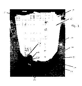
[0011] FIGURE 1 is perspective view of an intermediate bulk
container
with a valve assembly and a multipart collar connector system in accordance
with the present disclosure.
[0012] FIGURE 2 is a fragmentary perspective view of the
system of FIG.
1.
[0013] FIGURE 3 is a rear perspective view of the valve
assembly and
connector of FIG. 1.
[0014] FIGURE 4 is a frontal perspective view of another
exemplary valve
assembly and multipart connector system in accordance with the present
disclosure.
[0015] FIGURE 5 is a side elevation cross-sectional view of
the valve
assembly and multipart connector system of FIG. 4.
[0016] FIGURE 6 is a rear perspective view of the multipart
connector
system and adapter of FIG. 4.
[0017] FIGURE 7 is an end elevation view of the multipart
connector
system and adapter of FIG. 6.
[0018] FIGURE 8 is a side elevation cross-sectional view
along plane A-A
of FIG. 7.
[0019] FIGURE 9 is a rear perspective view of a part of the
multipart
connector system and adapter of FIG. 6.
4
CA 03193573 2023- 3- 22
WO 2022/066889
PCT/US2021/051729
[0020] FIGURE 10 is a rear perspective view of a part of the
multipart
connector system and adapter of FIG. 9 with the outlet of the industrial bulk
container.
[0021] FIGURE 11 is a perspective cross-sectional view of
the multipart
connector system and adapter with the outlet of the industrial bulk container.
[0022] FIGURE 12 is a side elevation cross-sectional view of
the multipart
connector system and adapter with the outlet of the industrial bulk container
of FIG. 11.
[0023] FIGURE 13 is a rear perspective view of the adapter
of FIG. 4.
[0024] FIGURE 14 is a rear elevation view of the adapter of
FIG. 4.
[0025] FIGURE 15 is a side elevation view of separated parts
of the
multipart connector system of FIG. 4.
[0026] FIGURE 16 is a plan view of separated parts of the
multipart
connector system of FIG. 4.
[0027] FIGURE 17 is a perspective view of the valve assembly
of FIG. 3
with a safety seal applied to the handle.
DETAILED DESCRIPTION
[0028] A more complete understanding of the components,
processes
and apparatuses disclosed herein can be obtained by reference to the
accompanying drawings. These figures are merely schematic representations
based on convenience and the ease of demonstrating the present disclosure,
and are therefore not intended to indicate relative size and dimensions of the
devices or components thereof and/or to define or limit the scope of the
exemplary embodiments.
[0029] Although specific terms are used in the following
description for
the sake of clarity, these terms are intended to refer only to the particular
structure of the embodiments selected for illustration in the drawings and are
not intended to define or limit the scope of the disclosure. In the drawings
and
CA 03193573 2023- 3- 22
WO 2022/066889
PCT/US2021/051729
the following description below, it is to be understood that like numeric
designations refer to components of like function.
[0030]
Referring now to Fig. 1, an intermediate bulk container or IBC 10
includes an enclosure or tank 12 mounted on a base illustrated as pallet 14.
The tank 12 defines an interior volume configured to store a quantity of a
liquid. In some embodiments, the tank 12 is configured to hold up to a volume
of about 3 cubic meters (793 US Gal.) although capacities are generally
between 1040 and 1,250 liters (275 and 330 Gal). In some embodiments, and
as illustrated, the tank 12 is substantially cube-shaped.
The IBC 10 also
includes a valve assembly 16 coupled proximate to a lower end 21 of tank 12.
The valve assembly 16 controls the outflow of liquid bulk material stored in
the tank 12. In some embodiments, the IBC 10 is configured for stacking of
multiple units. That is, an upper end 22 of tank 12 is configured to provide
upper engaging surfaces that allow for stacking of another IBC on top of IBC
10, and at least partially mate with the lower engaging surfaces of pallet 14.
For example, the upper end 22 may have a shape that is complementary to
and configured to receive a bottom surface 23 of the pallet 14. The Pallet 14
is a rigid generally planar support structure that supports tank 12 and may
include lower surface features configured to at least partially mate with the
upper end 22 of tank 12 of another IBC. In some embodiments and as
illustrated in FIG. 1, the bottom surface 23 of the pallet 14 may include at
least one projection 25 configured to engage a substantially complementary
recess 27 in the upper end 22.
[0031]
The tank 12 is generally made of a material of sufficient
structural rigidity to support the weight of another fully laden IBC stacked
on
top of tank 12. In some embodiments, the tank 12 is formed from a heavy-
duty plastic material to provide a liquid impermeable enclosure for holding
the
liquid bulk material to be handled. In further embodiments, the tank 12 is
composed of high-density polyethylene. It is to be appreciated that the
material composition is not limiting and that other materials may be
substituted herein, including, for example, composites and metals.
6
CA 03193573 2023- 3- 22
WO 2022/066889
PCT/US2021/051729
[0032] In some embodiments and as illustrated in Fig. 1, the
pallet 14
includes fork receiving channels 29 that are located and shaped to accept
forks
(sometimes referred to as tines) of a forklift or other material handling
device
and provides structural rigidity to provide for the movement and handling of
IBC 10 by the forklift. Alternatively and not illustrated, the IBC 10 may
include
a metal cage or other rigid enclosure that encloses tank 12 and provides the
stacking support and a location for stacking another IBC on top of IBC 10.
[0033] With reference to Figs. 1 and 2, at a lower end 23 of
tank 12,
proximate the pallet 14 is an outlet recess 24 formed in part by complimentary
regions of tank 12 and pallet 14. Recess 24 provides a coupling location for
the valve assembly 16 in order to shroud and protect the valve assembly 16
from damage while in use for storage and during transport. At the lower end
23 of tank 12 is an outlet tube 26 that extends from a depending channel
along the lower surface of tank 12 in order to provide for the complete
drainage
of tank 12. The outlet tube 26 may include sidewalls that are formed by
extensions of the external surface of the tank 12. Alternatively, the outlet
tube
26 may comprise a hole in the tank 12 and an annular flange that is secured
about the hole. The flange extends away from the external surface of the thank
wall to provide sidewalls of the outlet tube 26. The sidewalls of the outlet
tube
26 provide a surface for removably connecting an accessory such as a valve
assembly and/or spout. The outboard end of outlet tube 26 includes a set of
external threads 28 illustrated in Figs. 10 and 12). The external threads 28
are generally used to couple with multipart connector 18 as described in
greater detail below.
[0034] The end-facing surface 30 of outlet tube 26 includes a
ring seat
32 formed as a protruding circular flange. Ring seat 32 is an annular flange
around the outlet of outlet tube 26 to provide a seating region for 0-ring 20.
The ring seat 32 has a generally cylindrical outer wall 34. That is, the
annual
outer wall 34 extends from the outer end-facing surface 30 of the outlet tube
26 and is configured to position a sealing member (0-ring). The 0-ring 20 is
configured to be compressed against the cylindrical outer wall 34 and end-
facing surface 30 when valve assembly 16 is connected to the outlet tube 26
of the tank 12.
7
CA 03193573 2023- 3- 22
WO 2022/066889
PCT/US2021/051729
[0035] As described herein, a valve coupling system includes
a multipart
connector 18 carried on valve assembly 16 to couple valve assembly 16 with
tank 12. An 0-ring seal 20 is compressed between valve assembly 18 and
tank 12 to provide a seal at the connection region. The configuration and
structure of the multipart connector 18 and engaging regions of valve
assembly 16 and tank 12 create a highly functional, complete seal and thus,
mitigate if not eliminate leakage. The structure of the valve coupling system
provides for rapid and ease of assembly onto IBC 10 with reduced error in the
final assembly.
[0036] With reference to Figs. 1-5, the valve assembly 16
includes a
valve body 40 that encompasses a valve gate or ball 44. In the exemplary
embodiment of Fig. 5, the valve assembly 16 is a ball valve and gate 44 is a
ball gate. Alternatively, other forms of valves and valve gates may be used
without departing from the scope of this disclosure. A set of gate seats 46
provide a complimentary surface upon which the outer surface of gate 44 rests,
thereby forming a liquid impermeable barrier through valve body 40 when gate
44 is in the closed position. A handle 42 is connected to a stem 48 such that
rotation of handle 42 also rotates stem 48. Stem 48 passes through a bonnet
56 which closes the opening through which gate 44 is assembled, and the
lower end of stem 48 is connected to gate 44 such that rotation of stem 48
also rotates the gate 44 between an open or closed position. Therefore,
rotation of handle 42 allows for gate 44 to be selectively rotated between an
open or closed position. When in the open position, fluid enters the valve
body
40 and passes through gate 44 before exiting the valve body 40.
[0037] To prevent unintended fluid flow, valve assembly 16
includes a
handle locking button 50 with a depending pin 52 protruding from its lower
surface. When the locking button 50 is depressed against a spring 54, the
depending pin 52 engages handle 42 with stem 48. Handle 42 is configured
to not rotatably engage stem 48 when button 50 is not depressed and
depending pin 52 is not engaged. While depending pin 52 is engaged, handle
42 rotatably locks with stem 48 so that rotation of handle 42 rotates stem 48
in order to shift ball 44 between closed and open positions.
8
CA 03193573 2023- 3- 22
WO 2022/066889
PCT/US2021/051729
[0038] With reference to Figs. 3, and 8-14, located at the
inlet end of
valve body 40 is an inlet adaptor 60 that cooperates in forming a leak
resistant
seal with outlet tube 26 on tank 12. The inlet adaptor 60 is formed with a
generally square or rectangular base plate 62 that abuts with and mounts to
valve body 40. In some embodiments, the base plate 62 mounts to the valve
body 40 via fasteners. Integrally formed with plate 62 is a cylindrical body
64
that protrudes laterally. The cylindrical body 64 terminates in an annular
flange
66 that forms a circular connecting plate. A forward anchoring surface 68 on
flange 66 faces opposing base plate 62. The opposite rear-facing surface of
flange 66 is a sealing surface 70 that engages end surface 30 on outlet tube
26. Protruding laterally around the inlet opening 71 of adaptor 60 is a ring
seat 72. The ring seat 72 is an annular seal positioning wall extending from
the sealing surface 70 and integrally formed with flange 66 as a cylindrical
shape having planar sides that form a seat and engagement surface for 0-ring
seal 20.
[0039] With reference to Figs. 3, 5, 6, 8-12 and 16-17 a
multipart
connector 18 is configured to couple the valve assembly 16 to the outlet tube
26 of tank 12. The multipart connector 18 includes two mating coupling collar
halves 74. Collar halves 74 are generally mirror images, which combine to
form a substantially circular collar used in the coupling of the outlet tube
26
and inlet adaptor 60. The inner surface of collar halves 74 include interior
threads 76 sized and shaped to engage with the external threads 28 on the
outlet tube 26. Extending radially from each end of each collar half 74 is an
elongated clamping tab 78 that substantially extends along the width W of the
collar half. Each clamping tab 78 includes holes 80 configured to align with
the
holes 80 of the opposed collar half 74 and receive a set of four connecting
bolts 82 that join collar halves 74. In some embodiments, each clamping tab
includes at least two holes 80. In some embodiments, the contacting surfaces
of the clamping tabs 78 on one collar half 74 include positioning pegs 84
configured to engage peg seats 86 to aid in aligning each collar half 74. That
is, a mating set of peg seats 86 on the clamping tabs 78 of the other collar
half 74 mate with and engage pegs 84 to positively establish proper alignment
and connection of collar halves 74 and speed assembly.
9
CA 03193573 2023- 3- 22
WO 2022/066889
PCT/US2021/051729
[0040] With reference to Figs. 8-12 The outboard end of
coupling collar
halves 74 may include an annular lip 88. When assembled onto inlet adaptor
60, annular lip 88 protrudes between base plate 62 and connecting flange 66.
The rearward-facing surface 89 of annular lip 88 engages against anchor
surface 68 in order to draw adaptor 60 against end surface 30. The Annular
lip 88 rotates freely around cylindrical body 64 as collar halves are threaded
onto outlet threads 28.
[0041] In some embodiments, the outer surface of the collar
halves 74
is knurled or striated in order to provide a solid friction grip and provide
for
hand assembly of valve assembly 16 onto tank outlet 26. In some
embodiments and with reference to Figs. 15 and 16 extending rearwardly from
one mating set of clamping tabs 78 is an end tab 90. End tab 90 may include
an aperture which provides a connection point for a safety seal 92 (as
illustrated in Fig. 17), which in turn couples with a hole in handle 42. The
safety
seal 92 provides a tamper seal to insure product is not improperly removed
from the IBC 10, as well as may prevent unintended rotation of handle 42.
[0042] With reference to Figs. 8, 11 and 12, the ring seat 72
of inlet
adaptor 60 may have a diameter less than that of ring seat 32 of the outlet
tube 26. In these embodiments, when the valve assembly 16 is mounted on
outlet tube 26 the ring seat 72 is positioned within ring seat 32 of the
outlet
tube. The cross-sectional diameter of the material making up 0-ring 20 is
greater than the protruding width of ring seat 32 on outlet 26 and is greater
than the protruding width of ring seat 72 on inlet adaptor 60. The protruding
width of ring seat 32 on outlet 26 is greater than the protruding width of
ring
seat 72 on inlet adaptor 60. End surface 30 therefore makes positive contact
and fully engages with sealing surface 70 while the ring seat 72 is out of
contact with outlet 26. This provides complete compression and sealing by 0-
ring 20 and a complete sealing engagement between 0-ring 20, end surface
30, and sealing surface 70.
[0043] With reference to Fig. 5, the outlet of valve body 40
may include
outlet adaptor 100 that forms a leak resistant seal with the outlet of the
valve
body 40. The outlet adaptor 100 may be formed with a generally square or
CA 03193573 2023- 3- 22
WO 2022/066889
PCT/US2021/051729
rectangular base plate 102 that abuts with and mounts to valve body 40. The
Outlet adaptor 100 includes a cylindrical body 104 that houses a ball 106
configured to prevent fluid backflow through the adaptor 100. In the event of
fluid backflow, the force exerted by the fluid pushes ball 106 into the inlet
opening of outlet adaptor 100 such that ball 106 covers the inlet opening to
the outlet adaptor and forms a liquid impermeable barrier that prevents fluid
backflow into the valve body 40.
[0044] In some embodiments and with reference to Figs. 4 and
5, a grate
108 within the outlet of the outlet adaptor 100 provides a stop for ball 106,
and prevents the ball 106 from dislodging from the outlet adaptor 100. While
fluid is flowing through the outlet adaptor 100 from the outlet adapter inlet
to
the outlet adaptor outlet, the fluid flow pushes ball 106 into grate 108.
Grate
108 seats ball 106 while still allowing fluid to flow around the outer surface
of
the ball 106 and through the outlet of the outlet adaptor 100. Just as the
ball
106 functions to prevent fluid backflow into the valve body 40, alternatively
an outlet backflow check valve 110 or an alternative check valve 112 may
similarly be located in the cylindrical body 104 and used for similar function
preventing unintended backflow through valve assembly 16.
[0045] With reference to Figs. 2, 4 and 5, the outlet of
outlet adaptor
100 also includes a narrowed cylindrical cap locking region 114 which is
configured to lock a cap 120 over the outlet of adaptor 100. Cap 120 fits over
the outboard end of adaptor 100 and forms a removable closure with a liquid
impermeable barrier at the outlet of outlet adaptor 100. Cap 120 carries a set
of locking levers 124 that, once the cap 120 is seated on the cap locking
region
114, may be pivoted to a closed position. On each of levers 124 is an
eccentric
raised surface that protrudes into cap locking region when pivoted to the
closed
position and seat against adaptor 100. When used in this manner, the locking
levers 124 act as a lever by pushing against a flange on the cap locking
region
114 and simultaneously compress the cap 120 against the cap locking region
114, thereby creating a liquid impermeable barrier. The locking levers 124
also each carry at their free end a locking seal ring 122 which, when locking
levers 124 are in the locked position, allow for the placement a band or seal
126, thereby creating a tamper-evident seal for cap 120. In some
11
CA 03193573 2023- 3- 22
WO 2022/066889
PCT/US2021/051729
embodiments, a lanyard 128 is connected to pallet 14 that run through a hole
in a protrusion of cap 120, thereby preventing accidental loss of the cap 120.
[0046] With reference to Figs. 3-5 the valve assembly 16
includes a set
of body connecting bolts 4 extend through and compress together the inlet
adaptor plate 62 and the outlet adaptor plate 102. Because the valve assembly
16 is positioned between the inlet adaptor plate 62 and the outlet adaptor
plate 102, the resulting compression enhances the seal between the valve
assembly 16 and each of the inlet adaptor 60 and the outlet adaptor 100.
[0047] In use valve assembly 16 is mounted on outlet tube 24
of tank
12. Valve body 40 is oriented in the desired position and joined collar halves
74 are turned until they reach a sealed position. In the sealed position 0-
ring
20 is compressed between outlet tube end surface 30 and facing sealing
surface 70. 0-ring 20 is also compressed between telescopingly received ring
seats 32 and 72. Sealing surface 70 on inlet adaptor 60 is drawn back against
end surface 30 adding to the sealing abutment provided by 0-ring 20.
[0048] Changes and modifications in the specifically
described
embodiments can be carried out without departing from the principles of the
present invention, which is intended to be limited only by the scope of the
appended claims, as interpreted according to the principles of patent law
including the doctrine of equivalents.
[0049] To aid the Patent Office and any readers of this
application and
any resulting patent in interpreting the claims appended hereto, applicants do
not intend any of the appended claims or claim elements to invoke 35 U.S.C.
112(f) unless the words "means for" or "step for" are explicitly used in the
particular claim.
12
CA 03193573 2023- 3- 22