Note: Descriptions are shown in the official language in which they were submitted.
1
DESCRIPTION
Title of the Invention
THRUST FOIL BEARING
Technical Field
[0001]
The present disclosure relates to a thrust foil bearing.
Priority is claimed on Japanese Patent Application No. 2020-159534, filed
September 24, 2020, the content of which is incorporated herein by reference.
Background Art
[0002]
In the related art, as a bearing for a high-speed rotating body, a thrust foil
bearing
that is disposed to face a thrust collar provided on a rotary shaft is known
(refer to, for
example, Patent Document 1 below). In the thrust foil bearing, the bearing
surface
thereof is formed of a flexible foil (thin metal plate) so as to be able to
absorb the
movement (shift in the axial direction and tilt of the thrust collar) of the
rotary shaft
caused by vibrations and impacts, and the thrust foil bearing has a foil
structure under the
bearing surface for flexibly supporting the bearing surface.
[0003]
The thrust foil bearing has a form in which a plurality of top foil pieces and
a
plurality of back foil pieces are arranged in the circumferential direction.
The top foil
piece is supported by the back foil piece, and rotation of the thrust collar
causes a
lubricating fluid to be introduced into a space between the top foil piece and
the thrust
collar. This lubricating fluid forms a wedge-shaped fluid lubricating film
between the
top foil piece and the thrust collar, thereby making the load capacity of the
thrust foil
bearing.
CA 03193679 2023- 3- 23
2
Document of Related Art
Patent Document
[0004]
[Patent Document 1] Japanese Patent No. 6065917
Summary of the Invention
Problems to be Solved by the Invention
[0005]
Incidentally, in the above related art, the back foil having a fixed height is
disposed on an inclined surface formed on a base plate in order to form a
wedge-shaped
gap between the top foil and the thrust collar. Although such an inclined
surface may be
formed by cutting work or the like, it may be difficult to form a desired
fluid lubricating
film unless a certain degree of machining accuracy is ensured.
[0006]
The present disclosure is made in view of the above circumstances, and an
object
thereof is to improve the load capacity of the thrust foil bearing.
Means for Solving the Problems
[0007]
In order to solve the above problems, a thrust foil bearing of an aspect of
the
present disclosure includes: a base plate including an insertion hole through
which a shaft
is inserted, and a supporting surface expanding in a direction orthogonal to
an axial
direction of the insertion hole; a step member placed on the supporting
surface and
formed of a different body from the base plate; and a back foil extending in a
circumferential direction of the insertion hole and in which one part of the
back foil is
supported by the supporting surface and another part of the back foil next to
the one part
in the circumferential direction is supported by the step member.
[0008]
In the aspect of the present disclosure, the step member may be formed in a
stair
CA 03193679 2023- 3- 23
3
shape.
[0009]
In the aspect of the present disclosure, the step member may be formed by a
plurality of shims overlapping each other.
[0010]
In the aspect of the present disclosure, the plurality of shims may include
shims
with different thicknesses.
[0011]
In the aspect of the present disclosure, the plurality of shims may include
shims
with different shift amounts of end surfaces thereof
[0012]
In the aspect of the present disclosure, the plurality of shims may include a
shim
that does not directly support the back foil.
[0013]
In the aspect of the present disclosure, an annular member may be attached to
the
base plate, and the step member may be sandwiched between the base plate and
the
annular member.
Effects of the Invention
[0014]
According to the present disclosure, it is possible to improve the load
capacity of
a thrust foil bearing.
Brief Description of the Drawings
[0015]
FIG. 1 is a side view showing an example of a turbo machine to which a thrust
foil bearing of the present disclosure is applied.
FIG. 2 is a side view showing the thrust foil bearing of the present
disclosure.
FIG. 3 is a plan view showing a thrust foil bearing related to a first
embodiment
CA 03193679 2023- 3- 23
4
of the present disclosure.
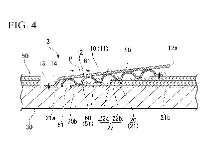
FIG. 4 is a cross-sectional view taken along line A-A and viewed in arrow
direction shown in FIG. 3.
FIG. 5 is a cross-sectional view showing an essential part of a thrust foil
bearing
related to a second embodiment of the present disclosure.
FIG. 6 is an explanatory diagram showing the load capacity of the thrust foil
bearing related to the second embodiment of the present disclosure.
FIG. 7 is a cross-sectional view showing an essential part of a thrust foil
bearing
related to a third embodiment of the present disclosure.
FIG. 8 is a cross-sectional view showing an essential part of a thrust foil
bearing
related to a modification of the present disclosure.
Embodiments for Carrying Out the Invention
[0016]
Hereinafter, thrust foil bearings of the present disclosure will be described
with
reference to the drawings.
[0017]
FIG. 1 is a side view showing an example of a turbo machine to which a thrust
foil bearing of the present disclosure is applied.
In FIG. 1, a reference sign 1 represents a rotary shaft (shaft), a reference
sign 2
represents an impeller provided on an end part of the rotary shaft, and a
reference sign 3
represents a thrust foil bearing related to the present disclosure.
[0018]
A disc-shaped thrust collar 4 is attached to the rotary shaft 1. The thrust
collar 4
is interposed between a pair of thrust foil bearings 3. The impeller 2 is
disposed inside
a housing 5 that is on the stationary side and has a tip clearance 6 between
itself and the
housing 5. The rotary shaft 1 is supported by a radial foil bearing 7.
[0019]
FIG. 2 is a side view showing the thrust foil bearings 3 of the present
disclosure.
CA 03193679 2023- 3- 23
5
As shown in FIG. 2, the two thrust foil bearings 3 are provided on two sides
of
the thrust collar 4 such that the thrust collar 4 is interposed therebetween.
The two
thrust foil bearings 3 have an equal configuration. The thrust foil bearing 3
includes a
top foil 10, a back foil 20, and a base plate 30.
[0020]
A cylindrical bearing spacer 40 (annular member) shown by dashed double-dotted
lines in FIG. 2 is sandwiched between the base plates 30 of the pair of thrust
foil bearings
3. These base plates 30 are connected together through the
bearing spacer 40 by
fastening bolts 41. The outer peripheral portion of the base plate 30 is
provided with
through-holes 42 for inserting the fastening bolts 41 therethrough. One of the
base
plates 30 connected together in this way is in contact with the housing 5 by
fastening
using the fastening bolts 41.
A portion of the housing 5 with which the thrust foil bearing 3 is in contact
is
omitted in FIG. 1.
[0021]
(First Embodiment)
FIG. 3 is a plan view showing the thrust foil bearing 3 related to a first
embodiment of the present disclosure. FIG. 4 is a cross-sectional view taken
along line
A-A and viewed in arrow direction shown in FIG. 3.
As shown in FIG. 3, the base plate 30 includes an insertion hole 30a through
which the rotary shaft 1 is inserted.
[0022]
In the following description, the positional relationships of members may be
described based on the insertion hole 30a. Specifically, the "axial direction"
refers to a
direction in which the insertion hole 30a extends (a direction in which the
rotary shaft 1
is inserted, a direction in which the rotary shaft 1 extends). The "radial
direction" refers
to the radial direction of the insertion hole 30a. The "circumferential
direction" refers
to a circumferential direction along the inner peripheral surface of the
insertion hole 30a.
Alternatively, they may also be referred to as a "radial direction" and a
"circumferential
CA 03193679 2023- 3- 23
6
direction" based on the axis of the rotary shaft 1 inserted through the
insertion hole 30a
and viewed from the axis.
The "radial direction" may also refer to a direction intersecting with the
central
axis line of the insertion hole 30a when viewed in the direction of the
central axis line.
The "circumferential direction" may also refer to a direction around the
central axis line
of the insertion hole 30a.
[0023]
The base plate 30 constitutes the outermost part (the farthest side from the
thrust
collar) of the thrust foil bearing 3 in the axial direction. The base plate 30
is provided
with the insertion hole 30a. That is, the base plate 30 of the present
disclosure is a disk-
shaped member provided with the insertion hole 30a. However, as long as the
base
plate 30 includes the insertion hole 30a, the base plate 30 may be a member
having a
shape (for example, rectangular plate shape) other than a disc shape. It is
not necessary
for the insertion hole 30a to have a strictly cylindrical shape.
[0024]
The base plate 30 is formed of, for example, a metal plate having a thickness
of
several millimeters. The base plate 30 includes a supporting surface 30b (flat
surface)
expanding in a direction orthogonal to the axial direction of the insertion
hole 30a. The
supporting surface 30b is disposed to face the thrust collar 4. The top foil
10, the back
foil 20, and a step member 50 described below are arranged around the
insertion hole 30a
(opening) in the supporting surface 30b. Specifically, the top foil 10 is
supported by the
back foil 20, and the back foil 20 is supported by the base plate 30 and the
step member
50. That is, the top foil 10 is also supported by the base plate
30 and the step member
50 through the back foil 20.
[0025]
In the present disclosure, the top foil 10 and the back foil 20 are formed of
a
plurality (six) of top foil pieces 11 and a plurality (six) of back foil
pieces 21,
respectively. The base plate 30 supports the six top foil pieces 11 and the
six back foil
pieces 21 at regular intervals in the circumferential direction of the
supporting surface
CA 03193679 2023- 3- 23
7
30b. The numbers of the top foil pieces 11 and the back foil pieces 21 are not
limited to
six and may be two to five or seven or more.
[0026]
The top foil 10 of the present disclosure is formed of six thin metal plates
(the top
foil pieces 11) arranged in the circumferential direction. The top foil piece
11 includes
an inclined portion 12 and an attachment portion 13, the inclined portion 12
is inclined
upward (toward a viewer viewing FIG. 3, or in a direction from the base plate
30 toward
the top foil piece 11 in the axial direction) from one side (upstream side in
the rotation
direction of the rotary shaft 1) toward another side (downstream side in the
rotation
direction of the rotary shaft 1) in the circumferential direction, and the
attachment portion
13 is joined to the one side in the circumferential direction of the inclined
portion 12 and
is attached to the base plate 30.
[0027]
As shown in FIG. 3, the inclined portion 12 is formed in an approximately
trapezoidal shape in which the radially inner side and the radially outer side
thereof are
made arc-shaped by cutting out, from a sector shape, the apex side thereof
That is, the
inclined portion 12 includes two edges separated from each other in the
circumferential
direction and extending from the radially inner side to the radially outer
side, a radially
inner-side edge connecting the two edges to each other on the radially inner
side, and a
radially outer-side edge connecting the two edges to each other on the
radially outer side.
The edge (hereinafter referred to as an end part 12a on the other side in the
circumferential direction) of the inclined portion 12 on the other side in the
circumferential direction extending from the radially inner side to the
radially outer side
is made to be a free end.
[0028]
On the other hand, the edge of the inclined portion 12 on the one side in the
circumferential direction extending from the radially inner side to the
radially outer side
is connected to the attachment portion 13 through a bent portion 14. As shown
in FIG.
4, the bent portion 14 is configured of a first bend and a second bend
positioned on the
CA 03193679 2023- 3- 23
8
other side in the circumferential direction of the first bend. The first bend
bends toward
the back side of a surface of the top foil piece 11 facing the base plate 30.
The second
bend bends toward the surface of the top foil piece 11 facing the base plate
30. That is,
the bent portion 14 has a stair shape. Both of the first bend and the second
bend have
obtuse angles.
In other words, the first bend bends to be convex toward the base plate 30,
and
the second bend bends to be convex toward the opposite side from the base
plate 30
(toward the thrust collar 4).
[0029]
The inclined portion 12 positioned to be closer to the other side in the
circumferential direction than the bent portion 14 is supported by a
supporting portion 22
of the back foil piece 21. The inclined portion 12 supported by the supporting
portion
22 is disposed to be inclined at an initial inclination angle so as to
gradually separate
from the base plate 30 from the one side to the other side in the
circumferential direction.
The initial inclination angle means the inclination angle of the top foil
piece 11 (that is,
the inclined portion 12) with respect to the base plate 30 when the load is
zero. The
base plate 30 of the present disclosure includes the supporting surface 30b
expanding in a
direction orthogonal to the axial direction, and the inclined portion 12 is
inclined with
respect to the supporting surface 30b.
[0030]
The attachment portion 13 is connected to the one side (first bend-side) in
the
circumferential direction of the bent portion 14. In the present disclosure,
the
attachment portion 13 is formed in a strip shape having the same length as
that of the
bent portion 14 in the radial direction and is spot-welded to the base plate
30. That is,
this welding position is the attachment position of the top foil piece 11 to
the base plate
30. The attachment of the top foil piece 11 to the base plate 30
can also be performed
by, for example, screwing instead of spot-welding. The attachment portion 13
and the
bent portion 14 do not have to have an equal length in the radial direction.
[0031]
CA 03193679 2023- 3- 23
9
On the other hand, the back foil 20 is formed of six thin metal plates (the
back
foil pieces 21) arranged in the circumferential direction. The back foil piece
21 includes
the supporting portion 22 supporting the inclined portion 12 of the top foil
piece 11. As
shown in FIG. 4, the supporting portion 22 is a wave-shaped foil (bump foil)
in which
mountain parts 22a and valley parts 22b are alternately formed. The supporting
portion
22 elastically supports the inclined portion 12 of the top foil piece 11.
[0032]
For the supporting portion 22, for example, a bump foil, a spring foil shown
in
Japanese Unexamined Patent Application, First Publication No. 2006-57652 or
Japanese
Unexamined Patent Application, First Publication No. 2004-270904, a back foil
shown in
Japanese Unexamined Patent Application, First Publication No. 2009-299748, or
the like
can be used. Although the spring foils shown in Japanese Unexamined Patent
Application, First Publication No. 2006-57652 and Japanese Unexamined Patent
Application, First Publication No. 2004-270904, and the back foil shown in
Japanese
Unexamined Patent Application, First Publication No. 2009-299748 are foils
used for
radial bearings, when the foils are opened to be flat and are formed in an
annular shape,
they can be foils (the supporting portion 22) used for the thrust foil bearing
3.
[0033]
The supporting portion 22 of the present disclosure is formed of a bump foil.
The supporting portion 22 is formed to be slightly smaller than the inclined
portion 12 of
the top foil piece 11 in plan view shown in FIG. 3. Therefore, the supporting
portion 22
is covered by the inclined portion 12. The supporting portion 22 is formed,
similarly to
the inclined portion 12, in an approximately trapezoidal shape in which the
radially inner
side and the radially outer side thereof are made arc-shaped by cutting out,
from a sector
shape, the apex side thereof That is, the supporting portion 22 includes two
edges
separated from each other in the circumferential direction and extending from
the radially
inner side to the radially outer side, a radially inner-side edge connecting
the two edges
to each other on the radially inner side, and a radially outer-side edge
connecting the two
edges to each other on the radially outer side.
CA 03193679 2023- 3- 23
10
[0034]
The edge (hereinafter referred to as an end part on the one side in the
circumferential direction) of the supporting portion 22 on the one side in the
circumferential direction extending from the radially inner side to the
radially outer side
is provided with a parallel part (hereinafter referred to as a back foil end
21a) extending
to be parallel to the edge (hereinafter referred to as an end part on the
other side in the
circumferential direction) of the supporting portion 22 on the other side in
the
circumferential direction extending from the radially inner side to the
radially outer side.
In the supporting portion 22, the valley parts 22b and the mountain parts 22a
are
alternately joined together in a first direction from the back foil end 21a
toward the end
part of the supporting portion 22 on the other side in the circumferential
direction, that is,
in a normal direction (also referred to as a direction orthogonal to the ridge
lines of the
mountain parts 22a) orthogonal to the back foil end 21a and the end part of
the
supporting portion 22 on the other side in the circumferential direction.
[0035]
As shown in FIG. 4, the valley part 22b includes a flat surface and faces the
base
plate 30 and the step member 50. The mountain part 22a is made to be an arch-
shaped
part connecting adjacent valley parts 22b to each other. The back foil piece
21 is
supported by the base plate 30 and the step member 50. Therefore, the valley
parts 22b
can come into contact with the base plate 30 and the step member 50. Two end
parts of
the supporting portion 22, that is, the back foil end 21a and the end part
(hereinafter
referred to as an attachment portion 21b) of the supporting portion 22 on the
other side in
the circumferential direction, are formed of the valley parts 22b.
[0036]
In the present disclosure, the valley parts 22b are formed with approximately
equal pitches, and the mountain parts 22a are formed with approximately equal
pitches.
The heights of the mountain parts 22a are formed to be a fixed height. The
attachment
portion 21b is spot-welded to the step member 50. That is, this welding
position is the
attachment position of the back foil piece 21 in the circumferential
direction. That is, in
CA 03193679 2023- 3- 23
11
the present disclosure, the attachment position of the back foil piece 21 is
in the valley
part 22b (the attachment portion 21b) positioned at the end on the other side
(right side in
FIG. 4) in the first direction.
[0037]
The valley part 22b (the back foil end 21a) positioned at an end of the back
foil
piece 21 on the one side (left side in FIG. 4) in the first direction is made
to be a free end.
That is, when a load acts on the back foil piece 21, the back foil end 21a can
move
toward the one side in the first direction. The attachment of the back foil
piece 21 to the
step member 50 can also be performed by, for example, screwing instead of spot-
welding.
[0038]
The step member 50 is formed of a different body from the base plate 30 and is
placed on the supporting surface 30b. As shown in FIG. 3, the step member 50
includes
a step support portion 51 supporting the back foil piece 21 (the back foil 20)
from an
intermediate position in the circumferential direction, an extending portion
52 joined to
the other side in the circumferential direction of the step support portion 51
and
extending outward in the radial direction, and a sandwiched portion 53 joined
to the
extending portion 52 on an outer side than the step support portion 51 in the
radial
direction and extending toward the one side in the circumferential direction.
[0039]
The extending portion 52 is connected to the outer side in the radial
direction of
the other side in the circumferential direction of the step support portion
51. The
extending portion 52 is formed in a strip shape extending outward in the
radial direction
and is connected to the sandwiched portion 53.
The sandwiched portion 53 is formed in an approximately trapezoidal shape in
which the radially inner side and the radially outer side thereof are made arc-
shaped by
cutting out, from a sector shape, the apex side thereof. That is, the
sandwiched portion
53 includes two edges separated from each other in the circumferential
direction and
extending from the radially inner side to the radially outer side, a radially
inner-side edge
CA 03193679 2023- 3- 23
12
connecting the two edges to each other on the radially inner side, and a
radially outer-
side edge connecting the two edges to each other on the radially outer side.
[0040]
A slit 54 is formed between the sandwiched portion 53 and the step support
portion 51. The slit 54 divides the step member 50 into an inner area and an
outer area
in the radial direction. The slit 54 extends in the circumferential direction
from an edge
on the one side toward another edge on the other side in the circumferential
direction of
the step member 50. As shown in FIG. 3, the outer area than the slit 54
extends to a
position in the radial direction in which the bearing spacer 40 is disposed.
That is, the
sandwiched portion 53 is sandwiched between the base plate 30 and the bearing
spacer
40 in the axial direction.
[0041]
The sandwiched portion 53 is provided with a through-hole 55 through which the
fastening bolt 41 that attaches the bearing spacer 40 to the base plate 30 is
inserted. The
through-hole 55 of the sandwiched portion 53 overlaps the through-hole 42 of
the base
plate 30 in the axial direction. The through-hole 55 of the sandwiched portion
53 is
disposed in the vicinity of the connecting position to the extending portion
52. As
shown in FIG. 3, the length of the sandwiched portion 53 in the radial
direction may be
equivalent to the length in the radial direction from the inner peripheral
surface to the
outer peripheral surface of the bearing spacer 40. The sandwiched portion 53
may have
a length in the circumferential direction corresponding to about 60 (about
1/6 of the
entire circumference) of the 360 circumference of the bearing spacer 40.
Thereby, the
six step members 50 (the sandwiched portions 53) are sandwiched on
approximately the
entire circumference of the bearing spacer 40.
[0042]
As shown in FIG. 4, the step member 50 is formed by a plurality of shims 60
(thin
metal plates) overlapping each other. The plurality of shims 60 are each
formed in a
plate shape having a fixed thickness. The plurality of shims 60 overlap each
other in the
step support portion 51 such that end surfaces 61 thereof on the one side in
the
CA 03193679 2023- 3- 23
13
circumferential direction further shift to the other side in the
circumferential direction as
the number of stages increases. That is, the end surface 61 of the shim 60 on
the second
stage shifts by a certain distance to the other side in the circumferential
direction from the
end surface 61 of the shim 60 on the first stage. The same goes for the end
surface 61
of the shim 60 on each of the third and subsequent stages. In the plurality of
shims 60,
the end surfaces of the portions (in each of the extending portion 52 and the
sandwiched
portion 53 described above) other than the step support portion 51 are
aligned.
That is, in the plurality of shims 60, the positions in a direction along the
supporting surface 30b of the end surfaces of the portions (in each of the
extending
portion 52 and the sandwiched portion 53 described above) other than the step
support
portion 51 are the same as each other.
[0043]
The shift amounts P between the end surfaces 61 of the overlapping shims 60
(for
example, the shim 60 on the first stage and the shim 60 on the second stage)
are a fixed
amount. The shift amounts P are the same as the pitches of the mountain parts
22a and
the pitches of the valley parts 22b of the back foil piece 21. The number of
the shims
60 is equal to the number of the mountain parts 22a. The number of the shims
60 is one
less than the number of the valley parts 22b. The plurality of shims 60 (the
step support
portion 51) support the valley parts 22b other than the valley part 22b
positioned to be
closest to the one side in the circumferential direction. That is, the valley
part 22b (one
part) positioned to be closest to the one side in the circumferential
direction is supported
by the supporting surface 30b of the base plate 30, and the other valley parts
22b (the
remainder) are supported by the stages of the step support portion 51 one by
one.
[0044]
Next, the operation of the thrust foil bearing 3 having the above
configuration
will be described.
As shown in FIG. 2, the thrust foil bearings 3 are provided on both sides of
the
thrust collar 4 so that the thrust collar 4 is interposed therebetween.
Therefore, the
movement of the rotary shaft 1 in two different directions parallel to the
thrust direction
CA 03193679 2023- 3- 23
14
thereof can be limited.
[0045]
In such a state, when the rotary shaft 1 rotates so that the thrust collar 4
starts
rotating, while the thrust collar 4 and the top foil piece 11 rub against each
other, an
ambient fluid is pushed into a wedge-shaped space formed therebetween. Then,
when
the rotational speed of the thrust collar 4 reaches a certain speed, a fluid
lubrication film
is formed therebetween. The pressure of the fluid lubrication film pushes the
top foil
piece 11 toward the back foil piece 21, and the thrust collar 4 breaks away
from the
contact state with the top foil piece 11 and starts rotating in non-contact.
[0046]
As shown in FIG. 4, one part of the back foil piece 21 is supported by the
supporting surface 30b, and the remainder thereof is supported by the step
member 50
from an intermediate position in the circumferential direction. The supporting
surface
30b is a flat surface expanding in a direction orthogonal to the axial
direction of the
insertion hole 30a. The step member 50 is placed on the supporting surface 30b
and is
formed in a stair shape whose height increases toward the other side in the
circumferential direction. That is, the step member 50 of this embodiment is
provided
with a plurality of surfaces that are approximately parallel to the supporting
surface 30b
and have different heights. Since the step member 50 is a different body from
the base
plate 30, machining can be high accurately performed thereon, and a pseudo-
inclined
surface with high accuracy can be formed on the supporting surface 30b.
Thereby, an
appropriate inclination can be provided in the back foil piece 21, and a
proper fluid
lubricating film can be formed between the thrust collar 4 and the top foil
piece 11.
[0047]
Therefore, according to the first embodiment described above, a configuration
is
adopted, which includes the base plate 30 including the insertion hole 30a
through which
the rotary shaft 1 is inserted and the supporting surface 30b expanding in a
direction
orthogonal to the axial direction of the insertion hole, the step member 50
placed on the
supporting surface 30b and formed of a different body from the base plate 30,
and the
CA 03193679 2023- 3- 23
15
back foil 20 extending in the circumferential direction of the insertion hole
30a and in
which one part of the back foil 20 is supported by the supporting surface 30b
and the
remainder of the back foil 20 is supported by the step member 50 from an
intermediate
position in the circumferential direction, whereby it is possible to improve
the load
capacity of the thrust foil bearing 3.
In other words, as shown in FIG. 4, in the back foil piece 21, one part
thereof is
supported by the supporting surface 30b, and another part thereof next to the
one part in
the circumferential direction is supported by the step member 50. The back
foil piece
21 may include a portion that is not supported by the supporting surface 30b
or the step
member 50.
[0048]
In the first embodiment, since the step member 50 is formed in a stair shape,
it is
possible to form a pseudo-inclined surface with a simple shape and high
accuracy.
[0049]
In the first embodiment, the step member 50 is formed by the plurality of
shims
60 overlapping each other. The shim 60 can be high accurately mass-
manufactured
through etching, precision press working or the like.
[0050]
In the first embodiment, as shown in FIG. 3, the bearing spacer 40 is attached
to
the base plate 30, and the step member 50 is sandwiched between the base plate
30 and
the bearing spacer 40. Thereby, the step member 50 can be sandwiched by using
the
bearing spacer 40 that secures a space between the base plates 30 of the pair
of thrust foil
bearings 3. The step member 50 is sandwiched, whereby the step member 50 is
limited
from moving from its predetermined position.
[0051]
(Second Embodiment)
Next, a second embodiment of the present disclosure will be described. In the
following description, the same or equivalent components as or to those of the
above-
described embodiment will be represented by equal reference signs, and the
descriptions
CA 03193679 2023- 3- 23
16
thereof will be simplified or omitted.
[0052]
FIG. 5 is a cross-sectional view showing an essential part of a thrust foil
bearing 3
related to the second embodiment of the present disclosure. FIG. 5 corresponds
to a
cross-sectional view taken along line A-A and viewed in arrow direction shown
in FIG.
3.
As shown in FIG. 5, the second embodiment differs from the above embodiment
in that a step member 50 (a plurality of shims 60) includes shims 60 with
different
thicknesses.
[0053]
Specifically, the shim 60 on the first stage is formed with a thickness tl .
The
shim 60 on the second stage is formed with a thickness t2 that is greater than
the
thickness tl . The shim 60 on the third stage is formed with a thickness t3
that is less
than the thickness t2. The shim 60 on the fourth stage is formed with a
thickness t4 that
is less than the thickness t3. The shim 60 on the fifth stage is formed with a
thickness t5
that is slightly less than the thickness t4.
[0054]
That is, the shim 60 on the second stage is the thickest, and the thicknesses
of the
shims 60 decrease away from the shim 60 on the second stage toward each of one
side
(upper side in FIG. 5, the thrust collar 4-side) and another side (lower side
in FIG. 5, the
base plate 30-side) in the axial direction. The back foil piece 21 is
supported by the
plurality of shims 60 (a step support portion 51) having such thicknesses. The
top foil
piece 11 supported by the back foil piece 21 includes an inclined portion 12A
that curves
to be convex toward the one side in the axial direction. The inclined portion
12A curves
such that the inclination thereof with respect to the supporting surface 30b
(in other
words, the thrust collar 4) gradually decreases toward the other side in the
circumferential direction.
[0055]
FIG. 6 is an explanatory diagram showing the load capacity of the thrust foil
CA 03193679 2023- 3- 23
17
bearing 3 related to the second embodiment of the present disclosure. In the
graph
shown in FIG. 6, a horizontal axis x refers to the position in the
circumferential direction,
and a vertical axis P(x) refers to the pressure of the fluid lubrication film,
that is, the load
capacity of the thrust foil bearing 3.
As shown in FIG. 6, in the second embodiment, the top foil piece 11 includes
the
inclined portion 12A with a curved surface, so the pressure of the fluid
lubrication film
increases by the value corresponding to the meshed area when compared with the
inclined portion 12 with the inclined surface (surface having a fixed
inclination angle) of
the first embodiment.
That is, according to the second embodiment, as shown in FIG. 5, the load
capacity of the thrust foil bearing 3 can be improved by making the
thicknesses of the
plurality of shims 60 different.
[0056]
(Third Embodiment)
Next, a third embodiment of the present disclosure will be described. In the
following description, the same or equivalent components as or to those of the
above-
described embodiments will be represented by equal reference signs, and the
descriptions
thereof will be simplified or omitted.
[0057]
FIG. 7 is a cross-sectional view showing an essential part of a thrust foil
bearing 3
related to the third embodiment of the present disclosure. FIG. 7 corresponds
to a cross-
sectional view taken along line A-A and viewed in arrow direction shown in
FIG. 3.
As shown in FIG. 7, the third embodiment differs from the above embodiments in
that a step member 50 (a plurality of shims 60) includes shims 60 with
different shift
amounts of end surfaces 61. The thicknesses of the plurality of shims 60 are a
fixed
value, but the thicknesses may be different.
[0058]
Specifically, the shim 60 on the second stage overlaps the shim 60 on the
first
stage such that the end surface 61 shifts by a shift amount P1 therefrom. The
shim 60
CA 03193679 2023- 3- 23
18
on the third stage overlaps the shim 60 on the second stage such that the end
surface 61
shifts therefrom by a shift amount P2 that is less than the shift amount P1.
The shim 60
on the fourth stage overlaps the shim 60 on the third stage such that the end
surface 61
shifts therefrom by a shift amount P3 that is greater than the shift amount
P2. The shim
60 on the fifth stage overlaps the shim 60 on the fourth stage such that the
end surface 61
shifts therefrom by a shift amount P4 that is greater than the shift amount
P3.
[0059]
That is, the shift amount P2 of the shim 60 on the third stage is the smallest
(the
supporting area of the shim 60 on the second stage is the smallest), and the
supporting
areas of the shims 60 increase away from the shim 60 on the second stage
toward each of
one side (upper side in FIG. 5) and another side (lower side in FIG. 5) in the
axial
direction. The back foil piece 21 is supported by the plurality of shims 60 (a
step
support portion 51) having the above configuration. The top foil piece 11
supported by
the back foil piece 21 forms an inclined portion 12B that curves to be convex
toward the
one side in the axial direction. Thereby, the load capacity of the thrust foil
bearing 3
can be improved similarly to the second embodiment.
The above supporting area refers to the area of a region of each shim 60
exposed
toward the back foil 20.
[0060]
In the third embodiment, the shim 60 on the second stage does not directly
support the valley part 22b of the back foil piece 21, and the shim 60 on the
fourth stage
supports two valley parts 22b. Thereby, the shape of the inclined portion 12B
of the top
foil piece 11 is not formed to have only a simple curved surface represented
by a
quadratic function but can also be formed to have a curved surface represented
by a cubic
function. In the example shown in FIG. 7, the other side in the
circumferential direction
of the inclined portion 12B curves so as to warp toward the one side in the
axial
direction. Thereby, the load capacity of the top foil piece 11 on the other
side in the
circumferential direction can be improved.
That is, part of the inclined portion 12B on the one side in the
circumferential
CA 03193679 2023- 3- 23
19
direction curves so as to be convex toward the one side in the axial
direction, and part of
the inclined portion 12B on the other side in the circumferential direction
curves so as to
be convex toward the other side in the axial direction, so in FIG. 7, the
inclined portion
12B curves in an inverted S shape.
The shim 60 on the second stage is not in contact with the valley part 22b of
the
back foil piece 21.
[0061]
Hereinbefore, the appropriate embodiments of the present disclosure have been
described with reference to the drawings, but the present disclosure is not
limited to the
above embodiments. The various shapes, combinations and the like of the
components
shown in the above-described embodiments are examples, and various
modifications can
be adopted based on design requirements and the like within the scope of the
present
disclosure.
[0062]
For example, as in a modification shown in FIG. 8, the step member 50 may not
be formed of the plurality of shims 60. The step member 50 of this
modification
includes a plurality of steps 70 that are integrally formed through etching,
precision press
working or the like, and the plurality of steps 70 form a step support portion
51.
[0063]
For example, in the above embodiments, the step member 50 is sandwiched
between the base plate 30 and the bearing spacer 40, but the step member 50
may be
fixed to the base plate 30 by welding, bolt fastening or the like.
Industrial Applicability
[0064]
The present disclosure is applicable to a thrust foil bearing including a base
plate
and a back foil supported by the base plate, and an object thereof is to
improve the load
capacity of the thrust foil bearing.
CA 03193679 2023- 3- 23
20
Description of Reference Signs
[0065]
1 rotary shaft
2 impeller
3 thrust foil bearing
4 thrust collar
5 housing
6 tip clearance
7 radial foil bearing
10 top foil
11 top foil piece
12 inclined portion
12a end part
12A inclined portion
12B inclined portion
13 attachment portion
14 bent portion
back foil
21 back foil piece
20 21a back foil end
21b attachment portion
22 supporting portion
22a mountain part
22b valley part
30 base plate
30a insertion hole
30b supporting surface
40 bearing spacer
41 fastening bolt
CA 03193679 2023- 3- 23
21
42 through-hole
50 step member
51 step support portion
52 extending portion
53 sandwiched portion
54 slit
55 through-hole
60 shim
61 end surface
70 step
P shift amount
CA 03193679 2023- 3- 23