Note: Descriptions are shown in the official language in which they were submitted.
CA 03194170 2023-03-06
WO 2022/074555
PCT/IB2021/059121
1
Lance for blowing oxygen in steelmaking
[001] The invention is related to a lance for blowing oxygen onto a bath of
molten steel,
and more particularly to a lance for post-combustion in steelmaking.
[002] In steel-refining, the main starting materials are usually a mixture of
liquid pig-iron
and scrap. The quantity of scrap which can be added, i.e. the scrap addition
or scrap rate,
depends notably on the temperature of the liquid pig iron and on the quantity
of heat
io generated in the converter by oxidation of chemical elements. Most of it
concerns the
transformation of carbon into carbon monoxide CO and then into dioxide 002.
The more
CO2 is formed, the more heat is created and may be transferred to bath so as
to provide
energy for additional scrap melting. The transformation of CO to CO2 is known
as post-
combustion.
[003] Typically, with usual single oxygen flow, very little CO is post-
combusted into CO2
inside the vessel. By injecting a secondary flow of oxygen during the process,
the unburned
CO moving upward meets additional 02 provided by this secondary flow and is
then
combusted into 002. The reaction is defined by the commonly known equation: CO
+ Y202
= 002.
[004] There are two different technologies which have been developed to
provide the
secondary flow of oxygen. The first one consists in having a single oxygen
flow supply and
then split it in a primary flux for standard decarburization and a secondary
flow for enhancing
post-combustion.
[005] This first technology has the advantage of requiring few modifications
of existing
lances and for example to keep same lance diameter and weight, thus not
impairing the
overall support structure of the lance and reducing investment costs.
Disadvantage is that
the secondary flow rate of oxygen being defined by the surface ratio between
primary and
secondary oxygen ejection means, it cannot be managed independently form the
primary
flow according to the process phases. Also, if oxygen supply is limited,
primary oxygen flow
is reduced, which impairs the decarburization process and productivity.
CA 03194170 2023-03-06
WO 2022/074555
PCT/IB2021/059121
2
[006] The second technology consists in having a double flow lances, wherein
primary
and secondary flows of oxygen have their own supply and are independently
controlled. An
example of a lance according to this technology is illustrated in patent US
5,681,526. Main
advantage of this technology is that primary and secondary flows of oxygen are
independently controlled which allows to more accurately control the post-
combustion
process and thus to increase the post-combustion rate. Disadvantage of this
technology is
that it requires an overall change on the installation and thus high
investment cost.
[007] There is so a need for a lance allowing to perform a controlled post-
combustion
which can be easily implemented on existing installation and with a reduced
investment
io cost.
[008] This problem is solved by a lance according to the invention, this lance
having an
upper and a lower part and comprising a main tube for the supply of a primary
flux of
oxygen, a second tube surrounding the main tube to form a first annular gap
for the
circulation of cooling water within the lance, a third tube surrounding the
second tube to
form a second annular gap for the supply of a secondary flux of oxygen and
extending only
along the upper part of the lance, a fourth tube comprising a first part
surrounding the third
tube along the upper part of the lance and the second part surrounding the
second tube
along the lower part of the lance to form a third annular gap for circulation
of cooling water
within the lance, a tip, located at the end of the lower part of the lance,
provided with at
least one primary oxygen ejection mean for blowing the primary flux of oxygen
which is
designed to be in fluid connexion with both first and third annular gaps to
insure circulation
of water within the lance, and a distributor making the junction between the
upper and the
lower part of the lance, said distributor being provided with at least one
secondary oxygen
ejection mean in fluid connexion with the third gap for blowing the secondary
flux of oxygen,
the secondary oxygen ejection means being located at distance d above the
primary oxygen
ejection mean such as the ratio between the distance d and the internal
diameter D of the
converter is from 0,04 to 0,15.
[009] The method of the invention may also comprise the following optional
characteristics
considered separately or according to all possible technical combinations:
- the ratio between the distance d and the internal diameter D of the
converter 2 is
from 0,08 to 0,15
- secondary oxygen ejection means of the distributor are located between 150
and
750 mm above the primary oxygen ejection means of the tip,
CA 03194170 2023-03-06
WO 2022/074555
PCT/IB2021/059121
3
- the distributor is provided with sealing means preventing leakage of
water,
- the distributor is mounted slidable around the fourth tube of the lance,
- the tip comprises at least four primary oxygen ejection means,
- the primary oxygen ejection means have a diameter comprised from 40 to
50mm,
- the primary oxygen ejection means have a diameter comprised from 40 to 45mm,
- the primary oxygen ejection means are designed so as to eject the primary
flux of
oxygen with an ejection angle a with the central axis Z of the lance from 10
to 20 ,
- the primary oxygen ejection means are designed so as to eject the primary
flux of
oxygen with an ejection angle a with the central axis Z of the lance from 14
to 18 ,
- the secondary oxygen ejection means have an oblong shape,
- the biggest width of the secondary oxygen ejection means is from 10 to
25mm,
- the first annular gap 31 allows the entry of water into the lance and the
third annular
gap allows the exit of water from the lance.
[0010] The invention is also related to a steelmaking method using a lance
according to
anyone of the previous embodiments.
[0011] Other characteristics and advantages of the invention will emerge
clearly from the
description of it that is given below by way of an indication and which is in
no way restrictive,
with reference to the appended figures in which:
Figure 1 illustrates a post-combustion method in a converter
Figure 2 illustrates a post-combustion lance according to an embodiment of the
invention
[0012] Elements in the figures are illustration and may not have been drawn to
scale.
[0013] Figure 1 illustrates a converter 2 containing a bath of molten metal
20. The converter
2 is internally covered with a wall of refractories 3 and has a dimeter D. The
molten metal
is pig iron which needs to be decarburized to produce steel. To perform such a
decarburization, a lance 1 is inserted into the converter and blows a primary
flux of oxygen
21 towards the molten metal 20 through an ejection mean provided in the tip 15
of the lance.
This decarburization allows to remove carbon from the bath as CO. In order to
combust the
unburned CO on the slag layer into 002, a secondary flux of oxygen 22 is
injected towards
the bath. This reaction is exothermic and releases a lot of energy which can
be further used
to melt scrap into the molten bath.
CA 03194170 2023-03-06
WO 2022/074555
PCT/IB2021/059121
4
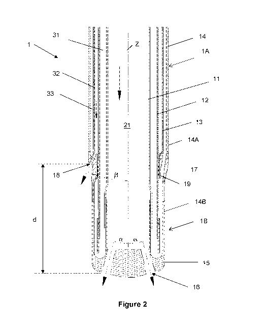
[0014] This double oxygen ejection is performed with a post combustion lance,
as the one
illustrated in figure 2, according to one embodiment of the invention. As a
purpose of
information, such a lance is usually more than 20 meters long. The post-
combustion lance
1 according to the invention comprises a plurality of tubes which surround one
another and
are concentric to a central longitudinal axis of the lance Z. The lance
according to the
invention is made of an upper part 1A and of a lower part 1B joined together
by a distributor
17. The lower part 1B of the lance is the one closest to the bath 20 when
inserted into the
steelmaking vessel 2. The lance is composed of a first tube 11 which supplies
the primary
flux of oxygen 21, a second tube 12, which surrounds the main tube 11 thus
forming a first
io annular gap 31 for the supply of cooling water within the lance 1. The
lance being subjected
to high temperature within the steelmaking process it needs to be constantly
cooled down
so as to avoid being quickly damaged. Those two first tubes go along the whole
length of
the lance, each in a single part, which allows reducing risks of tightness
issues. The first
tube 11 is preferentially made of a material allowing the passage of a flow at
a speed of at
least 60m/s, such as stainless steel.
[0015] The lance 1 then comprises a third tube 13, surrounding the second tube
12 to form
a second annular gap 32 for the supply of the secondary flux of oxygen 22
necessary for
the post-combustion. This third tube does not extend all along the length of
the lance 1 but
only along the upper part 1A. This third tube is preferentially designed so
that there is a ratio
of 1/5 between the section of the gap for the circulation of the primary of
oxygen and the
section of the gap for the circulation of the secondary flux of oxygen. The
lance comprises
than a fourth tube 14, comprising a first part 14A, which surrounds the third
tube 13 along
the upper part 1A of the lance, and a second part 14B surrounding the second
tube 12 along
the lower part 1B of the lance. This fourth tube 14 thus form a third annular
gap 33 allowing
to draw off the cooling water. In another embodiment, the first annular gap 31
may be
designed to drawn off the cooling water from the lance 1 while the third
annular gap 33
allows the entry of the water within the lance 1.
[0016] The lance 1 further comprises a tip 15, closing the lower part of the
lance 1B. This
tip is in fluid connexion with both first and third annular gaps so as to
close the water circuit
and provide circulation of water within the lance. This furthermore allows the
cooling down
of the tip 15 itself which is the closest part to the molten steel and thus
subjected to the
highest temperatures. The tip is provided with at least one primary oxygen
ejection mean
16 for blowing primary flow of oxygen 21 onto the bath of molten steel and
allowing
decarburization. In a preferred embodiment the tip is provided with at least
four primary
CA 03194170 2023-03-06
WO 2022/074555
PCT/IB2021/059121
oxygen ejection means 16, the optimal number depending notably of the size of
the ladle
and thus of the circumference of the molten bath. The diameter of the primary
oxygen
ejection means depends on the same parameters. In a preferred embodiment,
those
primary oxygen ejection means 16 have a diameter comprised between 40 and
50mm,
5 preferentially between 40 and 45mm. In a preferred embodiment these
ejection means are
designed so as to eject the primary flux of oxygen with an ejection angle a
with the central
axis Z of the lance 1 comprised between 10 and 20 , preferentially between 14
and 18 .
This allows to find the good compromise between maximisation of the surface of
the molten
bath receiving oxygen ang keeping sufficient distance from the refractories
walls to avoid
io damaging them.
[0017] The lance is designed to receive a distributor 17 making the junction
between the
upper 1A and the lower part 1B of the lance and ensuring the circulation of
water between
the upper 14A and the lower 14B parts of the fourth tube. This distributor 17
is provided with
at least one secondary oxygen ejection mean 18 in fluid connexion with the
third tube 13
for blowing the secondary flux of oxygen 22 onto the bath of molten steel.
This secondary
flux of oxygen will provide necessary fuel for the further combustion of CO
and the release
of additional energy for scrap melting. In a preferred embodiment the
distributor 17 is
provided with the same number of secondary ejection means 18 as the number of
primary
ejection means 16 provided on the tip 15. These ejection means 18 may have
exits with a
diameter comprised between 10 and 25mm. Said exits may have an oblong or
circular
shape. Secondary oxygen ejection means 18 are located at a distance d above
the primary
oxygen ejection means 16 of the tip 15 such as the ratio (d/D) between the
distance d and
the internal diameter D of the converter 2 is from 0,04 to 0,15,
preferentially from 0,08 to
0,15. They may be located between 500 and 750mm above the first oxygen
ejection means
16 of the tip 15. This distance d between both ejection means allow to enhance
the
efficiency of the secondary flux of oxygen by promoting the mixing of CO and
02 into the
bath.
[0018] In a most preferred embodiment the distributor is mounted on the lance
1 so as to
be able to slide of few centimetres, less than 5 cm, along the pipe 12 in
order to follow the
thermal expansion of the external tube 14 due to thermal constraints it is
subjected to. This
is done by appropriate means, such as 0-rings 19. The distributor is
furthermore provided
with sealing means preventing water leakage in the annular gaps supplying the
oxygen
flows. These sealing means are for example 0-rings.
CA 03194170 2023-03-06
WO 2022/074555 PCT/IB2021/059121
6
[0019] With the lance according to the invention it is possible to insert the
third tube 13
within the others and thus the external diameter of the lance is not increased
compared to
existing lance and there is thus no need to replace the overall supporting
structure of the
lance which reduce investment costs for the post-combustion process. Moreover,
the
secondary flux of oxygen crosses only once the water circulation channels,
which allows to
limit the water pressure losses compared to prior art combustion lances.
Finally, with the
lance according to the invention, risks of tightness issues are limited.