Note: Descriptions are shown in the official language in which they were submitted.
WO 2022/076337
PCT/US2021/053458
DELIVERY DEVICE WITH CAM DRIVEN PERISTALTIC PUMP
This application claims priority to U.S. Provisional Patent Application No.
63/089.922
filed on October 9, 2020, which is hereby incorporated by reference in its
entirety.
Field of the Invention
[00011 The present invention relates to medical devices, and more
particularly, to a medicament
delivery device with at least one fluid channel to direct the medicament, such
as insulin, to a
delivery mechanism for delivering the medicament to a patient. The delivery
device includes a
cam driven peristaltic pump mechanism.
Background of the invention
(00021 Diabetes is a group of diseases characterized by high levels of blood
glucose resulting
from the inability of diabetic patients to maintain proper levels of insulin
production when
required. Diabetes can be dangerous to the affected patient if it is not
treated, and it can lead to
serious health complications and premature death. However, such complications
can be
minimized by utilizing one or more treatment options to help control the
diabetes and reduce the
risk of complications.
[00031 The treatment options for diabetic patients include specialized diets,
oral medications
and/or insulin therapy. The main goal of diabetes treatment is to control the
diabetic patient's
blood glucose or sugar level. However, maintaining proper diabetes management
may be
complicated because it has to be balanced with the activities of the diabetic
patient. Type 1
diabetes (T1D) patients are required to take insulin (e.g., via injections or
infusion) to move
glucose from the bloodstream because their bodies generally cannot produce
insulin. Type 2
diabetes (T2D) patients generally can produce insulin but their bodies cannot
use the insulin
properly to maintain blood glucose levels within medically acceptable ranges.
In contrast to
people with Ti D, the majority of those with T2D usually do not require daily
doses of insulin to
survive. Many people are able to manage their condition through a healthy diet
and increased
physical activity or oral medication. However, if they are unable to regulate
their blood glucose
1
CA 03194298 2023- 3- 29
WO 2022/076337
PCT/US2021/053458
levels, they will be prescribed insulin. For example, there are an estimated
6.2 million Type 2
diabetes patients (e.g., in the United States, Western Europe and Canada)
taking multiple-daily-
injections (MDI) which consist of a 24-hour basal insulin and a short acting
rapid insulin that is
taken at mealtimes for glycemic management control.
[0004] For the treatment of Type I diabetes (Ti D) and sometimes Type 2
diabetes (T2D), there
are two principal methods of daily insulin therapy. In the first method,
diabetic patients use
syringes or insulin pens to self-inject insulin when needed. This method
requires a needle stick
for each injection, and the diabetic patient may require three to four
injections daily. The syringes
and insulin pens that are used to inject insulin are relatively simple to use
and cost effective.
[0005] An effective method for insulin therapy and managing diabetes is
infusion therapy or
infusion pump therapy in which an insulin pump is used. The insulin pump is
able to provide
continuous infusion of insulin to a diabetic patient at varying rates to more
closely match the
functions and behavior of a properly operating pancreas of a non-diabetic
person that produces
the required insulin, and the insulin pump can help the diabetic patient
maintain his/her blood
glucose level within target ranges based on the diabetic patient's individual
needs. Infusion pump
therapy requires an infusion cannula, typically in the form of an infusion
needle or a flexible
catheter, that pierces the diabetic patient's skin and through which infusion
of insulin takes place.
Infusion pump therapy offers the advantages of continuous infusion of insulin,
precision dosing,
and programmable delivery schedules.
[0006] Insulin pumps advantageously deliver insulin over time rather than in
single injections,
typically resulting in less variation within the blood glucose range that is
recommended. In
addition, insulin pumps may reduce the number of needle sticks which the
diabetic patient must
endure, and improve diabetes management to enhance the diabetic patient's
quality of life. For
example, many of the T2D patients who are prescribed insulin therapy can be
expected to
convert from injections to infusion therapy due to an unmet clinical need for
improved control.
That is, a significant number of the T2D patients who take multiple-daily-
injections (MDI) are
not achieving target glucose control or not adhering sufficiently to their
prescribed insulin
therapy.
2
CA 03194298 2023- 3- 29
WO 2022/076337
PCT/US2021/053458
[00071 To facilitate infusion therapy, there are generally two types of
insulin pumps, namely,
conventional pumps and patch pumps. Conventional pumps use a disposable
component,
typically referred to as an infusion set, tubing set or pump set, which
conveys the insulin from a
reservoir within the pump into the skin of the user. The infusion set includes
a pump connector, a
length of tubing, and a hub or base from which a cannula, in the form of a
hollow metal infusion
needle or flexible plastic catheter, extends. The base typically has an
adhesive that retains the
base on the skin surface during use. The cannula can be inserted onto the skin
manually or with
the aid of a manual or automatic insertion device. The insertion device may be
a separate unit
employed by the user.
[00081 Another type of insulin pump is a patch pump. Unlike a conventional
infusion pump and
infusion set combination, a patch pump is an integrated device that combines
most or all of the
fluidic components in a single housing. Generally, the housing is adhesively
attached to an
infusion site on the patient's skin, and does not require the use of a
separate infusion or tubing
set A patch pump containing insulin adheres to the skin and delivers the
insulin over a period of
time via an integrated subcutaneous cannula. Some patch pumps may wirelessly
communicate
with a separate controller device (as in one device sold by Insulet
Corporation under the brand
name OmniPod0), while others are completely self-contained. Such patch pumps
are replaced
on a frequent basis, such as every three days, or when the insulin reservoir
is exhausted.
Otherwise, complications may occur, such as restriction in the cannula or the
infusion site.
[0009] As patch pumps are designed to be a self-contained unit that is worn by
the patient,
preferably, the patch pump is small, so that it does not interfere with the
activities of the user.
Thus, to minimize discomfort to the user, it would be preferable to minimize
the overall
thickness of the patch pump. However, to minimize the thickness of the patch
pump, the size of
its constituent parts should be reduced as much as possible.
[0010] In current patch pump designs, tubes, such as plastic tubes, are
employed as fluid
pathways to route fluid flow from one internal component to another. For
example, a tube can
connect a medicament reservoir with a delivery needle, but the space required
to internally house
such a tube adds to the overall size of the patch pump. The use of tubes can
increase cost and can
result in additional complexity during automated device assembly processes.
For example, such
3
CA 03194298 2023- 3- 29
WO 2022/076337
PCT/US2021/053458
device assembly includes connecting the tubes, which adds steps to the
assembly process. In
addition, preventing leaks from such connections can give rise to additional
challenges.
[0011] Accordingly, a need exists for an improved pump construction and fluid
path design for
use in a limited space environment, such as in a patch pump device, which can
minimize or
reduce the overall size and complexity of the device.
Summary
[0012] A medication delivery device is provided for delivering a medication
from a reservoir to
delivery system in a controlled dosage having a pump assembly that does not
compromise the
medication. The medical delivery device has a cannula or needle as the
delivery system that is
supplied with the mediation by the pump mechanism.
[0013] A feature of the present delivery device, such as a patch pump, has at
least one fluid
channel to transfer the medicament from a reservoir to a delivery system for
administering the
medication to the patient. A pump mechanism can be formed with a component
part of the
delivery device. The pump mechanism provides a pumping action with minimal
contact of the
medication with the parts of the pump mechanism.
[0014] The delivery device includes a medication reservoir, a delivery
mechanism for delivering
the medication to the patient, and a pump mechanism for delivering the
medication from the
reservoir to the delivery mechanism. The delivery mechanism is typically a
needle or cannula
inserted in the patient for intradermal delivery of a medication. The pump
mechanism in one
embodiment is a peristaltic pump formed with a component of the delivery
device. The delivery
device in one embodiment includes a base having a channel oriented for
extending between the
medication reservoir and the delivery mechanism. The channel can be formed by
a recess in a
surface of a part of the delivery device that extends between a reservoir and
the delivery
mechanism A. flexible membrane covers the recess to form the closed fluid
channel. An actuator
assembly having a plurality of actuators to deflect the membrane in sequence
to produce a
pumping action through the channel.
[0015] The actuator assembly can be a cam assembly mounted on a component of
the delivery
device, such as the base, a plate or the cover. The cam assembly includes a
plurality of cam.
4
CA 03194298 2023- 3- 29
WO 2022/076337
PCT/US2021/053458
members for actuating a plurality of cam followers to engage the flexible
membrane and deflect
the membrane into the fluid channel. The cam mechanism is actuated to actuate
the cam
followers in sequence to deflect the membrane in a manner to produce a pumping
action in the
fluid channel to propel and pump the medication from the medication reservoir
the delivery
mechanism.
[00161 The pump mechanism in one embodiment includes a plurality of cams and a
respective
cam follower that contacts and deflects the flexible membrane covering the
recess so that the
cam and cam followers do not contact the medication to minimize shear stress
on the medication
and increase stability of the medication. The cam mechanism can be a micro-cam
to fit within
the available space in the housing of the delivery device.
100171 The pump mechanism in one embodiment includes a plurality of cams
having a cam
follower, where the cam follower is formed from a stamped metal sheet. The cam
followers can
be formed as a single unit with a plurality of flexible members forming a cam
follower assembly
that can be deflected by a cam to independently deflect the membrane covering
the fluid channel
in a controlled sequence to propel the fluid through the fluid channel. The
flexible members can
include a protrusion extending toward the membrane to contact the membrane
when actuated by
the cam. In other embodiments, the a plurality of cams and cam followers are
formed as separate
units or members where the cam followers are attached to a support. :Each cam
and cam
followers are spaced along the fluid channel where the cam can be operated
independently by a
control mechanism or control circuit. The cam followers can be separate
members and are
configured to move in a linear direction perpendicular to the plane of the
membrane and the
longitudinal dimension of the channel. In one embodiment, the cam followers
move only in a
linear direction relative to the membrane with no lateral or transverse
movement of the cam
followers.
[0018] The delivery device in one embodiment is configured for delivering a
medicament to a
patient via a needle or flexible cannula positioned in the patient. The device
has a housing,
which includes a reservoir for containing the medicament. A first internal
space can be sealed
from fluid ingress can include one or more components of the delivery device.
A second internal
space that is not sealed from fluid ingress can include one or more components
of the delivery
device, such as the pump mechanism. The housing can have a barrier that
separates the first
CA 03194298 2023- 3- 29
WO 2022/076337
PCT/US2021/053458
internal space and the second internal space. A delivery cannula delivers the
medicament into
the skin of the patient. In one embodiment, a base has a bottom surface for
orienting toward the
skin of the patient and a top surface facing the internal space. The top
surface of the base has one
or more integrally formed fluid channels disposed therein.
[0019] The delivery device can have a housing and a base enclosing the housing
to form an
internal cavity for receiving the pump mechanism and other operating
components for the
delivery device. The delivery device is particularly suitable for delivering
insulin at a controlled
rate through a cannula or catheter to the patient. The delivery device is
shown as a patch pump
or infusion pump although the delivery device can have other forms, such as
pump mechanism
for use with an infusion set At least one surface of the housing or the base
has an integrally
formed fluid channel to deliver the insulin from one component of the delivery
device to the
cannula or catheter
100201 The fluid channel can be formed as an open channel that is molded on a
surface of the
base of the device. The fluid channel has an opening at an inlet end and an
opening at the outlet
end passing through the base to a side opposite the open channel where the
openings can be
connected to a component of the device and to the cannula or catheter.
A.flexible membrane,
such as a flexible film or layer is applied to the surface of the base
overlying the open channel to
enclose the open channel and form the fluid channel. A cam rn.echanism
sequentially engages a
cam follower, such a stamped metal cam follower, to deflect the membrane in a
controlled
sequence to create the pumping action in the fluid channel and propel the
fluid from the inlet end
to the outlet end.
[00211 In one embodiment, the delivery device for delivering a m.edicament to
a patient includes
a housing having an open end and a base coupled to the open end and defining
an inner cavity. A
reservoir containing the medicament is provided in the cavity of the housing.
A. delivery
mechanism, such as a cannula or catheter, and a pump mechanism are connected
to the reservoir.
The base has an integrally formed fluid channel having a flexible membrane
enclosing recess in
the base forming the flow path in fluid communication with the reservoir and
the delivery
mechanism The flexible membrane is deflected by cam and cam follower where the
cam
follower is stamped metal sheet having a protrusion engaging the flexible
membrane.
6
CA 03194298 2023- 3- 29
WO 2022/076337
PCT/US2021/053458
[0022] Additional and/or other aspects and advantages of the present delivery
device is set forth
in the description that follows or will be apparent from the description, or
may be learned by
practice of the invention. The present invention may comprise delivery devices
and methods for
forming and operating same having one or more of the above aspects, andlor one
or more of the
features and combinations thereof. The present invention may comprise one or
more of the
features and/or combinations of the above aspects as recited, for example, in
the attached claims.
Brief Description of the Drawings
[00231 The various aspects and advantages of embodiments of the delivery
device will be more
readily appreciated from the following detailed description, taken in
conjunction with the
accompanying drawings, of which:
Fig. 1 is a perspective view of a delivery device constructed in accordance
with an
illustrative embodiment;
Fig. 2 is an exploded view of the various components of the delivery device of
Fig. 1;
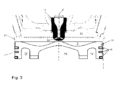
Fig. 3 is a side view in cross section of the delivery device;
Fig. 4 is a side view of the fluid channel and cam assembly in one embodiment;
Fig. 5 is a perspective view of the pump mechanism of Fig. 3;
Fig. 6 is an end view in cross section of the pump mechanism of the delivery
device
of Fig. 5;
Fig. 7 is a side view in cross section of the pump mechanism showing the cams
in a
first position;
Fig. 8 is a side view in cross section of the pump mechanism showing the cams
in a
second position;
Fig. 9 is a side view in cross section of the pump mechanism showing the cams
in a
third position;
Fig. 10 is a perspective view of the pump mechanism in another embodiment; and
Fig. 11 is cross sectional view of a further embodiment of the pump mechanism.
7
CA 03194298 2023- 3- 29
WO 2022/076337
PCT/US2021/053458
Detailed Description of Embodiments
[0024] Reference will now be made in detail to embodiments of the present
invention, which are
illustrated in the accompanying drawings, wherein like reference numerals
refer to like elements
throughout. The embodiments described herein exemplify, but do not limit, the
present invention
by referring to the drawings.
[0025] It will be understood by one skilled in the art that this disclosure is
not limited in its
application to the details of construction and the arrangement of components
set forth in the
following description or illustrated in the drawings. The embodiments herein
are capable of
being practiced or carried out in various ways. Also, it will be understood
that the phraseology
and terminology used herein is for the purpose of description and should not
be regarded as
limiting. The use of "including," "comprising," or "having" and variations
thereof herein is meant
to encompass the items listed thereafter and equivalents thereof as well as
additional items.
Unless limited otherwise, the terms "connected," "coupled," and "mounted," and
variations
thereof herein are used broadly and encompass direct and indirect connections,
couplings, and
mountings. In addition, the terms "connected" and "coupled" and variations
thereof are not
restricted to physical or mechanical connections or couplings. Further, terms
such as up, down,
bottom, and top are relative, and are employed to aid illustration, but are
not limiting. Any of the
embodiments and/or elements and features disclosed herein may be combined with
one another
to form various additional embodiments not specifically disclosed, as long as
they do not
contradict or are not inconsistent with each other. Terms of degree, such as
"substantially",
"about" and "approximately" are understood by those skilled in the art to
refer to reasonable
ranges around and including the given value and ranges outside the given
value, for example,
general tolerances associated with manufacturing, assembly, and use of the
embodiments. The
term "substantially" when referring to a structure or characteristic includes
the characteristic that
is mostly or entirely.
[0026] The illustrative embodiments are described with reference to diabetes
management using
insulin therapy. It is to be understood that these illustrative embodiments
can be used with
8
CA 03194298 2023- 3- 29
WO 2022/076337
PCT/US2021/053458
different drug therapies and regimens to treat physiological conditions other
than diabetes using
different medicaments other than insulin.
[0027] Fig. I is a perspective view of an exemplary embodiment of a medicament
delivery
device. In one embodiment, the delivery device is shown as a patch pump 1. In
other
embodiments, the delivery device can have other structures and delivery
mechanisms, such as an
infusion set and pump arrangement. The delivery device as described herein is
configured for
delivering insulin in the form of an insulin solution to a patient at a
controlled rate. Fig. 2 is an
exploded view of the various components of the patch pump of Fig. 1,
illustrated with a housing
20 forming a main cover. The various components of the patch pump I include: a
reservoir 4 for
storing insulin, a pump 3 for pumping insulin out of the reservoir 4, a power
source 5 in the form
of one or more batteries, an insertion mechanism 7 for inserting an inserter
needle with a cannula
into a user's skin, and control electronics 8 in the form of a circuit board
with optional
communications capabilities to outside devices such as a remote controller and
computer,
including a smart phone; a pair of dose buttons on the housing 20 for
actuating an insulin dose,
including a bolus dose. A base 22 for supporting the components may be
attached to the housing
20 by suitable fasteners or snap connectors. The patch pump I also includes
various fluid
connector lines that transfer insulin pumped out of the reservoir 4 to the
infusion site. The
cannula can be a rigid cannula or flexible catheter as known in the art.
[0028] The wearable medical delivery device (e.g., insulin delivery device
(IDD) such as patch
pump 1 can be operable in conjunction with a remote controller that
communicates wirelessly
with the pump 1 that can include a graphical user interface (GUI) display for
providing a user
visual information about the operation of the patch pump 1 such as, for
example, configuration
settings, an indication when a wireless connection to the patch pump is
successful, and a visual
indication when a dose is being delivered, among other display operations. The
display can
include a touchscreen display that is programmed to allow a user to provide
touch inputs such as
a swipe to unlock, swipe to confirm a request to deliver a bolus, arid
selection of confirmation or
settings buttons, among other user interface operations.
[0029] The delivery device shown as a patch pump 1 has a main cover that forms
the housing 20
with an internal cavity. The base 22 carries and supports various components
as described below.
A hermetic seal between the cover and the base prevents fluid ingress and
prevents other
9
CA 03194298 2023- 3- 29
WO 2022/076337
PCT/US2021/053458
particles from passing the seal. Embodiments of the delivery device also
includes a vent or a vent
membrane to provide pressure equalization between the interior of the housing
and the exterior
atmosphere.
[00301 Referring to Fig. 3, the housing 20 and the base 22 define an interior
cavity divided by a
wall forming a barrier 24 into a first internal space 26 forming a first
cavity and a second internal
space 28 forming a second cavity. The barrier 24 can be part of the housing or
cover and
integrally formed as a unitary structure with the cover. Alternatively, the
internal barrier can be
formed with the base or can be formed as a separate unit coupled to the base
and the cover. In
the embodiment shown, the barrier 24 is preferably sealed to a protruding rib
30 on the base 22
such that the interface between the barrier 24 and the rib 30 is hermetically
joined using an
appropriate sealing method. The barrier 24 separates the first internal space
26 from the second
internal space 28 and protects the first internal space from fluid ingress
from the second internal
space. According to one embodiment, the second internal space is not sealed
from fluid ingress.
[00311 The first internal space 26 includes components such as the pump
mechanism 36, the
force sensing resistor, and the electronics for controlling the operation of
the delivery device and
controlling and monitoring the delivery of the medication to the patient.
Examples of the
electronics include semiconductor chips, controllers, diodes, antennas, coils,
batteries, other
components (resistors and capacitors, for example) and circuit boards used to
operate arid control
the patch pump I and operate the pump. As readily understood by the skilled
artisan, it is
desirable to have a dry environment for proper operation of these components,
particularly the
electronics. The second internal space 28 includes the insertion mechanism 7
and the delivery
assembly such, as a cannula 32. According to one embodiment, the insertion
mechanism 7
interfaces with the skin of a patient and the second internal space 28 can be
neither a
hermetically sealed environment, nor a liquid-tight environment. Various
insertion mechanisms
can be used as known in the art.
[0032] According to one embodiment, the components of the first internal space
26 are different
from the components of the second internal space 28. Alternatively, the first
internal space and
the second internal space can share some of the same components. For example,
in some
embodiments, portions of the reservoir 4 are disposed in both the first and
second internal
spaces. When the reservoir and the insertion mechanism 7 are separated by the
barrier 24, the
CA 03194298 2023- 3- 29
WO 2022/076337
PCT/US2021/053458
two internal spaces fluidly communicate for effective operation of the
delivery device and the
transfer of fluid from the reservoir and the pump mechanism.
[00331 The delivery device can include a fill port connected to a conduit for
supplying the
medicament to the reservoir 4. The fill port can be disposed in the first
internal space 26 or the
second internal space 28, but is typically located in the first internal space
26. In some
embodiments, the fill port includes a portion that serves as part of the flow
path for medicament
exiting the reservoir 4.
[00341 During use, the bottom surface of the delivery device is oriented
toward the skin of the
patient. In some embodiments, the bottom surface includes an adhesive that
removably attaches
the base to the skin of the patient. Alternatively, an adhesive pad 34, as
illustrated in Fig. 1,
adheres to both the bottom surface and the skin of the patient. Typically,
3MTm medical tape
(e.g. product no. 1776) is the adhesive used, although various types of known
industry adhesives
can be used. The adhesive is selected to ensure compatibility with human skin
to prevent
undesired reactions. Also, compatibility of the adhesive and the insulin is
considered in case that
the adhesive and the insulin accidentally mix.
[00351 The pump mechanism 36 in one embodiment is peristaltic pump for
delivering the
medication, such as insulin, from the reservoir to the delivery assembly, such
as the cannula 32
or flexible catheter. The pump mechanism 36 is formed with at least one
component part of the
delivery device. In the embodiment disclosed, the pump mechanism 36 is formed
with the base
22. As shown in Fig. 4, the base 22 has a top surface 38 facing the internal
cavity 28 and a
bottom surface 40 facing outwardly for contacting the patient during use. The
delivery
mechanism, such as a cannula, projects from the bottom surface 40 where the
cannula is inserted
into the patient to a selected depth for delivering the medication to the
intended depth and
location in the patient.
[0036] As shown in Fig. 4, the top surface 38 of the base 22 includes at least
one recess 42 for
forming a fluid channel 44 through the base 22 from a first location to a
second location. The
recess 42 forming the fluid channel 44 can have a substantially U-shape or
groove shape with a
longitudinal dimension extending parallel to the plane of the base 22. In the
embodiment shown,
the recess 42 has an open side facing outward from the top surface 38. The
fluid channel 44
11
CA 03194298 2023- 3- 29
WO 2022/076337
PCT/US2021/053458
extends in a longitudinal direction parallel to the plane of the base 22 and
is configured and
located to direct a fluid from a first location in the device to a second
location in the device. In
the embodiment shown, the fluid channel 44 is formed by the recess 42 having
an inlet end 46
and an outlet end 48. The recess 42 forming the fluid channel 44 in the
embodiment shown is
molded in the top surface 38 of the base 22. The fluid channel 44 is
configured where the inlet
end 46 communicates with the reservoir to receive the medication and the
outlet end 48
communicates with the delivery mechanism, such as the cannula 32.
[0037] The fluid channel 44 is enclosed by a flexible membrane 50 to enclose
the recess 42 and
form a fluid tight channel between the base 22 and the membrane 50 for the
fluid passing
between the components and between the inlet end 46 and the outlet end 48. The
flexible
membrane 50 can be a flexible sheet or film bonded to the top surface 38 to
overly and cover the
recess as shown in Fig. 4 to form a fluid tight path for the medicament. The
membrane 50 has a
shape to conform the top surface 38 of the support and the recess that forms
the channel. In the
embodiment shown, the top surface 38 of the support is substantially flat and
the membrane 50 is
substantially flat. The membrane 50 has a bottom surface attached to the top
surface of the base
22 and a top surface facing away from the base 22.
[0038] In the embodiments shown, the recess is formed in the base 22 on the
top surface facing
the cavity of the delivery device. In other embodiments, a separate plate can
be provided with
the recess formed in a top surface of the plate. The plate can then be coupled
to the base by a
suitable attachment mechanism.
[0039] A coupling 52 is formed on the top surface 38 at the outlet end 48 of
the fluid channel 44
with an open end for receiving a flexible conduit 54. In the embodiment shown,
the conduit
extends between the outlet end of the channel to the cannula 32 of the
insertion mechanism for
supplying the cannula with the medicament and delivering to the patient. The
cannula of the
delivery device has a lumen for introducing the medicament into the patient.
The cannula can be
hollow steel cannula or a flexible catheter as known in the art.
[0040] A coupling 56 on the top surface 38 at the inlet end 46 of the fluid
channel 44
communicates with the fluid channel. In the embodiment shown, the coupling 56
receives a
conduit 58 that extends between the reservoir and the channel for supplying
the medicament
12
CA 03194298 2023- 3- 29
WO 2022/076337
PCT/US2021/053458
from the reservoir to the inlet of the fluid channel. In the embodiment shown,
the fluid channel
extends parallel to a plane of the base 22 for directing the fluid between two
spaced-apart
locations on the top face of the base. The fluid channel is located and has a
length to provide
fluid communication between the operating components of the delivery device
located in the
cavity of the housing. In one embodiment, the channel is oriented or
positioned so that the inlet
end and the outlet end are on opposite sides of the barrier wall 24 to provide
fluid
communication between the first internal space 26 and the second internal
space 28.
[0041] Referring to Fig. 4, the pump mechanism 36 includes a drive assembly
including a cam
assembly 60 and a cam follower assembly 62. The membrane 50 is attached to the
top surface of
the base 22 and is made of a flexible material, such as a flexible polymer,
that can be deflected
inwardly by the cam assembly. The cam assembly 60 in the embodiment shown
includes a
plurality of rotating cams 64, 66 and 68 mounted on a rotating drive shaft 69
that is supported by
a suitable support to orient the cams and drive shaft in a position to operate
the pump
mechanism. The drive shaft 69 is connected to a drive motor 71 as shown. Each
cam member
64, 66, 68 includes a lobe 70 oriented for actuating a cam follower of the cam
follower assembly
at a selected timing sequence to pump the fluid from the inlet end 46 to the
outlet end 48. As
shown in Figs. 4 and 5, three cams 64, 66 and 68 are provided on the shaft 69.
The lobes 70 of
each cam is oriented about 120 apart. In other embodiments, more than three
cams can be
provided where the lobes sequentially engage the membrane to pump the fluid
through the fluid
channel
[0042] The cam follower assembly 62 is mounted on a support 72 coupled to the
top surface 38
of the base 22 to support the cam follower assembly next to or adjacent the
membrane 50 and the
cam assembly 60. In the embodiment shown, the cam follower assembly 62 is a
one-piece
member having separate members for engaging a respective cam 64, 66, and 68
and for engaging
the membrane 50. The cam follower assembly 62 can be made of a stamped metal
having
sufficient flexibility to deflect when actuated by the respective cam 64, 66,
and 68. The
flexibility of the cam follower assembly enables efficient contact with the
membrane 50 to
deflect the membrane to close the fluid channel. In other embodiments, the
membrane can be
made of shape memory alloy that can be actuated the cam assembly.
13
CA 03194298 2023- 3- 29
WO 2022/076337
PCT/US2021/053458
[0043] The cam follower assembly 62 as shown has a body portion 74 coupled to
the support 72
and a plurality of flexible portions shown as flexible legs 76 extending from
the body portion 74.
In the embodiment shown, the legs 76 extend in a plane parallel with the plane
of the body
portion 74. In other embodiments, the legs 76 can be independent of the body
portion and
formed by separate members independently supported by a suitable support. In
the embodiment
shown, the legs 76 are cantilevered from the body portion 74 and are
sufficiently flexible to
deflect when contacted by the lobes 70 on the respective cam 64 to deflect the
membrane 50.
The legs 76 have a distal end 78 with a top surface 80 for contacting the
respective cam and a
bottom surface 82 for contacting the membrane 50 at a specific location along
the length of the
fluid channel 44. The bottom surface 82 in the embodiment shown has an
integrally formed
protrusion 84 with a shape and dimension complementing the shape and dimension
of the recess
42 that forms the fluid channel 44. In the embodiment shown, the protrusion 84
has a convex
shape forming a dome-like shape corresponding substantially to the cross
sectional configuration
of the recess.
[0044] As shown in Fig. 4, the recess 42 has a plurality of spaced-apart
recessed wells 86 formed
in a bottom surface of the recess. Each well 86 is spaced apart a distance
corresponding to the
spacing of the cams 64, 66, and 68, and spaced corresponding to the location
of the protrusions
84 of the cam follower assembly 62. The shape and dimension of the wells 86
complement the
shape and dimension of the protrusions 84. During the operation of the
delivery device, the shaft
69 is rotated by the motor 71 to rotate the cams so that lobes 70 sequentially
contact the
membrane 50. The lobes 70 have a. dimension to actuate the legs 76 of the cam
follower
assembly 60 so that the membrane is deflected inwardly to close the fluid
channel in sequence
and provide a peristaltic pumping action.
[0045] The membrane 50 is formed from a flexible material that can be
depressed and deformed
to the configuration of the fluid channel to close the fluid channel wen the
cam actuates the
respective can follower. The membrane can be, for example a plastic material,
that has sufficient
memory to return to its original configuration when the force by the cam
follower is released to
open the fluid channel. The cam follower is made of a material that has
sufficient memory to
return to its original shape and configuration to allow the membrane to return
to its original
configuration to open the channel.
14
CA 03194298 2023- 3- 29
WO 2022/076337
PCT/US2021/053458
[0046] Fig. 7 shows the first cam 64 actuating the respective leg 76 of the
cam follower
assembly 62 to deflect the membrane 50 into the recess 42 to close the fluid
channel. The cam 64
is configured to close the fluid channel for at least about 240' of rotation
of the shaft. As shown
in Fig. 8, the cam assembly is configured so that the second cam 66 rotates
into contact with the
respective leg of the cam follower assembly to actuate the cam follower to
close the fluid
channel at the point of the second cam 66 while the fluid channel is closed at
the point of the first
cam 64. The actuation of the second cam 66 to close the fluid channel forces
the fluid in fluid
channel toward the outlet end of the fluid channel in the direction indicated
by the arrow in Fig.
8. As shown in Fig. 9, the third cam 68 then rotates into contact with the
respective cam follower
to deflect the membrane 50 to close the fluid channel at the point of the
third cam 68 while the
first cam 64 is rotated to a position to open the fluid channel and the second
cam 66 remains in
contact with the cam follower to retain the fluid passage closed at the
location of the second cam.
The actuation of the third cam while the fluid channel is closed at the
location of the second cam
forces the fluid toward the outlet end of the fluid channel in the direction
of the arrow shown in
Fig. 9. In this manner the rotation of the shaft 69 and the cams 64, 66, and
68 sequentially close
and open of the fluid channel to pump the fluid through the fluid channel. The
cams 64, 66, and
68 are configured and oriented on the shaft so that the fluid channel is
always closed by one of
the cams and cam followers to control the fluid flow in the direction toward
the outlet end of the
fluid channel.
[0047] Fig. 10 shows another embodiment of the pump mechanism. In this
embodiment,
separate cams and cam followers 90 are mounted in a suitable support for
linear movement in a
direction perpendicular to the plane of the membrane 50. Each of the cam
followers 90 have a
first end that contact the respective cam 64, 66, 68 and a second end
contacting the flexible
membrane 50. The rotation of the cams produce the sequential movement to
depress the
membrane and produce the peristaltic pumping action. As shown in Fig. 10,
spring members 90
are provided to bias the cam followers 90 away from the membrane 50.
[0048] Fig. 11 shows another embodiment of the pump mechanism where each of
the cams are
separate units that cooperate with separate cam followers. In the embodiment
shown, each cam
member 94 is operatively connected to a separate drive mechanism 96. The drive
mechanisms
96 are connected to a control unit 98 to actuate the drive mechanisms 96 and
the respective cam
CA 03194298 2023- 3- 29
WO 2022/076337
PCT/US2021/053458
member 94 in the suitable sequence to produce the peristaltic pumping action.
In this
embodiment, each cam member is associated with a separate flexible membrane
100. The cam
followers 100 cam be configured as in the previous embodiments. Each of the
cam followers are
configured to move in a linear direction perpendicular to the plane of the
membrane and the
longitudinal dimension of the fluid channel with no lateral or transverse
movement relative to the
membrane.
[0049] The pump assembly as shown, minimizes the number of different materials
that contact
the medication during the pumping action to increase stability, reduce shear
stress and avoid
contact of the medication with lubricants and metal or plastic parts of pump
mechanism.
[0050] In the embodiment shown, the fluid channel is formed in a top surface
of the base of the
delivery device. In other embodiments, the fluid channel can be formed in a
separate plate that
can be mounted within the cavity of the delivery device or attached to the
base or wall of the
housing. The fluid channel and the pump mechanism can be formed as separate
unit that is
attached base or other part of the delivery device. The fluid channel can be
formed in a support
member that also supports the cam assembly and cam follower assembly, which
can mounted
within the housing of the delivery device. The delivery device can be
constructed so that various
components can be replace or discarded after use while some parts are
reusable. In one example,
the base supports the fluid channel which can be separated from the pump
mechanism so that the
pump mechanism can be retained and reused. The base is replaced after use to
avoid
contamination of the fluid channel between uses.
[0051] The delivery device is particularly suitable for delivering insulin to
the patient over an
extended period of time. The delivery device is actuated to insert the carmula
36 into the patient.
The pump is actuated to carry the insulin at a controlled rate from the
reservoir 4 to the cannula
36 where the insulin is introduced into the patient.
[0052] In the embodiment illustrated, the pump mechanism includes the micro-
cam assembly
and the micro-cam follower assembly for advancing the fluid medication through
the fluid
channel. In other embodiments, the pump assembly does not include the cam
follower assembly
so that the cam members contact the membrane directly to deflect the membrane
into the fluid
channel to produce the peristaltic pumping action.
16
CA 03194298 2023- 3- 29
WO 2022/076337
PCT/US2021/053458
[00531 As shown in the drawings, the fluid channel can extend below the
barrier wall 24
between the first interior area 26 and the second interior area 28. In this
manner, the fluid
channel is able to carry the fluid or medication between the different
enclosed areas without
passing directly through the barrier 24.
100541 The fluid channels are recessed from (or inscribed into) the surface of
the base by a
molding process, such as injection molding, or by a cutting process, such as
milling. In other
embodiments, the fluid channels are disposed on the main cover of the housing,
or on the base
within the inner cavity of the housing. Similar fluid channels can be
positioned in a plurality of
locations in the device. The cross-sectional shape and dimension of the fluid
channels is defined
by the desired flow characteristics. Exemplary cross-sectional profiles of the
fluid channels
include square, rectangular, and semi-circular One skilled in the art will
appreciate that other
cross-sectional profiles can be used without departing from the scope of the
present invention.
100551 Although only a few embodiments of the present device are shown and
described, the
present device is not limited to the described embodiments. Instead, it will
be appreciated by
those skilled in the art that changes may be made to these embodiments without
departing from
the principles and spirit of the device. Different embodiments can be combined
with other
embodiments as long as they are not inconsistent with each other. It is
particularly noted that
those sk:illed in the art can readily combine the various technical aspects of
the various elements
of the various exemplary embodiments that have been described above in
numerous other ways,
all of which are considered to be within the scope of the disclosure and
equivalents thereof
17
CA 03194298 2023- 3- 29