Note: Descriptions are shown in the official language in which they were submitted.
CA 03194506 2023-03-08
1
Method and Apparatus for Automated Quality Control for Cutting Machines of
Flexible
Material Parts
Technical Field of the Invention
[oil The invention relates to a method and an apparatus for automated quality
control for cutting
machines of flexible materials, especially of fabric material parts, e.g.,
cutout of a material web of
flexible material. The invention is especially suited for the quality control
of fabric material parts or
patterns for airbags, e.g., from One-Piece-Woven fabric (OPW fabric) or other
fabric, but not limited
to such applications. Preferably, the invention is applied to a laser cutting
machine.
[02] In the previously known methods for manufacturing material parts cut from
a flexible material,
as for example airbags or airbag parts, the flexible material, especially in
the form of fabric, technical
textiles, carbon fiber, fiberglass, airbag or OPW fabric, respectively, seat
covers, or coated or
uncoated, single-layered or multi-layered metal or plastic sheets, is supplied
on an essentially
horizontal conveyor to a cutting machine, especially a laser cutting machine.
In certain cases, and
depending on the application, already before the cutting process, the flexible
material may be readily
welded, adhered, weaved, or preprocessed in general.
[03] In conventional cutting machines, after the cutting process, the cut
material parts are manually
doffed and subsequently laid out again in a separate inspection station and
undergo a visual and/or
haptical quality control by employees.
[04] The quality requirements for cut parts, especially for airbags, are very
high, as these components
are subjected to extreme strains in an accident, and the airbags can only
increase the safety of the
passengers when functioning flawlessly. This applies in general to all
flexible materials, from which
material parts are cut. The modern cutting technology, especially by means of
a laser, allows for
complex cutting sequences, the optical inspection of which is costly and prone
to error, especially
when this inspection is performed manually by humans.
[05] In addition to an increase of the number of the airbags in a vehicle,
also the size of the airbags
themselves increases, in some instances, the airbags extend through the whole
transverse side of a
vehicle from the A-pillar to the C-pillar. Therefore, such complex airbag
parts have dimensions of,
in some instances, multiple meters. Despite a steady increase of the
manufacturing quality, a quality
control in this kind of components remains inevitable.
[06] The previous manual quality control is a monotone, demanding activity,
yet at the same time
requires a high degree of focus. With the increasing number of airbags in a
vehicle and an ever-
growing complexity of the individual airbag parts, laying them out and the
subsequent manual
Date Recue/Date Received 2023-03-08
CA 03194506 2023-03-08
2
quality control become increasingly costly and complex. In addition, at
smaller quantities and a
larger number of different parts, securely recognizing deviations of the
individual parts from the
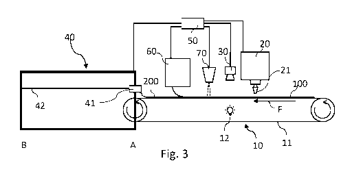
standard becomes especially difficult for the employees. Faster cutting
processes and the associated
growing throughput additionally increase the burden of the employees and the
quality control may
become the limiting factor in the capacity of the facility. In addition, the
manual quality control is
subject to the subjective perception of the employe. This may lead to a
different sorting depending
on the employee in the quality control and thus to different quality
standards. In the case of an
absence of employees, they are often difficult to replace, and manufacturing
may stall. Thus, it may
occur that, due to errors of the employee, defective parts reach the further
production process as
to good parts.
[07] A repositioning of finished cut parts to separate quality control tables
or stations has the
disadvantage that the position of the cut material part is changed, and
potentially existing tabs or
protrusions are stored falsely or folded over and thus, all deviations cannot
be recognized any longer.
[08] Furthermore, in many applications, a traceability of the production is
required. Many customers
of such cut material parts demand, for example, for the quality control and/or
the further machining
information on the cut material parts, including quality data, cutting data or
coordinates, machining
data, machining parameters. This information is established during the cutting
process and/or exists
at the time of the cutting process and/or is delivered already by preliminary
stages of the production
or the manufacturing, respectively, od the material to a cutting machine.
[09] Therefore, an object of the invention is to specify an automated method
and an apparatus
enabling a quick, reliable, and reproducible quality assurance removing the
above disadvantages of
the previous quality assurance and being easily integrated in existing
machines, in order to be able
to meet novel quality standards with an existing machine.
110] A further object of the invention is to specify an automated method and
an apparatus by which
information for quality assurance may be securely and efficiently associated
to the cutout material
parts.
111] These objects are solved by the subject matters of the independent
claims. Advantageous
developments of the invention are given in the dependent claims.
[12] The invention is based on the idea of not having to additionally move, at
a cutting machine, the
cutout material parts and creating a quality result by means of an inline
quality control. By the lack
of relocation of the cutout material parts, defects potentially caused or
concealed, respectively, by
repositioning may be avoided. Further, the inline quality control leads to an
increase of the
throughput and to a high reproducibility.
Date Recue/Date Received 2023-03-08
CA 03194506 2023-03-08
3
[13] Another aspect of the invention relates to marking the cutout material
parts. Thus, information
on the quality result may be securely attached or allocated to the cutout
material parts, to thus ensure
a quality assurance and/or securely recognize defective parts, and also one or
more additional
information on the material and/or the previous machining process may be
attached or allocated.
[14] In a first aspect, a cutting machine is specified, comprising: a conveyor
for conveying flexible
material; a machining unit for cutting the flexible material into one or more
material parts; a
recognition unit for detecting the flexible material and/or at least one cut
material part, the
recognition unit arranged in the conveying direction after the machining unit,
and a control unit,
configured to generate, based on information of the recognition unit and/or
marking information, a
to quality result and, if applicable, control the cutting machine.
[15] Thus, a recognition unit is arranged here as an inline quality control
unit immediately after the
machining unit for cutting. The cutout material parts are moved out of the
machining unit by the
conveyor and may thus immediately undergo quality control without further
repositioning. That is,
the flexible material parts may not be changed in their position and the
quality control unit, also
referred to as recognition unit, may recognize all cuttings, seams, weavings,
holes, tabs, or
protrusions at the intend position and inspect whether they match the cutting
data and/or reference
data or lie within the given tolerances, respectively.
[16] Alternatively or additionally, the recognition unit may also be placed
before the machining unit,
for example to recognize material defects also already before the cutting.
[17] In the generation of the quality result, also marking information
stemming from preliminary
production stages or material manufacturing may be co-processed additionally.
[18] Alternatively or additionally, the cutting machine may comprise a marking
unit for marking the
flexible material and/or the at least one cut material part based on the
quality result. The marking
may, for example, occur by imprinting on the cut material part or by cutting
or marking (scribing,
partial melting the surface) the cut material part. Preferably, the cutting or
marking, respectively,
may still be made by the machining unit, e.g., by a laser. There may also
existing a downstream
printer for imprinting.
[19] The marking unit may be arranged in the conveying direction before and/or
after the machining
unit. A marking unit before the machining unit may, for example, apply
information on the material
or material defects to the material at the corresponding position. Thus, it is
easier for the recognition
unit, in the quality control, to recognize a material defect already existing
before the cutting.
Date Recue/Date Received 2023-03-08
CA 03194506 2023-03-08
4
[20] Alternatively or additionally, the marking unit may also be arranged in
the conveying direction
after the recognition unit to thereby also let the quality result feed into
the marking. The marking,
especially of recognized defects, is very important to prevent a later further
processing of defective
parts as safely as possible.
[21] In another aspect, a cutting machine is specified, comprising: a conveyor
for conveying flexible
material; a machining unit for cutting the flexible material into one or more
material parts; a marking
unit for marking the flexible material and/or the at least one cut material
part based on information
of the cutting machine and/or of the flexible material, the marking unit
arranged in the conveying
direction before and/or after the machining unit.
to [22] In this aspect, no recognition unit must be provided, and the
marking unit serves mostly for the
application of information of the material and/or the machining process.
[23] Such a cutting machine may of course also be extended by the above
recognition unit. The
recognition unit serves for detecting the flexible material and/or at least
one cut material part, the
recognition unit arranged in the conveying direction after and/or before the
machining unit.
[24] The control unit may be configured to, based on information of the
recognition unit and/or
marking information, to generate a quality result and, if applicable, control
the cutting machine.
[25] Preferably, the flexible material may be a flexible fabric, a single-
layered or multi-layered
plastic sheet or a single-layered or multi-layered metal sheet, a textile,
technical textile, e.g., a
carbon fiber or fiberglass material (e.g., aramid), and/or an at least partly
single-layered, double-
layered, and/or multi-layered fabric. The flexible material may be uncoated or
coated on one or both
sides.
[26] Preferably, the flexible material may be a flexible fabric for airbag
production.
[27] Preferably, the flexible material may be conveyed from a reel onto the
conveyor. A delivery of
the flexible material in large already cut plates or panels is also possible.
[28] In a preferred development, the cutting machine may comprise a doffing
apparatus. The doffing
apparatus serves for doffing the at least one cut material part off the
conveyor. The doffing apparatus
may be arranged after the recognition unit or, in case the marking unit
exists, after the marking unit.
[29] In a preferred development, the cutting machine may comprise a residual
material doffing
apparatus or also residual fabric extraction apparatus for doffing a residual
material or residual
fabric. The residual fabric extraction apparatus may be arranged in the
conveying direction before
or after the recognition unit and/or in the conveying direction before or
after the marking unit.
[30] In an optional arrangement of the residual material doffing apparatus
before the recognition
unit, the quality control to be performed is easier, as the edges of the
cutout material part may be
Date Recue/Date Received 2023-03-08
CA 03194506 2023-03-08
recognized more easily. However, it must be accepted thereby that, by doffing
the residual
material/residual fabric, if applicable, a change in position of the cutout
material part may occur and
possibly badly or incompletely cut areas may lead to a stop of the process.
[31] In an arrangement of the residual material doffing apparatus after the
recognition unit, the
5 quality control to be performed is more demanding, as now, the cuts need
to be recognized.
However, it is accomplished thereby that the cutout material part for the
quality control remains at
its position.
[32] The residual material doffing apparatus may be arranged in the conveying
direction at the same
position as the doffing apparatus or in the conveying direction after the
doffing apparatus. This is
to advantageous when the required length in the hall for the conveyor is
limited.
[33] In a preferred development, the control unit may be configured to
control, based on information
of the recognition unit and/or marking information, the doffing apparatus
and/or the residual
material doffing apparatus and/or the marking unit. Thus, it is possible,
based on the quality result,
to control and, if applicable, stop the subsequent units or, with well
recognized material parts, the
corresponding doffing by the doffing apparatus, respectively.
[34] In a preferred development, the recognition unit may comprise a camera
and/or a transmitter
and receiver and/or one or more sensors, and/or an illumination unit.
Depending on the material,
different equipment may be deployed for quality control. So, for example with
single-layered or
multi-layered fabric, it is reasonable to process the cutout material part
with a camera and depending
on the thickness of the fabric with additional illumination. In multi-layered
coated foils, an
ultrasound apparatus consisting of transmitter and receiver may be deployed.
[35] Preferably, the illumination unit may output light with a wavelength
adapted to the material or
a material composition.
[36] Preferably, the flexible material may lie between transmitter and
receiver and the transmitter
may, e.g., output ultrasound, which is then received by the receiver to obtain
information on the
material composition of the flexible material.
[37] The recording area of the camera or of the sensor may comprise a square,
rectangular, and/or
linear shape. So, for example, strip-shaped images may be recorded, which are
then composed in
the control unit to recognize, for example by means of contrast differences,
the cuttings, seams,
holes etc. Depending on the application and e.g., the conveying speed, also a
strip-shaped partial
image may already be inspected for defects or tolerances, respectively.
[38] Preferably, the illumination unit may be arranged on a side of the
recognition unit opposite the
flexible material and/or facing the flexible material.
Date Recue/Date Received 2023-03-08
CA 03194506 2023-03-08
6
[39] The illumination unit may also be arranged between the conveyor and the
flexible material.
[40] In a preferred development, the quality result may be based on an
inspection of the position of
the cuttings and the number of the seams and/or the position and number of
cutouts/holes and/or on
the quality of weaved places and/or welding seams and/or adhesive areas and/or
on the position of
the weaved places, adhesive areas, and/or welding seams and/or on the position
of markings at the
flexible material.
[41] In a preferred development, the control unit may be configured, to
examine the at least one
cutout material part for warpage. To do so, it may be inspected, whether the
length and/or the width
of the at least one cutout material part corresponds to the target or
reference specifications and/or
to whether tabs, protrusions, or cutouts are arranged at the at least one
cutout material part in the
respective correct position.
[42] In a preferred development, the control unit may be configured to
display, through an optical
output unit at the machine, e.g., in the form of a lamp, or at a display, an
approved airbag part. That
is, with a positive quality result, in the lane of the approved airbag part, a
green lamp or LED lights
up, or the machine operator obtains this information at a display, wherein the
good airbag parts on
the display are colored with a color predetermined for approval.
[43] Alternatively or additionally, it is also possible, e.g., through an
approved airbag part to display,
through a projection of the quality result on the airbag part. That is, a
green dot, e.g., may be
irradiated onto an approved airbag part.
[44] With a negative quality result for a defective airbag part, the optical
output unit may display this
airbag part as a scrap part or as a reworkable airbag part, e.g., by red for a
scrap part and yellow for
a reworkable airbag part.
[45] Also here, the output of the quality result may occur by means of a
projection onto the airbag
part or also onto the material part in general.
[46] In general, the control unit may output its quality result through an
optical output unit and/or at
a display or display the quality result for a material part by projection onto
the material part.
[47] In a preferred development, the recognition unit may recognize a marking
of material defects
on the flexible material.
[48] Material defects of the flexible material or their position, already
known before the cutting, may
also be included in a file being processed by the control unit of the cutting
machine to
correspondingly control the doffing apparatus and, if applicable, the marking
unit and not to doff
and/or mark defective the defective material part.
Date Recue/Date Received 2023-03-08
CA 03194506 2023-03-08
7
[49] In a preferred development, the flexible material may be a fabric band,
especially for airbag
production, which has multi-layered areas and single-layered areas, e.g., a
one-piece-woven (OPW)
fabric.
[50] Preferably, the machining unit may be a laser cutting apparatus for
cutting out fabric material
parts for airbag production.
[51] In a preferred development, the control unit may be configured to, at a
positive quality result,
approve the corresponding cut fabric material part for doffing and, at a
negative quality result,
categorize a defective airbag part as a scrap part or as a reworkable airbag
part.
[52] In a preferred development, the control unit may be configured to control
the doffing apparatus
such that the scrap parts and the reworkable OPW fabric material parts are
stored separately from
each other.
[53] Preferably, the control unit may be configured, based on the information
of the recognition unit,
to identify a defect and/or a cause of defect and/or to correct these and/or
output hints for defects
and/or wear to the cutting machine. Thus, repeated defects may be avoided, and
the scrap rate
reduced. By outputting the defect as an optical or acoustical warning signal,
the machine operator
may intervene and, if applicable, make changes for following cutting
processes, in order improve
the quality for subsequent parts.
[54] In a preferred development, the control unit may be configured to carry
out the quality control
during a continuous and/or discontinuous and/or stopped operation of the
cutting machine. That is,
the recognition unit may also record a photo with a stopped conveyor belt and
then compose this
with the following photos at continuation of the process, to recognize the
posture of the cuttings,
seams, holes etc.
[55] In another aspect, a method for automated inline quality control of at
least one material part,
cutout from a flexible material is specified, comprising the following steps:
supplying a flexible
material on a conveyor, cutting the flexible material by means of a machining
unit into one or more
material parts; detecting at least a part of the flexible material and/or of
the cutout material part by
means of a recognition unit; and performing a quality control based on
information of the
recognition unit and at least one reference value.
[56] Preferably, the method comprises the control of the machining unit and/or
of a doffing apparatus
and/or of a residual material doffing apparatus and/or of a marker based on
the result of the quality
control.
[57] Since the flexible material of the invention is conveyed on the conveyor,
e.g., a printer or a laser
marker of the marking unit may mark the material part, even without quality
control.
Date Recue/Date Received 2023-03-08
CA 03194506 2023-03-08
8
[58] A reworkable material part may include, e.g., a small hole, which was cut
out by means of a
laser and then, by the hot edges of the material, adhered to the hole cutout
again.
Short Description of the Drawings
Fig. 1 shows a perspective depiction of a conventional cutting machine
with manual fabric
material partial doffing and quality control.
Fig. 2 shows a schematic depiction of a first embodiment of the cutting
machine of the
invention with inline quality control.
Fig. 3 shows a schematic depiction of a second embodiment of the cutting
machine of the
invention with inline quality control.
to -- Fig. 4a, b show, in a schematic depiction, variants of a third
embodiment of the inline quality
control of the invention.
Fig. 5 shows a schematic depiction a retrofit solution of the inline
quality control of the
invention at existing OPW cutting machines.
Fig. 6 shows a cutout material part.
Fig. 7 shows another cutout material part with tolerance ranges;
Fig. 8 shows a method of the inline quality control of the invention.
Embodiments of the Disclosure
[59] In the following, the invention is described by means of an airbag
cutting machine. However,
the invention is not limited to cutting and inspecting or marking,
respectively, OPW fabric and can
-- be transferred to many areas of application, in which flexible materials
are cut by a cutting process.
So, it is possible to cut single-layered or multi-layered sheets or foils from
metal or plastic, coated
or uncoated, by means of a laser cutting machine. These cut material parts may
be, e.g., battery
electrodes, sheet or foil parts, or seat covers.
[60] In the following are, identical reference signs are used for identical
and similarly acting
__ elements, if not indicated otherwise. The depicted elements are not to be
considered to be drawn to
scale, rather, individual elements may be depicted excessively large for
better understanding.
[61] Fig. 1 shows a conventional cutting machine. After the cutting process of
the fabric material
band 100, the cut fabric material parts 200 are doffed from the conveyor 10
manually by employees.
After the cutting process of the fabric material band 100, the clippings are
separated from the fabric
-- material parts 200 by the employees. Subsequently, the fabric material
parts 200, which frequently
comprise very many tabs, are put down on a table and undergo manual quality
control by an
employee.
Date Recue/Date Received 2023-03-08
CA 03194506 2023-03-08
9
[62] An object of the present invention is to specify an inline quality
control, which provides
increased quality reliability, provides an increased degree of automation, and
provides a
reproducible result, to reduce the number of possible sources of defect and
the effect of human
tolerances.
[63] Further, the inline quality control of the invention should be able to
also be retrofitted to existing
machines.
[64] The conveying direction F is defined as the direction in which the fabric
material band 100 or
the fabric material parts 200 are moved on the conveyor 10. The conveying
direction F is depicted
by an arrow in Figs. 2 to 4b. Formulations as above and below, over or under
and horizontal and
vertical, respectively, describe the posture of the components in an
established system or how these
components are arranged in the figures, respectively.
[65] In order to overcome the abovementioned disadvantages, therefore, an
inline quality control of
the fabric material parts 200 is proposed as depicted in Figs. 2 to 5, which
is performed at the same
conveyor 10, on which also the machining of the fabric material band 100
occurs or immediate
cooperates with the conveyor 10 associated with the machining unit 20, so that
the machined fabric
material parts 200 must not at first be doffed and then laid out, aligned, and
flattened again.
[66] Figs. 2 to 4b show different embodiments the automated cutting machine
with inline quality
control of the invention. The machines in Figs. 2 to 4b differ, inter alia, in
the arrangement or
position of the residual material doffing apparatus 60 separating the
clippings or the residual fabric
from the fabric material parts 200. The residual material doffing apparatus 60
may, e.g., roll up
and/or discharge upwards the residual material or residual fabric.
[67] In Fig. 2, the residual material doffing apparatus 60 is arranged in the
conveying direction after
the machining unit 20, i.e., the residual material doffing apparatus 60 is
arranged between the
machining unit 20 and recognition unit or camera 30, respectively.
[68] In Fig. 3, the residual material doffing apparatus 60 is arranged in the
conveying direction before
the doffing apparatus 40 but arranged after the recognition unit 30.
[69] In Figs. 4a and 4b, the clippings or the residual material is collected
in a box at end of the
conveyor 10 of the residual material doffing apparatus 60. The airbag cutting
machine with the
automated inline quality assurance of the invention comprises a conveyor 10,
on which the fabric
material band 100 is conveyed, a machining unit 20, preferably a laser cutting
apparatus, with at
least one movable laser cutting head 21 or one or more laser scanners cutting
out the fabric material
parts 200, which are then conveyed further on the conveyor 10 in the direction
of the doffing
apparatus 40, especially to the doffing position A. Between of the doffing
position A and the
Date Recue/Date Received 2023-03-08
CA 03194506 2023-03-08
machining unit 20, an inline quality control occurs, for example by means of a
camera 30 or a line
camera (not depicted) inspecting the shape, contour, size, warpage, and/or
cutting sequence, and/or
markings or holes of the cut fabric material parts 200 or of the whole fabric
material band 100,
respectively.
5 [70] Here, for example, a comparison of cutting markings of the fabric
material parts 200 with the
target pattern or a reference is made, and it is verified, whether the cutting
markings (cuts or cutting
seam) lie within the tolerance of the target pattern specifications.
Alternatively or additionally, the
position and/or the number of holes or openings within the fabric material
parts 200 may be
inspected. This comparison may be made based on data having been used for
driving the machining
10 unit 20. The quality control provides the statement or the quality
result, respectively, whether a cut
fabric material part 200 meets the requirements or should be treated as scrap
or as a part that can be
post-processed.
[71] The quality control may be done by means of a control unit 50 comparing
the target
specifications stored or supplied by the machining unit 20 with the actual
data recorded by the
recognition unit 30 taking into account the tolerance values, to identify a
good fabric material part
200. The recognition unit 30 may be designed as a camera, in order to, by
means of the photos or
images taken with the camera 30, detect the dimensions of the fabric material
parts 200 and/or
cuttings or seams and compare them to the specifications. To do so, brightness
and/or contrast
differences between fabric material part 200 and pattern are detected, thereby
enabling the exact
recognition of the position and length of the cuts, seams, number and position
of holes, weavings,
and tabs in the photo of the recognition unit 30.
[72] The recording area of the camera 30 may be selected in this course such
that complete fabric
material parts 200 may be recorded in order to perform a target-actual
comparison, e.g., by
comparing the target pattern with the actual pattern or by comparing the
target cutting coordinates
with the actual cutting coordinates, based on these recordings.
[73] However, it is also possible, especially with larger fabric material
parts 200, that a plurality of
partial recordings of one fabric material part 200 is taken in sequence and
these are subsequently
composed to an overall recording of the fabric material part 200, to then be
inspected. In this course,
also the single recordings may already be inspected for deviations.
[74] Further, it is also possible for the camera 30 to be realized in the form
of one or more line
cameras recording the whole width of the conveyor belt 11 and the fabric
material part 200 resting
on top after the cutting process. The width of a recording of the line camera
in the conveying
direction may be reduced to a pixel length or a few pixel lengths,
respectively. The multiple
Date Recue/Date Received 2023-03-08
CA 03194506 2023-03-08
11
recordings of the line camera are then composed to a line image to recognize
whether a cut extends
into areas of the fabric material part 200 that are weaved or welded or may
not be cut in general.
[75] The recording frequency of the camera 30 is adapted to the conveying
speed of the conveyor 10
or synchronized to the conveying speed of the conveyor 10 to obtain a full
recording of the fabric
material parts 200 without any overlaps. Preferably, a target-actual
comparison may be performed
already with the current recording of the camera 30, especially of the line
camera, before a fabric
material part 200 is fully cut out and the single recordings of the fabric
material part 200 are
composed to an overall recording, to recognize defects of the fabric material
part 200 as early as
possible and thus to avoid producing a plurality of fabric material parts 200
with the same defect.
[76] The control unit 50 is configured to recognize, in the recordings of the
camera 30, the cutting
edges 62 and weaved, welded, or sewn areas 63. The cutting area 64 could, for
example, be clearly
darker in the recording compared to the OPW fabric material part 200. Weaved,
welded, or
sewn/adhered areas 63 may have a different surface structure compared to not
weaved, welded, or
sewn areas, and thereby be identified by the control unit 50. However, it is
also possible that these
areas may be recognized by another reflection of the light of the control unit
50. With an illumination
from a side opposite the camera 30 by means of additional illumination 12,
cutting markings or
cutting edges 62 and cutting areas 64 may be recognized by the control unit 50
in the recording as
dark areas, and weaved, welded, or sewn areas 63 as bright areas.
[77] If the control unit 50 recognizes a defect, a possible reaction to a
defect may be throttling the
speed of the conveyor 10. This reaction to a defect may be especially
reasonable with incomplete
cuts. If the control unit 50 recognizes the cause of defect, there is a
possibility that the control unit
50 makes a correction of parameters in the machining unit 20. For example, the
control unit 50 may
be designed to reduce the cutting speed, correct parameters of the laser
cutting machine, and/or
readjust the position of the cutting apparatus in case of an offset of the
cutting lines from the target
position. Similarly, with an accumulation of badly or incompletely cut fabric
material parts 200, it
is possible to increase the power of the laser cutting heads to reach a
complete cut.
[78] Fig. 6 shows an exemplary cutting pattern of a fabric material part 200.
In Fig. 6, the cut fabric
material part 200 laying within of the residual fabric 61 of the fabric
material web 100 may be
recognized in the inner area. The cutting area 64 the or the cutting seam 62
is located in-between.
The dimensions of the cut fabric material part 200 are compared to a target
specification or a
reference, respectively.
[79] Fig. 7 shows another exemplary cutting pattern of a fabric material part
200. In Fig. 7, the target
specification is depicted by a solid line. Permitted outer and inner
tolerances are depicted as dashed
Date Recue/Date Received 2023-03-08
CA 03194506 2023-03-08
12
lines, respectively. The depiction is only an example, and the dimensions of
the permitted tolerances
are selected exceptionally large for purposes of illustration and do not
correspond to reality.
Actually, the tolerances in manufacturing OPW fabric material parts for
airbags are very small. The
inner and/or outer tolerance specifications may be an independent pattern,
arranged in relation to
the alignment of the position of the cutting pattern in or around it. This
provides the advantage that
different tolerances along the cutting pattern of the fabric material part 200
may be selected.
However, it is also but possible that the tolerance is defined as a consistent
interval from the cutting
seam or as a ratio to cutting pattern. Further, it is possible that, for
example, the inner tolerance may
be selected smaller than the outer tolerance (as exemplarily depicted in Fig.
7).
[80] A permanent comparison of the cutting lines with the target
specifications allows to already
recognize and correct values slowly drifting away before an actual defect
occurs. The control unit
50 may be formed to store the corrections and adaptively correct the machining
unit 20.
[81] Thereby, a reduction of the scrap amount is possible. The corrections of
the control unit 50 may
be monitored as well and, in case of an overshoot of predetermined limits, a
defect may be output,
or this may be an indication of wear of the machine or specific components of
the machine,
respectively.
[82] Further, there is a possibility that, when the control unit 50 is not
able to attribute the defect, the
machine is stopped and/or a signal may be output (e.g., acoustically or
optically), to indicate the
defect to a machine operator.
[83] Further, the control unit 50 may also be configured to recognize fabric
material parts 200 already
marked defective before the machining of the machining unit 20. For example,
defectively weaved
fabric material band 100 may be marked defective immediately after the weaving
at the
corresponding places, e.g., by a not depicted marking unit 70 arranged in the
conveying direction
before the machining unit 20. Thereby, for example, only the defective areas
of a fabric material
band 100 may be reliably rejected and, thus, the scrap may be reduced.
Further, this may avoid, in
the quality control after the machining unit 20, erroneously identifying
fabric material parts 200
having defects of previous machining stations as "good" parts.
[84] However, there is also a possibility that the control unit 50 obtains
information pertaining to the
machining quality of the previous station digitally or as a file,
respectively. Fabric material parts
200 or areas of the fabric band 100, respectively, already recognized as
defective before the
machining unit 20 may then not be erroneously classified as a "good" part
anymore.
[85] With the quality result thus generated for each individual fabric
material part 200, the doffing
apparatus 40 may be driven. Thus, the individual doffing modules 41 of the
doffing apparatus 40
Date Recue/Date Received 2023-03-08
CA 03194506 2023-03-08
13
according to Figs. 2 to 4 may be selectively driven, to only doff and
transport to the storage position
B the fabric material parts 200 recognized as "good". If only one doffing
module 41 exists at the
doffing apparatus 40, it may be controlled such that only the "good" parts are
doffed and the parts
characterized as scrap are not doffed and either discharged through the
residual material doffing
apparatus 60 or led into a collection box at end of the conveyor. Thus, the
scrap parts are not picked
up and transported by the conveyor 10 and/or the doffing apparatus 40 and/or
the residual material
doffing apparatus 60 to a not depicted scrap container.
[86] The doffing apparatus 40 may comprise one or more doffing modules 41 with
one or more
suction grippers and/or clamping grippers (not depicted). With the suction
gripper, the fabric
material parts 200 may be raised, lifted, or held off the conveyor belt 11,
and optionally subsequently
fixed with clamping gripper. The one or more doffing modules 41 are preferably
movable in the
conveying direction along linear supports 42 to doff the fabric material parts
200 off the conveyor
belt 11 at the doffing position A and transport them to the storage position
B. Further preferably,
the doffing modules 41 may be movable horizontally transversely to the
conveying direction, so
that a doffing module 41 may doff fabric material parts 200 arranged, offset
from each other in the
conveying direction, on the conveyor belt 11. It is also possible to only
provide one doffing module.
[87] In order to ensure sufficient illumination of the fabric band or of the
cutting edges or of the
cutting areas, respectively, an illumination unit 12 may be provided between
the conveyor belt 11
and the fabric band 100. This may be realized as in Fig. 4b in that the
conveyor belt 11 extends
below the illumination unit. However, it is also possible that the conveyor
belt 11 is interrupted in
the recording area of the recognition unit 30 and a flat light box, through
which the fabric material
band 100 is led, is arranged such that it may be illuminated from below.
[88] The camera 30 may further comprise an illumination (not depicted) to also
illuminate the
recording area from and/or or from the side. There is also a possibility that
the illumination is
arranged separately from the camera 30 in the proximity of the recording area.
Besides the
conventional illumination of the recording area, an additional illumination 12
may be arranged on a
side of the conveyor belt llopposite the camera 30. In a case where the camera
30 is arranged on of
a top surface of the conveyor belt 11, the additional illumination 12 is
located on a bottom side of
the conveyor belt 11 or the camera 30 is located below the conveyor belt 11
and the additional
illumination 12 above the conveyor belt 11.
[89] Preferably, the conveyor belt 11 may be formed of a transparent material
or have openings, so
that light may be irradiated to the fabric material parts 200 from below and
the fabric material parts
200 or the cuts etc., respectively possible, especially in connection with a
line camera, to guide the
Date Recue/Date Received 2023-03-08
CA 03194506 2023-03-08
14
conveyor belt 11 around the illumination, as for example depicted in Fig 4b.
It is also possible to
place an illumination unit 12 between the conveyor belt 11 and the material
web 100 and to pull the
flexible material 100 over the illumination unit 12. Thereby, the illumination
unit 12 is formed as a
flat light box.
[90] By a strong illumination from an opposite side of the camera 30, welding
seams 63, markings
66, holes 67, or weaved places 63 of the fabric material parts 200 may be made
better visible for the
camera 30 such that defects, e.g. in welding seams 63 or weaved places 63, may
be detected more
easily and more reliably. Further there is a possibility to record each cutout
of a fabric material part
200 multiple time with the different illumination sources 12. For example,
when the camera 30 is
arranged above the conveyor belt 11, a first recording may be made only with
the illumination from
above, a second recording only with the additional illumination 12 from below,
and a third recording
with both illumination sources 12. The recordings with the respective same
illumination source may
be then respectively composed again to an overall recording (in this case 3
overall recordings). By
the different illuminations, defects not visible with conventional
illumination may be detected even
better. In addition, by multiple recordings, redundancy is enabled, which
ensures additional security.
[91] Also, different wavelengths, different spectra, or a UV irradiation may
be used to better
represent the contrasts. That is, the wavelength of the illumination 12 or
also of the recognition unit
30, respectively, may be adapted to a material.
[92] The scrap parts may be organized in at least two categories. Fabric
material parts 200, which,
for example, are cut out incompletely or whose cut relating to the outline of
the target specification
lies outside the target cutting edge may be reworked. Scrap parts, whose holes
67 do not lie at the
target positions and/or whose cut lies on an inner side of the specification
and/or whose cut lies in
an area that may not be cut in general, may not be reworked, are declared
scrap, and rejected.
[93] Further there is a possibility to indicate the scrap parts by means of a
marker 70, to securely
avoid erroneous further processing of the scrap parts. A marking of the scrap
parts may occur by
means of laser, color, or any other manner suited to clearly mark the scrap
part as defective or
actively cut it up. Preferably, the marker 70 is arranged between the quality
control or the camera
30, respectively, and the doffing apparatus 40.
[94] Fig. 5 shows a machine without quality control, at which an inline
quality control of the
invention was retrofitted. Elements with identical reference signs are not
described again, the
previous description also applies to the components in this embodiment.
[95] In order to allow an integration of the inline quality control in the
existing system as easily and
cost-effectively as possible, as many components as possible should be allowed
to be kept. The
Date Recue/Date Received 2023-03-08
CA 03194506 2023-03-08
machine depicted in Fig. 5 was integrated in this case as an example in the
machine from Fig. 1.
The conveyor 11 was connected by a connection member 16 to a second conveyor
15, on which so
far, the manual doffing and, if applicable, a quality control occurred. The
connection member 16
may be realized in the form of sliding sheets, roll bearings, as a conveyor
belt, or in any other shape
5 that allows a transport of the fabric material part 200 from the conveyor
belt 11 onto the second
conveyor 15, so that the fabric material part 200 then must not be laid out,
aligned, and flattened
again. However, it is also possible to arrange the components above an
existing conveyor 10 such
that the camera 30 for quality control may be arranged after the machining
machine 20 without a
second conveyor 15.
10 [96] The automated inline quality control then occurs on the second
conveyor 15 or the portion of
the conveyor 10 after the machining machine 20.
[97] The camera 30 and the marker 70 as well as the one or more illuminations
12 are arranged above
or in, respectively, the second conveyor 15. After the second conveyor 15, the
fabric material parts
200 may be doffed either by an employee or by a doffing apparatus 40 (not
depicted).
15 [98] That is, the doffing apparatus 40 is optional and may also be
omitted in respective use cases.
Similarly, the residual material doffing apparatus 60 and the marking unit 70
may be omitted.
[99] The automated inline quality control may also easily be switched back to
the manual quality
control. This may be reasonable when the control unit 50, with very small
quantities, has no target
data. Therefore, the connection member 16 is easily removed and replaced by
employees. The
flattening apparatus 80, in this case, may also be easily put back into
operation.
Roo] The camera 30 may lie within the machining area of the laser cutting
machine 20, to thus mark
the parts, immediately when recognizing a defect, by cutting them up and/or
the cutting process may
be terminated for this part.
[101] In Fig. 8, a method of the inline quality control of the invention is
depicted. The flow diagram
depicted in Fig. 8 for a method for inline quality control shows a method with
very extensive
functions. In its most simple embodiment, not all these steps are required.
This will be explained in
detail in the following.
[102] In its most simple embodiment, the method of the inline quality control
of the invention
comprises the steps of processing the fabric material band 100 at the
machining unit 20 to fabric
material parts 200 based on a target specification S100; recording the fabric
material part 200 by
means of the camera 5110; performing a quality control based on a TARGET-
ACTUAL comparison
of the recording of the fabric material part 200 with the target specification
of the fabric material
Date Recue/Date Received 2023-03-08
CA 03194506 2023-03-08
16
part S120; and evaluating whether the fabric material part 200 has been
manufactured within the
permitted tolerance S130.
[103] If all cuttings, seams, weaved places 63, holes 67, markings 66, and
cutting edges 62 of the
fabric material part 200 are present and if their positions are located at the
correct place or within
the permitted tolerance, respectively, the fabric material part 200 is
recognized as good and doffed
from the doffing apparatus 40 at the position A and transported to the storage
position B S140.
[104] If not all cuttings, seams, weaved places, holes, and cutting edges of
the fabric material part
200 exist or if one of them is not located at the correct place or outside the
permitted tolerance,
respectively, the fabric material part 200 is recognized as scrap S130 and may
be correspondingly
marked by a marker 70 S160 and supplied from the doffing apparatus 40 or the
residual fabric
extraction apparatus 60 or otherwise to a separate scrap container.
[105] The TARGET data for matching the TARGET specification to the recording
of the fabric
material part 200 may be based on the TARGET data underlying the machining
station 20 for
machining the fabric band 100.
.. [106] Thereby, the step of receiving 5110 the fabric material part 200 by
means of the camera 30
may occur in different ways.
[107] In a special embodiment, it is possible that already recognized material
defects, as for example
flaws in weaving, may be supplied to both, the machining unit 20 as well as
the quality control, as
an input magnitude. Thereby, erroneously recognizing fabric material parts 200
lying in the area of
a known defect as good and processing them is prevented. Here, it is also
possible to already suspend
the cutting process when a position of a fabric material part 200 lies in an
area of the fabric web 100
where a known defect lies.
Date Recue/Date Received 2023-03-08