Note: Descriptions are shown in the official language in which they were submitted.
CA 03194978 2023-03-10
WO 2022/056253 PCT/US2021/049852
DUAL MODE BREATHING APPARATUS
CROSS-REFERENCE TO RELATED APPLICATION
[0001] This application claims priority to U.S. Provisional Patent
Application
No. 63/077,097, filed September 11, 2020, the disclosure of which is hereby
incorporated by
reference in its entirety.
TECHNICAL BACKGROUND
Technical Field
[0002] The present disclosure is generally directed to devices, systems,
and methods for
operation of a breathing apparatus in multiple modes and, particularly, to
devices, systems, and
methods for operating a face piece of a breathing apparatus at different
pressures via different
modes of operation.
Technical Considerations
[0003] A self-contained breathing apparatus ("SCBA") is a device used to
enable breathing
in environments which are immediately dangerous to life and health. For
example, firefighters
may wear an SCBA when fighting a fire. The SCBA typically has a harness
supporting an air
tank containing a pressurized source of air. The air tank is operatively
connected to a facepiece
via an airline to deliver the air to the user. The air tank typically contains
air or gas under high
pressure (2200 psi - 5500 psi) and is connected to a first stage regulator
which reduces the
pressure to about 80 psi. The SCBA usually has a second stage regulator that
has an inlet valve
which controls the flow of air for breathing between the air tank and the
facepiece. Typically,
the inlet valve controls the flow of air through the second stage regulator in
response to the
respiration demands of the user.
[0004] Typically, a diaphragm divides the regulator assembly into an inner
chamber having
a pressure corresponding to the pressure within the facepiece of the SCBA and
an outer
chamber having a pressure corresponding to the pressure in the surrounding
environment,
which is typically ambient pressure. The diaphragm is coupled to an actuating
mechanism
which opens and closes the inlet valve. The user's respiration creates a
pressure differential
between the inner and outer chambers of the regulator assembly which, in turn,
causes
displacement of the diaphragm thereby controlling the inlet valve mechanism,
such as by
selectively opening and closing the inlet valve mechanism.
[0005] The facepiece of the SCBA is typically maintained at a positive
pressure as
compared to the surrounding environmental pressure to, for example, prevent
toxic gases and
1
CA 03194978 2023-03-10
WO 2022/056253 PCT/US2021/049852
vapors in the surrounding environment from entering the facepiece. This
positive pressure can,
for example, be facilitated by biasing the diaphragm with a spring.
[0006] Combination breathing apparatuses are devices that combine two or
more types of
National Institute for Occupational Safety and Health (NIOSH) approved
breathing
apparatuses into a single integrated system. For example, such combination
breathing
apparatus may be configured to work as an SCBA in a first mode of operation
and as an air
purifying respirator (APR) in a second mode of operation. In the APR mode,
oxygen is
supplied to the user from the working atmosphere and the facepiece is
typically maintained at
the same pressure as the surrounding environmental pressure. Combining an APR
with an
SCBA respirator, while meeting all NIOSH breathing test requirements, requires
that the
exhalation valve meet the low resistance requirement of APR exhalation
resistance and also
allow pressure within the facepiece to be higher than ambient pressure for
SCBA operation.
An example of such dual-mode breathing apparatus is disclosed in U.S. Patent
No. 8,256,420,
the disclosure of which is incorporated herein by reference in its entirety.
[0007] Existing dual mode breathing apparatuses are not configured to
adjust the bias of
the diaphragm between the SCBA configuration, where the facepiece is
maintained at a positive
pressure compared to the surrounding environmental pressure, and APR
configuration, where
the facepiece is maintained at the same pressure as the surrounding
environmental pressure.
This can make exhalation difficult in the APR configuration. Furthermore,
existing dual mode
breathing apparatuses are not configured to securely align the regulator
assembly with the
facepiece each time a connection is made between these two components.
Additionally,
existing dual mode breathing apparatuses are not configured to prevent the use
of a single-
mode facepiece with a dual mode regulator assembly.
[0008] Accordingly, it would be desirable to improve upon existing dual
mode breathing
apparatuses.
SUMMARY OF THE DISCLOSURE
[0009] Generally, provided is an improved breathing apparatus that may have
a tank
configured for containing pressurized breathing gas, a regulator having an
inlet for connection
to the tank via a first airline, an outlet to provide the breathing gas to a
user, and a valve
configured for controlling a flow of the breathing gas between the inlet and
the outlet based at
least in part on the respiration of the user. The breathing apparatus further
may include a
facepiece having a first port configured to be placed in fluid connection with
the outlet of the
regulator to introduce pressurized breathing gas into the facepiece, a second
port adapted to be
2
CA 03194978 2023-03-10
WO 2022/056253 PCT/US2021/049852
connected to an air purifying system, and an exhalation valve through which
the user's
exhausted breath can exit the facepiece. A pneumatic pressure adjustment
assembly may be in
operative connection with the exhalation valve. The pneumatic pressure
adjustment assembly
may have a first pneumatic connection in operative connection with a second
pneumatic
connection in the regulator. The pneumatic pressure adjustment assembly may be
operable to
adjust the internal facepiece pressure required to open the exhalation valve
based on whether
the pressurized breathing gas is delivered to the pneumatic pressure
adjustment assembly. An
alignment mechanism may be provided for aligning the regulator with the
facepiece such that
the first pneumatic connection of the pressure adjustment assembly in the
facepiece is aligned
with the second pneumatic connection in the regulator.
[0010] According to some non-limiting embodiments or aspects, the alignment
mechanism
may include a pin on one of the regulator and the facepiece and a
corresponding recess on the
other of the regulator and the facepiece. The recess may include an open end
configured for
receiving the pin and a closed end opposite the open end and acting as a stop
surface for the
pin. The regulator can be rotated relative to the facepiece until the pin is
received through the
open end of the recess and engages the closed end of the recess. When the pin
engages the
closed end of the recess, the regulator may be aligned with the facepiece to
establish a
pneumatic connection in the pneumatic pressure adjustment assembly.
[0011] According to some non-limiting embodiments or aspects, a safety
device may be
provided on the facepiece and be configured for interfacing with a
corresponding safety feature
on the regulator. The safety device may be a protrusion extending outwardly
from a regulator
connection interface on the facepiece, and the safety feature on the regulator
may be a slot
configured for receiving the protrusion when the regulator is connected to the
facepiece. An
absence of the safety feature on the regulator may prevent the regulator from
connecting to the
facepiece.
[0012] According to some non-limiting embodiments or aspects, the air
purifying system
may include a filter configured for delivering filtered ambient air to the
second port on the
facepiece via a second airline. At least one of the filter and the second
airline may be
connectable to a clip on a harness worn by the user. The filter and the second
airline may be
removably connectable to the clip. The clip may be movable between a deployed
position
configured for receiving at least one of the filter and the second airline,
and a stowed position.
The clip may be removably connected to the harness.
[0013] According to some non-limiting embodiments or aspects, an actuator
may be
provided via which the flow of pressurized breathing gas from the tank to the
inlet of the
3
CA 03194978 2023-03-10
WO 2022/056253 PCT/US2021/049852
regulator may be started when the actuator is placed in a first state and may
be stopped when
the actuator is placed in a second state.
[0014] According to some non-limiting embodiments or aspects, a facemask
configured
for use with a breathing apparatus may include a regulator having an inlet for
connection to the
tank via a first airline, an outlet to provide the breathing gas to a user,
and a valve configured
for controlling a flow of the breathing gas between the inlet and the outlet
based at least in part
on the respiration of the user. The facemask further may include a facepiece
having a first port
configured to be placed in fluid connection with the outlet of the regulator
to introduce
pressurized breathing gas into the facepiece, a second port adapted to be
connected to an air
purifying system, and an exhalation valve through which the user's exhausted
breath can exit
the facepiece. A pneumatic pressure adjustment assembly may be in operative
connection with
the exhalation valve. The pneumatic pressure adjustment assembly may have a
first pneumatic
connection in operative connection with a second pneumatic connection in the
regulator. The
pneumatic pressure adjustment assembly may be operable to adjust the internal
facepiece
pressure required to open the exhalation valve based on whether the
pressurized breathing gas
is delivered to the pneumatic pressure adjustment assembly. An alignment
mechanism may be
provided for aligning the regulator with the facepiece such that the first
pneumatic connection
of the pressure adjustment assembly in the facepiece is aligned with the
second pneumatic
connection in the regulator.
[0015] In accordance with some embodiments or aspects, the respirator mask
may be
characterized by one or more of the following clauses:
[0016] Clause 1. A breathing apparatus comprising: a tank configured for
containing
pressurized breathing gas; a regulator comprising an inlet for connection to
the tank via a first
airline, an outlet to provide the breathing gas to a user, and a valve
configured for controlling
a flow of the breathing gas between the inlet and the outlet based at least in
part on the
respiration of the user; a facepiece comprising a first port configured to be
placed in fluid
connection with the outlet of the regulator to introduce pressurized breathing
gas into the
facepiece, a second port adapted to be connected to an air purifying system,
and an exhalation
valve through which the user's exhausted breath can exit the facepiece; a
pneumatic pressure
adjustment assembly in operative connection with the exhalation valve, the
pneumatic pressure
adjustment assembly having a first pneumatic connection in operative
connection with a second
pneumatic connection in the regulator, the pneumatic pressure adjustment
assembly operable
to adjust the internal facepiece pressure required to open the exhalation
valve based on whether
the pressurized breathing gas is delivered to the pneumatic pressure
adjustment assembly via
4
CA 03194978 2023-03-10
WO 2022/056253 PCT/US2021/049852
the second pneumatic connection in the regulator; and an alignment mechanism
for aligning
the regulator with the facepiece such that the first pneumatic connection of
the pressure
adjustment assembly in the facepiece is aligned with the second pneumatic
connection in the
regulator.
[0017] Clause 2. The breathing apparatus according to clause 1, wherein the
alignment
mechanism comprises a pin on one of the regulator and the facepiece and a
corresponding
recess on the other of the regulator and the facepiece.
[0018] Clause 3. The breathing apparatus according to clause 1 or 2,
wherein the recess
comprises an open end configured for receiving the pin and a closed end
opposite the open end
and acting as a stop surface for the pin, and wherein the regulator can be
rotated relative to the
facepiece until the pin is received through the open end of the recess and
engages the closed
end of the recess.
[0019] Clause 4. The breathing apparatus according to any of clauses 1-3,
wherein, when
the pin engages the closed end of the recess, the regulator is aligned with
the facepiece to
establish a pneumatic connection in the pneumatic pressure adjustment
assembly.
[0020] Clause 5. The breathing apparatus according to any of clauses 1-4,
further
comprising a safety device on the facepiece configured for interfacing with a
corresponding
safety feature on the regulator.
[0021] Clause 6. The breathing apparatus according to any of clauses 1-5,
wherein the
safety device is a protrusion extending outwardly from a regulator connection
interface on the
facepiece, and wherein the safety feature on the regulator is a slot
configured for receiving the
protrusion when the regulator is connected to the facepiece.
[0022] Clause 7. The breathing apparatus according to any of clauses 1-6,
wherein an
absence of the safety feature on the regulator prevents the regulator from
connecting to the
facepiece.
[0023] Clause 8. The breathing apparatus according to any of clauses 1-7,
wherein the air
purifying system comprises a filter configured for delivering filtered ambient
air to the second
port on the facepiece via a second airline.
[0024] Clause 9. The breathing apparatus according to any of clauses 1-8,
wherein at least
one of the filter and the second airline is connectable to a clip on a harness
worn by the user.
[0025] Clause 10. The breathing apparatus according to any of clauses 1-9,
wherein the
filter and the second airline are removably connectable to the clip.
CA 03194978 2023-03-10
WO 2022/056253 PCT/US2021/049852
[0026] Clause 11. The breathing apparatus according to any of clauses 1-10,
wherein the
clip is movable between a deployed position configured for receiving at least
one of the filter
and the second airline, and a stowed position.
[0027] Clause 12. The breathing apparatus according to any of clauses 1-11,
wherein the
clip is removably connected to the harness.
[0028] Clause 13. The breathing apparatus according to any of clauses 1-12
further
comprising an actuator via which the flow of pressurized breathing gas from
the tank to the
inlet of the regulator is started when the actuator is placed in a first state
and is stopped when
the actuator is placed in a second state.
[0029] Clause 14. A facemask configured for use with a breathing apparatus,
the facemask
comprising: a regulator comprising an inlet configured for connection to the
tank containing a
pressurized breathing gas, an outlet to provide the breathing gas to a user,
and a valve
configured for controlling a flow of the breathing gas between the inlet and
the outlet based at
least in part on the respiration of the user; a facepiece comprising a first
port configured to be
placed in fluid connection with the outlet of the regulator to introduce
pressurized breathing
gas into the facepiece, a second port adapted to be connected to an air
purifying system, and an
exhalation valve through which the user's exhausted breath can exit the
facepiece; a pneumatic
pressure adjustment assembly in operative connection with the exhalation
valve, the pneumatic
pressure adjustment assembly having a first pneumatic connection in operative
connection with
a second pneumatic connection in the regulator , the pneumatic pressure
adjustment assembly
operable to adjust the internal facepiece pressure required to open the
exhalation valve based
on whether the pressurized breathing gas is delivered to the pneumatic
pressure adjustment
assembly; and an alignment mechanism for aligning the regulator with the
facepiece such that
the first pneumatic connection of the pressure adjustment assembly in the
facepiece is aligned
with the second pneumatic connection in the regulator.
[0030] Clause 15. The facemask according to clause 14, wherein the
alignment mechanism
comprises a pin on one of the regulator and the facepiece and a corresponding
recess on the
other of the regulator and the facepiece.
[0031] Clause 16. The facemask according to clause 14 or 15, wherein the
recess comprises
an open end configured for receiving the pin and a closed end opposite the
open end and acting
as a stop surface for the pin, and wherein the regulator can be rotated
relative to the facepiece
until the pin is received through the open end of the recess and engages the
closed end of the
recess.
6
CA 03194978 2023-03-10
WO 2022/056253 PCT/US2021/049852
[0032] Clause 17. The facemask according to any of clauses 14-16, wherein,
when the pin
engages the closed end of the recess, the regulator is aligned with the
facepiece to establish a
pneumatic connection in the pneumatic pressure adjustment assembly.
[0033] Clause 18. The facemask according to any of clauses 14-17, further
comprising a
safety device on the facepiece configured for interfacing with a corresponding
safety feature
on the regulator.
[0034] Clause 19. The facemask according to any of clauses 14-18, wherein
the safety
device is a protrusion extending outwardly from a regulator connection
interface on the
facepiece, and wherein the safety feature on the regulator is a slot
configured for receiving the
protrusion when the regulator is connected to the facepiece.
[0035] Clause 20. The facemask according to any of clauses 14-19, wherein
an absence of
the safety feature on the regulator prevents the regulator from connecting to
the facepiece.
[0036] These and other features and characteristics of devices and systems
described
herein, as well as the methods of manufacture and use of such devices and
systems, will become
more apparent upon consideration of the following description and the appended
claims with
reference to the accompanying drawings, all of which form a part of this
specification, wherein
like reference numerals designate corresponding parts in the various figures.
It is to be
expressly understood, however, that the drawings are for the purpose of
illustration and
description only.
BRIEF DESCRIPTION OF THE DRAWINGS
[0037] FIG. 1 is a front perspective view of a breathing apparatus
according to some non-
limiting embodiments or aspects of the present disclosure;
[0038] FIG. 2A is front perspective view of a facemask shown in FIG. 1;
[0039] FIG. 2B is an exploded perspective view of a facemask according to
some non-
limiting embodiments or aspects of the present disclosure;
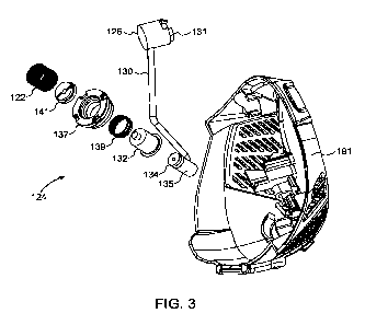
[0040] FIG. 3 is an exploded perspective view of a pneumatic pressure
adjustment
assembly for use with an exhalation valve of a facepiece in accordance with
some non-limiting
embodiments or aspects of the present disclosure;
[0041] FIG. 4A is side cross-sectional view of the pneumatic pressure
adjustment
assembly shown in FIG. 3 in a first mode of operation;
[0042] FIG. 4B is side cross-sectional view of the pneumatic pressure
adjustment assembly
shown in FIG. 3 in a second mode of operation;
7
CA 03194978 2023-03-10
WO 2022/056253 PCT/US2021/049852
[0043] FIGS. 5A-5C are front perspective views of an alignment mechanism
for aligning
a regulator with a facepiece during connection of the regulator to the
facepiece according to
some non-limiting embodiments or aspects of the present disclosure;
[0044] FIG. 5D is a top view of an alignment mechanism for aligning a
regulator with a
facepiece according to some non-limiting embodiments or aspects of the present
disclosure;
[0045] FIG. 6 is a top view of a facepiece safety device shown with a first
regulator;
[0046] FIG. 7 is a top view of a facepiece safety device shown with a
second regulator;
[0047] FIG. 8 is a detailed view of a connection interface between a
facepiece and a
regulator configured for dual mode operation;
[0048] FIG. 9 is a detailed view of a connection interface between a
facepiece and a
regulator configured for SCBA operation only;
[0049] FIG. 10A is front perspective view of a filter and filter clip
according to some non-
limiting embodiments or aspects of the present disclosure;
[0050] FIG. 10B is front perspective view of the filter clip shown in FIG.
10A without the
filter;
[0051] FIG. 10C is a front perspective view of the filter clip shown in
FIG. 10B in a folded
configuration; and
[0052] FIG. 10D is a front perspective view of the filter clip shown in
FIG. 10B removed
from a clip holder.
[0053] In FIGS. 1-10D, the same characters represent the same components
unless
otherwise indicated.
DETAILED DESCRIPTION
[0054] As used herein, the singular form of "a", "an", and "the" include
plural referents
unless the context clearly dictates otherwise.
[0055] Spatial or directional terms, such as "left", "right", "inner",
"outer", "above",
"below", and the like, relate to the invention as shown in the drawing figures
and are not to be
considered as limiting as the invention can assume various alternative
orientations.
[0056] All numbers used in the specification and claims are to be
understood as being
modified in all instances by the term "about". By "about" is meant within plus
or minus twenty-
five percent of the stated value. However, this should not be considered as
limiting to any
analysis of the values under the doctrine of equivalents.
[0057] Unless otherwise indicated, all ranges or ratios disclosed herein
are to be understood
to encompass the beginning and ending values and any and all subranges or
subratios subsumed
8
CA 03194978 2023-03-10
WO 2022/056253 PCT/US2021/049852
therein. For example, a stated range or ratio of "1 to 10" should be
considered to include any
and all subranges or subratios between (and inclusive of) the minimum value of
1 and the
maximum value of 10; that is, all subranges or subratios beginning with a
minimum value of 1
or more and ending with a maximum value of 10 or less. The ranges and/or
ratios disclosed
herein represent the average values over the specified range and/or ratio.
[0058] The terms "first", "second", and the like are not intended to refer
to any particular
order or chronology, but refer to different conditions, properties, or
elements.
[0059] All documents referred to herein are "incorporated by reference" in
their entirety.
[0060] The term "at least" is synonymous with "greater than or equal to".
[0061] As used herein, "at least one of" is synonymous with "one or more
of". For
example, the phrase "at least one of A, B, or C" means any one of A, B, or C,
or any
combination of any two or more of A, B, or C. For example, "at least one of A,
B, and C"
includes A alone; or B alone; or C alone; or A and B; or A and C; or B and C;
or all of A, B,
and C.
[0062] The term "includes" is synonymous with "comprises".
[0063] As used herein, the terms "parallel" or "substantially parallel"
mean a relative angle
as between two objects (if extended to theoretical intersection), such as
elongated objects and
including reference lines, that is from 00 to 5 , or from 0 to 3 , or from 0
to 2 , or from 0 to
1 , or from 0 to 0.5 , or from 0 to 0.25 , or from 0 to 0.1 , inclusive of
the recited values.
[0064] As used herein, the terms "perpendicular" or "substantially
perpendicular" mean a
relative angle as between two objects at their real or theoretical
intersection is from 85 to 90 ,
or from 87 to 90 , or from 88 to 90 , or from 89 to 90 , or from 89.5 to
90 , or from 89.75
to 90 , or from 89.9 to 90 , inclusive of the recited values.
[0065] The discussion of various examples or aspects may describe certain
features as
being "particularly" or "preferably" within certain limitations (e.g.,
"preferably", "more
preferably", or "even more preferably", within certain limitations). It is to
be understood that
the disclosure is not limited to these particular or preferred limitations but
encompasses the
entire scope of the various examples and aspects described herein.
[0066] The disclosure comprises, consists of, or consists essentially of,
the following
examples or aspects, in any combination. Various examples or aspects of the
disclosure are
illustrated in separate drawing figures. However, it is to be understood that
this is simply for
ease of illustration and discussion. In the practice of the disclosure, one or
more examples or
aspects shown in one drawing figure can be combined with one or more examples
or aspects
shown in one or more of the other drawing figures.
9
CA 03194978 2023-03-10
WO 2022/056253 PCT/US2021/049852
[0067] The present disclosure is directed to a breathing apparatus that is
operable between
at least two modes. In a first mode of operation, the breathing apparatus is
configured as an
SCBA, in which breathing air is delivered to a facepiece from a pressurized
air tank via an
airline connected to the facepiece and the pressurized air tank. In a second
mode of operation,
the breathing apparatus is configured as an APR, in which breathing air is
delivered to the
facepiece via an airline connected to a filter. In some non-limiting
embodiments or aspects
described herein, the devices, systems, or methods of the dual mode breathing
apparatus allow
a user to quickly, simply, and automatically switch between facepiece
exhalation modes
between the SCBA mode and the APR mode.
[0068] With reference to FIG. 1, a breathing apparatus 10 includes a
facemask 20 that is
configured for being selectively connected to a tank 200 containing
pressurized breathing gas
for delivery to the facemask 20 via a first airline 202 or a filter 300
configured for delivering
filtered ambient air to the facemask 20 via a second airline 302. As shown in
FIG. 2A, the
facemask 20 includes a facepiece 100 and a regulator 101 removably connectable
to the
facepiece 100. The facepiece 100 includes a first port 112 formed in a
regulator interface
portion of the facepiece 100 to place the facepiece 100 in fluid communication
with an outlet
of the regulator 101 via a mount or mounting interface so that air can be
supplied to the
facepiece 100 from the tank 200 when the breathing apparatus 10 is operated in
the SCBA
mode. In some non-limiting embodiments or aspects, the tank 200 is supported
on a backplate
204 that is connected to a harness (only portion of a shoulder strap 304 shown
in FIG. 1) worn
by a user. The tank 200 includes a tank actuation valve 206 to provide
pressurized breathing
gas to a first stage regulator 208, which then delivers the breathing gas to a
second stage
pressure regulator associated with the regulator 101 for a final pressure
reduction.
[0069] With reference to FIG. 2A, the facepiece 100 further includes a
second port 114
configured to be in fluid communication with the filter 300 via the second
airline 302 when the
breathing apparatus 10 is operated in the APR mode. In some embodiments or
aspects, the
second port 114 may be formed in a lens 116 of the facepiece 100. The lens 116
of the facepiece
100 is seated in a frame 117 having a seal 119 configured to form a seal with
the perimeter of
user's face. The general operation of an exemplary facepiece is described, for
example, in U.S.
Patent No. 8,256,420.
[0070] With reference to FIG. 2B, the facepiece 100 includes an exhalation
valve 250 for
exhausting the exhaled air from the interior of the facepiece 100. In some non-
limiting
embodiments or aspects, the exhalation valve 250 is biased against a valve
seat 252. The
exhalation valve 250 has a rigid contact member 254 and an elastomeric sealing
member 256
CA 03194978 2023-03-10
WO 2022/056253 PCT/US2021/049852
attached to the contact member 254 and extending beyond an outer edge or
perimeter of contact
member 254. The exhalation valve 250 is configured to move between a closed
position and
an open position in response to the user's respiration. The elastomeric
sealing member 256 is
configured to sealingly engage against the valve seat 252 when the exhalation
valve 250 is in
the closed position, such as during inhalation. During user exhalation, the
pressure created by
the user's exhaled breath urges the elastomefic sealing member 256 away from
the valve seat
252 to permit exiting of the exhaled air.
[0071] With continued reference to FIG. 2B, the facepiece 100 includes a
component
housing cover 191 that is removably connectable to the regulator interface
housing 199. The
component housing cover 191 may have a first connection component 193 that is
configured
for interacting with a second connection component 195 on the regulator
interface housing 199.
In some non-limiting embodiments or aspects, the first connection component
193 is
configured for releasably engaging the second connection component 195 to
enable removable
connection of the component housing cover 191 to the regulator interface
housing 199. The
first connection component 193 and the second connection component 195 may be
releasably
engaged with each other via mechanical or magnetic connection.
[0072] With continued reference to FIG. 2B, the regulator interface housing
199 has a
connection face 197 configured for engaging the corresponding connection face
201 on the
regulator 101. When connected, the regulator 101 is in mechanical and
pneumatic connection
with the regulator interface housing 199. In some non-limiting embodiments or
aspects, the
component housing cover 191 of the facemask 100 has a first pneumatic
connection 131 that
is configured for pneumatically engaging with a second pneumatic connection
129 on the
regulator 101. In this manner, the biasing force on the exhalation valve 250
may be controlled
depending on the pneumatic pressure between the first pneumatic connection 131
and the
second pneumatic connection 129. The second pneumatic connection 129 is in
fluid
communication with the outlet valve 136 of the regulator 101 (shown in FIG.
8).
[0073] With continued reference to FIG. 2B, the exhalation valve 250 is
biased in the
closed position against the valve seat 252 by a spring 122. With the dual mode
breathing
apparatus 10, the force with which the exhalation valve 250 is biased against
the valve seat 252
is adjustable to adjust the internal pressure within the facepiece 100. In
some non-limiting
embodiments or aspects, variation in the biasing force on the exhalation valve
250 is achieved
by a pneumatic pressure adjustment assembly 124 (shown in FIG. 3). Pneumatic
pressure,
such as the pressure of the breathing gas from the tank 200 delivered to the
regulator 101 via
the airline 202, is used as a communication link to provide an automatic
indication or signal to
11
CA 03194978 2023-03-10
WO 2022/056253 PCT/US2021/049852
the pneumatic pressure adjustment assembly 124 that the system is pressurized.
Moreover,
pneumatic pressure is also used to transmit force to the exhalation valve 250.
In alternative
non-limiting embodiments or aspects, other communication links and/or force
applicators can
be provided to automatically control the force applied to the exhalation valve
250 via the
pneumatic pressure adjustment assembly 124. For example, a mechanical link
(such as a
control cable or wire) can be provided between a pressure tank actuator and
the pneumatic
pressure adjustment assembly 124. Alternatively, wired or wireless
communication systems,
as known in the art, can be provided to, for example, actuate an
electromechanical actuation
system (for example, a solenoid in operative connection with a servo motor)
that adjusts the
force applied to the exhalation valve 250 via the pneumatic pressure
adjustment assembly 124.
[0074] The pneumatic pressure adjustment assembly 124 is configured for
varying the
working length of the spring 122 and thereby control the force needed to open
the exhalation
valve 250. The pneumatic communication link between the regulator 101 and the
exhalation
valve 250 in the facepiece 101 operates a mechanical piston assembly when
pressurized to
adjust the working length of the spring 122, which increases the exhalation
pressure of the
facepiece 100. When the mechanical piston assembly is depressurized, a return
spring returns
the piston to its resting position which adjusts the working length of the
spring 122 to decrease
the exhalation pressure of the facepiece 100. In this manner, adjustment of
the opening
pressure of the exhalation valve 250 between the SCBA mode and the APR mode is
made
automatically depending on whether pressurized air is delivered to the
regulator 101, such as
upon opening or closing of the air tank actuation valve 206. In that regard,
preferably no direct
or indirect manual adjustments, other than the opening or closing of the air
tank actuation valve
206, are required to switch the breathing apparatus 10 between the SCBA mode
and the APR
mode.
[0075] With reference to FIG. 3, the pressure adjustment assembly 124
includes an air inlet
126 into which pressurized air from the corresponding second pneumatic
connection 129 on
the regulator 101 (shown in FIGS. 2B and 8) is introduced when the breathing
apparatus 10 is
operated in the SCBA mode. The air inlet 126 defines the first pneumatic
connection 131 that
is configured for pneumatically interacting with a second pneumatic connection
129 (shown in
FIG. 2B) on the regulator 101 when the regulator 101 is connected to the
facepiece 100.
Pressurized air from the second pneumatic connection 129 is introduced into
the air inlet 126
and is guided into a piston chamber 128 (shown in FIG. 4A) via a fitting 135
at an end of a
conduit or pneumatic tube 130 in fluid connection with the air inlet 126. The
piston chamber
128 is defined between the fitting 135 and a piston 132 that is slidably
positioned on the fitting
12
CA 03194978 2023-03-10
WO 2022/056253 PCT/US2021/049852
135. A pressure seal is maintained between the piston 132 and the fitting 135,
for example, an
elastomeric seal, such as an 0-ring 134. A piston retainer 137 surrounds at
least a portion of
an outer surface of the piston 132. The piston retainer 137 is connected to
the component
housing cover 191 and is configured to delimit movement of the piston 132. A
return spring
139 is positioned between the piston 132 and the piston retainer 137. In some
non-limiting
embodiments or aspects, the return spring 139 is configured to compress when
the piston 132
is moved distally, such as when the piston chamber 128 is pressurized.
Conversely, the return
spring 139 is configured to urge the piston 132 in a proximal direction when
the piston chamber
128 is depressurized. A distal end of the piston 132 may have an engagement
pad 141
configured for engaging a proximal end of the spring 122.
[0076] Introduction of pressurized air into the piston chamber 128, such as
when the
regulator 101 is connected to the facepiece 100 to establish a pneumatic
connection between
the first pneumatic connection 131 and the second pneumatic connection 129,
causes the piston
132 to move distally toward the exhalation valve 250 (shown in FIG. 2B),
thereby compressing
the spring 122 to a first or stressed length corresponding to reduced working
length (FIG. 4A).
Such distal movement of the piston 132 also compresses the return spring 139.
The resultant
increase of force due to compression of the spring 122 upon the exhalation
valve 250 enables
the maintenance of an internal pressure within the facepiece 100 above ambient
pressure.
[0077] With reference to FIG. 4B, upon removal of air pressure from the
regulator 101,
such as by deactivation of the air tank actuator valve 206, disconnecting the
first airline 202,
or disconnecting the regulator 101 from the facepiece 100, pressure within the
piston chamber
128 is decreased and the return spring 139 causes the piston 132 to move in a
proximal direction
and away from the spring 122 and the exhalation valve 250 (shown in FIG. 2B).
The spring
122 is thereby allowed to relax or to return to a second length corresponding
to an increased
working length, decreasing the force upon the exhalation valve 250. The
reduced force upon
the exhalation valve 250 reduces the pressure within the facepiece 100 while
allowing the
exhalation valve 250 to maintain a seal against its seat.
[0078] With reference to FIGS. 5A-5C, an alignment mechanism 150 is shown
for aligning
the regulator 101 with the facepiece 100 according to some non-limiting
embodiments or
aspects of the present disclosure. The regulator 101 is removably connectable
to the facepiece
100 and the user must assure that a corresponding second pneumatic connection
129 (shown
in FIGS. 2B and 8) on the regulator 101 is properly aligned with a first
pneumatic connection
131 on the facepiece 100 (shown in FIG. 8) when connecting the regulator 101
to the facepiece
100. The regulator 101 and the facepiece 100 are further mechanically
connected to maintain
13
CA 03194978 2023-03-10
WO 2022/056253 PCT/US2021/049852
the fluid communication between the second pneumatic connection 129 in the
regulator 101
and the corresponding first pneumatic connection 131 in the facepiece 100. In
some non-
limiting embodiments or aspects, the regulator 101 and the facepiece 100 may
be connectable
by any mechanical connection, such as a bayonet connection, a spring-loaded
detent
connection, a press-in connection, or any other mechanism connection. One or
more locking
features may be provided on at least one of the regulator 101 and the
facepiece 100 for locking
the two components together after they have been aligned. In some situations,
it may be
difficult to ascertain whether a proper connection between the regulator 101
and the facepiece
100 has been made. If a proper connection is not made, the pneumatic fittings
in the
communication link between the facepiece 100 and the exhalation valve on the
regulator 101
may not be aligned properly, and the spring 122 may not be fully compressed to
its compressed
state.
[0079] With reference to FIGS. 5A-5B, the alignment mechanism 150 may
include at least
one pin 152 on one of the regulator 101 and the facepiece 100 and a
corresponding recess 154
on the other one of the regulator 101 and the facepiece 100. The pin 152 is
configured to be
received within the recess 154 when the regulator 101 and the facepiece 100
are in proper
alignment. The recess 154 may have an open end 156 configured for receiving
the pin 152 and
a closed end 158 opposite the open end 156 that acts as a stop surface for the
pin 152. In this
manner, the regulator 101 can be rotated relative to the facepiece 100, such
as in a direction of
arrow A in FIG. 5A, until the pin 152 is received through the open end 156 of
the recess 154
and in engagement with the closed end 158. This brings the regulator 101 in a
"staged" position
relative to the facepiece 100, wherein the ports on the regulator 101 and the
facepiece 100 are
aligned but not in fluid communication with each other. In this manner, the
alignment
mechanism 150 effectively "keys" or aligns the regulator 101 with the
facepiece 100 prior to
fully connecting the two components together.
[0080] With reference to FIG. 5B, once the regulator 101 is rotationally
aligned relative to
the facepiece 100 such that the pin 152 is received in the recess 154 until it
bottoms out against
the closed end 158 of the recess 154 (shown in FIG. 5A), the regulator 101 is
in rotational
alignment with the facepiece 100 and the pneumatic connections in the
facepiece 100 and the
regulator 101 (129, 131 shown in FIG. 8) are properly oriented for being
fluidly connected
with each other. The regulator 101 can be urged toward the facepiece 100 in a
direction of
arrow B to make a full connection therebetween. Such movement of the regulator
101 brings
the locking interface on the regulator 101 into engagement with a locking
interface on the
facepiece 100. For example, a detent 159 in the facepiece 100 may be
configured to receive a
14
CA 03194978 2023-03-10
WO 2022/056253 PCT/US2021/049852
movable locking element 157 on the regulator 101 to lock the regulator 101
with the facepiece
100 and make a pneumatic connection therebetween. When the regulator 101 is
fully
connected to the facepiece 100, such as shown in FIG. 5C, the pin 152 is
completely received
within the recess 154 and the movable locking element 157 is received within
the detent 159.
[0081] The alignment mechanism 150 makes the connection process between the
regulator
101 and the facepiece 100 faster and easier as it allows the user to fully
rotate the regulator 101
relative to the facepiece 100 into its proper alignment position with the
facepiece 100 prior to
making the connection with the facepiece 100. The alignment mechanism 150
further assures
a proper connection of the pneumatic connections in the facepiece 100 and the
regulator 101
(129, 131 shown in FIG. 8) when the regulator 101 is connected to the
facepiece 100 by
permitting physical connection between the regulator 101 and the facepiece 100
only when the
pneumatic connections 129, 131 are in full alignment. In this manner, the
pneumatic
connections 129, 131 will always deliver the appropriate pressure to the
exhalation valve 250
via the pneumatic pressure adjustment assembly 124.
[0082] In some non-limiting embodiments or aspects, such as shown in FIG.
5D, the
alignment mechanism 150 may be arranged such that it is substantially coaxial
with a
longitudinal axis L of the regulator 101. For example, the regulator 101 may
include the pin
152 at a central position of a body of the regulator 101 that is substantially
coaxial with the
longitudinal axis L.
[0083] With reference to FIG. 6, in some non-limiting embodiments or
aspects, a safety
device 160 is provided on the facepiece 100 and is configured for permitting
connection only
to a regulator 101 having a corresponding safety feature 161 that identifies
the regulator 101
as a correct regulator for connecting to the facepiece 100. For example, the
safety device 160
may be configured to permit connection of a regulator 101 that has the
appropriate pneumatic
connections to enable dual-mode use of the facepiece 100. The safety device
160 is further
configured to prevent connection of a regulator 101 not having the
corresponding safety feature
(see FIG. 7). In some embodiments or aspects, the safety device 160 may have a
protrusion
162 extending outwardly from a connection interface 165 on the facepiece 100.
The
corresponding safety feature 161 on the regulator 101 may be a slot 164
configured to receive
the protrusion 162 when the regulator 101 is fully connected to the facepiece
100. In this
manner, the protrusion 162 and the slot 164 effectively function as a "key"
arrangement that
permits connection of a regulator 101 having the appropriate slot 164, as
shown in FIG. 6, and
prevents connection of a regulator 101 not having the slot 164, as shown in
FIG. 7.
CA 03194978 2023-03-10
WO 2022/056253 PCT/US2021/049852
[0084] With continued reference to FIG. 6, the slot 164 may be provided
only on an
approved regulator 101 configured for dual mode use. The protrusion 162 is
shaped to be
received within the slot 164 when the regulator 101 is connected to the
facepiece 100. A
regulator 101 without the slot 164, such as shown in FIG. 7, would be
prevented from being
connected to the facepiece 100 due to the protrusion 162 on the facepiece 100
interfering with
the connection between the facepiece 100 and the regulator 101.
[0085] With reference to FIG. 8, the connection interface between the first
pneumatic
connection 131 in the facepiece 100 and the corresponding second pneumatic
connection 129
in the regulator 101 is shown in detail. The first pneumatic connection 131
has a post 133 that
is configured to engage the outlet valve 136 on the regulator 101. The outlet
valve 136 may be
biased in a closed position by a spring 138 and is moved to the open position
when urged by
the post 133 of the first pneumatic connection 131. In some non-limiting
embodiments or
aspects, the first pneumatic connection 131 in the facepiece 100 can be
replaced with a plug
170, shown in FIG. 9. The plug 170 may be configured to receive the
corresponding second
pneumatic connection 129 from the regulator 101 but not actuate the second
pneumatic
connection 129. In some non-limiting embodiments or aspects, the plug 170 may
be
monolithically formed with the facepiece 100 as a non-removable component. In
some non-
limiting embodiments or aspects, the plug 170 may removable from the facepiece
100 to allow
for installation of the first pneumatic connection 131 in the facepiece 100.
[0086] With the provision of the plug 170 shown in FIG. 9, the user has an
option for using
a facepiece 100 configured for dual mode operation (i.e., a facepiece 100
having the first
pneumatic connection 131) or a facepiece 100 configured for SCBA-only
operation (i.e., a
facepiece 100 having the plug 170), regardless of what regulator 101 is used
with the facepiece
100. If the user does not require switchable breathing modes, then the
facepiece 100 can be
configured with the plug 170, thereby reducing the cost of the facepiece 100.
If the user
requires a facepiece 100 with switchable modes (SCBA to APR) then the
facepiece 100 can be
configured with the first pneumatic connection 131 to enable actuation of the
exhalation valve
250.
[0087] With reference to FIG. 10A, the filter 300 is shown connected to a
shoulder strap
304 of a harness worn by the user via a clip 306. The filter 300 is configured
to filter the
ambient air using a filter element (not shown) and deliver the filtered air to
the facepiece 100
(shown in FIG. 1) via the second airline 302. By positioning the filter 300 on
the shoulder
strap 304, the filter 300 can be kept out of the user's way during use of the
breathing apparatus
(shown in FIG. 1). At least one of the filter 300 and the airline 302 may be
removably
16
CA 03194978 2023-03-10
WO 2022/056253 PCT/US2021/049852
attachable to the clip 306. In this manner, the filter 300 and the second
airline 302 may be
removed from the breathing apparatus 10 when the breathing apparatus 10 is
used in the SCBA
mode.
[0088] With reference to FIG. 10B, the clip 306 is shown without the filter
300 and the
airline 302 attached thereto. The clip 306 may have a retaining portion 310
configured for
receiving at least a portion of at least one of the filter 300 and the second
airline 302. In some
non-limiting embodiment or aspects, the retaining portion 310 may be
substantially U-shaped.
As shown in FIG. 10B, the retaining portion 310 may have a stem 311 with a
pair of arms 313
connected to the stem 311. The arms 313 may be configured for deflecting away
from each
other to permit insertion and removal of at least one of the filter 300 and
the airline 302. The
retaining portion 310 may be pivotally connected to a base 312. In this
manner, the retaining
portion 310 may be movable between a deployed position, in which at least one
of the filter
300 and the airline 302 can be connected to or removed from the retaining
portion 310 (shown
in FIG. 10B), and a stowed position for when the filter 300 and the airline
302 are disconnected
from the clip 306 (shown in FIG. 10C). The retaining portion 310 may be moved
from the
deployed position to the stowed position by rotating the retaining clip 306
relative to the base
312 about a pivot point 314 in a direction of arrow C shown in FIG. 10C. The
retaining portion
310 may be moved from the stowed position to the deployed position by rotating
the retaining
clip 306 relative to the base 312 about the pivot point 314 in a direction
opposite to the direction
of arrow C shown in FIG. 10C.
[0089] With reference to FIG. 10D, the clip 306 may be removably connected
to the
shoulder strap 304. In this manner, the clip 306 can be stowed when the
breathing apparatus
(shown in FIG. 1) is used in the SCBA mode. In some non-limiting embodiments
or
aspects, the shoulder strap 304 may have a receiver base 316 directly
integrated into the
material of the shoulder strap 304. The receiver base 316 may be configured
for removably
connecting to at least a portion of the clip 306, such as the base 312. In
some non-limiting
embodiments or aspects, the base 312 of the clip 306 may be removably
connectable to the
receiver base 316 on the shoulder strap 304 via a tongue-and-groove
arrangement, a clip, a
fastener, an adhesive, a magnet, any combination thereof, or any other
fastening mechanism.
To remove the clip 306 from the receiver base 316, the user may pull the base
312 of the clip
306 in a direction of arrow D in FIG. 10D to slide the base 312 away from the
receiver base
316.
[0090] The non-limiting embodiments or aspects of the present disclosure
have been
described in detail herein. However, it will be appreciated by those skilled
in the art that various
17
CA 03194978 2023-03-10
WO 2022/056253 PCT/US2021/049852
modifications and alternatives to the embodiments or aspects may be made
without departing
from the concepts disclosed in the foregoing description. Such modifications
are to be
considered as included within the following claims unless the claims, by their
language,
expressly state otherwise. Accordingly, the particular embodiments or aspects
described in
detail hereinabove are illustrative only and are not limiting as to the scope
of the disclosure,
which is to be given the full breadth of the appended claims and any and all
equivalents thereof
18