Note: Descriptions are shown in the official language in which they were submitted.
WO 2022/096077
PCT/EP2020/000188
- 1 -
Perforated acoustic panel, method of producing, and use of the same
Technical field
The invention relates to a perforated acoustic panel according to claim 1, a
method of
producing a perforated acoustic panel according to claim 12, and a use of a
perforated
acoustic panel according to claim 13.
Background
Room acoustics are an important factor that must be taken into consideration
during
building construction or renovation. Many public institutions such as
classrooms and
lecture halls, have strict regulations regarding room acoustics which must be
adhered to,
whilst areas such as offices and apartments require the noise management for
comfort or
even health, especially when open plan, minimalist furniture styles are
employed.
Additionally, room acoustics are a variable that need to be carefully
controlled in
environments such as theatres and music rooms to provide optimal conditions
for their
intended use.
A key factor used to indicate room acoustics is reverberation time.
Reverberation time
refers to the amount of time required for a sound to fade away inside an
enclosed space.
Sounds inside a room may reverberate when sound waves fail to be absorbed by
surfaces
they come into contact with, and instead of being absorbed are reflected off
said surfaces.
This reverberation time can be reduced by modifying surfaces such that sound
in a
relevant frequency range is absorbed more, and the reflections are hence
minimised. An
open-pored, acoustically absorbent material such as mineral fibre/wool,
polyester fibre,
PUR foam or felt may be utilized for this effect.
CA 03195010 2023- 4- 5 CONFIRMATION COPY
WO 2022/096077
PCT/EP2020/000188
- 2 -
For the improvement of room acoustics in the required environments, sound
absorbing
materials such as these may be utilized on wall, ceiling, and even floor
surfaces. These
sound absorbing materials may be sold with a finished surface such as mineral
fibre
ceilings, or the surface may be produced during the installation of these
materials, for
example on a perforated plasterboard ceiling which is attached to a suspension
system
of metal profiles or wooden slats with mineral wool backing. The sound
absorbing material
is typically located behind the perforated plasterboard.
Perforated surfaces of sound absorbing materials allow sound and/or air to
flow through
the material to increase the absorbing effect of the sound absorbing material
behind. The
perforations (holes) provide sound dampening properties that can be utilised
in the
acoustic management of a room. Said holes can provide acoustic dampening
effects to
the environment in which they are installed. These holes may have any one of a
variety
of shaped cross section, such as rectangular, square or circular. As the holes
in the
material, panel or board play a large part in providing the noise dampening
effects of the
material, hole distribution and size can thus be selected to provide the
required sound
dampening effects for a chosen environment.
An example of a perforated surface is the Knauf Cleaneo Akustikplatte
(acoustic board).
The sound dampening effect is achieved by the complete structure, including
perforated
plasterboards with a laminated film or fibre fleece on the side facing towards
the wall, and
with mineral wool in the cavity between plasterboard and wall. The structure
also includes
fastening means for attaching the boards to the wall.
Perforated sound absorbing panels, such as the Knauf Cleaneo Akustikplatte or
the Knauf
Cleaneo Acoustic linear panels, can be suspended from the a ceiling, whilst
mineral fibre
panels are often held in place via a grid-like railing structure which
surround the edges of
the individual panels. The sound absorbing material can be laid out in a
manner that
substantially conceals the edges and make the surface look like a plain wall.
The invention bases on the finding that a flexible printed circuit (FPC) can
be combined
with the perforated acoustic board to provide illumination in a production-
efficient and
cost-effective manner.
CA 03195010 2023- 4- 5
WO 2022/096077
PCT/EP2020/000188
- 3 -
An advantageous embodiment of the invention provides that the first and second
web
sections are arranged in a first plane and a central region of the web bead in
a second
plane. Preferably, the aforementioned central region can be formed straight.
The complicated and expensive integration of illumination in acoustic boards
according to
the prior art is overcome by a perforated acoustic panel according to claim 1,
the method
of producing a perforated acoustic panel according to claim 12 and the use of
a perforated
acoustic panel according to claim 13.
Summary
According to the invention, a perforated acoustic panel for mounting to a wall
and/or a
ceiling, the panel comprising a visible front side and a rear side opposite
the front side,
which is hidden when the panel is mounted. The perforated panel comprises at
least one,
preferably a plurality of perforations. The perforated panel is characterized
by a flexible
printed circuit layer, FPC, attached to its rear side, the FPC comprising a
plurality of LEDs,
each LED arranged to be positioned to emit light through a perforation of the
panel. The
FPC preferably is a paper FPC or a film FPC. LEDs (Light Emitting Diodes)
shall in the
context of this application also comprise OLEDs (Organic Light Emitting
Diodes) or any
other light source adapted to be integrated within a FPC.
In one embodiment, the panel comprises a gypsum body; and gypsum walls of the
perforation reflect (i.e. direct) light emitted from the LEDs through the
perforation.
Advantages include that the perforations in the acoustic panel naturally
provide a light
directing effect, in particular when the panel body is made of a light
reflecting material,
such as gypsum.
It has also been found that the light characteristics are modified by the
plaster walls of the
perforation, possibly due to reflection and absorption effects effectuated by
the gypsum
walls of the perforations.
The arrangement of the LEDs on the backside of the panel avoids disturbing
glare. The
comprehensive arrangement of LEDs eliminates shading effects.
CA 03195010 2023- 4- 5
WO 2022/096077
PCT/EP2020/000188
- 4 -
In one embodiment, the LEDs mounted on the FPC are positioned to emit light
through
each perforation of the panel.
In one embodiment, the LEDs mounted on the FPC are positioned to emit light
through
some perforations of the panel.
A LED may be arranged in each perforation, or may not be provided in each
perforation
but only in some, e.g. in a clustered arrangement or a regular arrangement
that regularly
spares individual perforations. The number of LEDs per perforation depends on
factors
such as desired illumination effect, strength of each LED, etc.
In one embodiment, the FPC is attached with an attachment comprising an
attachment
free margin around each perforation in order to facilitate sound wave
propagation through
the FPC. Preferably, the attachment free margin is between 3mm to 5mm.
An important factor for good sound absorbing characteristics of the acoustic
panel, is that
the perforation allows sound waves to penetrate through the panel into the
sound
absorbing material behind the panel. If the FPC is too tightly attached to the
panel, it will
restrict sound penetration. The FPC should therefore preferably be loosely
attached to the
rear side of the panel, preferably only at certain points, and/or having a
margin to the holes
in the panel, allowing the FPC to vibrate with the sound wave to allow the
sound to
propagate to the cavity with sound absorbing material behind the panel. In
order to further
increase sound penetration, the FPC is preferably perforated at least over the
panel
perforations not containing LEDs.
In one embodiment, the FPC is of less than 1.5 mm thickness, preferably less
than 1.2
mm thickness. For example, the substrate of the FPC (paper or film) can be
about 0.1 mm
thick, whereas the LEDs can have a height of about 0.8 mm. Substrate and LEDs
together
would have a thickness of about 0.9 mm. A reduced thickness of the FPC
facilitates sound
penetration and allows for lower mounting heights. Whilst paper is a
particularly well suited
material to be laminated onto a plasterboard other materials as a basic
material for the
FPC are also considered for forming a perforated acoustic panel according to
the
invention. In a preferred embodiment the FPC is a roll good, i.e. provided
from a roll with
a length of the FPC-material preferably being within 50 m to 150 m. The FPC-
material is
CA 03195010 2023- 4- 5
WO 2022/096077
PCT/EP2020/000188
- 5 -
cut to provide the particular FPC intended to be attached or laminated onto
the rear side
of the panel.
According to another embodiment, the FPC is a film FPC.
According to one embodiment, the plurality of LEDs are emitting light
perceived as white.
According to one embodiment, the LEDs are broad-spectrum LEDs.
According to one embodiment, the light emitted is perceived as white. This
light is emitted
by a combination of primary coloured, narrowband LEDs. The light intensity and
light
colour is adjustable by adjusting the intensity of each primary colour LED
independently
of the other primary colour LEDs.
Typically, illumination is preferably white. However, the panel may also be
constructed
with a certain coloured LED, or a combination of different coloured LEDs in
each
perforation, or in separate perforations. The LED intensity may be adjustable
in order to
adjust the intensity and/or the perceived colour of the illuminating panel.
The deficiency of the state of the art is further overcome by a method of
producing a
perforated acoustic panel according this disclosure.
In one embodiment, the method comprises the steps: arranging a FPC on the rear
side of
a perforated acoustic panel such that each of a plurality of LEDs arranged on
the FPC is
located over a perforation of the panel; and attaching the FPC to the panel
such as by
laminating, gluing or by aid of a connecting element such as for example by
nailing or
stapling. Other suitable means for attaching the FCP are possible.
Alternatively, the flange beads of one flange can be arranged along two, three
or more
lines, which are preferably parallel to each other. Those two, three or more
straight lines
can be oriented parallel to the longitudinal direction of the stud.
CA 03195010 2023- 4- 5
WO 2022/096077
PCT/EP2020/000188
- 6 -
Advantageously, paper FCPs usually can be contacted very easily via sidelong
contacting
zones that allow a connection to every (lateral) part of the ceiling taking
into account the
electric connections provided in the building.
The deficiency of the state of the art is further overcome by the use of a
perforated acoustic
panel as described in this disclosure to illuminate a room.
The benefits and advantages of the method and use described herein are equal
or similar
to the advantages of the herein described panel.
Figures
In the following, exemplary embodiments of the invention are described with
respect to
the figures, wherein
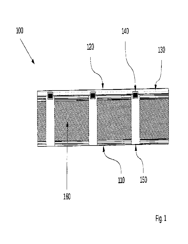
Fig. 1 outlines a cross section of an illuminating acoustic
panel;
Fig. 2 outlines an illuminating acoustic panel;
Fig. 3 outlines an illuminating acoustic panel with attachment
margins;
is Fig. 1 shows a cross section of an illuminating acoustic panel 100. The
panel comprises
a front side 110 of the panel, a rear side 120 of the panel, a flexible
printed circuit layer
(FPC; 130) including one or more Light Emitting Diodes (LEDs; 140). The panel
also
comprises perforations 150 and a panel core 160, preferably a gypsum core. The
acoustic
panel according to this example is an acoustic plasterboard. The walls of the
perforations
150 act as a light reflectors directing light through the perforations. This
results in
narrowed light beams compared to panels on which the LEDs are located on the
front side
of the panel. If the panel core 160 is a gypsum core the walls of the
perforations have
inherently a whitish colour and work as light reflectors without further
treatment. In case
the panel core 160 consists of another material, e.g. wood or else, it might
be advisable
to coat the perforation walls with a light reflecting material.
The FPC preferably is a paper FPC or a film FPC when used on acoustic
plasterboards.
When the FPC is a paper FPC, the paper is preferably less than 1.5mm thick,
and more
preferably less than 1.2mm thick. According to this example the paper
substrate of the
CA 03195010 2023- 4- 5
WO 2022/096077
PCT/EP2020/000188
- 7 -
FPC is about 0.1 mm thick, and the mounted LEDs have a height of about 0.8 mm.
Paper
substrate and LEDs together have a thickness of about 0.9 mm. Since the
acoustic panel
is a plasterboard the use of a paper FPC is especially beneficial because
plasterboards
usually have paper liners and the attachment is thus facilitated. However, if
the panel or
its casing is made of other materials it can be more favourable to use film
PFCs.
The panel 100 may be configured for mounting onto a wall and/or a ceiling (not
shown).
Sound absorbing material, such as mineral wool (not shown) may be arranged
behind the
panel (on the rear side 120 of the panel), when mounted. As shown, the FPC 130
is
attached to the rear side of the panel, and LEDs 140 of the FPC 130 are
arranged such
that their emitted light is directed through the perforations 150 of the panel
100.
Fig. 2 outlines an illuminating acoustic panel from the front side 110. The
FPC is attached
to the rear side 120 and is provided and arranged in such a way that the LEDs
140 are
arranged within perforations 150. Depending on the desired effect of the
illuminating
acoustic panel, LEDs may be located at only some, clustered, in every second,
or in each
perforation 150 of the panel.
Fig. 3 outlines an illuminating acoustic panel 100 from the rear side 120. The
FPC is
provided and positioned such that the LEDs 140 are arranged within the
perforations 150.
The FPC is attached to the panel at certain locations 310. Preferably, the
panel comprises
zo attachment free zones or margins 320 keeping a distance to the
perforations, in order to
allow for the FPC to vibrate and thus to prevent the reflection of sound
waves. The
attachment free margin 320 preferably comprises an area of 3 mm to 5 mm from
the edges
of each perforation 150, in order to facilitate sound wave to propagate
through the FPC.
The LEDs are preferably emitting light perceived as white, such as by using
broad-
spectrum white LEDs. The LEDs may also have different colours that can
individually be
adjusted in intensity, in order to have an adaptable illumination with respect
to intensity
and to perceived colour or along the panel, resulting in a colour pattern,
shape or image.
The illuminated acoustic panel can be used in wall or ceiling installations or
as an acoustic
sail/ sound absorber with added illumination.
CA 03195010 2023- 4- 5
WO 2022/096077
PCT/EP2020/000188
-8-
List of references
100 perforated acoustic panel
110 front side (of the panel)
120 rear side (of the panel)
130 flexible printed circuit layer (FPC)
lo 140 Light Emitting Diode (LED)
150 perforation of the panel
160 panel core
310 FPC attachment
320 attachment free margin
CA 03195010 2023- 4- 5