Note: Descriptions are shown in the official language in which they were submitted.
CA 03195236 2023-03-13
WO 2022/056462
PCT/US2021/050264
CRATE WITH RETRACTABLE WALL
BACKGROUND
[0001] Currently, some grocery items may be shipped to stores in metal crates
or
cardboard boxes. The grocery items must be unloaded and placed onto shelves
for the
customers to select and purchase. This requires labor for handling the grocery
items in the store.
[0002] The assignee of the present application has developed several
collapsible
containers with retractable front walls. The front wall of the container can
be reconfigured to a
retracted position while another identical container is stacked on it.
Retracting the front wall
provides access to the grocery items within the container without the need to
unload the grocery
items onto a shelf. A stack of such containers can be placed on a floor or in
a refrigerated area,
the front walls can be retracted, and the consumers can retrieve grocery items
directly from the
containers.
SUMMARY
[0003] An example container includes a wall extending upward from a base. The
wall
includes a frame and a first wall portion pivotably connected to the frame.
The wall further
includes a latch selectively connecting the first wall portion to the frame.
The latch is movable
vertically relative to the frame to selectively release the first wall portion
from the frame.
[0004] The latch may be slidably captured in the frame. A spring may bias the
latch
toward a latched position in which the latch connects the first wall portion
to the frame. The
spring may be formed integrally with the latch.
[0005] The container may also include a secondary latch and a cam. The
secondary
latch may be movable between a latched position preventing movement of the
first wall portion
relative to the frame and an unlatched position permitting movement of the
first wall portion
1
CA 03195236 2023-03-13
WO 2022/056462
PCT/US2021/050264
relative to the frame. Movement of the latch vertically causes the secondary
latch to move from
the latched position to the unlatched position via the cam.
[0006] The first wall portion may include a first horizontal wall portion and
arms
extending downward from the first horizontal wall portion when the first wall
portion is in a
deployed, closed position, the arms pivotably connected to the frame such that
the first wall
portion is pivotable between the deployed, closed position and a retracted,
open position.
[0007] The container may further include a second wall portion pivotably
connected to
the frame and movable between a deployed, closed position and a retracted,
open position.
[0008] The second wall portion may be connected to the first wall portion by
links
pivotably connected to the first wall portion and pivotably connected to the
second wall portion.
[0009] The second wall portion may be nested within the first wall portion
when the
first wall portion and the second wall portion are moved to the retracted,
open position.
[0010] The first wall portion and the second wall portion may lie flat against
an
upstanding flange of the base in the retracted, open position.
[0011] The second wall portion may include a second horizontal portion and
arms
extending downward from the second horizontal portion when the second wall
portion is in the
deployed, closed position, and such that the arms of the second wall portion
are received
between the arms of the first wall portion when the first wall portion and the
second wall
portion are in the retracted, open position.
[0012] The base may include an upstanding flange to which the wall is
pivotably
connected. The wall may be movable between an upright, use position and a
collapsed position
generally parallel to the base.
2
CA 03195236 2023-03-13
WO 2022/056462
PCT/US2021/050264
[0013] The container may further include a second wall perpendicular to the
first wall.
A wall latch may selectively connect the first wall to the second wall. The
second wall may
include a side flange extending parallel to the first wall. The wall latch may
be disposed in the
side flange. The wall latch may selectively secure the side flange to the
frame.
[0014] The first wall may be pivotably connected to the base about a first
axis, wherein
the second wall may be pivotably connected to the base about a second axis.
The first axis may
be further from the base than may be the second axis.
[0015] The first wall may be pivotably connected to the base about a first
axis and the
second wall may be pivotably connected to the base about a second axis. The
first axis may be
closer to the base than may be the second axis.
[0016] A secondary latch may be movable between a latched position preventing
movement of the second wall portion relative to the frame and an unlatched
position permitting
movement of the second wall portion relative to the frame. Movement of the
latch vertically
causes the secondary latch to move from the latched position to the unlatched
position via the
cam.
[0017] A container according to another example includes a wall extending
upward
from a base. The wall may include a frame and a first wall portion pivotably
connected to the
frame. The wall further may include a second wall portion pivotably connected
to the frame.
The first wall portion and the second wall portion may be movable between a
deployed, closed
position and a retracted, open position. The wall further may include a latch
movable vertically
relative to the frame and a secondary latch and a cam. The secondary latch may
be movable
between a latched position preventing movement of the second wall portion
relative to the
frame and an unlatched position permitting movement of the second wall portion
relative to
3
CA 03195236 2023-03-13
WO 2022/056462
PCT/US2021/050264
the frame. Movement of the latch vertically may cause the secondary latch to
move from the
latched position to the unlatched position via the cam.
[0018] The latch may be movable vertically between a latched position in which
the
latch secures the first wall portion to the frame and an unlatched position in
which the first wall
portion can pivot relative to the frame.
[0019] A container according to another example includes a wall extending
upward
from a base. The wall may include a frame and a first wall portion pivotably
connected to the
frame. The wall further may include a second wall portion pivotably connected
to the frame.
The first wall portion and the second wall portion may each be pivotable
between a deployed,
closed position and a retracted, open position. The second wall portion may be
nestably
received within the first wall portion when the first wall portion and the
second wall portion
are in the retracted, open position.
[0020] The first wall portion and the second wall portion may lie flat against
a lower
horizontal portion of the frame when the first wall portion and the second
wall portion are in
the retracted, open position.
[0021] The first wall portion and the second wall portion may each include a
horizontal
portion and a pair of arms extending from the horizontal portion. The pair of
arms of the second
wall portion may be received between the pair of arms of the first wall
portion when the first
wall portion and the second wall portion are in the retracted, open position.
[0022] The frame may include a lower horizontal portion and vertical portions
extending upward from opposite ends of the lower horizontal portion. The pair
of arms of the
first wall portion may be pivotably connected to the vertical portions of the
frame.
4
CA 03195236 2023-03-13
WO 2022/056462
PCT/US2021/050264
[0023] The pair of arms of the second wall portion may be pivotably connected
to the
vertical portions of the frame.
[0024] The container may further include a third wall portion having a
horizontal
portion and a pair of arms pivotably connected to the frame. The third wall
portion may be
nestably received within the second wall portion when the second wall portion
and third wall
portion are in the retracted, open position.
[0025] The horizontal portion of the second wall portion may be positioned
between
the arms of the first wall portion when the first wall portion and the second
wall portion are in
the deployed, closed position.
[0026] The horizontal portion of the third wall portion may be positioned
between the
arms of the second wall portion when the second wall portion and the third
wall portion are in
the deployed, closed position.
BRIEF DESCRIPTION OF THE DRAWINGS
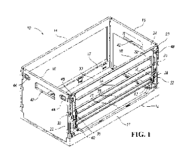
[0027] Figure 1 is a perspective view of a first example collapsible
container.
[0028] Figure 2 is an enlarged perspective view of one front corner of the
container of
Figure 1.
[0029] Figure 3 is a rear upper perspective view of the container of Figure 1.
[0030] Figure 4 is a front upper perspective view of the container of Figure
1.
[0031] Figure 5 is an end view of the container of Figure 1.
[0032] Figure 6 is a front view of the container of Figure 1.
[0033] Figure 7 is an enlarged view of the left end of the front of the
container of Figure
6.
[0034] Figure 8 is a section view of the container of Figure 1.
CA 03195236 2023-03-13
WO 2022/056462
PCT/US2021/050264
[0035] Figure 9 shows the container of Figure 1 with the latches released and
the front
wall beginning to be moved toward a retracted position.
[0036] Figure 10 is an enlarged view of one corner of Figure 9.
[0037] Figure 11 is a front view of the container of Figure 9.
[0038] Figure 12 is an enlarged view of one end of the front wall of the
container of
Figure 11.
[0039] Figure 13 is an end view of the container of Figure 9.
[0040] Figure 14 is a perspective view of the container of Figure 1 with the
front wall
in a second stage of being retracted.
[0041] Figure 15 is a front view of the container of Figure 14.
[0042] Figure 16 is an end view of the container of Figure 14.
[0043] Figure 17 is a perspective view of the container of Figure 1 with the
front wall
pivoted further toward the retracted position.
[0044] Figure 18 is an end view of the container of Figure 17.
[0045] Figure 19 is a perspective view of the container, partially broken
away, with the
front wall in the retracted position.
[0046] Figure 20 is an end view of the container of Figure 19, partially
broken away.
[0047] Figure 21 is an enlarged view of the section view of Figure 20.
[0048] Figure 22 shows a first step in collapsing the container, partially
broken away.
[0049] Figure 23 is an end view of the fully collapsed container.
[0050] Figure 24 is a top view of the collapsed container.
[0051] Figure 25 is a front view of the collapsed container.
[0052] Figure 26 is a perspective view of a third example collapsible
container.
6
CA 03195236 2023-03-13
WO 2022/056462
PCT/US2021/050264
[0053] Figure 27 is an enlarged perspective view of one front corner of the
container
of Figure 26.
[0054] Figure 28 is a front view of the container of Figure 26.
[0055] Figure 29 is an enlarged view of one front corner of the container of
Figure 28.
[0056] Figure 30 is an end view of the container of Figure 26.
[0057] Figure 31 is a section view of the container of Figure 26.
[0058] Figure 32 is a perspective view of the container of Figure 26 with the
front wall
beginning to be moved toward a retracted position.
[0059] Figure 33 is an enlarged view of one comer of Figure 32.
[0060] Figure 34 is an enlarged view of one end of the front wall of the
container of
Figure 32.
[0061] Figure 35 is an end view of the container with the front wall beginning
to be
retracted.
[0062] Figures 36, 37 and 38 show a second stage of the front wall being
retracted.
[0063] Figures 39 and 40 show the front wall of the container of Figure 35
pivoted
further toward the retracted position.
[0064] Figure 41 shows the container of Figure 26 with the front wall in the
retracted
position.
[0065] Figure 42 is a front view of the container of Figure 41.
[0066] Figure 43 is an end view of the container of Figure 41.
[0067] Figure 44 shows half of the container of Figure 26 (the other half is
broken away
for visibility) in the collapsed position.
[0068] Figure 45 shows the entire container of Figure 26 in the collapsed
position.
7
CA 03195236 2023-03-13
WO 2022/056462
PCT/US2021/050264
[0069] Figure 46 is a section view through the collapsed container of Figure
45.
[0070] Figure 47 is a front view of the collapsed container of Figure 45.
[0071] Figure 48 is a perspective view of a third example collapsible
container.
[0072] Figure 49 is a front view of the container of Figure 48.
[0073] Figure 50 shows the container of Figure 48 with the latch lifted
vertically to the
release position.
[0074] Figure 51 is a front view of the container of Figure 50.
[0075] Figure 52 is an enlarged view of one front comer of the container of
Figure 48,
with the latch in the down, latched position.
[0076] Figure 53 shows the corner of Figure 52 with the latch in the up,
released
position.
[0077] Figure 54 shows the collapsible container of Figure 48 with the front
wall
beginning to pivoted outward of the frame toward a retracted position.
[0078] Figure 55 is an enlarged view of one comer of Figure 54.
[0079] Figure 56 is a front view of the container of Figure 54.
[0080] Figure 57 is an end view of the container of Figure 54.
[0081] Figure 58 is a front view of the container of Figure 54 with the front
wall pivoted
further toward a retracted position.
[0082] Figure 59 is an end view of the container of Figure 58.
[0083] Figure 60 shows the container of Figure 48 with the front wall in the
retracted
position.
[0084] Figure 61 is a front view of the container with the front wall in the
retracted
position.
8
CA 03195236 2023-03-13
WO 2022/056462 PCT/US2021/050264
[0085] Figure 62 is an end view of the container of Figure 60.
[0086] Figure 63 shows the container of Figure 48 in a collapsed
configuration.
[0087] Figure 64 is a front view of the collapsed container of Figure 63.
[0088] Figure 65 is an end view of the collapsed container of Figure 63.
[0089] Figure 66 is a perspective view of a fourth example collapsible
container.
[0090] Figure 67 is an enlarged front view of one front corner of the
container of Figure
66, with the latch in the down, latched position.
[0091] Figure 68 is a perspective view of the corner of the container of
Figure 67.
[0092] Figure 69 shows the container of Figure 68 with the front wall pivoted
outward.
[0093] Figure 70 is an interior perspective view of the container of Figure
66.
[0094] Figure 71 is an enlarged view, partially broken away, of hinges of the
container
of Figure 70.
[0095] Figure 72 shows the container of Figure 71 with the rear wall being
pivoted
downward toward the base.
[0096] In Figures 73 and 74, the rear wall of Figure 72 has been pivoted
approximately
ninety degrees about the hinge.
[0097] In Figures 75 and 76, the rear wall lies substantially flat and flush
against the
base because the hinge pin has slid downward within the slot.
[0098] Figure 77 is a perspective view of a fifth example collapsible
container.
[0099] Figure 78 is an enlarged perspective view of one front corner of the
container
of Figure 77.
[00100] Figure 79 is a perspective view of the container of Figure 77 with
the
front wall moved toward a retracted position.
9
CA 03195236 2023-03-13
WO 2022/056462 PCT/US2021/050264
[00101] Figure 80 is an enlarged view of a portion of Figure 79.
[00102] Figure 81 shows the container of Figure 77 with the front wall in
the
retracted, open position.
[00103] Figure 82 shows the container of Figure 81, partially broken away.
DETAILED DESCRIPTION
[00104] A collapsible container 10 according to a first embodiment is shown
in
Figures 1-25. In Figure 1, the container 10 is in an upright, assembled
position. The container
includes a base 12. A rear wall 14, end walls 16 and a front wall 18 are
pivotably connected
at a periphery of the base 12. The base 12 includes upstanding flanges 17
projecting upward
from rear and front edges of the base 12 and formed integrally with the rest
of the base 12. The
end walls 16 are pivotably connected to end edges of the base 12 in a plane
lower than are the
front wall 18 and rear wall 14.
[00105] The front wall 18 includes a frame 20 pivotably connected to the
flange
17 at the front of the base 12. The frame 20 includes a lower horizontal
portion 21 and a pair
of upright vertical portions 22, together forming a U shape. The front wall 18
further includes
an upper (or "first") portion 24, a mid (or "second") portion 26 and a lower
(or "third") portion
28 within the frame 20. In Figure 1, the front wall 18 is in the closed
position with the upper
portion 24, mid portion 26 and lower portion 28 substantially closing the
large opening in the
frame 20.
[00106] The upper portion 24 includes a horizontal wall portion 30 and a
pair of
arms 32 extending from ends of the horizontal wall portion 30 in a direction
generally in the
plane of the horizontal wall portion 30 to form generally a U-shape (opening
downward in
Figure 1). In Figure 1, the upper portion 24 is selectively secured to the
frame 20 in an upper,
CA 03195236 2023-03-13
WO 2022/056462 PCT/US2021/050264
closed position by latches 48. The arms 32 of the upper portion 24 are
pivotably connected to
the vertical portions 22 of the frame 20.
[00107] The mid portion 26 includes a horizontal wall portion 34 and a pair
of
arms 36 extending from ends of the horizontal wall portion 34 in a direction
generally in the
plane of the horizontal wall portion 34 to form generally a U-shape (opening
downward in
Figure 1). The mid portion 26 is partially received between the arms 32 of the
upper portion
24. In this example, the horizontal wall portion 34 and upper portions of the
arms 36 are
received between lower portions of the arms 32 of the upper portion 24.
[00108] The lower portion 28 includes a horizontal wall portion 38 and a
pair of
arms 40 extending from ends of the horizontal wall portion 38 in a direction
generally in the
plane of the horizontal wall portion 38 to form generally a U-shape (opening
downward in
Figure 1). The lower portion 28 is partially received between the arms 36 of
the mid portion
26. In this example, the horizontal wall portion 38 and upper portions of the
arms 40 are
received between lower portions of the arms 36 of the mid portion 26.
[00109] In Figure 1, the walls 14, 16, 18 are in their upright, use
position. The
front wall 18 is in its deployed, closed position, with the horizontal wall
portions 30, 34, 38 of
the upper, mid and lower portions 24, 26, 28 extending across an upper
portion, a mid-portion,
and a lower portion respectively, of a large opening defined by the frame 20.
In the deployed,
closed position, the front wall 18 keeps objects, such as egg cartons, in the
container 10.
[00110] The end walls 16 are pivotably connected to end edges of the base
12.
Each end wall includes a handle opening 42 near an upper edge thereof. Each
end wall 16
includes a pair of latches 44 mounted therein for selectively securing the end
wall 16 to the rear
11
CA 03195236 2023-03-13
WO 2022/056462 PCT/US2021/050264
wall 14 and to the front wall 18 (more specifically to the frame 20). The
latches 44 are spring-
biased into recesses in the rear wall 14 and frame 20.
[00111] Figure 2 is an enlarged perspective view of one front corner of the
container 10 of Figure 1. The other front corner would be mirror image. The
latch 48 is shown
in more detail. The latch 48 is an elongated vertical member slidably mounted
for vertical
translation within a vertical channel molded into the vertical portion 22 of
the frame 20, and
secured to a plurality (three, in this example) of pins 50 received in
vertically elongated
apertures 52 (or slots) in the latch 48. The pins 50 are integrally molded
with the vertical
portions 22 of the frame 20. A lower spring 54 and an upper spring 56 are
integrally molded
with the latch 48 and bias the latch 48 downward relative to the frame 20. In
Figure 2, the latch
48 is shown in the downward, latched position. A locking projection 58
projects inward over a
portion of the arm 32 of the upper portion 24 to retain the upper portion 24
in the closed
position.
[00112] As can be seen in Figure 2, the arms 32 of the upper portion 24
each
have an elongated recess for receiving a link 60 pivotably securing the upper
portion 24 to the
mid portion 26. The arms 36 of the mid portion 26 each have an elongated
recess for receiving
a link 62 pivotably securing the mid portion 26 to the lower portion 28.
[00113] The upper portion 24 includes the horizontal wall portion 30 and an
upper horizontal rib 66 projecting outward from an upper edge thereof and a
lower horizontal
rib 68 projecting outward from a lower edge thereof. The upper horizontal rib
66 extends the
full length of the upper portion 24. The lower horizontal rib 68 does not
extend all the way to
the edges of the upper portion 24.
12
CA 03195236 2023-03-13
WO 2022/056462 PCT/US2021/050264
[00114] The mid portion 26 includes the horizontal wall portion 34 and an
upper
horizontal rib 70 projecting outward from an upper edge thereof and a lower
horizontal rib 72
projecting outward from a lower edge thereof. The upper horizontal rib 70
extends the full
length of the mid portion 26. The lower horizontal rib 72 does not extend all
the way to the
edges of the mid portion 26. The horizontal wall portion 34 of the mid portion
26 is disposed
between lower ends of the arms 32 of the upper portion 24.
[00115] The lower portion 28 includes the horizontal wall portion 38 and an
upper horizontal rib 74 projecting outward from an upper edge thereof and a
lower horizontal
rib 76 projecting outward from a lower edge thereof. The upper horizontal rib
74 extends the
full length of the lower portion 28. The lower horizontal rib 76 extends all
the way to the edges
of the lower portion 28. The horizontal wall portion 38 of the lower portion
28 is positioned
partially between the arms 36 of the mid portion 26.
[00116] Figure 3 is a rear upper perspective view of the container 10.
Double-
axis hinges 78 connect the frame 20 to the upstanding flange 17 of the base
12. These hinges
reduce the collapsed height of the container 10. Figure 4 is a front upper
perspective view of
the container 10. Double-axis hinges 80 connect the rear wall 14 to the
upstanding flange 17
of the base 12. Again, these hinges reduce the collapsed height of the
container 10.
[00117] Figure 5 is an end view of the container 10. Each end wall 16
includes
the handle opening 42 near an upper edge thereof. Each end wall 16 -includes
the pair of latches
44 mounted therein for selectively securing the end wall 16 to the rear wall
14 and to the front
wall 18 (more specifically to the frame 20). The latches 44 are spring biased
into recesses in
the rear wall 14 and frame 20. The latches 44 can be released by moving them
toward one
another. Then the end wall 16 can be pivoted inward onto the base 12.
13
CA 03195236 2023-03-13
WO 2022/056462 PCT/US2021/050264
[00118] Figure 6 is a front view of the container 10. Figure 7 is an
enlarged view
of the left end of the front of the container 10 of Figure 6. Again, the right
end would be mirror
image. The latch 48 is mounted to slide vertically relative to the frame 20. A
secondary latch
82 is also slidably mounted to the frame 20. The secondary latch 82 is mounted
to slide
horizontally relative to the frame 20 (i.e. right and left in Figure 7). In
Figure 7, the secondary
latch 82 is shown in the latched position (to the right) where it retains the
mid portion 26 and
lower portion 28 in the closed position. The secondary latch 82 includes an
upper locking
member 83 positioned outward of the arm 36 of the mid portion 26. The
secondary latch 82
also includes a lower locking member 85 positioned outward of the arm 40 of
the lower portion
28.
[00119] The secondary latch 82 is slidably mounted to pins 84 that are
integrally
molded with the vertical portions 22 of the frame 20 and that are received in
horizontally-
elongated apertures 86 in the secondary latch 82. The secondary latch 82 is
moved horizontally
(left and right in Figure 7) by a cam between the secondary latch 82 and the
latch 48. The cam
comprises a pin 88 integrally molded with the latch 48 and projecting rearward
into an
elongated aperture 90 in the secondary latch 82. The elongated aperture 90
extends at an angle
upward and inward, such that when the user slides the latch 48 upward, the cam
causes the
secondary latch 82 to move outward (left in Figure 7). The cam could
alternatively have the
pins formed on the secondary latch 82 and have the pins received in an angled
slot on the latch
48.
[00120] The arms 36 of the mid portion 26 are between the arms 32 of the
upper
portion 24. The arms 40 of the lower portion 28 are between the arms 36 of the
mid portion 26.
The arms 32, 36, 40 are configured, by virtue of their length and the position
at which they are
14
CA 03195236 2023-03-13
WO 2022/056462 PCT/US2021/050264
hingeably connected to the frame 20, such that the horizontal wall portions
30, 34, 38 can nest
when they are in the retracted, open position (discussed below).
[00121] Figure 8 is a section view of the container 10. The upper portion
24
includes the horizontal wall portion 30 and the upper horizontal rib 66
projecting outward from
an upper edge thereof and the lower horizontal rib 68 projecting outward from
a lower edge
thereof. The mid portion 26 includes the horizontal wall portion 34 and the
upper horizontal
rib 70 projecting outward from the upper edge thereof and the lower horizontal
rib 72 projecting
outward from the lower edge thereof. The lower portion 28 includes the
horizontal wall portion
38 and the upper horizontal rib 74 projecting outward from the upper edge
thereof and the
lower horizontal rib 76 projecting outward from the lower edge thereof. As can
be seen, the
horizontal wall portion 30 of the upper portion 24 is taller (i.e. has a
greater vertical dimension)
than the horizontal wall portion 34 of the mid portion 26, which is taller
than the horizontal
wall portion 38 of the lower portion 28.
[00122] In Figure 9, the latches 48 have been slid upward relative to the
frame
20, also causing the secondary latches 82 to slide outward (away from each
other). This permits
the upper portion 24, mid portion 26, and lower portion 28 to pivot outward of
the frame 20.
The links 60, 62 also pivot outward so that the upper portion 24, mid portion
26 and lower
portion 28 all pivot and move together. The user can lift and lower all three
portions 24, 26, 28
by moving any one of them. Figure 10 is an enlarged view of one comer of
Figure 9. The links
60, 62 pivot outward of the recesses in the arms 32, 36.
[00123] Figure 11 is a front view of the container 10 of Figure 9. Figure
12 is an
enlarged view of one end of the front wall 18 of the container 10 of Figure
11. The latch 48 has
been slid upward relative to the frame 20 to an unlatched position, also
causing the secondary
CA 03195236 2023-03-13
WO 2022/056462 PCT/US2021/050264
latch 82 to slide outward (to the left in Figure 12) to an unlatched position.
As shown, the
locking projection 58 releases the arm 32 of the upper portion 24. The pin 88
slides to the top
of the angled aperture 90 in the secondary latch 82, causing the secondary
latch 82 to move
outward (to the left in Figure 12). This moves the upper locking member 83 out
from in front
of the arm 36 and moves the lower locking member 85 out from in front of the
arm 40. As
shown, the upper portion 24, mid portion 26, and lower portion 28 can start to
pivot outward
of the frame 20. The upper spring 56 and lower spring 54 are elastically
deformed, and bias the
latch 48 downward back toward the latched position. Figure 13 is an end view
of the container
with the front wall 18 beginning to be retracted.
[00124] Figures 14, 15 and 16 show a second stage of the front wall 18
being
retracted. Figures 17 and 18 show the upper portion 24, mid portion 26, and
lower portion 28
pivoted further toward the retracted position.
[00125] Figure 19 is a section view of the container 10 with the front wall
18 in
the retracted position. The upper portion 24, mid portion 26 and lower portion
28 are nested
adjacent the upstanding flange 17 and the horizontal portion 21 of the frame
20. The arms 36
of the mid portion 26 are inward of the arms 32 of the upper portion 24. The
arms 40 of the
lower portion 28 are inward of the mid portion 26. In the retracted position,
all of the arms 32,
36, 40 extend upward from the respective wall portions 30, 34, 38. Figure 21
is an enlarged
view of the section view of Figure 20.
[00126] As shown in Figure 21, horizontal wall portion 34 of the mid
portion 26
is nested within the horizontal wall portion 30 of the upper portion 24. The
horizontal wall
portion 38 of the lower portion 28 is nested within the horizontal wall
portion 34 of the mid
16
CA 03195236 2023-03-13
WO 2022/056462 PCT/US2021/050264
portion 26. In this manner, the upper portion 24, mid portion 26 and lower
portion 28 can lie
flat against the upstanding flange 17 and frame 20.
[00127] .. More particularly, the horizontal wall portion 34 of the mid
portion 26
is nested between the upper horizontal rib 66 and lower horizontal rib 68 of
the upper portion
24. The horizontal wall portion 30 is outward of the horizontal wall portion
34. The horizontal
wall portion 38 of the lower portion 28 is nested between the upper horizontal
rib 70 and the
lower horizontal rib 72 of the mid portion 26. The horizontal wall portion 34
is outward of the
horizontal wall portion 38.
[00128] Figure 22 shows a first step in collapsing the container 10. The
end walls
16 (one shown) are collapsed onto the base 12 after releasing the latches 44.
The rear wall 14
and front wall 18 can then be collapsed onto the end walls 16, as shown in
Figure 23. Figure
24 is a top view of the collapsed container 10. Figure 25 is a front view of
the collapsed
container 10.
[00129] A collapsible container 110 according to a second embodiment is
shown
in Figure 26. The container 110 functions similarly to the container 10 of
Figures 1-25 except
as otherwise shown or described. Primarily, the container 110 is collapsed by
first folding the
rear wall 114 and front wall 118 onto the base 112 (in either order), rather
than the end walls
16 first as in the previous container 10. This permits the front wall 118 to
have a taller vertical
opening because the frame 120 is hinged closer to the base 112.
[00130] In Figure 26, the container 110 is in an upright, assembled
position. The
container 110 includes a base 112. A rear wall 114, end walls 116 and a front
wall 118 are
pivotably connected at a periphery of the base 112. The base 112 includes
upstanding flanges
119 projecting upward from end edges of the base 112 and formed integrally
with the rest of
17
CA 03195236 2023-03-13
WO 2022/056462 PCT/US2021/050264
the base 112. The front wall 118 and rear wall 114 are pivotably connected to
the base 112
about axes lower than are the end walls 116.
[00131] .. The front wall 118 includes a frame 120 pivotably connected at the
front
of the base 112. The frame 120 includes a lower horizontal portion 121 and a
pair of upright
vertical portions 122, together forming a U shape. The front wall 118 further
includes an upper
(or "first") portion 124, a mid (or "second") portion 126 and a lower (or
"third") portion 128
within the frame 120. In Figure 26, the front wall 118 is in the closed
position with the upper
portion 124, mid portion 126 and lower portion 128 substantially closing the
large opening in
the frame 120.
[00132] The upper portion 124 includes a horizontal wall portion 130 and a
pair
of arms 132 extending from ends of the horizontal wall portion 130 in a
direction generally in
the plane of the horizontal wall portion 130 to form generally a U-shape
(opening downward
in Figure 26). In Figure 26, the upper portion 124 is selectively secured to
the frame 120 in an
upper, closed position by latches 148. The arms 132 of the upper portion 124
are pivotably
connected to the vertical portions 122 of the frame 120.
[00133] The mid portion 126 includes a horizontal wall portion 134 and a
pair of
arms 136 extending from ends of the horizontal wall portion 134 in a direction
generally in the
plane of the horizontal wall portion 134 to form generally a U-shape (opening
downward in
Figure 26). The mid portion 126 is partially received between the arms 132 of
the upper portion
124. In this example, the horizontal wall portion 134 and upper portions of
the arms 136 are
received between lower portions of the arms 132 of the upper portion 124.
[00134] The lower portion 128 includes a horizontal wall portion 138 and a
pair
of arms 140 extending from ends of the horizontal wall portion 138 in a
direction generally in
18
CA 03195236 2023-03-13
WO 2022/056462 PCT/US2021/050264
the plane of the horizontal wall portion 138 to form generally a U-shape
(opening downward
in Figure 26). The lower portion 128 is partially received between the arms
136 of the mid
portion 126. In this example, the horizontal wall portion 138 and upper
portions of the arms
140 are received between lower portions of the arms 136 of the mid portion
126.
[00135] In Figure 26, the walls 114, 116, 118 are in their upright, use
position.
The front wall 118 is in its deployed, closed position, with the horizontal
wall portions 130,
134, 138 of the upper, mid and lower portions 124, 126, 128 extending across
an upper portion,
a mid-portion, and a lower portion respectively, of a large opening defined by
the frame 120.
In the deployed, closed position, the front wall 118 keeps objects, such as
egg cartons, in the
container 110.
[00136] The end walls 116 are pivotably connected to end edges of the base
112.
Each end wall includes a handle opening 142 near an upper edge thereof. Each
end wall 116
includes a pair of opposed side flanges 123 projecting perpendicularly from
the end wall 116.
Each side flange 123 includes latch 144 mounted therein for selectively
securing the end wall
116 to the rear wall 114 and to the front wall 118 (more specifically to the
frame 120). Each
side flange 123 also includes an interlocking portion that interlocks with a
complementary
interlocking portion on the rear wall 114 or the front wall 118.
[00137] Figure 27 is an enlarged perspective view of one front corner of
the
container 110 of Figure 26. Figure 28 is a front view of the container 110.
[00138] Figure 29 is an enlarged view of one front corner of the container
110 of
Figure 28. The other front corner would be mirror image. The latch 148 is
shown in more detail.
The latch 148 is an elongated vertical member slidably mounted for vertical
translation within
a vertical channel molded into the vertical portion 122 of the frame 120, and
secured to a
19
CA 03195236 2023-03-13
WO 2022/056462 PCT/US2021/050264
plurality (three, in this example) of pins 150 received in vertically
elongated apertures 152 (or
slots) in the latch 148. The pins 150 are integrally molded with the vertical
portions 122 of the
frame 120. A lower spring 154 is integrally molded with the latch 148 and
biases the latch 148
downward relative to the frame 120. In Figure 29, the latch 148 is shown in
the downward,
latched position. A locking projection 158 projects inward over a portion of
the arm 132 of the
upper portion 124 to retain the upper portion 124 in the closed position.
[00139] As can be seen in Figure 29, the arms 132 of the upper portion 124
each
have an elongated recess for receiving a link 160 pivotably securing the upper
portion 124 to
the mid portion 126. The arms 136 of the mid portion 126 each have an
elongated recess for
receiving a link 162 pivotably securing the mid portion 126 to the lower
portion 128.
[00140] The vertical portions 122 of the frame 120 are moved inward
slightly
compared to the previous embodiment to accommodate the latches 144 in the end
walls 116
and the fact that the front wall 118 is between the end walls 116 (in Figure
1, the end walls 16
are between the rear wall 14 and front wall 18).
[00141] The upper portion 124 includes the horizontal wall portion 130 and
an
upper horizontal rib projecting outward from an upper edge thereof and a lower
horizontal rib
projecting outward from a lower edge thereof. The upper horizontal rib extends
the full length
of the upper portion 124. The lower horizontal rib does not extend all the way
to the edges of
the upper portion 124.
[00142] .. The mid portion 126 includes the horizontal wall portion 134 and an
upper horizontal rib projecting outward from an upper edge thereof and a lower
horizontal rib
projecting outward from a lower edge thereof. The upper horizontal rib extends
the full length
CA 03195236 2023-03-13
WO 2022/056462 PCT/US2021/050264
of the mid portion 126. The lower horizontal rib does not extend all the way
to the edges of the
mid portion 126.
[00143] The lower portion 128 includes the horizontal wall portion 138 and
an
upper horizontal rib projecting outward from an upper edge thereof and a lower
horizontal rib
projecting outward from a lower edge thereof. The upper horizontal rib extends
the full length
of the lower portion 128. The lower horizontal rib extends all the way to the
edges of the lower
portion 128.
[00144] A secondary latch 182 is also slidably mounted to the frame 120.
The
secondary latch 182 is mounted to slide horizontally relative to the frame 120
(i.e. right and
left in Figure 29). In Figure 29, the secondary latch 182 is shown in the
latched position (to the
right) where it retains the mid portion 126 and lower portion 128 in the
closed position. The
secondary latch 182 includes an upper locking member 183 positioned outward of
the arm 136
of the mid portion 126. The secondary latch 182 also includes a lower locking
member 185
positioned outward of the arm 140 of the lower portion 128.
[00145] The secondary latch 182 is slidably mounted to pins 184 that are
integrally molded with the vertical portions 122 of the frame 120 and that are
received in
horizontally-elongated apertures 186 in the secondary latch 182. The secondary
latch 182 is
moved horizontally (left and right in Figure 29) by a cam between the
secondary latch 182 and
the latch 148. The cam comprises a pin 188 integrally molded with the latch
148 and projecting
rearward into an elongated aperture 190 in the secondary latch 182. The
elongated aperture 190
extends at an angle upward and inward, such that when the user slides the
latch 148 upward,
the cam causes the secondary latch 182 to move outward (left in Figure 29).
21
CA 03195236 2023-03-13
WO 2022/056462 PCT/US2021/050264
[00146] .. Figure 30 is an end view of the container 110. Each end wall 116
includes the handle opening 142 near an upper edge thereof. Each end wall 116
is pivotably
connected to the upstanding flanges 119.
[00147] Figure 31 is a section view of the container 110. The upper portion
124
includes the horizontal wall portion 130 and the upper horizontal rib
projecting outward from
an upper edge thereof and the lower horizontal rib projecting outward from a
lower edge
thereof. The mid portion 126 includes the horizontal wall portion 134 and the
upper horizontal
rib projecting outward from the upper edge thereof and the lower horizontal
rib projecting
outward from the lower edge thereof. The lower portion 128 includes the
horizontal wall
portion 138 and the upper horizontal rib projecting outward from the upper
edge thereof and
the lower horizontal rib projecting outward from the lower edge thereof. As
can be seen, the
horizontal wall portion 130 of the upper portion 124 is taller than the
horizontal wall portion
134 of the mid portion 126, which is taller than the horizontal wall portion
138 of the lower
portion 128.
[00148] .. In Figure 32, the latches 148 have been slid upward relative to the
frame
120, also causing the secondary latches 182 to slide outward (away from each
other). This
permits the upper portion 124, mid portion 126, and lower portion 128 to pivot
outward of the
frame 120. The links 160, 162 also pivot outward so that the upper portion
124, mid portion
126 and lower portion 128 all pivot and move together. The user can lift and
lower all three
portions 124, 126, 128 by moving any one of them. Figure 33 is an enlarged
view of one comer
of Figure 32. The links 160, 162 pivot outward of the recesses in the arms
132, 136.
[00149] Figure 34 is an enlarged view of one end of the front wall 118 of
the
container 110 of Figure 32. The other end would be mirror image. The latch 148
has been slid
22
CA 03195236 2023-03-13
WO 2022/056462 PCT/US2021/050264
upward relative to the frame 120 to an unlatched position, also causing the
secondary latch 182
to slide outward (to the left in Figure 34) to an unlatched position. As
shown, the locking
projection 158 releases the arm 132 of the upper portion 124. The pin 188
slides to the top of
the angled aperture 190 in the secondary latch 182, causing the secondary
latch 182 to move
outward (to the left in Figure 34). This moves the upper locking member 183
out from in front
of the arm 136 and moves the lower locking member 185 out from in front of the
arm 140. As
shown, the upper portion 124, mid portion 126, and lower portion 128 can start
to pivot outward
of the frame 120. The lower spring 154 is elastically deformed, and biases the
latch 148
downward back toward the latched position. Figure 35 is an end view of the
container 110 with
the front wall 118 beginning to be retracted.
[00150] Figures 36, 37 and 38- show a second stage of the front wall 118
being
retracted. Figures 39 and 40 show the upper portion 124, mid portion 126, and
lower portion
128 pivoted further toward the retracted position.
[00151] Figure 41 shows the container 110 with the front wall 118 in the
retracted position. The upper portion 124, mid portion 126 and lower portion
128 are nested
(as before) adjacent the horizontal portion 121 of the frame 120. The arms 136
of the mid
portion 126 are inward of the arms 132 of the upper portion 124. The arms 140
of the lower
portion 128 are inward of the mid portion 126.
[00152] As shown in Figures 42 and 43, horizontal wall portion 134 of the
mid
portion 126 is nested within the horizontal wall portion 130 of the upper
portion 124. The
horizontal wall portion 138 of the lower portion 128 is nested within the
horizontal wall portion
134 of the mid portion 126. In this manner, the upper portion 124, mid portion
126 and lower
portion 128 can lie flat against the frame 120.
23
CA 03195236 2023-03-13
WO 2022/056462 PCT/US2021/050264
[00153] .. Figure 44 shows half of the container 110 (the other half is broken
away
for visibility) in the collapsed position. The rear wall 114 and front wall
118 are collapsed onto
the base 112 (in either order) after releasing the latches 144. The end walls
116 are collapsed
onto the rear wall 114 and front wall 118. Figure 45 shows the entire
container 110 in the
collapsed position. Figure 46 is a section view through the collapsed
container 110. Figure 47
is a front view of the collapsed container 110. Note that the end walls 116
collapse to a height
lower than the upstanding flanges 119, so the collapsed container 110 has a
significantly
reduced volume for very efficient storage and transport when empty.
[00154] A collapsible container 210 according to a third embodiment is
shown
in Figure 48, In Figure 48, the container 210 is in an upright, assembled
position. The container
210 includes a base 212. A rear wall 214, end walls 216 and a front wall 218
are pivotably
connected at a periphery of the base 212. The base 212 includes upstanding
flanges 217
projecting upward from rear and front edges of the base 212 and formed
integrally with the rest
of the base 212. In this embodiment, once again the end walls 216 are
configured to fold onto
the base 212 prior to the rear wall 214 and front wall 218. Thus the end walls
216 are pivotably
connected to the base 212 lower than are the rear wall 214 and front wall 218,
and the end walls
216 are between the rear wall 214 and front wall 218.
[00155] The front wall 218 includes a frame 220 pivotably connected to the
flange 217 at the front of the base 212. The frame 220 includes a lower
horizontal portion 221
and a pair of upright vertical portions 222, together forming a U shape. The
front wall 218
further includes an upper (or "first") portion 224, a mid (or "second")
portion 226 and a lower
(or "third") portion 228 within the frame 220. In Figure 48, the front wall
218 is in the closed
24
CA 03195236 2023-03-13
WO 2022/056462 PCT/US2021/050264
position with the upper portion 224, mid portion 226 and lower portion 228
substantially
closing the large opening in the frame 220.
[00156] The upper portion 224 includes a horizontal wall portion 230 and a
pair
of arms 232 extending from ends of the horizontal wall portion 230 in a
direction generally in
the plane of the horizontal wall portion 230 to form generally a U-shape
(opening downward
in Figure 48). In Figure 48, the upper portion 224 is selectively secured to
the frame 220 in an
upper, closed position by latches 248. The arms 232 of the upper portion 224
are pivotably
connected to the vertical portions 222 of the frame 220.
[00157] The mid portion 226 includes a horizontal wall portion 234 and a
pair of
arms 236 extending from ends of the horizontal wall portion 234 in a direction
generally in the
plane of the horizontal wall portion 234 to form generally a U-shape (opening
downward in
Figure 48). The mid portion 226 is partially received between the arms 232 of
the upper portion
224. In this example, the horizontal wall portion 234 and upper portions of
the arms 236 are
received between lower portions of the arms 232 of the upper portion 224.
[00158] The lower portion 228 includes a horizontal wall portion 238 and a
pair
of arms 240 extending from ends of the horizontal wall portion 238 in a
direction generally in
the plane of the horizontal wall portion 238 to form generally a U-shape
(opening downward
in Figure 48). The lower portion 228 is partially received between the arms
236 of the mid
portion 226. In this example, the horizontal wall portion 238 and upper
portions of the arms
240 are received between lower portions of the arms 236 of the mid portion
226.
[00159] In Figure 48, the walls 214, 216, 218 are in their upright, use
position.
The front wall 218 is in its deployed, closed position, with the horizontal
wall portions 230,
234, 238 of the upper, mid and lower portions 224, 226, 228 extending across
an upper portion,
CA 03195236 2023-03-13
WO 2022/056462 PCT/US2021/050264
a mid-portion, and a lower portion respectively, of a large opening defined by
the frame 220.
In the deployed, closed position, the front wall 218 keeps objects, such as
egg cartons, in the
container 210.
[00160] The end walls 216 are pivotably connected to end edges of the base
212.
Each end wall includes a handle opening 242 near an upper edge thereof. Each
end wall 216
includes a pair of latches 244 mounted therein for selectively securing the
end wall 216 to the
rear wall 214 and to the front wall 218 (more specifically to the frame 220).
The latches 244
can be released by lifting a bar 245 below the handle opening 242 that is
spring-biased
downward.
[00161] .. Figure 49 is a front view of the container 210 of Figure 48. The
front
wall 218 is in its deployed, closed position, with the horizontal wall
portions 230, 234, 238 of
the upper, mid and lower portions 224, 226, 228 extending across an upper
portion, a mid-
portion, and a lower portion respectively, of a large opening defined by the
frame 220. In the
deployed, closed position, the front wall 218 keeps objects, such as egg
cartons, in the container
210.
[00162] Figure 50 shows the container 210 of Figure 48 with the latch 248
lifted
vertically to the release position. Figure 51 is a front view of the container
210 of Figure 50.
[00163] Figure 52 is an enlarged view of one front corner of the container
210 of
Figure 48, with the latch in the down, latched position. Figure 53 is an
enlarged view of the
corner of Figure 48 with the latch in the up, released position. The other
front corner would be
mirror image. The latch 248 is shown in more detail. The latch 248 is an
elongated vertical
member slidably mounted for vertical translation within a vertical channel
molded into the
vertical portion 222 of the frame 220, and secured to a plurality (three, in
this example) of pins
26
CA 03195236 2023-03-13
WO 2022/056462 PCT/US2021/050264
250 received in vertically elongated apertures 252 (or slots) in the latch
248. The pins 250 are
integrally molded with the vertical portions 222 of the frame 220. A pair of
lower springs 254
are integrally molded with the latch 248 and bias the latch 248 downward
relative to the frame
220. In Figure 52, the latch 248 is shown in the downward, latched position.
[00164] As can be seen in Figure 52, the arms 232 of the upper portion 224
each
have an elongated recess for receiving a link 260 pivotably securing the upper
portion 224 to
the mid portion 226. The arms 236 of the mid portion 226 each have an
elongated recess for
receiving a link 262 pivotably securing the mid portion 226 to the lower
portion 228.
[00165] The upper portion 224 includes the horizontal wall portion 230 and
an
upper horizontal rib 266 projecting outward from an upper edge thereof and a
lower horizontal
rib 268 projecting outward from a lower edge thereof. The upper horizontal rib
266 extends the
full length of the upper portion 224. The lower horizontal rib 268 does not
extend all the way
to the edges of the upper portion 224.
[00166] The mid portion 226 includes the horizontal wall portion 234 and an
upper horizontal rib 270 projecting outward from an upper edge thereof and a
lower horizontal
rib 272 projecting outward from a lower edge thereof. The upper horizontal rib
270 extends the
full length of the mid portion 226. The lower horizontal rib 272 does not
extend all the way to
the edges of the mid portion 226.
[00167] The lower portion 228 includes the horizontal wall portion 238 and
an
upper horizontal rib 274 projecting outward from an upper edge thereof and a
lower horizontal
rib 276 projecting outward from a lower edge thereof. The upper horizontal rib
274 extends the
full length of the lower portion 228. The lower horizontal rib 276 extends all
the way to the
edges of the lower portion 228.
27
CA 03195236 2023-03-13
WO 2022/056462 PCT/US2021/050264
[00168] .. The latch 248 is mounted to slide vertically relative to the frame
220. A
secondary latch 282 is also slidably mounted to the frame 220. The secondary
latch 282 is
mounted to slide horizontally relative to the frame 220 (i.e. right and left
in Figures 52 and 53).
In Figure 52, the secondary latch 282 is shown in the latched position (to the
right) where it
retains the upper portion 224, the mid portion 226 and the lower portion 228
in the closed
position. The secondary latch 282 includes an integral upper latch member 258
positioned
outward of (i.e. on an exterior side of) the upper horizontal wall portion
230, an integral upper
locking member 259 positioned outward of (again on an exterior side of) the
arm 232 of the
upper portion 224, an integral mid locking member 283 positioned outward of
(on an exterior
side of) the arm 236 of the mid portion 226. The secondary latch 282 also
includes an integral
lower locking member 285 positioned outward of (on an exterior side of) the
arm 240 of the
lower portion 228.
[00169] The secondary latch 282 is biased horizontally to the latched
position (to
the right in Figures 52 and 53) by a cam between the secondary latch 282 and
the latch 248,
and via the springs 254 which bias the latch 248 downward. The cam comprises a
plurality of
pins 288 (three in this example) integrally molded with the latch 248 and
projecting rearward
into elongated apertures 290 in the secondary latch 282. The elongated
apertures 290 extend at
an angle upward and inward, such that when the user slides the latch 248
upward, the cam
causes the secondary latch 282 to move outward (left in Figures 52 and 53) to
the unlatched
position.
[00170] In Figure 53, the latch 248 has been moved upward, biasing the
springs
254 and causing the secondary latch 282 to move to the unlatched position
(left in Figure 53).
The upper latch member 258, upper locking member 259, mid locking member 283,
and lower
28
CA 03195236 2023-03-13
WO 2022/056462 PCT/US2021/050264
locking member 285 are all moved outward (to the left) to the unlatched
position so they are
not in front of the upper horizontal wall portion 230, the arm 232 of the
upper portion 224, the
arm 236 of the mid portion 226, the arm 240 of the lower portion 228. Again,
the right side of
the front wall 218 would be mirror image. After the latches 248 have been
released as in Figure
53, the front wall 218 can be moved toward its retracted position as shown in
Figure 54.
[00171] .. Figure 54 shows the collapsible container 210 after the latches 248
and
the secondary latches 282 have been released but then returned to their
latched positions after
the upper portion 224, mid portion 226, and lower portion 228 have been
pivoted outward of
the frame 220. The links 260, 262 also pivot outward so that the upper portion
224, mid portion
226 and lower portion 228 all pivot and move together. The user can lift and
lower all three
portions 224, 226, 228 by moving any one of them.
[00172] .. Figure 55 is an enlarged view of one corner of Figure 54. The links
260,
262 pivot outward of the recesses in the arms 232, 236. Figure 56 is a front
view of the container
210 of Figure 54. Figure 57 is an end view of the container 210 of Figure 54.
[00173] Figure 58 is a front view of the container 210 with the upper
portion 224,
mid portion 226, and lower portion 228 pivoted further toward a retracted
position. Figure 59
is an end view of the container 210 of Figure 58.
[00174] Figure 60 shows the container 210 with the front wall 218 in the
retracted position. The upper portion 224, mid portion 226 and lower portion
228 are nested
adjacent the upstanding flange 217 and the horizontal portion 221 of the frame
220. The arms
236 of the mid portion 226 are inward of the arms 232 of the upper portion
224. The arms 240
of the lower portion 228 are inward of the mid portion 226. In the retracted
position, all of the
arms 232, 236, 240 extend upward from the respective wall portions 230, 234,
238.
29
CA 03195236 2023-03-13
WO 2022/056462 PCT/US2021/050264
[00175] As shown in Figure 60, horizontal wall portion 234 of the mid
portion
226 is nested within the horizontal wall portion 230 of the upper portion 224.
The horizontal
wall portion 238 of the lower portion 228 is nested within the horizontal wall
portion 234 of
the mid portion 226. In this manner, the upper portion 224, mid portion 226
and lower portion
228 can lie flat against the upstanding flange 217 and frame 220.
[00176] Slidable hinges 278 connect the rear wall 214 and the front wall
218 (i.e.
the frame 220) to the upstanding flange 217 of the base 212. These hinges
reduce the collapsed
height of the container 210.
[00177] Figure 61 is a front view of the container 210 with the front wall
218 in
the retracted position. Figure 62 is an end view of the container 210 of
Figure 60.
[00178] Figure 63 shows the container 210 in a collapsed configuration. The
end
walls 216 are collapsed onto the base 212 after releasing the latches 244. The
rear wall 214 and
front wall 218 can then be collapsed onto the end walls 216 (in either order),
as shown in Figure
63. The walls 216, 214, 218 are all at or below the height of the flanges 217.
Figure 64 is a
front view of the collapsed container 210. Figure 65 is an end view of the
collapsed container
210.
[00179] A collapsible container 310 according to a fourth embodiment is
shown
in Figure 66. In Figure 66, the container 310 is in an upright, assembled
position. The container
310 includes a base 312. A rear wall 314, end walls 316 and a front wall 318
are pivotably
connected at a periphery of the base 312. The base 312 includes upstanding
flanges 317
projecting upward from rear and front edges of the base 312 and formed
integrally with the rest
of the base 312. In this embodiment, the rear wall 314 and front wall 318 are
configured to fold
onto the base 312 (in either order) first and then the end walls 316 are
configured to collapse
CA 03195236 2023-03-13
WO 2022/056462 PCT/US2021/050264
onto the rear wall 314 and front wall 318. The rear wall 314 and front wall
318 are between the
end walls 316 and are pivotably connected to the base 312 at axes below those
of the end walls
316.
[00180] The front wall 318 includes a frame 320 pivotably connected to the
flange 317 at the front of the base 312. The frame 320 includes a lower
horizontal portion 321
and a pair of upright vertical portions 322, together forming a U shape. The
front wall 318
further includes an upper (or "first") portion 324, a mid (or "second")
portion 326 and a lower
(or "third") portion 328 within the frame 320. In Figure 66, the front wall
318 is in the closed
position with the upper portion 324, mid portion 326 and lower portion 328
substantially
closing the large opening in the frame 320.
[00181] The upper portion 324 includes a horizontal wall portion 330 and a
pair
of arms 332 extending from ends of the horizontal wall portion 330 in a
direction generally in
the plane of the horizontal wall portion 330 to form generally a U-shape
(opening downward
in Figure 66). In Figure 66, the upper portion 324 is selectively secured to
the frame 320 in an
upper, closed position by latches 348. The arms 332 of the upper portion 324
are pivotably
connected to the vertical portions 322 of the frame 320.
[00182] The mid portion 326 includes a horizontal wall portion 334 and a
pair of
arms 336 extending from ends of the horizontal wall portion 334 in a direction
generally in the
plane of the horizontal wall portion 334 to form generally a U-shape (opening
downward in
Figure 66). The mid portion 326 is partially received between the arms 332 of
the upper portion
324. In this example, the horizontal wall portion 334 and upper portions of
the arms 336 are
received between lower portions of the arms 332 of the upper portion 324.
31
CA 03195236 2023-03-13
WO 2022/056462 PCT/US2021/050264
[00183] The lower portion 328 includes a horizontal wall portion 338 and a
pair
of arms 340 extending from ends of the horizontal wall portion 338 in a
direction generally in
the plane of the horizontal wall portion 338 to form generally a U-shape
(opening downward
in Figure 66). The lower portion 328 is partially received between the arms
336 of the mid
portion 326. In this example, the horizontal wall portion 338 and upper
portions of the arms
340 are received between lower portions of the arms 336 of the mid portion
326.
[00184] In Figure 66, the walls 314, 316, 318 are in their upright, use
position.
The front wall 318 is in its deployed, closed position, with the horizontal
wall portions 330,
334, 338 of the upper, mid and lower portions 324, 326, 328 extending across
an upper portion,
a mid-portion, and a lower portion respectively, of a large opening defined by
the frame 320.
In the deployed, closed position, the front wall 318 keeps objects, such as
egg cartons, in the
container 310.
[00185] The end walls 316 are pivotably connected to upstanding end flanges
319 at end edges of the base 312. Each end wall includes a handle opening 342
near an upper
edge thereof. Each end wall 316 includes a pair of side flanges 323 projecting
perpendicularly
from ends thereof. Each side flange 323 includes latch 344 molded therein for
selectively
securing the end wall 316 to the rear wall 314 and to the front wall 318 (more
specifically to
the frame 320).
[00186] Figure 67 is an enlarged front view of one front comer of the
container
310 of Figure 66, with the latch in the down, latched position. Figure 68 is a
perspective view
of the corner of the container 310 of Figure 67. The other front comer would
be mirror image.
Referring to Figures 67 and 68, the latch 348 is shown in more detail. The
latch 348 is an
elongated vertical member slidably mounted for vertical translation within a
vertical channel
32
CA 03195236 2023-03-13
WO 2022/056462 PCT/US2021/050264
molded into the vertical portion 322 of the frame 320. The latch 348 includes
an elongated
portion 349 having a pair of integrally molded lower springs 354 extending
downward and
outward therefrom and biasing the latch 348 downward relative to the frame
320. The latch
348 further includes an interference portion 350 at an upper end thereof. The
interference
portion 350 may include ribs to facilitate activation by a user's finger or
thumb. The elongated
portion 349 is slidably captured by tabs 352 integrally molded with the frame
320. The lower
springs 354 are also captured by tabs 351 (shown more clearly in Figure 68),
which also provide
a biasing surface against which the lower springs 354 will bias the latch 348
downward when
the latch 348 is moved upward relative to the frame 320.
[00187] Referring to Figure 67, the horizontal wall portion 330 of the
upper
portion 324 of the front wall 318 includes a projection 331 (shown in broken
lines) which
projects behind the interference portion 350 of the latch 348. In this manner,
the interference
portion 350 of the latch 348 keeps the front wall 318 in the closed position
until the latch 348
is released by being moved upward.
[00188] The upper portion 324 can be pivoted outward and the front wall 318
moved to the retracted, open position by first releasing the latches 348 by
moving the latches
348 upward relative to the frame 320, biasing the lower springs 354. The upper
portion 324 is
then pivoted outward as shown in Figure 69 (the latch 348 is shown returned to
the lower
position). The projection 331 of the horizontal wall portion 330 of the upper
portion 324 of the
front wall 318 is shown in Figure 69.
[00189] As can also be seen in Figure 69, the arms 332 of the upper portion
324
each have an elongated recess for receiving a link 360 pivotably securing the
upper portion 324
to the mid portion 326. Similarly, the arms 336 of the mid portion 326 each
have an elongated
33
CA 03195236 2023-03-13
WO 2022/056462 PCT/US2021/050264
recess for receiving a link 362 pivotably securing the mid portion 326 to the
lower portion 328
(not shown in Figure 69).
[00190] Referring to Figure 70, slidable hinges 378 connect the rear wall
314
and the front wall 318 (i.e. the frame 320) to the upstanding flange 317 of
the base 312. These
hinges reduce the collapsed height of the container 310.
[00191] Referring to Figure 71, the slidable hinge 378 includes a vertical
elongated slot 380 formed in the upstanding flange 317 of the base 312. A
hinge pin 382
integrally molded with the rear wall 314 is received in the slot 380. The
hinge 378 would be
the same for the front wall 318.
[00192] In Figure 72, the rear wall 314 is being pivoted downward toward
the
base 312. The hinge pin 382 rotates within the slot 380. In Figures 73 and 74,
the rear wall 314
has been pivoted approximately ninety degrees about the hinge 378. In Figures
75 and 76, the
rear wall 314 lies substantially flat and flush against the base 312 because
the hinge pin 382
has slid downward within the slot 380. Again, the hinge 378 for the front wall
318 is the same,
so the front wall 318 can be pivoted to lie substantially flat and flush onto
the rear wall 314, or
the front wall 318 can be collapsed onto the base 312 first, with the rear
wall 314 collapsed
onto the front wall 318.
[00193] A collapsible container 410 according to a fifth embodiment is
shown in
Figures 77-82. The container 410 is similar to the container 310 except as
shown or described
below. In Figure 77, the container 410 is in an upright, assembled position.
The container 410
includes a base 412. A rear wall 414, end walls 416 and a front wall 418 are
pivotably
connected at a periphery of the base 412. The base 412 includes upstanding
flanges 417
34
CA 03195236 2023-03-13
WO 2022/056462 PCT/US2021/050264
projecting upward from rear and front edges of the base 412 and formed
integrally with the rest
of the base 412.
[00194] The front wall 418 includes a frame 420 pivotably connected to the
flange 417 at the front of the base 412. The frame 420 includes a lower
horizontal portion 421
and a pair of upright vertical portions 422, together forming a U shape. The
front wall 418
further includes an upper (or "first") portion 424 and a lower (or "second")
portion 428 within
the frame 420. In Figure 77, the front wall 418 is in the closed position with
the upper portion
424 and lower portion 428 substantially closing the large opening in the frame
420.
[00195] The upper portion 424 includes a horizontal wall portion 430 and a
pair
of arms 432 extending from ends of the horizontal wall portion 430 in a
direction generally in
the plane of the horizontal wall portion 430 to form generally a U-shape
(opening downward
in Figure 77). In Figure 77, the upper portion 424 is selectively secured to
the frame 420 in an
upper, closed position by latches 448. The arms 432 of the upper portion 424
are pivotably
connected to the vertical portions 422 of the frame 420.
[00196] The lower portion 428 includes a horizontal wall portion 438 and a
pair
of arms 440 extending from ends of the horizontal wall portion 438 in a
direction generally in
the plane of the horizontal wall portion 438 to form generally a U-shape
(opening downward
in Figure 77). The lower portion 428 is partially received between the arms
432 of the upper
portion 424. In this example, the horizontal wall portion 438 and upper
portions of the arms
440 are received between lower portions of the arms 432 of the upper portion
424.
[00197] In Figure 77, the walls 414, 416, 418 are in their upright, use
position.
The front wall 418 is in its deployed, closed position, with the horizontal
wall portions 430,
438 of the upper portion 424 and lower portion 428 extending across an upper
portion and a
CA 03195236 2023-03-13
WO 2022/056462 PCT/US2021/050264
lower portion respectively, of a large opening defined by the frame 420. In
the deployed, closed
position, the front wall 418 keeps objects, such as egg cartons, in the
container 410.
[00198] Each end wall 416 includes a pair of side flanges 423 projecting
perpendicularly from ends thereof. The end walls 416 are pivotably connected
to upstanding
end flanges 419 at end edges of the base 412. Each end wall includes a handle
opening 442
near an upper edge thereof. Each side flange 423 of each end wall 416 includes
latch 444
molded therein for selectively securing the end wall 416 to the rear wall 414
or to the front wall
418 (more specifically to the frame 420).
[00199] Figure 78 is an enlarged perspective view of one front corner of
the
container 410 of Figure 77, with the latch 448 in the down, latched position.
The other front
corner would be mirror image. The latch 448 is shown in more detail. The latch
448 is an
elongated vertical member slidably mounted for vertical translation within a
vertical channel
molded into the vertical portion 422 of the frame 420. The latch 448 includes
an elongated
portion 449 having a pair of integrally molded lower springs 454 extending
downward and
outward therefrom and biasing the latch 448 downward relative to the frame
420. The latch
448 further includes an interference portion 450 at an upper end thereof. The
interference
portion 450 may include ribs to facilitate activation by a user's finger or
thumb. The elongated
portion 449 is slidably captured by tabs 452 integrally molded with the frame
420. The lower
springs 454 are also captured by tabs 451 (shown more clearly in Figure 68),
which also provide
a biasing surface against which the lower springs 454 will bias the latch 448
downward when
the latch 448 is moved upward relative to the frame 420.
[00200] The horizontal wall portion 430 of the upper portion 424 of the
front
wall 418 includes a projection 431 (shown in broken lines) which projects
behind the
36
CA 03195236 2023-03-13
WO 2022/056462 PCT/US2021/050264
interference portion 450 of the latch 448. In this manner, the interference
portion 450 of the
latch 448 keeps the front wall 418 in the closed position until the latch 448
is released by being
moved upward.
[00201] The upper portion 424 can be pivoted outward and the front wall 418
moved to the retracted, open position by first releasing the latches 448 by
moving the latches
448 upward relative to the frame 420, biasing the lower springs 454. The upper
portion 424 is
then pivoted outward as shown in Figures 79-80 (the latch 448 is shown
returned to the lower
position). The projection 431 of the horizontal wall portion 430 of the upper
portion 424 of the
front wall 418 is shown in Figure 80.
[00202] As can also be seen in Figure 80, the arms 432 of the upper portion
424
each have an elongated recess for receiving a link 460 pivotably securing the
upper portion 424
to the lower portion 428.
[00203] Figure 81 shows the container 410 with the front wall 418 in the
retracted, open position. The front wall 418 can be moved to the retracted,
open position while
another container 410 is stacked thereon. The retracted, open position
provides access to the
interior of the container 410 to retrieve goods, such as egg cartons, being
sold in the store.
[00204] Figure 82 shows the nesting of the upper portion 424 and the lower
portion 428 when the front wall 418 is in the retracted position.
[00205] In accordance with the provisions of the patent statutes and
jurisprudence, exemplary configurations described above are considered to
represent preferred
embodiments of the invention. However, it should be noted that the invention
can be practiced
otherwise than as specifically illustrated and described without departing
from its spirit or
scope. For example, the illustrated examples show two or three portions in the
front wall, but
37
CA 03195236 2023-03-13
WO 2022/056462
PCT/US2021/050264
different numbers of portions could be used within the front walls in each
embodiment,
depending on the size of the container and the size of the items to be held
within the container.
Further, it should be apparent that many of the features disclosed in each of
the example
containers herein could be practiced independently and may not require the
presence of other
disclosed features. Although all of the examples disclosed are collapsible
containers, and there
are some advantages to collapsible containers, it is also possible to
implement any of the
retractable walls disclosed herein in a non-collapsible container, such as a
nestable container
or a non-collapsible stackable container.
38