Note: Descriptions are shown in the official language in which they were submitted.
WO 2022/077099
PCT/CA2021/051429
AUTOMATED OPTICAL SYSTEM FOR DETECTION OF
A BUTTON SANITARY CONDITION AND
CORRESPONDING METHOD
PRIOR APPLICATION
[0001] The present application claims priority from U.S. provisional patent
application
No. 63/092.022, filed on October 15, 2020, and entitled "AUTOMATED OPTICAL
SYSTEM FOR DETECTION OF A BUTTON SANITARY CONDITION AND
CORRESPONDING METHOD", the disclosure of which being hereby incorporated by
reference in its entirety.
TECHNICAL FIELD
[0002] The technical field relates to systems for detection of a sanitary
condition, and
more particularly to automated optical systems for detection of a sanitary
condition of
a button and corresponding methods.
BACKGROUND
[0003] Elevators are convenient apparatus for humans working or living in high-
rise
buildings. Modern elevators carry people and goods on any floor rapidly and
securely.
Most elevators use control systems that respond primarily to floor requests by
way of
buttons installed on user panels. The vast majority of these panels actually
requires
the user to physically touch and press the buttons, allowing germs and
bacteria to be
transferred from hands of the users to the buttons and from the buttons to the
hands.
It is indeed known that direct hand contact is one important method by which
germs
and bacteria spread through the population and that contributes to increased
risk of
contamination and disease.
[0004] Buttons, such as elevator buttons, may thus constitute pathogen
dissemination
sources, which may result in a spreading of infectious diseases, in particular
when the
elevator equips hospitals and/or health centers. It is in particular described
in Kandet
et al. "Elevator buttons as unrecognized sources of bacterial colonization in
hospitals",
- 1 -
CA 03195761 2023-4- 14
WO 2022/077099
PCT/CA2021/051429
2014. Usually, a detection of pathogens on a button is carried out manually
(for
instance via samples which are sent to a laboratory for analysis).
[0005] In view of the above, there is a need for a button sanitary condition
detection
system which would be able to overcome or at least minimize some of the above-
discussed prior art concerns, and to a corresponding method.
BRIEF SUMMARY
[0006] It is therefore an aim of the present invention to address the above-
mentioned
issues.
[0007] According to a general aspect, there is provided an automated optical
method
for detecting a sanitary condition on a button, the method comprising
capturing at least
one optical signal of at least one of physical and electrical features of the
button;
detecting a particular sanitary condition of the button from information
derived from
said at least one captured optical signal of said at least one of physical and
electrical
features of the button; and disinfecting at least partially the button.
[0008] According to another general aspect, there is provided an automated
optical
method for detecting a sanitary condition on a button, the method comprising:
capturing at least one optical signal of at least one of physical and
electrical features
of the button; determining whether the button has a particular sanitary
condition based
on information derived from said at least one captured optical signal of said
at least
one of physical and electrical features of the button; and disinfecting at
least partially
the button.
[0009] According to another general aspect, there is provided an automated
optical
detection system for detection of a sanitary condition of a button, the system
comprising: a button housing defining a button-receiving cavity and comprising
an
inner side; at least one button disposed at least partially in the button-
receiving cavity;
an optical assembly to capture at least one optical signal of at least one of
physical
and electrical features of the button; a sanitary condition detection assembly
to detect
a predetermined sanitary condition of the button from information derived from
said at
- 2 -
CA 03195761 2023-4- 14
WO 2022/077099
PCT/CA2021/051429
least one captured optical signal of said at least one of physical and
electrical features
of the button; and a disinfecting system for disinfecting the button.
BRIEF DESCRIPTION OF THE DRAWINGS
[0010] Fig. 1 is a top perspective view illustrating a user pressing a button
in an
elevator;
[0011] Fig. 2 is a block diagram representing the different steps of a method
for
detecting a sanitary condition on a button;
[0012] Fig. 3 is a front elevational view of an automated optical detection
system in
accordance with an embodiment, the system comprising a button housing defining
a
button-receiving cavity, the system further comprising a button in the button-
receiving
cavity and being at least partially reachable from an outside of the button
housing;
[0013] Fig. 4 is a bottom perspective view of the system of Fig. 3, the button
being
removed;
[0014] Fig. 5 is a sectional view taken along cross-section lines 5-5 of the
automated
optical detection system of Fig. 3;
[0015] Fig. 6 is a bottom perspective view of the optical detection system of
Fig. 3, a
front panel of the button housing being removed; and
[0016] Fig. 7 is a bottom perspective view of the optical detection system of
Fig. 6, a
printed circuit board and the button being removed.
DETAILED DESCRIPTION
[0017] In the following description, the same numerical references refer to
similar
elements. Furthermore, for the sake of simplicity and clarity, namely so as to
not
unduly burden the figures with several references numbers, not all figures
contain
references to all the components and features, and references to some
components
and features may be found in only one figure, and components and features of
the
present disclosure which are illustrated in other figures can be easily
inferred
therefrom. The embodiments, geometrical configurations, materials mentioned
and/or
- 3 -
CA 03195761 2023-4- 14
WO 2022/077099
PCT/CA2021/051429
dimensions shown in the figures are optional and are given for exemplification
purposes only. Moreover, it will be appreciated that positional descriptions
such as
"above", "below", "forward", "rearward", "left", "right" and the like should,
unless
otherwise indicated, be taken in the context of the figures only and should
not be
considered limiting. Moreover, the figures are meant to be illustrative of
certain
characteristics of the automated optical detection system and are not
necessarily to
scale. To provide a more concise description, some of the quantitative
expressions
given herein may be qualified with the term "about". It is understood that
whether the
term "about" is used explicitly or not, every quantity given herein is meant
to refer to
an actual given value, and it is also meant to refer to the approximation to
such given
value that would reasonably be inferred based on the ordinary skill in the
art, including
approximations due to the experimental and/or measurement conditions for such
given
value. In the following description, an embodiment is an example or
implementation.
The various appearances of one embodiment', "an embodiment or "some
embodiments" do not necessarily all refer to the same embodiments. Although
various
features may be described in the context of a single embodiment, the features
may
also be provided separately or in any suitable combination. Conversely,
although the
invention may be described herein in the context of separate embodiments for
clarity,
it may also be implemented in a single embodiment. Reference in the
specification to
some embodiments", "an embodiment", "one embodiment" or "other embodiments"
means that a particular feature, structure, or characteristic described in
connection
with the embodiments is included in at least some embodiments, but not
necessarily
all embodiments.
[0018] It is to be understood that the phraseology and terminology employed
herein is
not to be construed as limiting and are for descriptive purpose only. The
principles and
uses of the teachings of the present disclosure may be better understood with
reference to the accompanying description, figures and examples. It is to be
understood that the details set forth herein do not construe a limitation to
an application
of the disclosure. Furthermore, it is to be understood that the disclosure can
be carried
out or practiced in various ways and that the disclosure can be implemented in
embodiments other than the ones outlined in the description above. It is to be
understood that the terms "including", "comprising", and grammatical variants
thereof
- 4 -
CA 03195761 2023-4- 14
WO 2022/077099
PCT/CA2021/051429
do not preclude the addition of one or more components, features, steps, or
integers
or groups thereof and that the terms are to be construed as specifying
components,
features, steps or integers. If the specification or claims refer to "an
additional"
element, that does not preclude there being more than one of the additional
element.
It is to be understood that where the claims or specification refer to "a" or
an element,
such reference should not be understood as meaning that there is only one of
that
element. It is to be understood that where the specification states that a
component,
feature, structure, or characteristic "may", "might", can or "could" be
included, that
particular component, feature, structure, or characteristic is not required to
be
included. The descriptions, examples, methods and materials presented in the
claims
and the specification are not to be construed as limiting but rather as
illustrative only.
Meanings of technical and scientific terms used herein are to be commonly
understood
as by one of ordinary skill in the art to which the invention belongs, unless
otherwise
defined. It will be appreciated that the methods described herein may be
performed in
the described order, or in any suitable order.
[0019] Fig. 1 shows a person 10 inside an elevator 12. The person 10 uses one
of his
fingers 11 to press on a button 20 located on an elevator button panel 22. The
physical
contact of the finger 11 and the button 20 allows germs and bacteria 30 to be
exchanged from the finger 11 to the button 20 and from the button 20 to the
finger 11.
For instance, the elevator 12 comprises a plurality of buttons which can be
assigned
to building floors or other elevator functions such as open/close door and
alarm call.
In the embodiment shown, the buttons are used to inform the elevator system of
a
request to go to a particular floor. Corresponding floor indicators can also
be provided
that can be made of translucent material and be illuminated from a rear of the
panel
22 using low intensity lights such as LED in order to inform the user that the
floor call
has been registered.
[0020] In other words, bacteria and/or viruses which may be found on the
buttons have
previously contaminated users and thus pathogens which are detected onto the
buttons form representative samples of pathogens that can be found on the
users. In
yet other words, the pathogens that can be found on the buttons are
representative
samples of the pathogens that can be found in the building equipped with the
elevator.
Users could also be explicitly required to press thereon, in order to track
circulation of
- 5 -
CA 03195761 2023-4- 14
WO 2022/077099
PCT/CA2021/051429
pathogens within the equipped building. As detailed below, the present
invention
discloses an automated optical detection system for detection of a sanitary
condition
of an elevator button and an automated optical method for detecting a sanitary
condition on an elevator. The same systems and methods could also be applied
to
other user panels where humans press elements including but not limited to
control
buttons, machine actuation buttons, ATM buttons, flushing buttons, doorbells,
pedestrian crossing buttons, museum interactive display panels, control panels
in
industrial settings, public phones, intemet cafés, keyboards and the like, in
hospitals,
cruise ships, transport industry, public places and the like. It could also be
used to
control human circulations in cities or public places, as a function of
detected pathogen
circulations within the corresponding cities or public places.
Automated optical detection system
[0021] Referring now to the drawings, and more particularly to Figs. 3 to 7,
there is
shown an automated optical system 200 (or automated optical detection system
200)
for detection of a sanitary condition of a button 400 in accordance with an
embodiment.
An exemplary elevator button is disclosed in US patent 9 522 200, the
disclosure of
which being hereby incorporated by reference in its entirety.
[0022] In the embodiment shown, the automated optical detection system 200
comprises a button housing 300 defining a button-receiving cavity 310 and
comprising
an inner side 312 delimiting at least partially the button-receiving cavity
310. The
system 200 further comprises the button 400 disposed at least partially in the
button-
receiving cavity 310 and being at least partially reachable from an outside of
the button
housing 300. The button 400 has an outer surface 410 (or user-contacting
surface).
The system 200 also comprises an optical assembly 500 to capture at least one
optical
signal of at least one of physical and electrical features of the button 400,
a sanitary
condition detection assembly 600 to detect a predetermined sanitary condition
of the
button 400 from information derived from the captured optical signal of the
physical
and/or electrical features of the button 400; and a disinfecting system 700
for
disinfecting the button 400.
[0023] In the embodiment shown, the optical assembly 500 may be configured to
capture at least one optical signal of the button 400 (for instance but
without being
- 6 -
CA 03195761 2023-4- 14
WO 2022/077099
PCT/CA2021/051429
!imitative an image of a portion 412 of the outer surface 410 of the button
400). The
sanitary condition detection assembly 600 may be configured to detect the
predetermined sanitary condition on the portion 412 of the outer surface 410
of the
button 400 from information derived from the captured optical signal of the
button (for
instance from the captured image of the portion 412 of the outer surface 410
of the
button 400); and the disinfecting system 700 may be for disinfecting at least
partially
the button 400 (for instance the portion 412 of the outer surface 410 of the
button 400).
[0024] It is however understood that the present disclosure is not limited to
a detection
system 200 wherein an image of a portion of the button, for instance of an
outer
surface thereof, is captured. The detection system might comprise a button
sensor
assembly, which can be for instance an optical assembly, to detect for
instance an
electromagnetic field generated by or in the vicinity of the button 400 or any
other
feature, for instance physical and/or electrical features or the like, related
to the
sanitary condition of the button, and to capture an optical signal thereof.
The term
optical should neither be limited to the visible spectrum. The optical
assembly may
thus be configured to capture for instance and without being !imitative
holographic
and/or interferometric signals of the button corresponding to a whole
wavefront of the
electromagnetic field having had an interaction with the button. For instance,
the
disinfecting system 700 is positioned on the inner side 312 of the button
housing 300
and is for disinfecting the portion 412 of the outer surface 410 of the button
400 that is
exposed on the inner side 312 of the button housing 300.
Button housing and button
[0025] In the embodiment shown, the button housing 300 has a substantially
parallelepipedal shape and comprises a front panel 320, a rear panel 322
spaced-
apart from the front panel 320 and a peripheral wall 324 extending between the
front
and rear panels 320, 322. The front and rear panels 320, 322 and the
peripheral wall
324 delimit together at least partially the button-receiving cavity 310. The
front and
rear panels 320, 322 and the peripheral wall 324 have each an inner side
forming
together at least partially the inner side 312 of the button housing 300 and
delimiting
together at least partially the button-receiving cavity 310 of the button
housing 300.
- 7 -
CA 03195761 2023-4- 14
WO 2022/077099
PCT/CA2021/051429
[0026] In the embodiment shown, the front panel 320 has an outer surface 323
comprising indicators (for instance floor indicators). For instance, the floor
indicators
(for instance a portion of the front panel 310) can be made of translucent
material and
be illuminated from a rear side (or inner side) of the front panel 320 (for
instance from
the button-receiving cavity) using low intensity lights such as LED in order
to inform
the user that the floor call has been registered. The floor indicators or
information
provided on the outer surface 323 may also be in Braille format. For instance,
the front
panel 320, the rear panel 322 and/or the peripheral wall 324 are removably
mounted
to each other so as to ease the access to the button-receiving cavity 310, for
instance
by removing the front panel 320. In the embodiment shown, the automated
detection
system 200 also comprises a printed circuit board 202 located at least
partially in the
button-receiving cavity 310, for instance mounted to portions of the
peripheral wall
324. Components of the sanitary condition detection assembly 600, the
disinfecting
system 700 and/or the optical assembly 500 are mounted to the printed circuit
board
202. The button 400 is shaped and dimensioned to be at least partially
contained ¨ or
received - in the button-receiving cavity 310. Moreover, a button-actuating
opening
321 is formed in the front panel 320, which is shaped and dimensioned for a
front
portion of the button 400 to protrude through the front panel 320 towards the
user (i.e.
to be exposed to the user), so that at least a portion of the button 400 is
reachable by
the user.
[0027] In the embodiment shown, the button-actuating opening 321 is shaped and
dimensioned for at least about 10% of a surface area of the outer surface 410
of the
button 400 to be exposed. In another embodiment, at least about 20% of the
surface
area of the outer surface 410 of the button 400 is exposed. In yet another
embodiment,
at least about 25% of the surface area of the outer surface 410 of the button
400 is
exposed.
[0028] In the embodiment shown, the button 400 has a rotational symmetry
allowing
rotation thereof with respect to the button housing 300 about a rotation axis
R. In the
embodiment shown, the rotation axis R of the button 400 is substantially
horizontal.
For instance, the button 400 has a substantially spherical shape and the
button-
actuating opening 321 formed in the front panel 320 is substantially circular.
- 8 -
CA 03195761 2023-4- 14
WO 2022/077099
PCT/CA2021/051429
[0029] The system 200 further comprises a rotation mechanism 450 operatively
coupled to the button 400 for rotating the button 400 with respect to the
button housing
300 about the rotation axis R, at least partially within the button-receiving
cavity 310.
For instance, the button 400 (or at least the outer surface 410 thereof) is at
least
partially made of a dielectric material. In another embodiment (not
represented), the
outer surface of the button is substantially transparent, and the button is
substantially
hollow.
[0030] In the embodiment shown, the detection system 200 further comprises a
skirt
assembly 350 positioned between the button 400 and the housing 300 for
limiting user
exposure to the disinfecting system 700. For instance, the skirt assembly 350
protrudes inwardly ¨ with respect to the button-receiving cavity 310 - from
the inner
side of the front panel 320.
[0031] It is appreciated that the shape and the configuration of the button
housing, as
well as the shape, the configuration and the relative arrangement of the
button and the
different components of the button housing can vary from the embodiment shown.
Optical assembly
[0032] In the embodiment shown, the optical assembly 500 comprises at least
one of
a coherent optical system, a holographic optical system, an interferometric
optical
system and a diffraction optical system. In the embodiment shown, the optical
assembly 500 is arranged at least partially in the button-receiving cavity 310
and is not
reachable by a user from an outside of the button housing 300. For instance,
the
optical assembly 500 is arranged on the inner side 312 of the button housing
300.
[0033] In the embodiment wherein the button is substantially hollow and
transparent,
one or more components of the optical assembly and/or one or more components
of
the sanitary condition detection assembly could be arranged at least partially
within
the button (i.e. inside the button). It is known that the use of a
substantially transparent
material would require the use of contrasts in order to capture accurate
optical signals
of the button (for instance accurate images of the outer surface of the
button). In the
embodiment shown, the optical assembly 500 is based on at least one of
interferometric, holographic and diffraction technologies. Different optical
systems
- 9 -
CA 03195761 2023-4- 14
WO 2022/077099
PCT/CA2021/051429
could be conceived, which are capable of capturing optical signals (for
instance
diffraction patterns formed by pathogens on the outer surface of the button
400) in
different configurations (dark field, transmission, resonator-mode reflection,
and the
like).
[0034] It is known that pathogens such as viruses and bacteria have a low
contrast in
terms of intensity, whereas they have a higher contrast in terms of phase. It
is also
known that in coherent optics, diffraction or interference patterns combine a
phase and
an intensity of a diffracted field by the pathogens (mutual consistency). An
interferometric or holographic-based detection allows to measure independently
the
intensity and the phase of the fields diffracted by the pathogens. In some
embodiments, the phase is quantitatively measured with an accuracy of the
order of a
few nm or even of the order a few tens of pm. For instance, the optical
assembly 500
comprises a light detector and one or a limited number of lenses, the lenses
being
configured to collect and/or focus a quantity of light sufficient in an area
of the light
detector, in the form of interference and/or diffraction patterns. In the
embodiment
shown, the optical assembly 500 uses dark field illumination schemes or a
Total
Internal Reflection Fluorescence (TIRF) Microscopy scheme. It is known that
such
schemes render the interference pattern particularly sensible to a presence of
pathogens such as microbiological agents on a dielectric surface.
[0035] It is appreciated that the shape, the configuration, and the location
of the optical
assembly 500 with respect to the button housing 300 and the button 400 can
vary from
the embodiment shown.
Sanitary condition detection assembly
[0036] In the embodiment shown, the sanitary condition detection assembly 600
comprises a processor 610 (or processing unit 610) and a storage medium 612
(or
memory 612) having stored thereon processor-readable instructions for
processing
optical signal of the button (for instance images of the portion 412 of the
outer surface
410 of the button 400). The processor-readable instructions are also for
comparing the
captured optical signal by the optical assembly 500 with optical signatures
(or
reference optical signals) of cell cultures of viruses and/or bacteria.
- 10 -
CA 03195761 2023-4- 14
WO 2022/077099
PCT/CA2021/051429
[0037] The sanitary condition detection assembly 600 can comprise one or more
computers or servers, provided with processors, memory and communication
interfaces. The sanitary condition detection assembly 600 may reside locally,
in the
button-receiving cavity 310 of the button housing 300, or at least partially
remotely, for
instance in a cloud-based implementation. A software application may run on
the
sanitary condition detection assembly 600. The software application
communicates
with and controls the optical assembly 500 and/or the rotation mechanism 450.
It is
also understood that the sanitary condition detection assembly 600 can be
shared
between a plurality of buttons to be detected and/or controlled. As detailed
below, in
some embodiments, the optical assembly 500 and/or the sanitary condition
detection
assembly 600 have access to cloud-based Al-algorithms. In the embodiment
shown,
the sanitary condition detection assembly 600 comprises a machine-learning
algorithm
system. For instance, the machine-learning algorithm system comprises one or
more
convolutional neural networks. In the embodiment shown, the processor-readable
instructions are for outputting an indication of whether at least one of a
virus and a
bacterium is detected onto the outer surface 410 of the button 400 in real-
time.
[0038] In the embodiment shown, the sanitary condition detection assembly 600
communicates with the optical assembly 500. The optical signals captured by
the
optical assembly 500 are sent from the optical assembly 500 to the sanitary
condition
detection assembly 600, via a wired and/or wireless connection, such as Wi-Fi
connection, for example. For instance, the sanitary condition detection
assembly 600
comprises a communication module 614 including one or more of the following
interfaces: a Wi-Fi interface, a Bluetooth interface, a 4G or 5G interface to
communicate with the optical assembly 500 and/or to communicate the indication
of
whether at least one of a virus and a bacterium is detected onto the portion
412 of the
outer surface 410 of the button 400. The system may further comprise a button
breakage detection system to alert users of a breakage and/or a dysfunction of
the
detection system, for instance via the communication module.
[0039] The sanitary condition detection assembly 600 can access, via its
communication module, remote machine training algorithms that have been
previously
trained to detect viruses and/or bacteria. Alternately, it could be conceived
an
automated optical detection system wherein the trained Al-algorithms would be
stored
-11 -
CA 03195761 2023-4- 14
WO 2022/077099
PCT/CA2021/051429
and executed by the sanitary condition detection assembly 600. The sanitary
condition
detection assembly 600 may have access to reference optical signatures (for
instance
image data) from bacteria and/or viruses on a similar material (for instant a
dielectric
material) as the one in which the outer surface 410 of the button 400 is at
least partially
formed. In the embodiment shown, real-time optical data of the portion 412 of
the outer
surface 410 of the button 400 by the optical assembly 500 are communicated to
the
sanitary condition detection assembly 600 which may store and analyze the
optical
data to train the components of the machine-learning algorithm system.
[0040] Once the machine-learning algorithm system will be trained, the
automated
optical detection system 200 will be able to continuously detect and identify
pathogens
on the outer surface 410 of the button 400, provide inspection reports in real-
time and,
if need be, generate alerts as a function of pre-determined criteria, for
instance to take
cleaning measures and/or preventive and/or care administering measures, in
order to
prevent or limit the risk of disease outbreaks. The automated optical
detection system
200, for instance the sanitary condition detection assembly 600 thereof via
its
communication module, is configured to communicate with a database comprising
pathogen data. For instance, the database will be populated via sampling and
analysing pathogens which can be detected in health centers and/or hospitals.
In other
words, the detection system will allow the population and providing of a new
catalog
of pathogen signatures (i.e. to obtain specific patterns for identified
bacteria and/or
viruses). For instance, identified virus and/or bacterium colonies are grown
in
laboratories on similar buttons and/or on a material substantially similar to
the material
in which the button 400 is at least partially formed. The virus and/or
bacterium colonies
are then studied and/or analyzed continuously and/or at different time
intervals for
instance with similar holographic and/or interferometric and/or diffraction
optical
systems as the ones of the optical assembly 500 and with other optical
systems, such
as, for instance, multimodal high-definition microscopy approaches combining
for
instance spectroscopic digital holographic microscopy approaches with
fluorescent
imaging (such as immunohistochemistry). With multimodal high-definition
microscopy
approaches, reference optical signatures of the observed colonies can be
obtained.
[0041] By applying different approaches on the same colonies, a highly
accurate and
specific optical signature (the reference optical signature) corresponding to
the
- 12 -
CA 03195761 2023-4- 14
WO 2022/077099
PCT/CA2021/051429
observed diffraction pattern for each colony can be obtained. Accurate data
with
respect to the composition of the observed pathogens onto the outer surface of
the
button 400 can be obtained via immunohistochemistry or any other suitable
processes.
The above-mentioned database may be used for the training of the machine
training
algorithms.
[0042] Different automated learning approaches ¨ for instance deep learning
approached - may be used. For instance, the machine-learning algorithm system
comprises one or more convolutional neural networks. Image-to-image
translation
approaches may be used, to train a Generative Adversarial Network (GAN) to
predict
high-resolution images on the basis of diffraction patterns. GAN are described
for in
instance in Goodfellow, Ian, et al. "Generative adversarial nets", Advances in
neural
information processing systems, 2014. To this end, an architecture based for
instance
on the one disclosed in Isola, Phillip, et al. "Image-to-image translation
with conditional
adversarial networks", IEEE Conference on Computer Vision and Pattern
Recognition,
2017 can be adapted to the specificities of the data (such as resolution,
number of
convolutional neural layers and the like).
[0043] In the embodiment shown, a discriminative neural network may also be
used to
predict directly a type of virus and/or bacterium colony in the considered
sample. The
discriminative neural network may be trained via a given reference optical
signature
or via a diffraction pattern. An architecture similar to the one disclosed in
He, Kaiming,
et al. "Deep residual learning for image recognition", Proceedings of the IEEE
conference on computer vision and pattern recognition, 2016, or in Yu, Fisher,
Vladlen
Koltun, and Thomas Funkhouser "Dilated residual networks", Proceedings of the
IEEE
conference on computer vision and pattern recognition, 2017 may be used. In
other
words, the sanitary condition detection assembly 600 is configured to detect
different
lighting signatures on the outer surface 410 of the button 400. For instance,
the
sanitary condition detection assembly 600 comprises a complementary metal-
oxide-
semiconductor (CMOS) sensor with a high resolution and a broad dynamic range
and
enables recording optical signals produced by the optical assembly 500. The
sanitary
condition detection assembly 600 is also configured to distinguish in the
interference
fringes signatures corresponding to one or more pathogens, such as viruses
and/or
- 13 -
CA 03195761 2023-4- 14
WO 2022/077099
PCT/CA2021/051429
bacteria. The CMOS sensor may comprise up to several million pixels and is
configured to transform a light received on its pixels into a plurality of
bits.
[0044] The sanitary condition detection assembly 600 may further comprise a
programmable gate array such as, for instance, a Field-programmable gate array
FPGA configured to treat a continuous data flow produced by the pixels of the
CMOS
sensor. The sanitary condition detection assembly 600 may further comprise one
or
more complementary digital modules, such as a microcontroller and an embedded
RAM memory, for instance to send ¨ via Wi-Fi connection or the like - the data
flow
toward a cloud computing device for analyzing, monitoring and storing the
data. Using
a Field-programmable gate array may provide an edge-computing environment and
may allow to extract selective features from the interference patterns in
order to reduce
a quantity of the data sent toward the cloud computing device.
[0045] It is appreciated that the shape, the configuration, and the
technologies used
by the sanitary condition detection assembly 600 can vary from the embodiment
shown.
Disinfecting system
[0046] In the embodiment shown, the disinfecting system 700 is positioned ¨ or
arranged ¨ on the inner side 312 of the button housing 300 and is for
disinfecting the
portion 412 of the outer surface 410 of the button 400 that is exposed on a
corresponding portion of the inner side 312 of the button housing 30. In the
embodiment shown, the disinfecting system 700 comprises one or more ultra-
violet
germicidal lamps 710 (for instance one or more UVC LEDs). In the embodiment
shown, as represented in Fig. 7, the disinfecting system 700 comprises three
germicidal UV lamps 710 located at a junction of the inner sides of the rear
panel 322
and the peripheral wall 324, in an upper portion of the inner side 312 of the
button
housing 300. In other words, in the embodiment shown, the disinfecting system
700 is
arranged substantially above a rear portion of the outer surface 410 of the
button 400,
when the button 400 is rotatably mounted to the button housing 300 about a
substantially horizontal rotation axis R.
- 14 -
CA 03195761 2023-4- 14
WO 2022/077099
PCT/CA2021/051429
[0047] The disinfecting system 700 of the present disclosure aims at
sanitizing the
buttons by shining intense shortwave UV light to the exposed button outer
surface
410. Ultraviolet light kills microorganisms by damaging their DNA. UV photons
of
wavelength comprised between about 200 nm and about 280 nm ¨ for instance a
wavelength around 260 nm - have enough energy to disrupt the chemical bonds
that
hold the building blocks of DNA together. Specifically this short-wave
ultraviolet light
disrupts DNA base pairing causing thymine-thymine dimers. If the damage is
severe
enough, the exposed microorganism cannot repair the damage and rapidly dies.
Ultraviolet light affects living organisms but otherwise leaves inorganic
material intact.
Nothing is emitted except electromagnetic energy. UV radiation is thus
preferable over
chemical means of sterilization when chemical residues can accumulate and
cannot
be removed efficiently. In the embodiment shown, the ultra-violet germicidal
lamp 710
of the disinfecting system 700 generates a disinfecting light having a
spectral profile
ranging from about 200 nm to about 280 nm. In another embodiment, the spectral
profile of the disinfecting light ranges from about 220 nm to about 270 nm. In
yet
another embodiment, the spectral profile of the disinfecting light ranges from
about
250 nm to about 260 nm. In the embodiment shown, the disinfecting system 700
is
configured to eliminate more than about 90% of pathogens (for instance
bacteria
and/or viruses) onto the outer surface 410 of the button 400 exposed to the
light of the
disinfecting system 700. In another embodiment, the disinfecting system 700 is
configured to eliminate more than about 99% of pathogens onto the outer
surface 410
of the button 400.
[0048] In the embodiment wherein the detection system 200 comprises a skirt
assembly 350 positioned between the button 400 and the housing 300, the skirt
assembly 350 is shaped and positioned so as to prevent exposure of human
operators
to the UV light. Exposure to UV light can cause eye and skin damage in humans.
Thus
it is most important to find ways to shield the UV emission using opaque
baffles and
obstacles. Organizations such as US National Institute for Occupational Safety
and
Health (NIOSH) recommends that the time of exposure to an intensity of 100
microwatts per square centimeter at wavelength 254 nanometers not exceed 1
minute.
For instance, a duration of an exposure of the outer surface 410 of the button
400 to
the light of the disinfecting system 700 is shorter than about 180 seconds. In
another
- 15 -
CA 03195761 2023-4- 14
WO 2022/077099
PCT/CA2021/051429
embodiment, the duration of the exposure of the outer surface 410 of the
button 400
to the light of the disinfecting system 700 is about 120 seconds.
[0049] It is appreciated that the shape, the configuration, and the location
of the
disinfecting system 700, as well as the number, the shape and the location of
the ultra-
violet germicidal lamp 710 thereof can vary from the embodiment shown.
Moreover,
the germicidal UV (Ultraviolet) lights may be used for sanitizing buttons with
or without
the use of additional disinfection method such chemical disinfectants.
Additional features of the system
[0050] As mentioned above, in the embodiment shown, the button 400 is an
elevator
button and the button housing 300 is an elevator button panel. The automated
optical
detection system 200 may further comprise a sensor 750 positioned proximate
the
button for detecting actuation thereof. In the embodiment shown, the sensor
750 is
operatively coupled with at least one of the optical assembly 500 and the
disinfecting
system 700. The sensor 750 may also be operatively coupled with the rotation
mechanism 450. It could also be conceived a detection system wherein the
sanitary
condition detection assembly 600 could be actuated remotely, for instance to
proceed
to the detection of a sanitary condition on the button and/or the disinfecting
of the outer
surface of the button even though the button is not actuated.
[0051] The purpose of the rotation mechanism is to slowly rotate the button
400 so as
to allow optical signals of surfaces touched by users to be captured by the
optical
assembly 500, to be detected/tested/controlled by the sanitary condition
detection
assembly 600 and to be sanitized by the disinfecting system 700. The rotation
of the
button 300 can be performed in a few different ways. One method could consist
in
imparting a slow, nearly imperceptible, substantially constant rotation so as
to make
the button 300 appear stationary to the users. This approach has the advantage
of
avoiding fingers being caught on the entering edge of the button. The rotation
speed
can be selected in the range between one rotation about every 5 minutes to two
rotations per minute so as to provide a safe operation and a rapid constant
sanitizing
of the surface contaminated by the users. Considering that, once pressed, a
floor
button ¨ in the embodiment wherein the button is an elevator button - would
normally
- 16 -
CA 03195761 2023-4- 14
WO 2022/077099
PCT/CA2021/051429
not be pressed again until the called floor has been reached, the probability
of one
person touching a surface that was already pressed is low.
General principle
[0052] It is thus understood, as described above, that the automated optical
detection
system 200 in accordance with the present disclosure is configured to provide
a smart
button assembly ¨ for instance a smart elevator button assembly, in the
embodiment
shown ¨ which is able to detect, in a localized and prompt manner, epidemy
outbreak
risks and by doing so to limit and/or stop a spreading of infection chains. In
other
words, the automated optical detection system 200 is configured to measure and
communicate in real-time parameters corresponding to pathogens detected on the
button.
[0053] The detection system is configured so that an identification of the
microbes
based on machine learning models will be substantially instantaneous to yield
an
answer in an order of a fraction of a second. In other words, individuals
carrying
virulent or dangerous microbes could be intercepted on the fly" while they are
still in
the elevator or in the vicinity of the button. This is particularly
appropriate in health
institutions such as hospitals when trained employees and medical facilities
are
available for quarantining, further analysis, and treatment. This capability
allows
reducing and/or stopping transmission of diseases by quarantining source
individuals
immediately. The automated optical detection system 200 is shaped and
dimensioned
to be contained in a limited space, allows accurate and specific measurements
without
requiring the use of markers and is configured to communicate the measurements
in
real-time.
[0054] It is understood that elevator buttons are particularly relevant
statistic measure
tools since they form a required step of a use of an elevator: users usually
have to
press an elevator button to enter an elevator and/or to go to a particular
floor.
Automated optical detection method
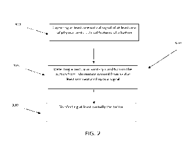
[0055] According to another aspect of the disclosure, as represented in Fig.
2, there is
provided an automated optical method 900 for detecting a sanitary condition on
a
button, for instance on an outer surface thereof. The method according to
- 17 -
CA 03195761 2023-4- 14
WO 2022/077099
PCT/CA2021/051429
embodiments of the present disclosure may be carried out with an automated
optical
detection system 200 as the one described above with reference to Figs. 3 to
7.
[0056] In the embodiment shown, the method 900 comprises a step 910 of
capturing
at least one optical signal of at least one of physical and electrical
features of the
button 400 (for instance an image of a portion 412 of an outer surface 410
thereof); a
step 920 of detecting a particular sanitary condition of the button 400 (for
instance on
the portion of the outer surface thereof) from (or a step 920 of determining
whether the
button has a particular sanitary condition based on) information derived from
the
captured optical signal of the physical and/or electrical feature of the
button; and a
step 930 of disinfecting at least partially the button 400 (for instance the
portion of the
outer surface thereof). In the embodiment shown, the method 900 further
comprises
providing for output an indication of whether at least one of a virus and a
bacterium is
detected onto the portion of the outer surface of the button 400 in real-time.
In the
embodiment shown, the indication of whether the at least one of a virus and a
bacterium is detected is communicated using one or more of the following
interfaces:
a Wi-Fl interface, a Bluetooth interface, a 4G or 5G interface. Different
users (such as
relevant services of a hospital) could receive automated notifications, for
instance via
Web-platforms, text messages and/or dedicated applications and/or software.
Step of detecting the particular sanitary condition
[0057] In the embodiment shown, the step 920 of detecting the particular
sanitary
condition (or step of determining whether the button has the particular
sanitary
condition) is achieved by comparing the captured optical signals with optical
signatures (or reference optical signals) of cell cultures of at least one of
viruses and
bacteria. In the embodiment wherein the button 400 is at least partially made
of a
dielectric material, the cell cultures which are captured to provide the
reference optical
signals are carried out on a dielectric material similar to the dielectric
material of the
button 400.
[0058] In the embodiment shown, the reference optical signatures of cells
cultures are
carried out by at least one of holographic optical system, an interferometric
optical
system, a digital holographic microscopy and a diffraction optical system. For
instance,
the step 920 of detecting the particular sanitary condition comprises using a
machine-
- 18 -
CA 03195761 2023-4- 14
WO 2022/077099
PCT/CA2021/051429
learning algorithm system comprising, for instance, one or more convolutional
neural
networks. In the embodiment shown, the step 920 of detecting the particular
sanitary
condition further comprises training the machine-learning algorithm system to
identify
one or more viruses and/or bacteria.
Step of capturing the optical signal of the button
[0059] In the embodiment shown, the step 910 of capturing optical signals of
the button
400 comprises using at least one of a holographic optical system, an
interferometric
optical system and a diffraction optical system.
Step of disinfecting the button
[0060] In the embodiment shown, the step 930 of disinfecting at least
partially the
portion of the outer surface of the button 400 is carried out after the step
910 of
capturing the optical signals of the button. By doing so, a detection of the
pathogens
on the outer surface 410 of the button 400 is not compromised by the
disinfecting
thereof.
[0061] It could also be conceived a method wherein optical signals of the
outer surface
of the button would be captured while the outer surface is disinfected, in
order to
capture optical signals of pathogens in different states (for instance while
the
pathogens are alive, being killed, killed and the like), and thus more easily
distinguish
patterns from picture noise. An accelerated observation of the different
states of the
pathogens may form an evolution pattern for specific pathogens (i.e.
transformational
patterns). A plurality of optical devices may thus be used and placed in
specific
locations of the system to allow capturing optical signals of the pathogens in
different
states. The present invention will also allow distinguishing noise generated
by dust,
grease, organic material on the user finger and the like and/or acceptable
bacteria
from dangerous ones.
[0062] In the embodiment shown, the step 930 of disinfecting the button 400 is
carried
out via ultra-violet. It could also be conceived a method wherein, when a
unidentified
virus and/or bacterium is detected onto the button (i.e. when a pathogen which
does
not correspond to previously identified pathogens is detected), the step of
disinfecting
the button is postponed in order to maintain the corresponding portion of the
button
- 19 -
CA 03195761 2023-4- 14
WO 2022/077099
PCT/CA2021/051429
unexposed (i.e. within the button-receiving cavity) until an alerted user (for
instance
alerted via a text message, an email or any other communication sent by the
communication module) comes and collects the corresponding sample for further
analysis thereof. It could also be conceived a method wherein, when a non-
identified
virus and/or bacterium is detected onto the button, additional optical signals
are
captured by the optical assembly (for instance optical signals of other
portions of the
button). For instance, information corresponding to this non-identified
pathogen could
be stored and used to improve the sanitary condition detection assembly (for
instance
to further train the machine-learning algorithm thereof). In other words, the
method
could be configured to be self-improved.
Step of rotating the button in the button-receiving cavity
[0063] In the embodiment shown, the button is mounted to a button housing 300
defining a button-receiving cavity 310, and the method 900 also comprises a
step of
rotating the button 400 in the button-receiving cavity. For instance, the
method 900
comprises configuring the button 400 in a first angular configuration in the
button-
receiving cavity 310 wherein the portion of the outer surface 410 of the
button 400 is
at least partially exposed for a user to actuate the button 400 (i.e. to exert
a pressure
thereon); and further comprises configuring the button 400 in a second angular
configuration in the button-receiving cavity 310 wherein the optical signals
of the
button (for instance the images of the portion of the outer surface of the
button) are
captured.
[0064] In the embodiment shown, the method 900 further comprises configuring
the
button 300 in a third angular configuration wherein the portion of the outer
surface is
disinfected.
Additional steps of the method
[0065] In the embodiment wherein the button 400 is an elevator button, the
method
900 may further comprise detecting an actuation of the button 400. It is
appreciated
that the number and the order of the steps of the method can vary from the
embodiment shown. Meta-analyses could also be carried out, in order to compare
different elevators, hospitals, buildings, cities, countries and the like
and/or to compare
- 20 -
CA 03195761 2023-4- 14
WO 2022/077099
PCT/CA2021/051429
outbreaks of bacteria and/or viruses as a function of time, use frequency and
the like.
Such meta-analyses could be used to quantify an efficiency of the system and
an
efficiency of sanitary measures taken by the different places equipped with
the system.
Moreover, traceability of the detected pathogens could further be improved
with an
operatively coupling of the sanitary condition detection assembly with facial
recognition surveillance camera systems and/or with access card and/or smart
phone
identification systems and the like. In the embodiment wherein individuals in
a
building are identified and located via access cards or other biometric
methods, the
detection system can be used to associate the detected pathogen with
individuals. For
example, if a user such as a health care worker uses a RFID card to call an
elevator
or unlock the access to specific levels of a building, any pressing of
elevator buttons
leading to the identification of a specific pathogen could result either in
messaging the
individual to warn of a potential infection or a request to go seek medical
help. The
authorities responsible for health or security as well as the supervisor of a
potentially
infected individual may also receive messages to inform them of the situation,
so they
can take the appropriate actions. Alternatively, the elevator panels could
also contain
a video recording device that substantially continuously saves the video
footage in a
buffer. If a pathogen with potential health consequences is detected, the
content of the
video buffer could be analyzed to automatically identify the individual that
activated
the button or the video segment could be sent to the authorities responsible
for health
and security for the adequate corrective action to be taken. Forecast models
could be
determined on the basis of the collected information to forecast disease
and/or
infection outbreak.
[0066] Several alternative embodiments and examples have been described and
illustrated herein. The embodiments of the invention described above are
intended to
be exemplary only. A person of ordinary skill in the art would appreciate the
features
of the individual embodiments, and the possible combinations and variations of
the
components. A person of ordinary skill in the art would further appreciate
that any of
the embodiments could be provided in any combination with the other
embodiments
disclosed herein. It is understood that the invention may be embodied in other
specific
forms without departing from the central characteristics thereof. The present
examples
and embodiments, therefore, are to be considered in all respects as
illustrative and
-21 -
CA 03195761 2023-4- 14
WO 2022/077099
PCT/CA2021/051429
not restrictive, and the invention is not to be limited to the details given
herein.
Accordingly, while the specific embodiments have been illustrated and
described,
numerous modifications come to mind. The scope of the invention is therefore
intended to be limited by the scope of the appended claims.
- 22 -
CA 03195761 2023-4- 14