Note: Descriptions are shown in the official language in which they were submitted.
WO 2022/098589
PCT/US2021/057501
BLOOD COLLECTION DEVICES, SYSTEMS, AND METHODS
BACKGROUND
[0001] Catheters are commonly used for a variety of infusion
therapies. For example, catheters
may be used for infusing fluids, such as nminal saline solution, various
medicaments, and total
parenteral nutrition, into a patient. Catheters may also be used for
withdrawing blood from the
patient.
[0002] A common type of catheter is an over-the-needle peripheral
intravenous catheter
("PIVC"). As its name implies, the over-the-needle PIVC may be mounted over an
introducer
needle having a sharp distal tip. The PIVC and the introducer needle may be
assembled so that the
distal tip of the introducer needle extends beyond the distal tip of the PIVC
with the bevel of the
needle facing away from skin of the patient. The PIVC and the introducer
needle are typically
inserted at a shallow angle through the skin and into a blood vessel of the
patient, such as an artery,
a vein, or any other vasculature of the patient. Once the PIVC has been
properly placed within the
blood vessel, the introducer needle may be withdrawn and the PIVC may be
secured within the
blood vessel by securing a catheter adapter (coupled with the PIVC) to the
skin of the patient with
dressing. Other common types of catheters include, but are not limited to,
peripherally inserted
central catheters (-PICC") and central venous catheters ("CVC").
[0003] A properly placed catheter may be utilized by a clinician to
withdraw blood from the
patient. Moreover, blood draw procedures are typically only performed with a
newly inserted
catheter in order to avoid certain risks. For example, during a blood draw
procedure the clinician
will typically: (1) insert a new catheter/catheter adapter; (2) couple a blood
draw device to the
catheter adapter; (3) collect a blood sample from the patient with the blood
draw device; (4)
decouple the blood draw device from the catheter adapter; (4) couple a flush
device to the catheter
-1-
CA 03196671 2023- 4- 25
WO 2022/098589
PCT/US2021/057501
adapter; (5) flush the catheter/catheter adapter with the flush device; and
(6) decouple the flush
device from the catheter adapter.
[0004] However, each of these steps introduce complexity and
inefficiencies to the blood draw
procedure (e.g., multiple connection/disconnection steps), limit blood draw
procedures to newly
inserted catheters, and increase certain risks to the patient. Examples of
risks that may be increased
include drug contamination of the blood sample, hemolysis of the blood sample,
increased risk of
infection, increased risk of catheter occlusion, increased risk of catheter
migration, etc.
[0005] The subject matter claimed herein is not limited to
embodiments that solve any
disadvantages or that operate only in environments such as those described
above. Rather, this
background is only provided to illustrate one example technology area where
some
implementations described herein may be practiced.
SUMMARY
[0006] The present disclosure generally relates to blood collection
devices, systems, and
methods. The various blood collection devices, systems, and methods of the
present disclosure
have been developed in response to the present state of the art, and in
particular, in response to the
problems and needs in the art that have not yet been fully solved by currently
available devices,
systems, and methods for collecting blood from a patient.
[0007] In some embodiments, a blood draw system may include at least
one catheter adapter
connector configured to engage a catheter adapter and place the at least one
catheter adapter
connector in fluid communication with the catheter adapter. The blood draw
system may also
include at least one blood draw device which may be in selective fluid
communication with the at
least one catheter adapter connector. The at least one blood draw device may
be configured to
-2-
CA 03196671 2023- 4- 25
WO 2022/098589
PCT/US2021/057501
draw blood from a blood vessel of a patient. A first valve may be configured
to selectively permit
fluid communication between the at least one blood draw device and the at
least one catheter
adapter connector. A flush device may be in selective fluid communication with
the at least one
catheter adapter connector and the flush device may be configured to flush the
catheter adapter
with fluid ejected from the flush device. A second valve may be configured to
selectively permit
fluid communication between the flush device and the at least one catheter
adapter connector.
[0008] In some embodiments, the at least one catheter adapter
connector may include at least
one of a needle, a wing needle set, a needleless connector, a luer lock
connector, a lure slip
connector, a luer taper connector, an extension set, and an extension tube.
[0009] In some embodiments, the at least one blood draw device may
include at least one of a
syringe and a vacutainer.
[0010] In some embodiments, the first valve and the second valve may
include at least one of
a stopcock valve, a two-way stopcock valve, a three-way stopcock valve, a
check valve, a slide
clamp, and a pinch clamp.
[0011] In some embodiments, the flush device may include a syringe
filled with a saline
solution.
[0012] In some embodiments, the blood draw system may further include
at least one fluid
conduit coupled to the at least one catheter adapter connector. The at least
one fluid conduit may
be configured to place at least one of the flush device and the at least one
blood draw device in
fluid communication with the at least one catheter adapter connector.
[0013] In some embodiments, the at least one catheter adapter
connector may include a needle
that is at least partially housed within a protective needle housing.
-3-
CA 03196671 2023- 4- 25
WO 2022/098589
PCT/US2021/057501
[00141 In some embodiments, a protective needle housing system may
include a needle and a
protective needle housing. The protective needle housing may include a needle
passageway
configured to receive at least a portion of the needle therein and a needle
block configured to move
between a closed position and an open position. In the closed position, the
needle block may
prevent the needle from advancing distally through the needle passageway. In
the open position,
an aperture formed in the needle block may be placed in alignment with the
needle passageway to
allow the needle to advance distally through the needle passageway.
[0015] In some embodiments, the protective needle housing system may
also include a resilient
member configured to bias the needle block in the closed position.
[00161 In some embodiments, the resilient member include at least one
of a spring clip and a
helical spring.
[0017] In some embodiments, the needle block may include a first
engagement surface
configured to engage with a second engagement surface of a catheter adapter,
such that, as the
second engagement surface of the catheter adapter engages the first engagement
surface of the
needle block, the needle block is moved from the closed position to the open
position.
[0018] In some embodiments, the protective needle housing may include
an engagement
feature configured to couple the protective needle housing to a catheter
adapter.
[0019] In some embodiments, a distal end of the needle may include a
closed tip and an
aspiration aperture formed in a sidewall of the needle proximate the closed
tip.
[0020] In some embodiments, the needle may include a bumper
configured to prevent the
needle from moving proximally out of the protective needle housing.
[0021] In some embodiments, a method of drawing blood from a patient via a
blood draw
system may include coupling at least one catheter adapter connector to a
catheter adapter in order
-4-
CA 03196671 2023- 4- 25
WO 2022/098589
PCT/US2021/057501
to place the at least one catheter adapter connector in fluid communication
with the catheter
adapter. The method may also include adjusting a first valve to permit fluid
communication
between at least one blood draw device and the at least one catheter adapter
connector. The at least
one blood draw device may be configured to draw blood from a blood vessel of a
patient. The
method may also include aspirating blood into the at least one blood draw
device through the at
least one catheter adapter connector. The method may also include adjusting
the first valve to
prevent fluid communication between the at least one blood draw device and the
at least one
catheter adapter connector. The method may further include adjusting a second
valve to permit
fluid communication between a flush device and the at least one catheter
adapter connector. The
method may additionally include flushing the catheter adapter with fluid
ejected from the flush
device.
[0022] In some embodiments, the method may also include adjusting the
second valve to
prevent fluid communication between the flush device and the at least one
catheter adapter
connector and to permit fluid communication between a second blood draw device
and the at least
one catheter adapter connector. The method may also include aspirating blood
into the second
blood draw device through the at least one catheter adapter connector.
[0023] In some embodiments, the at least one catheter adapter
connector may include a first
catheter adapter connector and a second catheter adapter connector.
[0024] In some embodiments, the at least one catheter adapter
connector may include at least
one of a needle, a wing needle set, a needleless connector, a luer lock
connector, a lure slip
connector, a luer taper connector, an extension set, and an extension tube.
[0025] In some embodiments, the at least one catheter adapter
connector may include a needle
that is at least partially housed within a protective needle housing.
-5-
CA 03196671 2023- 4- 25
WO 2022/098589
PCT/US2021/057501
[0026] In some embodiments, the first valve and the second valve may
include at least one of
a stopcock valve, a two-way stopcock valve, a three-way stopcock valve, a
check valve, a slide
clamp, and a pinch clamp.
[0027] It is to be understood that both the foregoing general
description and the following
detailed description are examples and explanatory and are not restrictive of
the embodiments of
the present disclosure, as claimed. It should be understood that the various
embodiments of the
present disclosure are not limited to the arrangements and instrumentality
shown in the drawings.
It should also be understood that the embodiments of the present disclosure
may be combined, or
that other embodiments may be utilized and that structural changes, unless so
claimed, may be
made without departing from the scope of the various embodiments of the
present disclosure. The
following detailed description is, therefore, not to be taken in a limiting
sense.
BRIEF DESCRIPTION OF THE DRAWINGS
[0028] Example embodiments will be described and explained with
additional specificity and
detail through the use of the accompanying drawings in which:
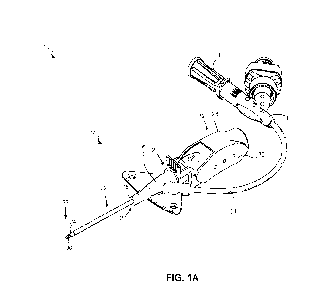
[0029] FIG. lA is a perspective top view of an example catheter
system, according to some
embodiments;
[0030] FIG. 1B is a cross-sectional top view of the catheter system
of FIG. 1A, according to
some embodiments;
[0031] FIG. 2A is a perspective view of a protective needle housing,
according to some
embodiments;
[0032] FIG. 2B is a front view of the protective needle housing of
FIG. 2A in a closed position,
according to some embodiments;
-6-
CA 03196671 2023- 4- 25
WO 2022/098589
PCT/US2021/057501
[0033] FIG. 2C is a front view of the protective needle housing of
FIG. 2A in an open position,
according to some embodiments;
[0034] FIG. 2D is a cross-sectional side view of the protective
needle housing of FIG. 2A in a
closed position, according to some embodiments;
[0035] FIG. 2E is a cross-sectional side view of the protective
needle housing of FIG. 2A in an
open position, according to some embodiments;
[0036] FIG. 3A is a side view of a needle, according to some
embodiments;
[0037] FIG. 3B is a close up view of a distal end of the needle of
FIG. 3A, according to some
embodiments;
[0038] FIG. 3C is a close up view of an intermediate portion of the
needle of FIG. 3A, according
to some embodiments;
[0039] FIG. 4A is a cross-sectional side view of a protective needle
housing system in a closed
position, according to some embodiments;
[0040] FIG. 4B is a cross-sectional side view of the protective
needle housing system of FIG.
4A in an open position, according to some embodiments;
[0041] FIG. 5 is a cross-sectional side view of an example catheter
adapter, according to some
embodiments;
[0042] FIG. 6 is a cross-sectional side view of the catheter adapter
of FIG. 5 coupling to the
protective needle housing system of FIG. 4A in a closed position, according to
some embodiments;
[0043] FIG. 7 is a cross-sectional side view of the catheter adapter
of FIG. 5 coupled to the
protective needle housing system of FIG. 4A in an open position, according to
some embodiments;
-7-
CA 03196671 2023- 4- 25
WO 2022/098589
PCT/US2021/057501
[0044] FIG. 8 is a cross-sectional side view of the catheter adapter
of FIG. 5 coupled to the
protective needle housing system of FIG. 4A in an open position with the
needle moved distally
within the catheter adapter, according to some embodiments;
[0045] FIG. 9A is a front view of a protective needle housing in a
closed position, according to
an alternative embodiment;
[0046] FIG. 9B is a front view of the protective needle housing of
FIG. 9A in an open position,
according to an alternative embodiment;
[0047] FIG. 10 is a side view of a blood collection set, according to
some embodiments;
[0048] FIG. 11 is a side view of an alternative blood collection set,
according to some
embodiments;
[0049] FIG. 12 is a side view of an alternative blood collection set,
according to some
embodiments;
[0050] FIG. 13 is a side view of an alternative blood collection set,
according to some
embodiments;
[0051] FIG. 14 is a side view of an alternative blood collection set,
according to some
embodiments;
[0052] FIG. 15 is a side view of an alternative blood collection set,
according to some
embodiments;
[0053] FIG. 16 is a side view of an alternative blood collection set,
according to some
embodiments; and
[0054] FIG. 17 is a flowchart of a method for drawing blood from a
patient via a blood draw
system, according to some embodiments.
-8-
CA 03196671 2023- 4- 25
WO 2022/098589
PCT/US2021/057501
[00551 It is to be understood that the Figures are for purposes of
illustrating the concepts of the
present disclosure and may not be drawn to scale. Furthermore, the Figures
illustrate example
embodiments and do not represent limitations to the scope of the present
disclosure.
DESCRIPTION OF EMBODIMENTS
[0056] Example embodiments of the present disclosure may be best
understood by reference to
the Figures, wherein like parts are designated by like numerals throughout. It
will be readily
understood that the components of the present disclosure, as generally
described and illustrated in
the Figures herein, could be arranged and designed in a wide variety of
different configurations.
Thus, the following more detailed description of the embodiments of the
apparatus and systems,
as represented in the Figures, is not intended to limit the scope of the
present disclosure, as claimed
in this or any other application claiming priority to this application, but is
merely representative of
example embodiments of the present disclosure.
[0057] Referring to FIGS. lA and 1B, in some embodiments, a catheter
system 10 may include
a needle assembly 12 and a catheter assembly 14, according to some
embodiments. FIGS. lA and
1B illustrate the catheter system 10 in an insertion position, ready for
insertion into a vein of a
patient (not shown). In some embodiments, the catheter assembly 14 may include
a catheter
adapter or catheter adapter body 16, which may include a proximal end 20, a
distal end 18, and a
catheter adapter channel 21 formed within the catheter adapter body 16 and
extending between the
proximal and distal ends 20, 18 of the catheter adapter body 16. In some
embodiments, the catheter
adapter body 16 may include a septum 70 coupled to the catheter adapter body
16 adjacent the
catheter adapter channel 21. In some embodiments, the septum 70 may be a
single component
septum. In some embodiments, the septum 70 may be a multi-component septum. In
some
-9-
CA 03196671 2023- 4- 25
WO 2022/098589
PCT/US2021/057501
embodiments, the catheter assembly 14 may include a catheter 22, which may
include a proximal
end 26, a distal end 24, and a catheter lumen 27 extending between the
proximal and distal ends
26, 24 of the catheter 22. In some embodiments, the catheter 22 may include a
peripheral
intravenous catheter ("PIVC"). In some embodiments, the proximal end 26 of the
catheter 22 may
be secured within the catheter adapter body 16.
[0058] In some embodiments, the needle assembly 12 may include a needle hub
28, which may
be removably coupled to the catheter adapter body 16. In some embodiments, the
needle assembly
12 may include an introducer needle 30. In some embodiments, a proximal end 31
of the introducer
needle 30 may be secured within the needle hub 28. In some embodiments, the
introducer needle
30 may extend through the catheter lumen 27 and a distal end 33 of the
introducer needle 30 may
protrude from the distal end 24 of the catheter 22 when the catheter system 10
is in an insertion
position and ready for insertion into a vein of a patient.
[0059] In some embodiments, the needle assembly 12 may include a
needle grip 32, which a
clinician may grip and move proximally to withdraw the introducer needle 30
from the vein once
placement of the catheter 22 within the vein is confirned. In some
embodiments, the catheter
system 10 may include an extension tube 34. In some embodiments, a distal end
of the extension
tube 34 may be coupled to the catheter adapter body 16 and a proximal end of
the extension tube
34 may be coupled to an adapter 36. In some embodiments, the catheter adapter
body 16 may
include an access port 80, which may be in fluid communication with the
catheter adapter channel
21. In some embodiments, a distal end of the extension tube 34 may be coupled
to the access port
80, such that the extension tube 34 may be in fluid communication with the
catheter adapter
channel 21 via the access port 80.
-10-
CA 03196671 2023- 4- 25
WO 2022/098589
PCT/US2021/057501
[0060] In some embodiments, a fluid infusion device (not shown) may
be coupled to the adapter
36 to deliver fluid to the patient via the catheter 22 inserted in the vein,
once the introducer needle
30 is removed from the catheter system 10. In some embodiments, a blood
collection device may
be coupled to the adapter 36 to withdraw blood from the patient via the
catheter 22 inserted within
the vein.
[0061] The catheter system 10 may include straight, ported,
integrated, and conventional
catheters. For example, in some embodiments, the catheter system 10 may be
integrated, having
the extension tube 34 integrated within the catheter adapter body 16, such as,
for example, the BD
NEXIVA 'I" Closed IV Catheter System, the BD NEXIVA' m DIFFUSICS m Closed IV
Catheter
System, the BD PEGASUSTM Safety Closed IV Catheter System, or another
integrated catheter
system. In some embodiments, the catheter system 10 may be non-integrated,
without the
extension tube 34.
[0062] In some embodiments, the catheter system 10 may be vented to
observe blood and
facilitate proximal flow of blood within the introducer needle 30 and/or the
catheter 22. In some
embodiments, the catheter system 10 may be vented in any suitable manner. For
example, a vent
plug 38 may be coupled to the adapter 36 during insertion of the catheter 22
into the patient. In
some embodiments, the vent plug 38 may be permeable to air but not to blood.
In some
embodiments, the catheter 22, the catheter adapter body 16, the extension tube
34, the adapter 36,
and the vent plug 38 may be in fluid communication. As another example, in
some embodiments,
the needle hub 28 may include a flash chamber.
[0063] FIGS. 2A-2E illustrate various views of a protective needle
housing 200, according to
some embodiments. Specifically, FIG. 2A is a perspective view of the
protective needle housing
200; FIG. 2B is a front view of the protective needle housing 200 in a closed
position; FIG. 2C is
-11 -
CA 03196671 2023- 4- 25
WO 2022/098589
PCT/US2021/057501
a front view of the protective needle housing 200 in an open position; FIG. 2D
is a cross-sectional
side view of the protective needle housing 200 in a closed position; and FIG.
2E is a cross-sectional
side view of the protective needle housing 200 in an open position.
[0064] In general, the protective needle housing 200 may include a
proximal end 201, a distal
end 202, an engagement feature 210 located at the distal end 202 of the
protective needle housing
200, an engagement slot 212, a needle passageway 240 extending between the
proximal and distal
ends 201, 202 of the protective needle housing 200, a reduced inner diameter
portion 242 of the
needle passageway 240 located at the proximal end 201 of the protective needle
housing 200, and
a needle block 220 including one or more of: an aperture 230, a first
engagement surface 261, and
a resilient member 250. Operation of the protective needle housing 200 will be
discussed in more
detail below with respect to FIGS. 4A-8.
[0065] FIGS. 3A-3C illustrate various views of a needle 300,
according to some embodiments.
Specifically, FIG. 3A is a side view of the needle 300; FIG. 311 is a close up
top view of a distal
end of the needle 300; and FIG. 3C is a close up view of an intermediate
portion of the needle 300.
[0066] In general, the needle 300 may include a needle cannula 305
extending between a
proximal end 301 and a distal end 302 of the needle 300, a hub 340 coupled to
the proximal end
301 of the needle 300, a closed tip 310 located at the distal end 302 of the
needle 300, an aspiration
aperture 320 formed in a sidewall of the needle cannula 305 located proximate
the closed tip 310,
and a bumper 330 coupled to the needle cannula 305. The operation of the
needle 300 and the
protective needle housing 200 will now be discussed with reference to FIGS. 4A-
8.
[0067] FIGS. 4A and 4B illustrate various views of a protective
needle housing system 400,
according to some embodiments. Specifically, FIG. 4A is a cross-sectional side
view of the
protective needle housing system 400 in a closed position, and FIG. 4B is a
cross-sectional side
-12-
CA 03196671 2023- 4- 25
WO 2022/098589
PCT/US2021/057501
view of the protective needle housing system 400 in an open position. In
general, the protective
needle housing system 400 may include the needle 300 of FIGS. 3A-3C slidably
coupled within
the protective needle housing 200 of FIGS. 2A-2E.
[0068] The needle 300 may be held captive within the protective
needle housing 200 in the
proximal direction via the bumper 330 that protrudes from the needle cannula
305. The bumper
330 may have a larger outer diameter than the reduced inner diameter portion
242 of the needle
passageway 240. Thus, the bumper 330 may be configured to prevent the needle
300 from moving
too far in the proximal direction to retain the needle 300 within the
protective needle housing 200
when a clinician pulls the needle 300 in the proximal direction. The needle
300 may also be held
captive within the protective needle housing 200 in the distal direction via
the needle block 220
when the needle block 220 is in the closed position (see FIG. 4A), or via the
hub 340 when the
needle block 220 is in the open position (see FIG. 4B). Thus, the needle block
220 and/or the hub
340 may prevent the needle 300 from moving too far in the distal direction to
retain the needle 300
within the protective needle housing 200 when a clinician pushes the needle
300 in the distal
direction. In this manner, the needle passageway 240 and/or the reduced inner
diameter portion
242 of the needle passageway 240 may each be configured to receive at least a
portion of the needle
300, and capturing the closed tip 310 of the needle 300 within the protective
needle housing 200
provides an increased level of safety to the clinician against accidental
needle punctures. The
closed tip 310 may also reduce blood hemolysis and reduce tears and
contamination caused by the
closed tip 310 puncturing through a septum.
[0069] As previously noted, the needle block 220 may be configured to
move between a closed
position (e.g., see FIGS. 2A, 2B, 2D, and 4A) and an open position (e.g. see
FIGS. 2C, 2E, and
4B). In the closed position, the needle block 220 may prevent the needle 300
from advancing
-13-
CA 03196671 2023- 4- 25
WO 2022/098589
PCT/US2021/057501
distally through the needle passageway 240 by blocking the closed tip 310 of
the needle 300 and
preventing distal translation of the needle 300 through the needle passageway
240, as shown in
FIG. 4A. In the open position, the aperture 230 formed in the needle block 220
may be placed in
alignment with the needle passageway 240 to allow the needle 300 to advance
distally through the
needle passageway 240, as shown in FIG. 4B.
[0070] The resilient member 250 may be configured to apply a biasing
force on the needle
block 220 in order to preferentially bias the resilient member 250 in the
closed position. In the
embodiment shown if FIGS. 2A-2E, 4A, 4B, and 6-8, the resilient member 250 may
include a
spring clip configured to bias the needle block 220 in the upward/closed
position. However, it will
be understood that other biasing structures are contemplated herein (e.g., see
FIGS. 9A and 9B).
[0071] FIG. 5 illustrates a cross-sectional side view of a catheter
adapter 500, according to
some embodiments. In general, the catheter adapter 500 may include a catheter
adapter body 516
and a catheter 522. The catheter adapter body 516 may include a proximal end
520, a distal end
518, an inferior surface 540, a superior surface 542, and a catheter adapter
channel 521 formed
within the catheter adapter body 516 and extending between the proximal and
distal ends 520, 518
of the catheter adapter body 516. In some embodiments, the catheter adapter
body 516 may include
a first septum 571 and a second septum 572. The first septum 571 may be
located toward the
proximal end 520 of the catheter adapter body 516 and the second septum 572
may be coupled
within the catheter adapter body 516 adjacent the catheter adapter channel
521. A septum channel
575 may be formed intermediate the first septum 571 and the second septum 572.
In some
embodiments, the septum 570 may be a multi-component septum. In some
embodiments (not
shown) the catheter adapter 500 septum may utilize a single component septum.
In some
-14-
CA 03196671 2023- 4- 25
WO 2022/098589
PCT/US2021/057501
embodiments, the catheter adapter body 516 may also include an access port
(not shown in FIG.
5) that may be in fluid communication with the catheter adapter channel 521.
[0072] The catheter 522 may include a proximal end 526, a distal end
524, and a catheter lumen
527 extending between the proximal and distal ends 526, 524 of the catheter
522. In some
embodiments, the catheter 522 may include a peripheral intravenous catheter
("PIVC"). In some
embodiments, the proximal end 526 of the catheter 522 may be coupled to and/or
secured within
the catheter adapter body 516, such that the catheter lumen 527 may be in
fluid communication
with the catheter adapter channel 521.
[0073] FIGS. 6-8 illustrate various views of the catheter adapter 500
of FIG. 5 coupling to the
protective needle housing system 400 of FIG. 4A, according to some
embodiments. Specifically,
FIG. 6 is a cross-sectional side view of the catheter adapter 500 coupling to
the protective needle
housing system 400 in a closed position; FIG. 7 is a cross-sectional side view
of the catheter
adapter 500 fully coupled to the protective needle housing system 400 in an
open position; and
FIG. 8 is a cross-sectional side view of the catheter adapter 500 coupled to
the protective needle
housing system 400 in an open position with the needle 300 moved distally and
projecting inside
of the catheter adapter 500.
[0074] FIG. 6 illustrates the proximal end 520 of the catheter
adapter 500 as it is slidably
received within the engagement feature 210 of the protective needle housing
200. As the proximal
end 520 of the catheter adapter 500 is received within the engagement feature
210 of the protective
needle housing 200, the first engagement surface 261 of the needle block 220
will engage a second
engagement surface 262 formed on the proximal end 520 of the catheter adapter
500. The first
engagement surface 261 of the needle block 220 and the second engagement
surface 262 of the
catheter adapter 500 may each be angled toward the proximal direction. In this
manner, the first
-15-
CA 03196671 2023- 4- 25
WO 2022/098589
PCT/US2021/057501
engagement surface 261 may be configured to engage the second engagement
surface 262 of the
catheter adapter 500, such that, as the second engagement surface 262 of the
catheter adapter 500
engages the first engagement surface 261 of the needle block 220, the needle
block 220 moves
from the closed position to the open position. Thus, when a clinician fully
couples the protective
needle housing 200 to the catheter adapter 500 by moving the catheter adapter
500 in the direction
of arrow 700, the needle block 220 may automatically move from the closed
position to the open
position, as shown in FIG. 7. Once the needle block 220 is moved to the open
position, the clinician
is free to move the needle 300 distally to insert the needle 300 into the
catheter adapter 500, as
shown in FIG. 8.
[0075] FIGS. 9A and 9B illustrate two views of a protective needle
housing 900, according to
an alternative embodiment. Specifically. FIG. 9A is a front view of the
protective needle housing
900 in a closed position and FIG. 9B is a front view of the protective needle
housing 900 in an
open position. In general, the protective needle housing 900 may include
similar features and
structures to the protective needle housing 200 shown in FIGS. 2A-2E, such as
an engagement
feature 910, a needle block 920 and an aperture 930. However, the protective
needle housing 900
may utilize an alternative structure including a resilient member 950 (e.g., a
helical spring) and
needle block arm 970, which may be configured to toggle the needle block 920
between the open
and closed positions. The needle block 920 may also be configured to
automatically move to the
open position upon coupling with the catheter adapter 500.
[0076] However, it will be understood that any number of different
resilient member structures
or configurations are envisioned herein which may be utilized to toggle a
needle block between
the open and closed positions and/or to apply a biasing force to the needle
block toward the closed
position. It will also be understood that any of the catheter adapter
structures described herein
-16-
CA 03196671 2023- 4- 25
WO 2022/098589
PCT/US2021/057501
and/or any of the protective needle housing structures or systems disclosed
herein may be utilized
with any of the blood draw collection sets/systems described below.
[0077] FIGS. 10-16 illustrate various example blood draw collection
sets, according to some
embodiments. Specifically, FIG. 10 is a side view of an example blood
collection set 1000; FIG.
11 is a side view of an example blood collection set 1100; FIG. 12 is a side
view of an example
blood collection set 1200; FIG. 13 is a side view of an example blood
collection set 1300; FIG. 14
is a side view of an example blood collection set 1400; FIG. 15 is a side view
of an example blood
collection set 1500; and FIG. 16 is a side view of an example blood collection
set 1600.
[0078] The example blood collection set 1000 shown in FIG. 10 may
generally include a first
catheter adapter connector 1010, a first fluid conduit 1051, a second fluid
conduit 1052, a third
fluid conduit 1053, a first connector 1061, a first valve 1031, a second valve
1032, a first blood
draw device 1021, and a flush device 1040.
[0079] The first catheter adapter connector 1010 may he configured to
engage with a catheter
adapter (not shown) in order to place the first catheter adapter connector
1010 in fluid
communication with the catheter adapter. The catheter adapter may also include
a catheter, which
may be placed within a blood vessel of a patient (not shown). The first
catheter adapter connector
1010, as well as any other catheter adapter connector disclosed herein, may
include at least one of
a needle, a wing needle set, a needleless connector (e.g., a Q-SYTETm
connector, a MAX ZERO TM
connector, a SMARTSITETm connector, etc.), a luer lock connector, a lure slip
connector, a luer
taper connector, an extension set, and/or an extension tube.
[0080] The first blood draw device 1021 may be placed in selective
fluid communication with
the first catheter adapter connector 1010 via the first fluid conduit 1051 and
the second fluid
conduit 1052, which may be coupled together via the first connector 1061. The
first blood draw
-17-
CA 03196671 2023- 4- 25
WO 2022/098589
PCT/US2021/057501
device 1021, as well as any other blood draw device disclosed herein, may be
configured to draw
blood from the blood vessel of the patient and may include at least one of a
syringe and a
VACUTAINERTM.
[00811 The first valve 1031 may be configured to selectively permit
fluid communication
between the first blood draw device 1021 and the first catheter adapter
connector 1010. The first
valve 1031, as well as any other valve disclosed herein, may include at least
one of a stopcock
valve, a two-way stopcock valve, a three-way stopcock valve, a check valve, a
slide clamp, and a
pinch clamp. Once the first valve 1031 has been moved to an open position, the
clinician may draw
blood into the first blood draw device 1021. The first valve 1031 may then be
moved to a closed
position for subsequent steps during a blood draw procedure, as desired.
[0082] The flush device 1040 may be configured to flush the catheter
adapter with fluid ejected
from the flush device 1040 after blood has been drawn from the patient. In
some embodiments,
the flush device 1040 may include a syringe filled with a saline solution,
such as a PosiFlush 1m.
The flush device 1040 may be placed in selective fluid communication with the
first catheter
adapter connector 1010 via the first fluid conduit 1051 and the third fluid
conduit 1053, which may
be coupled together via the first connector 1061.
[0083] The second valve 1032 may be configured to selectively permit
fluid communication
between the flush device 1040 and the first catheter adapter connector 1010.
Once the second valve
1032 has been moved to an open position, the clinician may flush the catheter
adapter with fluid
ejected from the flush device 1040. The second valve 1032 may then be moved to
a closed position
for subsequent steps during a blood draw procedure, as desired.
[0084] The example blood collection set 1100 shown in FIG. 11 may
generally include a first
catheter adapter connector 1110, a first fluid conduit 1151, a second fluid
conduit 1152, a third
-18-
CA 03196671 2023- 4- 25
WO 2022/098589
PCT/US2021/057501
fluid conduit 1153, a fourth fluid conduit 1154, a fifth fluid conduit 1155, a
first connector 1161,
a second connector 1162, a first valve 1131, a second valve 1132, a third
valve 1133, a fourth valve
1134, a first blood draw device 1121, a second blood draw device 1122, and a
flush device 1140.
[0085] The first catheter adapter connector 1110 may be configured to
engage with a catheter
adapter 1170 in order to place the first catheter adapter connector 1110 in
fluid communication
with the catheter adapter 1170. The catheter adapter 1170 may also include a
catheter 1171, which
may be placed within a blood vessel of a patient (not shown).
[0086] The first blood draw device 1121 may be placed in selective
fluid communication with
the first catheter adapter connector 1110 via the first fluid conduit 1151 and
the second fluid
conduit 1152, which may be fluidly coupled via the first connector 1161.
[0087] The first valve 1131 and/or the fourth valve 1134 may be
configured to selectively
permit fluid communication between the first blood draw device 1121 and the
first catheter adapter
connector 1110. Once the first valve 1131 and/or the fourth valve 1134 have
been moved to open
positions, the clinician may draw blood into the first blood draw device 1121.
The first valve 1131
and/or the fourth valve 1134 may then be moved to closed positions for
subsequent steps during a
blood draw procedure, as desired.
[0088] The second blood draw device 1122 may be placed in selective
fluid communication
with the first catheter adapter connector 1110 via the first fluid conduit
1151, the fourth fluid
conduit 1154 and the fifth fluid conduit 1155, which may be fluidly coupled
via the first connector
1161 and/or the second connector 1162.
[0089] The first valve 1131, the third valve 1133, and/or the fourth
valve 1134 may each be
configured to selectively permit fluid communication between the second blood
draw device 1122
and the first catheter adapter connector 1110. Once the first valve 1131. the
third valve 1133,
-19-
CA 03196671 2023- 4- 25
WO 2022/098589
PCT/US2021/057501
and/or the fourth valve 1134 have each been moved to open positions, the
clinician may draw
blood into the second blood draw device 1122. The first valve 1131, the third
valve 1133, and/or
the fourth valve 1134 may then be moved to closed positions for subsequent
steps during a blood
draw procedure, as desired. In some embodiments, blood may be drawn into the
second blood
draw device 1122 in order to remove blood from the patient's vein containing
one or more drugs
(e.g., from a prior infusion) before a clean blood sample may then be drawn
into the first blood
draw device 1121.
[0090] The flush device 1140 may be configured to flush the catheter
adapter 1170 with fluid
ejected from the flush device 1140 after blood has been drawn from the
patient. The flush device
1140 may be placed in selective fluid communication with the first catheter
adapter connector
1110 via the first fluid conduit 1151, the third fluid conduit 1153, and the
fifth fluid conduit 1155,
which may be fluidly coupled via the first connector 1161 and/or the second
connector 1162.
[0091] The first valve 1131, the second valve 1132, and/or the fourth
valve 1134 may each be
configured to selectively permit fluid communication between the flush device
1140 and the first
catheter adapter connector 1110. Once the first valve 1131, the second valve
1132, and/or the
fourth valve 1134 have been moved to open positions, the clinician may flush
the catheter adapter
1170 with fluid ejected from the flush device 1140. The first valve 1131, the
second valve 1132,
and/or the fourth valve 1134 may then be moved to closed positions for
subsequent steps during a
blood draw procedure, as desired.
[0092] The example blood collection set 1200 shown in FIG. 12 may
generally include a first
catheter adapter connector 1210, a first fluid conduit 1251, a second fluid
conduit 1252, a third
fluid conduit 1253, a fourth fluid conduit 1254, a fifth fluid conduit 1255, a
first connector 1261,
-20-
CA 03196671 2023- 4- 25
WO 2022/098589
PCT/US2021/057501
a first valve 1231, a second valve 1232, a third valve 1233, a first blood
draw device 1221, a second
blood draw device 1222, and a flush device 1240.
[0093] The first catheter adapter connector 1210 may be configured to
engage with a catheter
adapter 1270 in order to place the first catheter adapter connector 1210 in
fluid communication
with the catheter adapter 1270. The catheter adapter 1270 may also include a
catheter 1271, which
may be placed within a blood vessel of a patient (not shown).
[0094] The first blood draw device 1221 may be placed in selective
fluid communication with
the first catheter adapter connector 1210 via the first fluid conduit 1251 and
the second fluid
conduit 1252, which may be fluidly coupled via the first connector 1261.
[00951 The first valve 1231 and/or the third valve 1233 may be
configured to selectively permit
fluid communication between the first blood draw device 1221 and the first
catheter adapter
connector 1210. Once the first valve 1231 and/or third valve 1233 have been
moved to open
positions, the clinician may draw blood into the first blood draw device 1221.
The first valve 1231
and/or third valve 1233 may then be moved to closed positions for subsequent
steps during a blood
draw procedure, as desired.
[0096] The second blood draw device 1222 may be placed in selective
fluid communication
with the first catheter adapter connector 1210 via the first fluid conduit
1251, the fourth fluid
conduit 1254 and the fifth fluid conduit 1255, which may be fluidly coupled
via the first connector
1261.
[0097] The first valve 1231, the second valve 1232, and/or the third
valve 1233 may each be
configured to selectively permit fluid communication between the second blood
draw device 1222
and the first catheter adapter connector 1210. Once the first valve 1231, the
second valve 1232,
and/or the third valve 1233 have each been moved to open positions for the
second blood draw
-21-
CA 03196671 2023- 4- 25
WO 2022/098589
PCT/US2021/057501
device 1222, the clinician may draw blood into the second blood draw device
1222. The first valve
1231, the second valve 1232, and/or the third valve 1233 may then be moved to
closed positions
for the second blood draw device 1222 during subsequent steps of a blood draw
procedure, as
desired. In some embodiments, blood may be drawn into the second blood draw
device 1222 in
order to remove blood from the patient's vein containing one or more drugs
(e.g., from a prior
infusion) before a clean blood sample may then be drawn into the first blood
draw device 1221.
[0098] The flush device 1240 may be configured to flush the catheter
adapter 1270 with fluid
ejected from the flush device 1240 after blood has been drawn from the
patient. The flush device
1240 may be placed in selective fluid communication with the first catheter
adapter connector
1210 via the first fluid conduit 1251, the third fluid conduit 1253, and the
fifth fluid conduit 1255,
which may be fluidly coupled via the first connector 1261.
[0099] The first valve 1231, the second valve 1232, and/or the third
valve 1233 may each be
configured to selectively permit fluid communication between the flush device
1240 and the first
catheter adapter connector 1210. Once the first valve 1231, the second valve
1232, and/or the third
valve 1233 have each been moved to open positions for the flush device 1240,
the clinician may
flush the catheter adapter 1270 with fluid ejected from the flush device 1240.
The first valve 1231,
the second valve 1232, and/or third valve 1233 may then be moved to closed
positions for the flush
device 1240 during subsequent steps of a blood draw procedure, as desired.
[00100] The example blood collection set 1300 shown in FIG. 13 may generally
include a first
catheter adapter connector 1310, a second catheter adapter connector 1312, a
first fluid conduit
1351, a second fluid conduit 1352, a third fluid conduit 1353, a fourth fluid
conduit 1354, a fifth
fluid conduit 1355, a sixth fluid conduit 1356, a first connector 1361, a
second connector 1362, a
-22-
CA 03196671 2023- 4- 25
WO 2022/098589
PCT/US2021/057501
third connector 1363, a first valve 1331, a second valve 1332, a third valve
1333, a fourth valve
1334, a first blood draw device 1321, a second blood draw device 1322, and a
flush device 1340.
[00101] The first catheter adapter connector 1310 may be configured to engage
with a catheter
adapter 1370 in order to place the first catheter adapter connector 1310 in
fluid communication
with the catheter adapter 1370. The catheter adapter 1370 may also include a
catheter 1371, which
may be placed within a blood vessel of a patient (not shown).
[00102] The first blood draw device 1321 may be placed in selective fluid
communication with
the first catheter adapter connector 1310 via the first fluid conduit 1351 and
the second fluid
conduit 1352, which may be fluidly coupled via the first connector 1361.
[00103] The first valve 1331 may be configured to selectively permit fluid
communication
between the first blood draw device 1321 and the first catheter adapter
connector 1310. Once the
first valve 1331 has been moved to an open position, the clinician may draw
blood into the first
blood draw device 1321. The first valve 1331 may then be moved to a closed
position for
subsequent steps during a blood draw procedure, as desired.
[00104] The second blood draw device 1322 may be placed in selective fluid
communication
with the first catheter adapter connector 1310 via the first fluid conduit
1351, the fourth fluid
conduit 1354, and the fifth fluid conduit 1355, which may be fluidly coupled
via the first connector
1361 and/or the second connector 1362.
[00105] The first valve 1331 and/or the third valve 1333 may each be
configured to selectively
permit fluid communication between the second blood draw device 1322 and the
first catheter
adapter connector 1310. Once the first valve 1331 and/or the third valve 1333
have each been
moved to open positions, the clinician may draw blood into the second blood
draw device 1322.
The first valve 1331 and/or the third valve 1333 may then be moved to closed
positions for
-23-
CA 03196671 2023- 4- 25
WO 2022/098589
PCT/US2021/057501
subsequent steps during a blood draw procedure, as desired. In some
embodiments, blood may be
drawn into the second blood draw device 1322 in order to remove blood from the
patient's vein
containing one or more drugs (e.g., from a prior infusion) before a clean
blood sample may then
be drawn into the first blood draw device 1321.
[00106] The flush device 1340 may be configured to flush the catheter adapter
1370 with fluid
ejected from the flush device 1340 after blood has been drawn from the
patient. The flush device
1340 may be placed in selective fluid communication with the first catheter
adapter connector
1310 via the first fluid conduit 1351, the third fluid conduit 1353, and the
fifth fluid conduit 1355,
which may be fluidly coupled via the first connector 1361 and/or the second
connector 1362.
[00107] The first valve 1331 and/or the second valve 1332 may each be
configured to selectively
permit fluid communication between the flush device 1340 and the first
catheter adapter connector
1310. Once the first valve 1331 and/or the second valve 1332 have each been
moved to open
positions, the clinician may flush the catheter adapter 1370 with fluid
ejected from the flush device
1340. The first valve 1331 and/or the second valve 1332 may then be moved to
closed positions
for subsequent steps during a blood draw procedure, as desired.
[00108] The example blood collection set 1400 shown in FIG. 14 may generally
include a first
catheter adapter connector 1410, a second catheter adapter connector 1412, a
first fluid conduit
1451, a second fluid conduit 1452, a third fluid conduit 1453, a fourth fluid
conduit 1454, a fifth
fluid conduit 1455, a sixth fluid conduit 1456, a first connector 1461, a
second connector 1462, a
first valve 1431, a second valve 1432, a third valve 1433, a first blood draw
device 1421, a second
blood draw device 1422, and a flush device 1440.
[00109] The first catheter adapter connector 1410 may be configured to engage
with a catheter
adapter 1470 in order to place the first catheter adapter connector 1410 in
fluid communication
-24-
CA 03196671 2023- 4- 25
WO 2022/098589
PCT/US2021/057501
with the catheter adapter 1470. The catheter adapter 1470 may also include a
catheter 1471, which
may be placed within a blood vessel of a patient (not shown).
[00110] The first blood draw device 1421 may be placed in selective fluid
communication with
the first catheter adapter connector 1410 via the first fluid conduit 1451 and
the second fluid
conduit 1452, which may be fluidly coupled via the first connector 1461.
[00111] The first valve 1431 may be configured to selectively permit fluid
communication
between the first blood draw device 1421 and the first catheter adapter
connector 1410. Once the
first valve 1431 has been moved to an open position, the clinician may draw
blood into the first
blood draw device 1421. The first valve 1431 may then be moved to a closed
position for
subsequent steps during a blood draw procedure, as desired.
[00112] The second blood draw device 1422 may be placed in selective fluid
communication
with the first catheter adapter connector 1410 via the first fluid conduit
1451, the fourth fluid
conduit 1454, and the fifth fluid conduit 1455, which may be fluidly coupled
via the first connector
1461.
[00113] The first valve 1431 and/or the second valve 1432 may each be
configured to selectively
permit fluid communication between the second blood draw device 1422 and the
first catheter
adapter connector 1410. Once the first valve 1431 and/or the second valve 1432
have each been
moved to open positions for the second blood draw device 1422, the clinician
may draw blood into
the second blood draw device 1422. The first valve 1431 and/or the second
valve 1432 may then
be moved to closed positions for the second blood draw device 1422 during
subsequent steps of a
blood draw procedure, as desired. In some embodiments, blood may be drawn into
the second
blood draw device 1422 in order to remove blood from the patient's vein
containing one or more
-25-
CA 03196671 2023- 4- 25
WO 2022/098589
PCT/US2021/057501
drugs (e.g., from a prior infusion) before a clean blood sample may then be
drawn into the first
blood draw device 1421.
[00114] The flush device 1440 may be configured to flush the catheter adapter
1470 with fluid
ejected from the flush device 1440 after blood has been drawn from the
patient. The flush device
1440 may be placed in selective fluid communication with the first catheter
adapter connector
1410 via the first fluid conduit 1451, the third fluid conduit 1453, and the
fifth fluid conduit 1455,
which may be fluidly coupled via the first connector 1461.
[00115] The first valve 1431 and/or the second valve 1432 may each be
configured to selectively
permit fluid communication between the flush device 1440 and the first
catheter adapter connector
1410. Once the first valve 1431 and/or the second valve 1432 have each been
moved to open
positions for the flush device 1440, the clinician may flush the catheter
adapter 1470 with fluid
ejected from the flush device 1440. The first valve 1431 and/or the second
valve 1432 may then
be moved to closed positions for the flush device 1440 during subsequent steps
of a blood draw
procedure, as desired.
[00116] The example blood collection set 1500 shown in FIG. 15 may generally
include a first
catheter adapter connector 1510, a second catheter adapter connector 1512, a
first fluid conduit
1551, a second fluid conduit 1552, a third fluid conduit 1553, a fourth fluid
conduit 1554, a first
connector 1561, a second connector 1562, a first valve 1531, a second valve
1532, a first blood
draw device 1521, a second blood draw device 1522, and a flush device 1540.
[00117] The first catheter adapter connector 1510 may be configured to engage
with a catheter
adapter 1570 in order to place the first catheter adapter connector 1510 in
fluid communication
with the catheter adapter 1570. The catheter adapter 1570 may also include a
catheter 1571, which
may be placed within a blood vessel of a patient (not shown).
-26-
CA 03196671 2023- 4- 25
WO 2022/098589
PCT/US2021/057501
[00118] The first blood draw device 1521 may be placed in selective fluid
communication with
the first catheter adapter connector 1510 via the first fluid conduit 1551 and
the second fluid
conduit 1552, which may be fluidly coupled via the first connector 1561.
[00119] The first valve 1531 may be configured to selectively permit fluid
communication
between the first blood draw device 1521 and the first catheter adapter
connector 1510. Once the
first valve 1531 has been moved to an open position for the first blood draw
device 1521, the
clinician may draw blood into the first blood draw device 1521. The first
valve 1531 may then be
moved to a closed position for subsequent steps during a blood draw procedure,
as desired.
[00120] The second blood draw device 1522 may be placed in selective fluid
communication
with the first catheter adapter connector 1510 via the first fluid conduit
1551 and the fourth fluid
conduit 1554, which may be fluidly coupled via the first connector 1561.
[00121] The first valve 1531 may be configured to selectively permit fluid
communication
between the second blood draw device 1522 and the first catheter adapter
connector 1510. Once
the first valve 1531 has been moved to an open position for the second blood
draw device 1522,
the clinician may draw blood into the second blood draw device 1522. The first
valve 1531 may
then be moved to a closed position for the second blood draw device 1522
during subsequent steps
of a blood draw procedure, as desired. In some embodiments, blood may be drawn
into the second
blood draw device 1522 in order to remove blood from the patient's vein
containing one or more
drugs (e.g., from a prior infusion) before a clean blood sample may then be
drawn into the first
blood draw device 1521.
[00122] The flush device 1540 may be configured to flush the catheter adapter
1570 with fluid
ejected from the flush device 1540 after blood has been drawn from the
patient. The flush device
1540 may be placed in selective fluid communication with the second catheter
adapter connector
-27-
CA 03196671 2023- 4- 25
WO 2022/098589
PCT/US2021/057501
1512 via the third fluid conduit 1553, which may be fluidly coupled to the
flush device 1540 via
the second connector 1562.
[00123] The second valve 1532 may each be configured to selectively permit
fluid
communication between the flush device 1540 and the second catheter adapter
connector 1512.
Once the second valve 1532 has been moved to an open position for the flush
device 1540, the
clinician may flush the catheter adapter 1570 with fluid ejected from the
flush device 1540. The
second valve 1532 may then be moved to a closed position for the flush device
1540 during
subsequent steps of a blood draw procedure, as desired.
[00124] The example blood collection set 1600 shown in FIG. 16 may generally
include a first
catheter adapter connector 1610, a second catheter adapter connector 1612, a
first fluid conduit
1651, a second fluid conduit 1652, a third fluid conduit 1653, a fourth fluid
conduit 1654, a first
connector 1661, a second connector 1662, a first valve (not shown), a second
valve 1632, a third
valve 1633, a first blood draw device 1621, a second blood draw device 1622,
and a flush device
1640.
[00125] The first catheter adapter connector 1610 may be configured to engage
with a catheter
adapter 1670 in order to place the first catheter adapter connector 1610 in
fluid communication
with the catheter adapter 1670. The catheter adapter 1670 may also include a
catheter 1671, which
may be placed within a blood vessel of a patient (not shown).
[00126] The first blood draw device 1621 may be placed in selective fluid
communication with
the first catheter adapter connector 1610 via the first fluid conduit 1651,
which may be fluidly
coupled with the first blood draw device 1621 via the first connector 1661.
[00127] A first valve (not shown) may be coupled to the first fluid conduit
1651 and may be
configured to selectively permit fluid communication between the first blood
draw device 1621
-28-
CA 03196671 2023- 4- 25
WO 2022/098589
PCT/US2021/057501
and the first catheter adapter connector 1610. Once the first valve has been
moved to an open
position for the first blood draw device 1621, the clinician may draw blood
into the first blood
draw device 1621. The first valve may then be moved to a closed position for
subsequent steps
during a blood draw procedure, as desired.
[00128] The second blood draw device 1622 may be placed in selective fluid
communication
with the second catheter adapter connector 1612 via the second fluid conduit
1652 and the fourth
fluid conduit 1654, which may be fluidly coupled via the second connector
1662.
[00129] The second valve 1632 and/or the third valve 1633 may each be
configured to
selectively permit fluid communication between the second blood draw device
1622 and the
second catheter adapter connector 1612. Once the second valve 1632 and/or the
third valve 1633
have each been moved to open positions for the second blood draw device 1622,
the clinician may
draw blood into the second blood draw device 1622. The second valve 1632
and/or the third valve
1633 may then be moved to closed positions for the second blood draw device
1622 during
subsequent steps of a blood draw procedure, as desired. In some embodiments,
blood may be
drawn into the second blood draw device 1622 in order to remove blood from the
patient's vein
containing one or more drugs (e.g., from a prior infusion) before a clean
blood sample may then
be drawn into the first blood draw device 1621.
[00130] The flush device 1640 may be configured to flush the catheter adapter
1670 with fluid
ejected from the flush device 1640 after blood has been drawn from the
patient. The flush device
1640 may be placed in selective fluid communication with the second catheter
adapter connector
1612 via the second fluid conduit 1652 and the third fluid conduit 1653, which
may be fluidly
coupled via the second connector 1662.
-29-
CA 03196671 2023- 4- 25
WO 2022/098589
PCT/US2021/057501
[00131] The second valve 1632 and/or the third valve 1633 may each be
configured to
selectively permit fluid communication between the flush device 1640 and the
second catheter
adapter connector 1612. Once the second valve 1632 and/or the third valve 1633
have been moved
to open positions for the flush device 1640, the clinician may flush the
catheter adapter 1670 with
fluid ejected from the flush device 1640. The second valve 1632 and/or the
third valve 1633 may
then be moved to closed positions for the flush device 1640 during subsequent
steps of a blood
draw procedure, as desired.
[00132] FIG. 17 is a flowchart of a method 1700 for drawing blood from a
patient via a blood
draw system, according to some embodiments. In general, the method 1700 may
include the use
of any blood collection set or any portion of any blood collection set
disclosed herein.
[00133] The method 1700 may begin with a step 1710 in which at least one
catheter adapter
connector may be coupled to a catheter adapter in order to place the at least
one catheter adapter
connector in fluid communication with the catheter adapter. The catheter
adapter may also include
a catheter, which may be placed within a blood vessel of a patient.
[00134] Once the catheter adapter connector has been coupled to the catheter
adapter, the method
1700 may proceed to a step 1720 in which a first valve may be adjusted to
permit fluid
communication between at least one blood draw device and the at least one
catheter adapter
connector. The at least one blood draw device may be configured to draw blood
from a blood
vessel of a patient via the catheter, the catheter adapter, the catheter
adapter connector, and one or
more fluid conduits.
[00135] Once the first valve has been adjusted to permit fluid communication
between the at
least one blood draw device and the at least one catheter adapter connector,
the method 1700 may
-30-
CA 03196671 2023- 4- 25
WO 2022/098589
PCT/US2021/057501
proceed to a step 1730 in which blood may be aspirated into the at least one
blood draw device
through the at least one catheter adapter connector.
[00136] Once the blood has been aspirated into the at least one blood draw
device through the
at least one catheter adapter connector, the method 1700 may proceed to a step
1740 in which the
first valve may be adjusted to prevent fluid communication between the at
least one blood draw
device and the at least one catheter adapter connector.
[00137] Once the first valve has been adjusted to prevent fluid communication
between the at
least one blood draw device and the at least one catheter adapter connector,
the method 1700 may
proceed to a step 1750 in which a second valve may be adjusted to permit fluid
communication
between a flush device and the at least one catheter adapter connector.
[00138] Once the second valve has been adjusted to permit fluid communication
between a flush
device and the at least one catheter adapter connector, the method 1700 may
proceed to a step 1760
in which the catheter adapter may be flushed with fluid ejected from the flush
device.
[00139] Alternatively, or in addition thereto, the method 1700 may also
include any one or more
of the following steps, which may be performed in any order: (1) a step 1770
in which the second
valve may be adjusted to prevent fluid communication between the flush device
and the at least
one catheter adapter connector and to permit fluid communication between a
second blood draw
device and the at least one catheter adapter connector; and (2) a step 1780 in
which blood may be
aspirated into the second blood draw device through the at least one catheter
adapter connector.
[00140] Any methods disclosed herein include one or more steps or actions for
performing the
described method. One or more of the method steps and/or actions may be
omitted from any of the
methods disclosed herein. Moreover, any of the method steps and/or actions may
be interchanged
-31 -
CA 03196671 2023- 4- 25
WO 2022/098589
PCT/US2021/057501
with one another. In other words, unless a specific order of steps or actions
is required for proper
operation of the embodiment, the order and/or use of specific steps and/or
actions may be modified.
[00141] Reference throughout this specification to "an embodiment" or "the
embodiment"
means that a particular feature, structure or characteristic described in
connection with that
embodiment is included in at least one embodiment. Thus, the quoted phrases,
or variations
thereof, as recited throughout this specification are not necessarily all
referring to the same
embodiment. It is to be understood that any of the embodiments of the present
disclosure, or any
portion(s) of any of the embodiments of the present disclosure, may be
combined together in any
number of different ways.
[00142] Similarly, it should be appreciated that in the above description of
embodiments, various
features are sometimes grouped together in a single embodiment, Figure, or
description thereof for
the purpose of streamlining the disclosure. This disclosure format, however,
is not to be interpreted
as reflecting an intention that any claim requires more features than those
expressly recited in that
claim. Rather, as the following claims reflect, inventive aspects lie in a
combination of fewer than
all features of any single foregoing disclosed embodiment. Thus, the claims
following this
Description Of Embodiments are hereby expressly incorporated into this
Description Of
Embodiments, with each claim standing on its own as a separate embodiment.
This disclosure
includes all permutations of the independent claims with their dependent
claims.
[00143] Recitation in the claims of the term "first" with respect to a feature
or element does not
necessarily imply the existence of a second or additional such feature or
element. Elements recited
in means-plus-function format are intended to be construed in accordance with
35 U.S.C. 112
Para. 6. It will be apparent to those having skill in the art that changes may
be made to the details
-32-
CA 03196671 2023- 4- 25
WO 2022/098589
PCT/US2021/057501
of the above-described embodiments without departing from the underlying
principles set forth
herein.
[00144] Standard medical directions, planes of reference, and descriptive
terminology are
employed in this specification. For example, anterior means toward the front
of the body. Posterior
means toward the back of the body. Superior means toward the head. Inferior
means toward the
feet. Medial means toward the midline of the body. Lateral means away from the
midline of the
body. Axial means toward a central axis of the body. Abaxial means away from a
central axis of
the body. Ipsilateral means on the same side of the body. Contralateral means
on the opposite side
of the body. A saeittal plane divides a body into right and left portions. A
midsagittal plane divides
the body into bilaterally symmetric right and left halves. A coronal plane
divides a body into
anterior and posterior portions. A transverse plane divides a body into
superior and inferior
portions. These descriptive terms may be applied to an animate or inanimate
body.
[00145] The phrases "connected to," "coupled to," "engaged with," and "in
communication with''
refer to any form of interaction between two or more entities, including
mechanical, electrical,
magnetic, electromagnetic, fluid, and thermal interaction. Two components may
be functionally
coupled to each other even though they are not in direct contact with each
other. The term
"abutting" refers to items that are in direct physical contact with each
other, although the items
may not necessarily be attached together. The phrase "fluid communication"
refers to two features
that are connected such that a fluid within one feature is able to pass into
the other feature.
[00146] As defined herein, "substantially equal to- means "equal to,- or
within about a + or -
10% relative variance from one another.
[00147] The word "example" is used herein to mean "serving as an example,
instance, or
illustration." Any embodiment described herein as "example" is not necessarily
to be construed as
-33-
CA 03196671 2023- 4- 25
WO 2022/098589
PCT/US2021/057501
preferred or advantageous over other embodiments. While the various aspects of
the embodiments
are presented in the Figures, the Figures are not necessarily drawn to scale
unless specifically
indicated.
[00148] While specific embodiments and applications of the present disclosure
have been
illustrated and described, it is to be understood that the scope of the
appended claims is not limited
to the precise configuration and components disclosed herein. Various
modifications, changes, and
variations which will be apparent to those skilled in the art may be made in
the arrangement,
operation, and details of the apparatus and systems disclosed herein.
[00149] All examples and conditional language recited herein are intended for
pedagogical
objects to aid the reader in understanding the invention and the concepts
contributed by the
inventor to furthering the art, and are to be construed as being without
limitation to such
specifically recited examples and conditions. Although embodiments of the
present disclosure
have been described in detail, it should be understood that the various
changes, substitutions, and
alterations could be made hereto without departing from the spirit and scope
of the present
disclosure.
-34-
CA 03196671 2023- 4- 25