Note: Descriptions are shown in the official language in which they were submitted.
SEAT BASE ASSEMBLY OF A VEHICLE
CROSS-REFERENCE TO RELATED APPLICATION
[0001] This application is related to and claims priority to U.S.
Provisional Patent
Application Serial No. 62/118,774, which was filed on February 20, 2015.
FIELD OF THE DISCLOSURE
[0002] The present application relates to a passenger vehicle for
transporting one or more
passengers, and more particularly to a passenger vehicle which is retrofitted
for transporting one
or more passengers seated in a wheelchair.
BACKGROUND
[0003] Automobile manufacturers do not currently mass-produce passenger
vehicles
specifically designed to transport passengers having physical limitations,
either as a driver or as a
non-driving passenger. Consequently, mass-produced passenger vehicles are
modified, or
retrofitted, by a number of aftermarket companies dedicated to supplying
vehicles to physically
limited passengers. Such vehicles can be modified by removing certain parts or
structures within
a vehicle and replacing those parts with parts specifically designed to
accommodate the
physically limited passenger. For example, in one configuration a van is
retrofitted with a ramp
to enable a physically limited individual using a wheelchair to enter the
vehicle without the
assistance of another person.
[0004] Other known products for retrofitting a vehicle, such as a van,
include wheel chair
lifts, lift platforms, and lowered floor surfaces. In some instances, a door
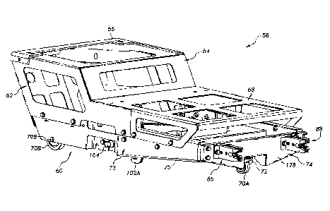
of an original
equipment manufacturer (OEM) van is enlarged or otherwise modified to permit
entry of the
physically limited individual through what is known as the assisted entrance.
Once inside the
vehicle, individuals who use the assisted entrance are often located in a rear
passenger
compai __ intent of the van adjacent to or behind the assisted entrance.
[0005] While these seating locations provide for the transport of the
physically limited
individual, such locations do not always lend themselves to providing good
sightlines which
enable the passenger to see a complete view of the road and the surrounding
scenery.
Consequently, what is needed is a modification to an OEM vehicle which allows
the physically
1
Date Recue/Date Received 2023-04-17
limited individual seated in a wheelchair to be located in the front passenger
compartment, either
as the passenger or as the driver.
SUMMARY
[0006] In one embodiment, there is provided a seat base assembly for a
vehicle.
[0007] In another embodiment, there is provided a removable seat base for a
vehicle
retrofitted to transport a passenger confined to a wheelchair, such that the
vehicle is
interchangeably modified for a use by a passenger or driver confined to a
wheelchair and a
passenger or driver not confined to a wheelchair.
[0008] In accordance with one embodiment, a base assembly has a riser
portion configured
to support a seat; a frame structure coupled to and supporting the riser
portion, the frame
structure defining a first generally planar surface configured to support a
floor section; a seat
dolly coupled to the frame structure, the seat dolly including a plurality of
wheels for moving the
seat assembly from a first position to a second position; a floor base
assembly defining a
substantially planar surface for receiving the plurality of wheels of the seat
dolly as the seat
assembly is moved from the first position to the second position; and a
mounting bracket
configured to releasably lock the seat dolly to the floor base assembly.
[0009] In accordance with still another embodiment, the removable seat
assembly comprises
a base assembly; a seat dolly including a plurality of wheels for moving the
seat assembly from a
first position to a second position; a hook extending from the seat dolly; a
latch assembly having
a mechanical actuator rotatably coupled to the hook; a floor base assembly
defining a
substantially planar surface for receiving the plurality of wheels of the seat
dolly as the seat
assembly is moved from the first position to the second position; and a
mounting bracket
configured to releasably lock the seat dolly to the floor base assembly.
BRIEF DESCRIPTION OF THE DRAWINGS
[0010] The above-mentioned aspects of the present invention and the manner
of obtaining
them will become more apparent and the invention itself will be better
understood by reference
to the following description of the embodiments of the invention, taken in
conjunction with the
accompanying drawings, wherein:
2
Date Recue/Date Received 2023-04-17
[0011] FIG. 1 illustrates an elevational side view of a sport utility
vehicle including an access
ramp.
[0012] FIG. 2 illustrates a top plan sectioned view of a sport utility
vehicle including a
positionable shifter assembly.
[0013] FIG. 3 illustrates a seat assembly.
[0014] FIG. 4 illustrates a seat base assembly for the seat assembly of
FIG. 3.
[0015] FIG. 5 illustrates a floor base assembly.
[0016] FIG. 6 illustrates another embodiment of a floor base assembly.
[0017] FIG. 7 illustrates a portion of the seat base assembly of FIG. 4.
[0018] FIG. 8 illustrates one embodiment of a mounting projection.
[0019] FIG. 9 illustrates a portion of the mounting projection of FIG. 8.
[0020] FIG. 10 illustrates a portion of a seat base assembly including
receivers.
[0021] FIG. 11 illustrates a receiver of FIG. 10.
[0022] Corresponding reference numerals are used to indicate corresponding
parts
throughout the several views.
DETAILED DESCRIPTION
[0023] The embodiments of the present invention described below are not
intended to be
exhaustive or to limit the invention to the precise forms disclosed in the
following detailed
description. Rather, the embodiments are chosen and described so that others
skilled in the art
may appreciate and understand the principles and practices of the present
invention.
[0024] FIG. 1 illustrates a sport utility vehicle (SUV) 10 available from
any number of
United States and foreign manufacturers. In the illustrated embodiment, the
SUV, also called a
crossover vehicle, includes a unibody construction, but other SUV's having a
frame on body
construction, are also included in the present disclosure. Consequently the
use of SUV herein
includes all types and kinds of sport utility vehicles constructed with a body
on frame
construction, a unibody construction, or other constructions. In addition,
while the SUV is
illustrated in FIG. 1, the present disclosure is directed to all passenger
vehicles carrying one or
more passengers, including vans and sedans.
[0025] FIG. 1 illustrates the SUV 10 including a body 12 operatively
coupled to front wheels
14 and rear wheels 16. The SUV 10 includes a unibody construction. A first
passenger side
3
Date Recue/Date Received 2023-04-17
door 18 is located between the front wheels 14 and rear wheels 16 and provides
access to a
passenger for sitting in a front seat of the vehicle adjacent to the driver.
In this position, the
passenger has a clearer view of the road when compared to sitting in a middle
row or back row
of seats of the vehicle.
[0026] The SUV 10 has been modified to include a second passenger side door
20 coupled to
the unibody frame through a mechanical linkage (not shown). In other
embodiments, the side
door 20 is coupled to the unibody frame through a sliding mechanism. In this
embodiment, the
second passenger side door has been modified to slide along a track (not
shown), as opposed to
the manufacturer supplied door which is hinged to swing away from the vehicle,
as is understood
by those skilled in the art. In addition to modifying the door 20 to slide
along the track, an
opening 22 to the interior, in some embodiments, is modified or widened to
provide access to a
passenger seated in a wheelchair. The opening is defined on the sides thereof
by an edge of the
door 20 and the edge of the door 18. The vehicle is further modified to
include a ramp assembly
24 which provides rolling access of the wheelchair from pavement 26 into an
interior 28 of the
vehicle 10. To provide sufficient room for the ramp assembly 24 to be carried
in the vehicle, the
pre-existing floor of the vehicle is removed and a new floor is installed
which is lower than the
old floor. The lowered floor of the vehicle provides a storage location for
the ramp assembly 24
and also increases the headspace for a wheelchaired passenger. The ramp
assembly 24 is
installed at the opening 22 and is movable between the interior of the
vehicle, where it is stored
in some embodiments, and to the exterior for wheelchair access.
[0027] In known modified vehicles, such as modified vans, the middle row of
seats is
removed from the manufacturer supplied vehicle to enable access to a
wheelchair supporting a
passenger. Once the wheelchaired passenger moves into the interior of the
vehicle, the passenger
or caregiver locates the wheelchair in the middle portion of the interior
behind the driver and
passenger seats of the front row. While the wheelchaired passenger is readily
and safely
transported by the vehicle, when located at this position, the passenger can
have difficulty
communicating with the driver and difficulty viewing the road and surrounding
scenery. This
location is therefore often frustrating for many individuals, particularly
those individuals who led
active lives prior to receiving their disability and who continue to be
active. As used herein,
wheelchaired passenger is used to indicate that the individual is making use
of a wheelchair,
whether that use is temporary or permanent.
4
Date Recue/Date Received 2023-04-17
[0028] Over the past few years, the number of wheelchaired individuals who
desire to lead
full active lives has increased. To accommodate such individuals, the SUV has
become a
preferred vehicle of choice, particularly with military veterans who received
disabilities during
their tours of duty. Consequently, the SUV 10 is further modified or
retrofitted as illustrated in
FIG. 2 to provide a location for the wheelchaired passenger to be located in
the front passenger
compaiiment at either a driver side location 30 or a passenger side location
32, next the driver.
To retrofit the vehicle 10, a manufactured SUV is purchased from a dealer or
directly from the
manufacturer, and in one embodiment, the manufacturer supplied center console
is disassembled
or removed from the vehicle. In particular, the original shifter is separated
from other
manufacturer supplied components and reused and located in the front passenger
compaiiment in
a positionable shifter assembly 34, as described herein.
[0029] As can be seen in FIG. 2, the driver side location 30 and the
passenger side location
32 are located in a front passenger compaiiment on either side of the
positionable shifter
assembly 34, which includes a center console 36 and a shifter 38. In this
embodiment, the shifter
assembly 34 is configured to move along a line 40 such that the shifter
assembly 34 is
positionable within the front passenger compaiiment to either increase or
decrease the amount of
usable floor area in either of the driver side location 30 and the passenger
side location 32.
When moved closer to the driver side location 30, the passenger side position
32 is enlarged
sufficiently to accommodate a wheelchair 42. In another embodiment, a seat 44
is removed and
the shifter assembly 34 is moved toward the passenger side position 32 to
accommodate the
wheelchair 42 when located in the driver side location 30. While a
positionable shifter assembly
34 is illustrated, in other embodiments, the original shifter assembly is not
replaced, and remains
fixed in the front passenger compaiiment.
[0030] The vehicle 10 is further retrofitted, in one embodiment, to enable
both the driver side
location 30 and the passenger side location 32 to include one of the
wheelchair 42 or a seat 44. In
the event a seat 44 is desired in one of the locations 30 and 32, a seat
assembly 50 of FIG. 3 is
placed in a recessed area of one of the locations 30 and 32. The seat assembly
50 in other
embodiments is located in both positions, but one or both is removable to
accommodate a
wheelchaired passenger. The recessed area is formed during the retrofit of the
vehicle to lower
the floor. Each of the driver side location 30 and the passenger side location
32 includes the
Date Recue/Date Received 2023-04-17
recessed area in one embodiment. In other embodiments, however, one recessed
area is located
at one of the driver side location 30 and the passenger side location 32, but
not the other.
[0031] FIG. 3 illustrates the seat assembly 50 configured to be located in
the driver side
location 30. While a passenger side seat assembly is not discussed, the seat
assembly 50 for a
passenger side location 32 is substantially similar but is a mirrored
configuration of the driver
side seat assembly.
[0032] As illustrated in FIG. 3, the seat assembly 50 includes a seat 52
mounted to and
supported by a base assembly 54. The base assembly 54 includes a riser 56 upon
which the seat
52 is located. A lower seat base 58 supports the riser 56. In one embodiment,
the seat 52 is
configured to slide along the riser 56 to adjust the seat location within the
driver side location 30.
[0033] As further illustrated in FIG. 4, the lower seat base 58 includes a
seat dolly 60
configured to support a frame structure 62. The frame structure 62 is coupled
to and supports the
riser 56 and the seat 52. The frame structure 62 includes a first portion 64
generally defining a
first support surface 66 and a second portion 68. The first support surface 66
defines a generally
planar support surface configured to support the seat 52 in a level position.
The second portion
68 also defines a generally planar support surface which is configured to
support a floor section
upon which a passenger places their feet. In one embodiment, the second
portion 68 is disposed
slightly lower than a surrounding floor portion such that a floor insert
placed on the second
portion 68 provides a flush surface between the floor insert and surrounding
floor. In different
embodiments, the frame structure 62 includes one or more individual one-piece
parts each of
which are configured to provide a complete frame structure 62.
[0034] The seat dolly 60 supports the frame structure 62 and includes a
plurality of wheels
70A and 70B, which are shown in FIG. 4, and one additional wheel 70C as shown
in FIG. 7.
While the seat dolly 60 embodiment of FIGS. 4 and 7 includes three wheels 70,
in different
embodiments, different numbers of wheels are included. The wheel 70A is
mounted to a swivel
caster 72 at a front end 74 and the wheels 70B and 70C are mounted
respectively on a rod 79B
and 79C.
[0035] As shown in FIG. 4, the seat dolly 60 includes a frame 73 including
a side 75
connected to the front end 74. While not shown in FIG. 4, the seat dolly 60
includes a rear end
coupled to the side 75 and also coupled to a second side 77 of FIG. 7. In
different embodiments,
the frame 73 is made of one or more single piece parts.
6
Date Recue/Date Received 2023-04-17
[0036] FIG. 5 illustrates one embodiment of a floor base assembly 76 which
is located in the
recessed portion of the vehicle 10 and which is configured to fixedly locate
the seat assembly 50
with respect to the vehicle 10. In the illustrated embodiment, the floor base
assembly 76
includes a width 78 and a length 80 which fits similar dimensions of the floor
recess such that
fixing the floor base assembly 76 to the vehicle recess requires reduced
fastening requirements.
The floor base assembly 76 includes a floor section 82 defining a
substantially planar surface
such that the seat assembly 50 is rolled onto the floor section 82 for
locating the seat assembly 50
into position. Since the wheel 70A is caster mounted, the front end 74 of the
dolly 60 is movable
from side-to side to enable alignment of the seat assembly 50 with respect to
the driver side
location 30, where the floor base assembly 76 is located.
[0037] The wheel 70A provides for directional control of the front end 74
such that
movement of the seat assembly 50 toward a front portion 84 engages a first
mounting projection
86 and second mounting projection 88 (see FIG. 4) with a mounting bracket 90
of the floor base
assembly 76. The mounting bracket 90 includes first and second receivers 92
and 94, each of
which is configured to respectively receive the first mounting projection 86
and the second
mounting projection 88. Once the seat assembly 50 has been moved forward to
engage the
projections 86 and 88 to the receivers 92 and 94, the seat dolly 60 is
positioned to be fixed in
place to the floor base assembly 76.
[0038] The floor section 82 includes a first recess 96 and a second recess
98. Each of the
first and second recesses 96 and 98 define a cavity 100 which extends into the
floor section 82
and which are configured to receive a first hook 102A (see FIG. 4) and a
second hook 102B (see
FIG. 7). Each of the hooks 102A and 102B includes a recess 104 which engage a
pin 106 of the
floor section 82. Engagement of the hooks 102 with the pins 106 holds the seat
assembly 50 in
place with respect to the floor base assembly 76.
[0039] FIG. 6 illustrates another embodiment of a floor base assembly 110
which includes a
floor section 112 having a length 114, similar in length to the length 80 of
the floor base
assembly 76 of FIG. 5. A width 116 of the floor section 112 is longer than the
width 78 of the
floor section 82 and is sufficient to provide a driver side locating area 118
and a passenger side
locating area 120. The floor section 112 includes a first, second, third, and
fourth locating
recesses 121, 122, 123, and 124. Each of the recesses defines a cavity and
each is configured to
accept the hooks of the seat dolly 60. Each of the recesses includes a U-
shaped member 126
7
Date Recue/Date Received 2023-04-17
including an engaging pin 128 which is engaged by one of the hooks of the seat
dolly 60. In the
illustrated embodiment, an end of the U-shaped member 126, opposite the
engaging pins 128, is
rotatably coupled to the floor section 112. Engagement of the hook to the
engaging pin 128,
thereby moves the members U-shaped 126 such that an engagement pressure is
applied by the
hook to the U-shaped member 126 to maintain a pressurized contact
therebetween. When not
engaged by the hooks of the seat dolly 60, the U-shaped members move into the
respective
recesses so as not to obstruct items, materials, or persons located on the
floor section 112.
[0040] As with the floor base assembly 76, the floor base assembly 110
includes a mounting
bracket 130, which includes first, second, third and fourth receivers 132,
134, 136, and 138, each
of which is configured to engage one of the mounting projections. For
instance, the first and
second receivers 132 and 134 are configured to receive the first mounting
projection 86 and the
second mounting projection 88 of FIG. 4. If a passenger side seat assembly is
provided, the
passenger side seat assembly includes similar projections each of which is
configured to engage
the receivers 136 and 138.
[0041] The mounting bracket 130 extends from and substantially
perpendicular to floor
section 112. The mounting bracket 130 includes one or more single part pieces
arranged to
provide the receivers. Each of the receivers 132, 134, 136, and 138 define a
recess into which
the mounting projections extend when the seat assembly is fixed in place on
the floor section 112
through engagement of the hooks 102 to the U-shaped members 126. The mounting
bracket 130,
in one embodiment, is connected to the firewall of the vehicle 10. In the
illustrated embodiment,
the bracket 130 includes a first aperture 140 and a second aperture 142 which
receive a connector
to thereby fixedly connect the floor base assembly110 to the firewall.
[0042] FIG. 7 illustrates a portion of the frame 73 of the seat dolly 60
having the front end 74
and the second side 77. The first side 75 and a back bracket are removed for
illustrating further
details of the seat dolly 60. The frame 73 supports a latch assembly 150 which
includes a
mechanical actuator 152 having a first end 154 coupled to a support bracket
156 and a second
end 158 rotatably coupled to the hook 102B at the first end 158. The
mechanical actuator 152, in
one embodiment as illustrated, includes a hydraulic cylinder having a cylinder
rod 160 defining
the second end 158.
[0043] A rod 162 extends from one side to the other side of the frame 73
and is rotatably
supported by the frame 73. An end 164 extends past the first side 75 (see FIG.
4) to be
8
Date Recue/Date Received 2023-04-17
accessible to a user of the seat assembly 50. In the embodiment of FIG. 1, an
actuator 166 is
fixedly coupled to the end 164. At this location, the actuator 166 is between
the driver side area
and passenger side area. Movement of the actuator 166 engages and disengages
the hooks 102A
and 102 B with a respective pin 106 or a respective U-shaped member 126. The
other end (not
shown) of the rod 162 extend into and is supported by a stiffener bracket 165.
In other
embodiments, the actuator 166 is located on an opposite side of the
illustrated seat assembly 60,
between a door and the seat assembly 60.
[0044] Each of the hooks 102A and 102B are fixedly coupled to the rod 162
such that
rotation of the rod 162 about the axis thereof moves the hooks 102 into and
out of engagement
with the pins or U-shaped members. Rotation of the rod 162 in a
counterclockwise direction as
illustrated moves hooks 102A away from the pins or U-shaped members to enable
movement of
the seat assembly 50 from the fixed location. Rotation of the rod 162 in the
clockwise direction
moves the hooks 102A toward the pins or U-shaped members to fix the location
of the seat
assembly 50 with the base.
[0045] FIG. 8 illustrates one embodiment of the mounting projection 86 of
FIG. 4.
Mounting projection 88 is similarly configured as projection 86 and the
discussion with regard to
projection 86 of FIG. 8 similarly describes the projection 88. As illustrated
in FIG. 8, the
mounting projection 86 includes a first mounting bracket 170 and a second
mounting bracket
172. Each of the brackets 170 and 172 are similarly configured and include a
right angle
configuration in which a first portion 174 includes an aperture through which
a connector 176 is
inserted into a front bracket 178 of front end 74 of FIG. 4. A second portion
180 extends from
the first portion 174 at a substantially right angle. The second portion 180
of each of the
brackets 170 and 172 are spaced a distance apart to define a space
therebetween in which a
resilient member 182 is located. Each of the second portions 178 are
configured to support a
guide piece 184, which are each coupled to one of the respective brackets 170
and 174.
[0046] As seen in FIGS. 8 and 9, each of the guide pieces 184 include a
groove 186
configured to accept a pin 188 of the receivers 132 and 134 as illustrated in
FIG. 6 and as further
described in FIGS. 10 and 11. The groove 186 includes a front portion 190
configured to guide
the receivers into engagement with the pin 188. The front portion 190 includes
a first guide
feature 192 which provides a first ramp structure to guide the projection 86
and 88 into
engagement with the pin 188. A second guide feature 194 includes a second ramp
structure to
9
Date Recue/Date Received 2023-04-17
guide the projections 86 and 88 into the appropriate receiver through guiding
contact with a side
wall 196 and 198 (see FIG. 10). If the alignment of the seat dolly 60 is
slightly offset from the
receivers, the first and second guide features 192 and 194 direct the mounting
projection into
alignment with the receivers as the seat dolly 60 is moved forward to locate
the pins 188 into the
groove 186.
[0047] The resilient member 182 includes a channel 200 having a width
dimension less than
a width dimension of the groove 186. The width dimension of the groove 186 is
the same
dimension or slightly larger as a diameter of the pin 188. The width dimension
of the channel
200, however, is less than the diameter of the pin 188. Consequently as the
dolly 60 is moved
toward the receivers, the channel 200 of resilient member 182 expands from the
engagement
with the pin 188. The pin compresses with structure of the member 182 and
provides a press fit
with the pin 188. Once the dolly 60 is aligned with the base, movement of the
actuator 166
engages the channel 200 into further engagement with the pin 188. The
compression fit between
the channel 200 and the pin 188 restricts movement of the dolly 60 with
respect to the base and
absorbs road conditions to provide a passenger with a relatively vibration-
free anti-rattle seating
arrangement.
100481 In one embodiment, the resilient member 182 is made of rubber, a
rubber compound,
or a reinforced rubber. In additional embodiments, the guide pieces 184 are
made of a plastic or
a reinforced plastic. In other embodiments, the resilient member 182 and guide
pieces 184 are
made of a single one piece molded part having a similar shape to the multiple
piece projection.
The material of the single piece part is selected to provide for the features
described above.
[0049] FIGS. 10 and 11 illustrate the receivers 132 and 134 (see FIG. 60,
each of which is
similarly configured. As described above, each of the receivers includes the
pin 188, the side
wall 196, and the side wall 198. Each of the side walls 196 and 198 are
similarly configured to
define a recess into which the projections are received. The recess includes a
floor 202 and a
ceiling 204, each of which is connected to the side walls 196 and 198. Each of
the side walls 196
and 198 include a first planar portion 206 and a second planar portion 208,
each of which are
inclined with respect to a central axis 210. The angle of the first planar
portion 206 with respect
to the central axis 210 is greater than the angle of the second planar portion
208 with respect to
the central axis 210, such that insertion of the projection into a recess is
progressively directed to
a central location within the recess.
Date Recue/Date Received 2023-04-17
[0050] As described herein, the seat assembly provides an improved
configuration for a
retrofitted vehicle. In particular, the seat assembly, while described as
being located in either the
driver side location or the front passenger side location, in other
embodiments, the seat assembly
is located in one or more other passenger locations within a vehicle. The seat
assembly,
therefore, provides a configurable vehicle designed to accommodate individuals
of different
physical capabilities. In addition, the vehicle is configurable to a vehicle
seating only physically
capable individuals, in the event that the physical limited individual
continues to improve and no
longer requires wheelchair transportation.
[0051] While exemplary embodiments incorporating the principles of the
present invention
have been disclosed herein, the present invention is not limited to the
disclosed embodiments.
Instead, this application is intended to cover any variations, uses, or
adaptations of the invention
using its general principles. Further, this application is intended to cover
such departures from
the present disclosure as come within known or customary practice in the art
to which this
invention pertains and which fall within the limits of the appended claims.
11
Date Recue/Date Received 2023-04-17