Note: Descriptions are shown in the official language in which they were submitted.
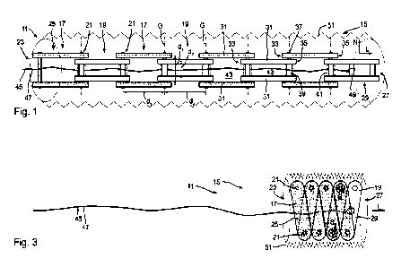
Chain lock and chain for a chain lock
The invention relates to a chain lock, in particular to a two-wheeler chain
lock, and
to a chain for a chain lock, in particular for a two-wheeler chain lock.
To secure two-wheelers or other movable objects against theft, it is known to
connect the respective object to an immovable object by means of a lock. In
this
respect, the lock generally has an elongate latch element which is ideally
guided
through an opening of the object to be secured and through an opening of the
immovable object or around the immovable object and is then received at and
locked to a lock body of the lock such that a structure results that is closed
in a
ring shape and that can subsequently be unlocked and opened again in a regular
manner only by means of an associated secret code, for example, a key or a
code.
This latch element may, for example, be a typically U-shaped closing hoop of a
hoop lock. Such a closing hoop is rigid. For this reason, it may only have a
very
limited length in order not to be too bulky for a simple taking along. This
has the
result that the movable object to be secured has to be positioned very close
to the
immovable object to which it is to be secured in order to be able to be
secured
thereto by means of a hoop lock.
A more flexible positioning of the object to be secured may be achieved by a
lock
having a longer latch element that is then, however, preferably not rigid or
at least
not rigid throughout, but may be folded to be able to be transported in a
compact
shape. Such a latch element may, for example, be formed by a rope, a cable, or
a
chain.
In addition to a flexible applicability, it is in this respect naturally also
important that
the latch element is designed as secure as possible against a separation or a
CA 03197383 2023- 5-3
2
breaking open. Cable locks, in particular spiral cable locks, may indeed have
particularly long latch elements that may e.g. be formed from wire ropes, but
that
often do not offer a particularly high level of security. In comparison
thereto, the
use of a link chain comprising round or oval chain links engaging into one
another
as the latch element may offer a higher security since the link chain as a
whole is
indeed flexible, but the individual chain links may be rigid and may thus be
formed
from a particularly hard material, e.g. from a hardened steel. However, the
comparatively high weight may be a disadvantage of a link chain as the latch
element.
The weight may play a rather minor role for the securing of heavy motorcycles.
However, especially with bicycles, in particular e.g. high-quality lightweight
racing
bikes, a low weight is also important in addition to a high security against
being
broken open. In particular in this connection, jointed bar locks are
particularly
advantageous whose latch element is formed by rigid flat-elongate links that
are
coupled to one another in an articulated manner and that are arranged offset
in
parallel from one another such that they may be folded in the manner of a
yardstick to form a compact package. These rigid jointed bars as well as the
articulated joints between the jointed bars may in this respect offer a high
security
against being broken open while the weight remains comparatively low. In
addition, a jointed bar lock may indeed have a long length, in particular in
comparison with a hoop lock, but may nevertheless be folded in a particularly
compact manner and may thus be easily transportable.
However, to be able to be easily folded like a yardstick with a few hand
movements, the length of the individual jointed bars may not be too short and
the
number of jointed bars may not be too high. This has the result that the
jointed bar
arrangement may only have a polygonal course of a few straight sections, but
may
not be led around tight curves. In particular in confined environments, e.g.
when a
plurality of bicycles are connected to a single lamppost, it is, however,
CA 03197383 2023- 5-3
3
advantageous if the latch element of the respective lock may also have tightly
curved courses in order to be particularly flexibly usable.
It is an object of the invention to provide a chain lock, in particular a two-
wheeler
chain lock, and a chain for a chain lock, in particular for a two-w heeler
chain lock,
that may each be used in a particularly flexible manner, that may be simply
folded
in a compact manner for the transport, and that in this respect simultaneously
have a high security against being broken open and a comparatively low weight.
The object is satisfied by a chain lock having the features of claim 1 and by
a
chain having the features of claim 4.
Advantageous embodiments of the invention result from the dependent claims,
from the present description, and from the Figures.
The chain in accordance with the invention is configured for a chain lock, in
particular for a two-wheeler chain lock, such that it is in particular
suitable to be
used as the latch element of a chain lock. For this purpose, the chain may be
correspondingly configured, in particular at its respective ends or at least
one of
the ends, for example by providing one or more elements of a locking mechanism
or one or more elements cooperating with a locking mechanism, e.g. a bolt,
there.
However, this is not absolutely necessary. For provision may also be made that
certain sections of the chain that are not necessarily configured in a
particular
manner for a locking may be locked to a lock body of the chain lock. For this
purpose, the lock body may, for example, have a locking receiver in which a
respective one of these sections may be received and may then be secured
against a departure from the locking receiver by means of the locking
mechanism
that is in particular formed at the lock body.
CA 03197383 2023- 5-3
4
In accordance with the invention, the chain comprises a serial arrangement of
consecutive links, wherein the links are coupled to one another via a
respective
articulated joint between one another and may be pivoted relative to one
another
about a joint axis, which is in parallel with a normal direction, of the
respective
articulated joint, i.e. the links of each pair of two directly consecutive
links of the
arrangement are coupled to one another via a respective articulated joint and
are
pivotable relative to one another about a joint axis, which is in parallel
with a
normal direction, of the respective articulated joint.
The serial arrangement therefore comprises a plurality of links that are
arranged in
a specific sequence. The arrangement may in particular extend from a first end
link up to a second end link. Each link of the arrangement, with the exception
of
the two end links, is in each case coupled to the link preceding it along the
sequence and to the link following it along the sequence via a respective
articulated joint. The first end link, which is not preceded by a link along
the
sequence, may in this respect be coupled only to the link of the arrangement
which follows it along the sequence and the second end link, which is not
followed
by a link along the sequence, may in this respect be coupled, via an
articulated
joint, only to the link of the arrangement which precedes it along the
sequence. In
general, however, even further elements of the chain, in particular also
further
links, may be connected to one or to both ends of the arrangement and may be
coupled in an articulated manner or in another manner to the respective end.
The
arrangement, for example, comprises at least four links, preferably at least
ten
links, in particular at least 16 links.
All the articulated joints, which each couple two consecutive links of the
arrangement, each have a joint axis about which the links coupled by the
respective articulated joint are pivotable relative to one another. All these
joint
axes are in this respect aligned in parallel with a normal direction and are
thus also
aligned in parallel with one another. The designation of the common
orientation of
CA 03197383 2023- 5-3
5
the joint axes as a normal direction in this respect only serves for the
conceptual
differentiation from other directions and is not intended to imply that either
a
restriction to a particular spatial direction or a particular property of the
direction is
"normal".
The articulated joints are in particular each configured such that the two
links
coupled by the respective articulated joint are pivotable relative to one
another
only about said joint axis of the articulated joint and have no other kind of
relative
movability. In other words, apart from a possible and generally not completely
avoidable clearance, e.g. an offset along the joint axis and smaller tilting
movements perpendicular to the joint axis, the articulated joints each have
only
one degree of freedom, namely the pivotability about the joint axis. Since all
the
links are thus pivotable about mutually parallel joint axes, the movability of
the
links, and thus of the total mentioned arrangement, may overall be limited to
movements within a spatial region that is bounded by two planes perpendicular
to
the normal direction.
The links of the arrangement may each extend along a longitudinal extent from
a
first end to a second end of the respective link. In this respect, the
articulated joint
for coupling to the respective preceding link, if such a one is present, may
in
particular be provided at the first end of a respective link and the
articulated joint
for coupling to the respective following link, if such a one is present, may
be
provided at the second end of a respective link. The direction of the
longitudinal
extent of the respective link may then be defined by a straight line that
connects
the two articulated joints, in particular perpendicular to the normal
direction. The
longitudinal extent of a respective link may, for example, amount to some few
centimeters, e.g. be in a range between 2 cm and 10 cm, preferably in a range
between 3 cm and 8 cm, in particular in a range between 4 cm and 6 cm.
CA 03197383 2023- 5-3
6
The links of the arrangement may generally be of the same construction as one
another or may also be formed differently from one another. It is in
particular also
possible for all the links to differ from one another with respect to their
design, for
instance with respect to their respective longitudinal extent and/or their
respective
extent along the normal direction. The joint axes of the articulated joints
are,
however, preferably at least regularly spaced apart from one another. In
accordance with an advantageous embodiment, all the pairs of two respective
articulated joints that follow one another along the serial arrangement have
the
same spacing between their joint axes. In this respect, all the links of the
arrangement may in particular have the same longitudinal extent. However, said
spacing may also vary depending on the embodiment.
Said serial arrangement may comprise first links and second links that follow
one
another in an alternating manner along the sequence of the links of the
arrangement. The articulated joints therefore each couple a first link and a
second
link to one another, namely either a first link to a second link following it
(along the
sequence of the links of the arrangement) or a second link to a first link
following it
(along the sequence of links of the arrangement). The designation of the links
as
first links and second links in this respect primarily serves for the
conceptual
differentiation of the links on the basis of their respective position within
the serial
arrangement. The links at a position having an odd ordinal number (1st, 3rd,
etc.)
may in particular be the first links, while the links at a position having an
even
ordinal number (2nd, 4th, etc.) are the second links. In this respect, said
first end
link is one of the first links of the arrangement. Depending on the total
number of
links of the arrangement, the second end link of the arrangement may be one of
the first links or one of the second links of the arrangement. Where a first
link of
the arrangement or a second link of the arrangement is spoken of in the
following,
this in each case serves to refer to one or more links at a corresponding
position
within the arrangement.
CA 03197383 2023- 5-3
7
The first links do not necessarily have to differ from the second links in
this
respect. Furthermore, neither the first links nor the second links are in each
case
necessarily of the same kind as another. However, the first links and/or the
second
links are each preferably substantially of the same kind as one another, in
particular of the same construction (possibly with the exception of the first
and/or
the second end link of the arrangement). Furthermore, it may be expedient for
the
first links to differ from the second links.
Said links of the arrangement may generally again be further subdivided,
wherein
the sub-links may be movable, in particular pivotable, relative to one
another.
However, all the links of the arrangement are preferably each rigid. The links
of the
arrangement may in particular comprise a hardened metal as the material.
Since the chain comprises said serial arrangement of links pivotably coupled
to
one another, the chain is in this respect at least partly configured,
preferably at
least substantially completely configured, as a sprocket chain. Such a
sprocket
chain of links connected by articulated joints is to be distinguished from a
link
chain of links that engage into one another in a ring shape and that may each
be
pivoted relative to the preceding or following link largely freely in all
three spatial
directions and may also be displaced to a limited extent.
In accordance with the invention, said serial arrangement may be folded into a
compact storage configuration in which, at each of the articulated joints, the
two
links coupled to one another via the respective articulated joint are pivoted
relative
to one another about the joint axis of the respective articulated joint to
such an
extent that they enclose the smallest possible angle within the framework of
their
relative pivotability. The angle enclosed by the two links is in this respect
considered as the smaller of the two angles that may be defined between the
two
links and that together result in a full angle of 360 . In addition, the
enclosed angle
CA 03197383 2023- 5-3
8
is considered in terms of magnitude and may therefore generally not be less
than
0 .
In this respect, the links of the arrangement in the compact storage
configuration,
which are coupled to a respective preceding link via a respective link, may be
pivoted in an alternating manner in a first pivot direction and in a second
pivot
direction opposite to the first pivot direction relative to the respective
preceding link
about the joint axis of the respective articulated joint to such an extent
that they
enclose the smallest possible angle within the framework of their relative
pivotability.
When the links of the arrangement, as explained above, are distinguished as
first
links and second links, at each articulated joint that couples a first link of
the
arrangement to a second link of the arrangement preceding it (along the
sequence
of links of the arrangement), the first link may in particular be pivoted in
the first
pivot direction relative to the second link preceding it about the joint axis
of the
respective articulated joint to such an extent that the two links enclose the
smallest
possible angle within the framework of their relative pivotability and, at
each
articulated joint that couples a second link of the arrangement to a first
link of the
arrangement preceding it (along the sequence of links of the arrangement), the
second link may be pivoted relative to the first link preceding it in the
second pivot
direction about the joint axis of the respective articulation to such an
extent that
the two links enclose the smallest possible angle within the framework of
their
relative pivotability.
In all of these cases, said smallest possible angle is related to the
pivotability of
the two links of the arrangement enclosing the angle relative to one another,
i.e. to
how far the one link may be pivoted relative to the other link. In other
words, the
angle is the smallest possible angle within the framework of the relative
pivotability
of the two respective links in that it may either generally not become smaller
since
CA 03197383 2023- 5-3
9
the two links enclose an angle of 0 or in that it corresponds to a limit of
the
relative pivotability beyond which the two links may not be pivoted toward one
another. This will be explained in more detail in the following.
In general, the relative pivotability of two consecutive links of the
arrangement
coupled to one another via a respective articulated joint may be unrestricted
such
that a full rotation of the one link relative to the other link about the
joint axis is
possible.
However, the relative pivotability of two consecutive links coupled to one
another
via a respective articulated joint may also be limited to a specific pivot
range. The
limitation may in particular arise from the fact that the links meet one
another on
the pivoting and therefore may not be pivoted up to and into the same
orientation
relative to the joint axis of the respective articulated joint, which would
correspond
to an enclosed angle of 00. The angular extent of the limited pivot range is
in this
respect preferably identical for all said articulated joints. For example, the
angular
extent may be in the range between 300 and 3500; it is preferably in the
range
between 320 and 345 ; it may in particular amount to approximately 330 ,
approximately 3350, or approximately 3400. Compared to an extended position in
which two mutually coupled links are each arranged along a straight line with
respect to their longitudinal extent, the one of the two links may in
particular be
pivotable relative to the other by a maximum of less than 1800. For example,
the
one link may be pivoted relative to the other at a maximum by an angle in the
range between 1500 and 175 , preferably at a maximum by an angle in the range
between 1600 and 172.5 , in particular at a maximum by an angle of
approximately
165 , approximately 167.5 , or approximately 170 .
Two cases may therefore be distinguished: Provided that two links of the
arrangement coupled to one another via a respective articulated joint may be
pivoted relative to one another into a position in which they enclose an angle
of 00
,
CA 03197383 2023- 5-3
10
i.e. face in the same direction from the joint axis of the respective
articulated joint,
said smallest possible angle within the framework of the relative pivotability
of the
two links corresponds to this angle of 00, and indeed irrespectively of
whether the
relative pivotability of the two links is otherwise limited or not. If, in
contrast, the
relative pivotability of two links of the arrangement coupled to one another
via a
respective articulated joint is limited such that they may not adopt such a
position,
said smallest possible angle within the framework of the relative pivotability
of the
two links corresponds to one of the two boundaries of the pivot range to which
the
relative pivotability of the two links is limited, in particular to that one
of the two
boundaries at which the two links enclose the angle of smaller magnitude. Said
smallest possible angle may in this respect, for example, be less than or
equal to
30 , preferably less than or equal to 25 , in particular less than or equal to
20 , for
example, amount to approximately 15 .
The fact that two links of the arrangement, which are coupled to one another
via a
respective articulated joint, meet one another on the pivoting, and their
relative
pivotability is thus limited, may in particular result in that two or more
links of the
arrangement at least partly adopt the same position along the normal
direction.
Provision may, for example, be made that, at each articulated joint that
couples a
respective link to a link preceding it, the respective link and the link
preceding it at
least partly adopt the same position along the normal direction.
Two links that at least partly adopt the same position along the normal
direction do
not necessarily have to extend over the same region along the normal
direction,
but may have different extents with respect to the normal direction and/or may
be
offset relative to one another along the normal direction, but only to the
extent that
they still overlap with respect to the normal direction. In this respect, such
an
embodiment in particular differs from jointed bar locks whose links are each
formed by a single jointed bar and, with respect to the direction with which
the joint
axes of the articulated joints coupling the jointed bars are aligned in
parallel, are
CA 03197383 2023- 5-3
11
arranged offset from one another similarly to the links of a yardstick such
that they
do not overlap along this direction, but have different positions and such
that two
consecutive jointed bars may consequently each be pivoted freely past one
another.
Since two links that at least partly adopt the same position along the normal
direction overlap with respect to the normal direction, there is thus always a
plane
perpendicular to the normal direction for two such links that intersects both
links. In
accordance with a preferred embodiment, provision may in particular be made
that
there is a plane perpendicular to the normal direction that intersects all the
links of
the arrangement. The extent of a respective link along the normal direction
may in
this respect be defined by the spacing, in particular the outer spacing, of
two link
plates of the respective link (if the respective link has more link plates: of
the two
outermost link plates of the respective link) such that a plane perpendicular
to the
normal direction intersects the respective link when the plane extends between
the
two link plates, in particular between their respective outer sides.
Unless one of two links of the arrangement that are coupled to one another via
a
respective articulated joint and that at least partly adopt the same position
along
the normal direction may be passed through the other (for instance through a
passage opening of the other), the links meet one another at some point when
they are pivoted toward one another relative to one another such that their
relative
pivotability is limited and the smallest possible angle they may enclose
within the
framework of their relative pivotability corresponds to that angle at which
they
meet. For this reason, the serial arrangement of the chain in accordance with
the
invention or of the chain of the chain lock in accordance with the invention
may not
be folded in the manner of a yardstick when the smallest possible angle that
two
consecutive links of the arrangement may enclose within the framework of their
relative pivotability is greater than 00. Nevertheless, the storage
configuration may
also be comparatively compact in this case, in particular if, as explained
above,
CA 03197383 2023- 5-3
12
the links of the arrangement in the storage configuration are pivoted in an
alternating manner in a first pivot direction and a second pivot direction
opposite
thereto relative to the respective preceding link about the joint axis of the
respective articulated joint such that the arrangement has a zigzag-like
course in
its storage configuration.
In this respect, in the storage configuration, all the angles between a
respective
(first) link, which is pivoted in the first pivot direction relative to the
link preceding it,
and the (second) link of the arrangement preceding said respective (first)
link may
be identical to one another. Moreover, in the storage configuration, all the
angles
between a respective (second) link, which is pivoted in the second pivot
direction
relative to the link preceding it, and the (first) link of the arrangement
preceding
said respective (second) link may be identical to one another. Furthermore, in
the
storage configuration, all the angles between a respective link and the link
of the
arrangement preceding it may be identical to one another.
Furthermore, when the links of the arrangement, as explained above, are
distinguished as first links and second links, in the storage configuration,
all the
first links of the arrangement may be aligned in parallel with one another and
may
be arranged offset from one another along a longitudinal extent of the
arrangement folded in a compact manner perpendicular to the normal direction;
the first links are in this respect preferably not arranged offset from one
another
along the normal direction, but all have the same position with respect to the
normal direction. Moreover, in the storage configuration, all the second links
of the
arrangement may be aligned in parallel with one another and may be arranged
offset from one another along a longitudinal extent of the arrangement folded
in a
compact manner perpendicular to the normal direction; the second links are in
this
respect preferably not arranged offset from one another along the normal
direction, but all have the same position with respect to the normal
direction. When
both the first links and the second links are in each case aligned in parallel
with
CA 03197383 2023- 5-3
13
one another in the storage configuration, the direction in which the first
links are in
this respect aligned in parallel with one another and the direction in which
the
second links are in this respect aligned in parallel with one another are
different
from one another. The two directions may, for example, enclose an angle
between
them in the range between 100 and 600, in particular an angle in the range
between 15 and 40 , preferably an angle of approximately 20 , 25 , or 30 .
In the storage configuration, the first links of the arrangement may
furthermore
contact one another laterally, i.e. in a direction perpendicular to the normal
direction and transverse to the longitudinal extent of the respective link,
and/or the
second links of the arrangement may contact one another laterally, i.e. in a
direction perpendicular to the normal direction and transverse to said
longitudinal
extent of the respective link. The pivotability of a respective first and/or
second link
may in particular be limited precisely by the fact that it laterally impacts
the
respective next-but-one preceding or following link of the arrangement if such
a
one is present.
In addition to the compact storage configuration, the arrangement may also
have
an extended longitudinal configuration. The extended longitudinal
configuration
may in particular be defined in that the arrangement therein extends along a
longitudinal direction perpendicular to the normal direction, and/or in that
the joint
axes of all the articulated joints that couple the two respective links of the
arrangement are arranged therein along a longitudinal direction (in particular
said
longitudinal direction) perpendicular to the normal direction, and/or in that
a first
end of the arrangement and a second end of the arrangement opposite thereto
are
spaced apart from one another at a maximum therein, i.e. as far as possible
within
the framework of the pivotability of the links of the arrangement relative to
one
another.
CA 03197383 2023- 5-3
14
The compact storage configuration may have a greatly reduced length, in
particular in comparison with the longitudinal configuration described. The
chain
may thereby be particularly easy to stow and to transport. For example, a
pocket
may be provided for the chain which is adapted to the dimensions of the chain
in
the storage configuration and in which the chain may therefore be received in
a
flush manner.
The chain in accordance with the invention further comprises a pulling device
which extends along said serial arrangement and by means of which a first end
of
the arrangement and a second end of the arrangement opposite thereto may be
pulled toward one another such that the arrangement is brought into the
compact
storage configuration by the pulling device.
Said first end of the arrangement may, for example, be said first end link of
the
arrangement or a part thereof. Said second end of the arrangement may, for
example, be said second end link of the arrangement or a part thereof. An end
section that forms the first end of the arrangement may in particular be
formed at
the first end link. In addition, an end section that forms the second end of
the
arrangement may be formed at the second end link. The end section may in each
case, for example, be formed by a free end of the respective end link, i.e. an
end
that is not coupled to any other of the links of the arrangement.
Alternatively
thereto, the end section may in particular also be formed by the articulated
joint
between said first end link and the link of the arrangement following it, or
between
said second end link and the link of the arrangement preceding it. The pulling
device may in particular be connected to the end section of one of the two end
links or also to the end sections of both end links.
The fact that the pulling device extends along the arrangement may in
particular
comprise that the pulling device extends along each link of the arrangement,
for
example, is guided by each of the links of the arrangement, extends through
each
CA 03197383 2023- 5-3
15
of the links of the arrangement, and/or surrounds each of the links of the
arrangement.
The pulling device is configured such that the first end of the arrangement
and the
second end of the arrangement may be pulled toward one another by means of
the pulling device. For this purpose, the pulling device does not necessarily
have
to engage at both ends of the arrangement. For example, said property of the
pulling device may comprise that when the first end of the arrangement is
fixedly
held, the second end of the arrangement may be pulled toward the first end of
the
arrangement by means of the pulling device, and/or may comprise that when the
second end of the arrangement is fixedly held, the first end of the
arrangement
may be pulled toward the second end of the arrangement by means of the pulling
device. For this purpose, it may be sufficient for the pulling device to
engage at
one of the two ends of the arrangement, in particular to be fastened to at
least one
of the two ends of the arrangement. The pulling of the one end of the
arrangement
toward the other end of the arrangement is to be understood as a relative
movement between the two ends. The first and second end of the arrangement
may therefore, for example, also be pulled toward one another by means of the
pulling device in that one of the two ends is held in a substantially
stationary
manner by means of the pulling device and the other end is moved, e.g.
dropped,
toward this one end.
The first end and the second end of the arrangement may be pulled toward one
another in a specific manner by means of the pulling device, namely such that
the
arrangement is thereby brought into the compact storage configuration. The
pulling device is in particular configured such that, in that the first and
second end
of the arrangement are pulled toward one another by means of the pulling
device,
it is substantially inevitably simultaneously brought about that the
arrangement
adopts its storage configuration. For this purpose, one or more, in particular
all, of
the links of the arrangement may be correspondingly guided by the pulling
device
CA 03197383 2023- 5-3
16
on the pulling toward one another of the ends of the arrangement such that the
pulling device folds the arrangement into the storage configuration.
Many different possibilities of a cooperation of the pulling device with the
arrangement or with at least some links of the arrangement are conceivable,
which
has the result that the arrangement is brought into its storage configuration
on a
pulling of the two ends of the arrangement toward one another. In this
respect, it is
in each case essential that the pulling device, by means of which the pulling
takes
place, is specifically configured to at least largely ensure at the same time
that not
only the ends of the arrangement are moved toward one another, but the
arrangement as a whole with its links following one another from the first end
to
the second end of the arrangement is in this respect folded in an orderly
manner,
namely such that, in accordance with the storage configuration, at each of the
articulated joints, the links coupled to one another via the respective
articulated
joint are pivoted relative to one another to such an extent that they enclose
the
smallest possible angle within the framework of their relative pivotability.
For this
purpose, the pulling device may in particular be configured to urge the links
of the
arrangement relative to the respective preceding link in an alternating manner
in a
first pivot direction and in a second pivot direction opposite thereto and/or
to block
them in an alternating manner against a pivoting in the second pivot direction
or in
the first pivot direction.
The design of the chain in accordance with the invention - in particular the
foldability into the compact storage configuration as well as the pulling
device
provided for a simple folding - makes it possible that the chain may have a
large
number of comparatively short links and may thus also be laid around tight
curves,
but is nevertheless comfortably foldable in a compact manner to be stowed or
to
be transported. In this respect, a chain of said kind, in particular by rigid
links
composed of a hard material and fixed articulated joints, may have a high
security
against being broken open and a comparatively low weight at the same time.
CA 03197383 2023- 5-3
17
In accordance with an advantageous embodiment, the pulling device comprises an
elongate pulling element, in particular a rope-like pulling element, that
extends
along the arrangement. The pulling element may in particular be fixedly
connected
to the second end of the arrangement, e.g. to said end section, such that the
second end of the arrangement may be pulled toward the first end of the
arrangement via the pulling element. Provided that the chain extends beyond
the
second end of the arrangement, the pulling element may likewise extend beyond
the second end of the arrangement up to a section of the chain or of the
respective
chain lock having the chain, e.g. up to a lock body of the chain lock, to
which it is
fixedly connected such that, by pulling at the pulling element, this section
and via it
at least indirectly also the second end of the arrangement may be pulled
toward
the first end of the arrangement.
The pulling element may, for example, be configured as a rope, a string, or a
cord
and may comprise a fiber, a plastic, and/or a metal as the material. The
pulling
element may, for example, be a pulling rope. The pulling element may in
particular
be configured as a wire rope or a steel cable that preferably has a plastic
jacket.
The pulling device may also comprise more than one pulling element. In this
respect, a plurality of pulling elements may extend along said arrangement.
Alternatively or additionally, provision may, however, also be made that the
chain
comprises a plurality of arrangements along each of which one or more pulling
elements extend. The possibilities described or described in the following of
how a
single pulling element may be formed also apply in a corresponding manner to a
plurality of pulling elements. In this respect, the plurality of pulling
elements may
each be of the same kind. However, it is also possible that different pulling
elements are formed in one or more different ways, in particular in different
ones of
the ways described.
CA 03197383 2023- 5-3
18
In accordance with an advantageous embodiment, the pulling element has a
slalom-like course about the joint axes of the articulated joints. In this
respect, the
course is in particular slalom-like in that the pulling element passes the
articulated
joints in accordance with their sequence along the serial arrangement of
consecutive links in an alternating manner in the one direction of rotation
and the
other direction of rotation relative to the joint axis of the respective
articulated joint.
In other words, the pulling element extends past the joint axis of each second
articulated joint at the one side (e.g. at the right) and past the joint axis
of each of
the remaining articulated joints at the other side (e.g. at the left). When
the links of
the arrangement are distinguished as first links and second links as explained
above, the pulling element may in particular pass the joint axes of the
articulated
joints which connect a first link to a subsequent second link in the
respective
direction of rotation that corresponds to said first pivot direction, while
the pulling
element passes the joint axes of the articulated joints which connect a second
link
to a subsequent first link in the respective direction of rotation that
corresponds to
said second pivot direction.
When the arrangement is in said extended longitudinal configuration, the
pulling
element consequently winds about the joint axes. In contrast, in the compact
storage configuration, the articulated joints which each connect a first link
to a
subsequent second link may, for instance due to the zig-zag course described,
all
be arranged at one side of the compact package into which the arrangement is
folded in the storage configuration, and the articulated joints which each
connect a
second link to a subsequent first link may be arranged at the side opposite
thereto
while the pulling element extends between these two sides. The pulling element
may then therefore also have an at least largely straight course that is,
however,
nevertheless slalom-like with respect to the joint axes since the pulling
element
extends past the joint axis of each second articulated joint at the one side
and past
the joint axis of each of the remaining articulated joints at the other side.
CA 03197383 2023- 5-3
19
The slalom-like course, in which the pulling element passes the joint axes of
the
articulated joints in an alternating manner in opposite directions of
rotation, may
advantageously have the result that, on a pulling of the pulling element, the
links of
the arrangement are correspondingly pivoted in an alternating manner in the
one
and in the other pivot direction with respect to the respective preceding
link. The
slalom-like course therefore causes - or thus in any case contributes to - the
arrangement being able to be brought into the storage configuration by means
of
the pulling device.
The pulling element is preferably not only basically arrangeable in said
slalom-like
course or may simply randomly have said slalom-like course, but the slalom-
like
course is fixedly predefined for the pulling element. The pulling element may
in
particular for this purpose be guided at the arrangement, in particular at the
links of
the arrangement, such that it has the slalom-like course.
In accordance with a further advantageous embodiment, a winding mechanism is
provided at the pulling element by means of which the pulling element may be
wound up. In other words, the winding mechanism is configured to wind up the
pulling element. This may in particular be expedient in order to wind up an
excess
of the pulling element, by which the pulling element projects over the folded
arrangement or over the chain, after a folding of the arrangement into the
compact
storage configuration. In this respect, the winding mechanism is in particular
useful
when the pulling element itself is at least largely inelastic.
The winding mechanism may be formed as a part of the pulling device of the
chain. Furthermore, the winding mechanism may be arranged at, in particular
in,
the lock body of the chain lock at which the chain is or may be provided
and/or
may be formed as part of the lock body.
CA 03197383 2023- 5-3
20
The winding mechanism may comprise a drive unit that is configured to drive
the
winding mechanism to wind up the pulling element. In this respect, the winding
mechanism may be configured to be adjusted between an activated state, in
which
the winding mechanism winds up the pulling element driven by the drive unit,
and
a deactivated state in which the drive effected by the drive unit is suspended
(e.g.
compensated or blocked). In this respect, provision may be made that the
pulling
element may still at least be unwound in the deactivated state, namely in
particular
by manually pulling the pulling element in the direction away from the winding
mechanism. However, it may also be the case that an unwinding of the pulling
element is blocked in the deactivated state, whereby it may further be
possible to
secure the arrangement in its compact storage configuration. The winding
mechanism preferably automatically adopts the deactivated state as long as it
is
not adjusted into the activated state by a user of the respective chain lock.
The drive unit may in particular be configured as a preloading apparatus whose
preload may drive the winding up of the pulling element. For this purpose, the
preloading apparatus may comprise a spring, for example. Due to a manual
unwinding of the pulling element, the preloading apparatus is in this respect
advantageously in each case at least substantially preloaded again by the
amount
that was previously applied for the winding up of the pulling element such
that the
preloading apparatus may always provide sufficient drive for the winding up of
the
pulling element.
The winding mechanism may in particular be configured in the manner of the
mechanism of a measuring tape that may be rolled up. In addition to a
preloading
apparatus as the drive unit, such a winding mechanism further comprises an
actuation element and is configured to be adjusted between the activated state
and the deactivated state by means of the actuation element. The actuation
element may in particular be configured in the form of a push button. By
pressing
the push button, the winding mechanism may then be adjusted into the activated
CA 03197383 2023- 5-3
21
state and the excess part of the pulling element may thereby be easily and
quickly
wound up.
In accordance with a further advantageous embodiment, the pulling element is
elastic. The pulling element may in particular be configured as an elastic
pulling
rope, as a tension cable, as a tension rubber, or as an elastic band. However,
the
pulling device may also comprise a non-rope-like elastic pulling element, for
example an elastic jacket, in particular an elastic hose, as will be further
explained
in the following.
The elastic pulling element may in particular be configured such that it
preloads
the first and second end of the serial arrangement of consecutive links into
the
storage configuration. For example, the elastic pulling element may always
pull the
first end and the second end of the arrangement toward one another and may
thereby automatically bring them into the storage configuration, at least as
long as
the arrangement is not already in the storage configuration and provided that
the
arrangement is not held against the preload in a different state, for example,
because the chain is currently being used to secure an object. The elastic
pulling
element may in particular be connected, on the one hand, to the first end of
the
arrangement or to a section of the chain or of the respective chain lock
located
beyond the first end and, on the other hand, to the second end of the
arrangement
or to a section of the chain or of the respective chain lock located beyond
the
second end in order to pull the two ends toward one another. Furthermore, one
of
the ends of the pulling element may be fastened to a lock body of the
respective
chain lock having the chain.
In accordance with a further advantageous embodiment, each of the links of the
arrangement has a respective passage opening, wherein the pulling element
extends through the passage opening of each link. The pulling element may
hereby be guided at the arrangement, in particular such that it has the
explained
CA 03197383 2023- 5-3
22
slalom-like course. For this purpose, it is particularly expedient if the
pulling
element extends in a first passage direction through the passage opening of
each
first link and in an opposite second passage direction through the passage
opening of each second link. The passage openings may in particular extend in
a
direction transverse, in particular perpendicular, to the normal direction and
transverse, in particular perpendicular, to the longitudinal extent of the
respective
link through the respective link.
In accordance with a further advantageous embodiment, each of the links of the
arrangement comprises two respective link plates that are arranged offset from
one another along the normal direction, wherein each of the two link plates
extends from a first end of the respective link, at which the articulated
joint is
configured for coupling to the link preceding the respective link, to a second
end of
the respective link which is opposite to said first end and at which the
articulated
joint is configured for coupling to the link following the respective link. It
is
understood that, at the first end of the respective link, an articulated joint
is only
configured for coupling to the link preceding the respective link if a link
actually
precedes it, which is in particular not necessarily the case for said first
end link. In
a corresponding manner, it is understood that, at the second end of the
respective
link, an articulated joint is only configured for coupling to the link
following the
respective link if a link actually follows it, which is in particular not
necessarily the
case for said second end link.
The links of the arrangement are in this respect not limited to having exactly
two
link plates. In addition to said two link plates, the links of the arrangement
may
each also comprise further link plates, in particular link plates of the same
kind.
When the two link plates of a respective link are spoken of in the following,
this
preferably in each case refers to the two outermost link plates of the
respective
link along the normal direction in the case of links that have more than two
link
plates.
CA 03197383 2023- 5-3
23
The link plates of a respective link are also designated as tabs and may each
be
configured as rigid, flat, and elongate plates and/or have the same shape as
one
another. The link plates are preferably aligned in parallel with one another,
in
particular in each case perpendicular to the normal direction. The material of
the
link plates may in particular comprise a hardened metal.
The links of the arrangement may each, apart from elements that are to be
associated with one of the articulated joints, substantially consist of said
link
plates. In other words, the links, possibly with the exception of the first
and/or the
second end link, may each only comprise the link plates and at most also
elements that form part of a respective articulated joint (e.g. one or more
pins or
sleeves and, where necessary, rollers, as will be explained further below),
but
preferably no other elements. Such a design contributes to a low weight of the
chain.
If the links each comprise (at least) two link plates, said passage openings
may
each be formed between the two link plates of the respective link and between
the
first end of the respective link, in particular the articulated joint possibly
provided at
this end, and the second end of the respective link, in particular the
articulated
joint possibly provided at this end. The passage opening then therefore does
not
first have to be formed, e.g. as a hole or a recess, in the element on the
manufacture of the respective element, but advantageously already results from
the basic structure of the respective link.
The two link plates of a respective link have a spacing from one another with
respect to the normal direction along which they are arranged offset from one
another. Since the link plates each have a certain thickness, the outer
spacing, the
middle spacing, or the inner spacing may in this respect be considered as the
spacing. The spacing between the two link plates is preferably the same for
all the
CA 03197383 2023- 5-3
24
first links of the arrangement and/or the spacing between the two link plates
is
preferably the same for all the second links of the arrangement, wherein the
spacing may be different for the first links than for the second links.
The links of the arrangement may in particular alternately have a larger
spacing
and a smaller spacing between their two respective link plates. For example,
the
spacing of the two link plates may be larger for the first links than for the
second
links. The inner spacing of the link plates is in this respect preferably
larger in the
case of the first links than the outer spacing of the link plates in the case
of the
second links. In this way, in the region of an articulated joint coupling two
links to
one another, the link plates of the second link may in each case be arranged
between the link plates of the first link with respect to the normal
direction. If, as
described further above, the first links laterally contact one another in the
storage
configuration, the second links, which are both preceded by a first link and
followed by a first link, may each be at least partly arranged, in particular
completely arranged, between the link plates of these two first links in the
storage
configuration. The same correspondingly applies if, in exactly the other way
around, the spacing of the two link plates is larger for the second links than
for the
first links.
The inner spacing of the link plates in the case of the links having the
larger
spacing may in particular be virtually identical (with a deviation of less
than 1 mm,
in particular less than 0.5 mm) with the outer spacing of the link plates in
the case
of the links having the smaller spacing such that, in the region of an
articulated
joint, the link plates of the one link in each case areally contact one of the
link
plates of the other link.
The spacing between the two link plates is preferably constant along the total
longitudinal extent of a respective link or at least identical at the two ends
of the
respective link. The spacing may in this respect, for example, be in the range
CA 03197383 2023- 5-3
25
between 0.5 cm and 4 cm. However, the spacing between the two link plates of a
respective link may also change along the longitudinal extent of the link, for
example, if the link plates are obliquely arranged with respect to the normal
direction and/or are formed in a stepped manner.
In such a case, it is preferred if the spacing between the two link plates is
larger at
the first end of the respective link than at the second end of the respective
link. In
this respect, the inner spacing at the first end is preferably larger than the
outer
spacing at the second end, wherein these spacings may be almost identical
(with
a deviation of less than 1 mm, in particular less than 0.5 mm). The spacings
of the
two link plates at the first end of the respective link may in particular be
identical
for all the links of the arrangement and the spacings of the two link plates
at the
second end of the respective link may likewise be identical for all the links
of the
arrangement.
In particular in the case of links whose two link plates do not have a
constant
spacing from one another, but also in general, it may furthermore be expedient
if
the first and/or second links of the arrangement do not have a straight course
perpendicular to the normal direction, but a curved, bent, or kinked course
from
their first to their second end.
However, it is not only with respect to the spacing of the two link plates
that the
links of the arrangement may differ from one another in terms of their
dimensions,
but also with respect to their longitudinal extent from their first to their
second end.
In accordance with a further embodiment, provision may be made that, along the
sequence of the links of the arrangement, both the spacing between the two
link
plates of a respective link and the spacing between the first end and the
second
end of the respective link either continuously decreases, i.e. increases
further with
each further link, or continuously increases, i.e. increases with each further
link.
CA 03197383 2023- 5-3
26
Since the spacing between the first end and the second end of a respective
link
decreases or increases from link to link, the spacing between the joint axes
of
consecutive joint links also decreases or increases. In this respect,
provision may
in particular be made that the spacings at the next-smaller link are so much
smaller relative to a respective link that the next-smaller link may be
pivoted in
between the link plates of the respective link, in particular until it is
arranged
precisely antiparallel (that is enclosing an angle of 00 with the respective
link)
within the respective link. In this way, it may be possible for the links of
the
arrangement to be nested within one another in the compact storage
configuration,
which enables a particularly compact stowing of the arrangement.
Since such an arrangement, whose links may become progressively larger or
smaller, may not be of arbitrary length, it is in particular expedient in such
an
embodiment if the chain comprises a plurality of serial arrangements of
consecutive links that may each be folded into a compact storage
configuration, as
will be explained in more detail further below. If two or more serial
arrangements
are in this respect formed in the manner described above, that is comprise
links
whose dimensions (both the spacing between the two link plates of the
respective
link and the spacing between the first and the second end of the respective
link)
continuously decrease or continuously increase, it may be expedient if a
serial
arrangement in which the dimensions of the links continuously decrease is
followed by a serial arrangement in which the dimensions of the links
continuously
increase, and/or vice versa. In a chain in accordance with the invention or
the
chain of a chain lock in accordance with the invention, one or more serial
arrangements in which the dimensions of the links continuously decrease or
increase may also be combined with one or more serial arrangements that are
formed in a different way, for example, in which the links all have the same
spacing between the first and second end of the respective link and in which
only
the spacing between the two link plates of the respective link is alternately
larger
and smaller (as explained further above).
CA 03197383 2023- 5-3
27
The serial arrangement of alternatingly consecutive links may in particular be
configured as a pin chain in which the articulated joints are substantially
formed by
pins that engage through the link plates of the links coupled by the
respective
articulated joint at their respective ends. The pin then defines the joint
axis of the
respective articulated joint. The total chain may in particular be configured
as such
a pin chain.
If the links of the arrangement each comprise more than two link plates, the
arrangement or the total chain may also be configured as a leaf chain. If the
links
of the arrangement are distinguished as first links and second links, as
explained
above, and either the first links or the second links of the arrangement each
have
two link plates, but the respective other links of the arrangement have a
block-like
body, the arrangement or the total chain may in particular also be configured
as a
block chain.
In accordance with a further advantageous embodiment, the articulated joints
each
comprise a pin, which is formed at the one link coupled by the respective
articulated joint (for example, at the first link coupled by the respective
articulated
joint), and a sleeve which is formed at the other link coupled by the
respective
articulated joint (for example, at the second link coupled by the respective
articulated joint) and which is engaged through by the pin such that said
sleeve is
pivotable about the pin. In this respect, the arrangement, in particular the
total
chain, may be configured as a sleeve chain (also called a bush chain).
The sleeve may in particular have a cylindrical shape having open end faces.
The
pin may be received in the sleeve and may engage through the sleeve in that it
extends through both open end faces in so doing. For this purpose, it is
expedient
that the pin has a larger axial length than the sleeve. Provided that the two
links
coupled by the respective articulated joint each have two link plates, the pin
may
CA 03197383 2023- 5-3
28
be guided through openings or bores, which are formed in the total of four
link
plates at the mutually coupled ends of the two links, and may, for example, be
fixed therein by expanded peripheral portions at the ends of its axial extent.
The
sleeve may connect the openings or bores of the inner two of the four link
plates in
the region of the respective articulated joint and may thus simultaneously act
as a
spacer for the link plates.
The articulated joints may furthermore each comprise a roller that is
rotatably
supported about the sleeve and that preferably at least substantially has the
same
axial extent as the sleeve. The arrangement, in particular the total chain,
may in
this respect be configured as a roller chain.
In accordance with a further advantageous embodiment, the chain comprises a
hose-like arrangement in which at least the arrangement is received. This
means
that the jacket extends at least from the first end up to the second end of
the
arrangement and in this respect envelops the arrangement in a hose-like
manner.
The jacket preferably at least substantially extends - in particular only
apart from
end sections of the chain that have elements for a locking of the chain - over
the
total chain. Such a jacket may protect the chain and in particular also the
articulated joints, for example, from contamination. In addition, a jacket may
also
serve to protect the object to be secured from damage by possibly sharp edges
of
the chain.
In this respect, it is preferred that the jacket always completely envelops
the
arrangement, i.e. from the first end of the arrangement up to its second end,
irrespectively of the respective configuration of said arrangement. In this
respect,
the chain may in particular comprise a hose-like jacket that envelops the
arrangement from its first end up to its second end both in the compact
storage
configuration and in an extended longitudinal configuration of the arrangement
in
which the first end of the arrangement and the second end of the arrangement
are
CA 03197383 2023- 5-3
29
spaced apart from one another at a maximum. The jacket then preferably also
envelops the arrangement in all further possible configurations, that is in
all the
states that may be adopted by the arrangement between the compact storage
configuration and the extended longitudinal configuration.
The jacket may further be configured to have a straight course at least along
the
arrangement when the jacket envelops the arrangement in the compact storage
configuration. The jacket therefore preferably does not also follow the zig-
zag
course that the arrangement has in the storage configuration, but continues to
envelop the folded arrangement substantially in the manner of a convex shell.
For
this purpose, the jacket may in particular similarly to the arrangement itself
be
configured as foldable to be able to participate in the length change on a
transition
from the extended longitudinal configuration into the compact storage
configuration. For example, the jacket may be able to be folded or gathered,
in
particular in an ordered and/or guided manner, e.g. in the manner of a
bellows.
Alternatively or additionally thereto, the jacket may also be elastic such
that it may
adapt its length to the respective longitudinal extent of the enveloped
arrangement
in accordance with the respective configuration of said arrangement.
Furthermore, the jacket may also act as part of the pulling device. Said
elongate
pulling element may in particular also be formed by the jacket. This is
because if
the jacket is elastic, it may act as an elastic pulling element as has been
described
further above. The jacket may in particular be fixedly connected to the first
end
and to the second end of the arrangement and may be configured, due to its
elasticity, to pull these two ends toward one another and thereby to preload
the
arrangement into its storage configuration.
However, the jacket does not necessarily have to be elastic in order to act as
a
part of the pulling device. For example, the jacket may be configured such
that,
CA 03197383 2023- 5-3
30
when it is folded, for example in that the ends of its longitudinal extent are
gripped
and moved toward one another, the ends of the arrangement received in the
jacket are thereby likewise moved toward one another and the arrangement is
consequently brought into its storage configuration, in particular also due to
the
restriction of the movability of the arrangement caused by the jacket. In this
respect, means for a guided folding of the jacket may be provided at the
jacket; for
example, one or more pulling ropes may extend at the inner side of the jacket
that
are fixedly connected to one end of the jacket and that project from the other
end
of the jacket such that the jacket may be gathered and thus shortened by
pulling at
the pulling ropes.
In accordance with a further advantageous embodiment, the chain comprises
fixing means for fixing the arrangement in the compact storage configuration.
The
fixing means may in particular be formed as part of the pulling device or at
the
pulling device. For example, the fixing means may comprise a fixing element
that
is fixedly connected to the one end of the arrangement and that, when the
arrangement is in the compact storage configuration, may be releasably
fastened
to the other end of the arrangement to limit the spacing of the two ends of
the
arrangement from one another such that the arrangement is thereby held in the
storage configuration. Such a fixing element may in particular be formed by
said
elongate pulling element, at least provided that it is not elastic. For a
releasable
fastening, the fixing means may, for example, comprise a clamping apparatus to
which the fixing element may be fixedly clamped or the fixing means may
comprise a hook at which the fixing element or a loop or an eyelet formed at
the
fixing element may be hooked in.
In accordance with a further advantageous embodiment, the chain comprises, in
addition to said serial arrangement, a further serial arrangement of
consecutive
links that is preferably configured at least substantially in the same manner
as said
CA 03197383 2023- 5-3
31
serial arrangement and that may therefore also in each case have the possible
features and properties described for said serial arrangement.
The further serial arrangement may in particular be folded into a compact
storage
configuration in which, at each articulated joint that couples a respective
link of the
further arrangement to a link of the further arrangement preceding it, the
respective link is pivoted relative to the link preceding it about the
respective joint
axis to such an extent that the respective link and the link preceding it
enclose the
smallest possible angle within their relative pivotability. Depending on how
the two
arrangements are or may be arranged relative to one another, the normal
direction
with which the joint axes of the articulated joints of a respective
arrangement are in
parallel does not in this respect have to be identical for both arrangements.
In this
respect, the folding of the further arrangement into its storage configuration
is
preferably possible independently of the folding of said arrangement into its
storage configuration.
Furthermore, the two arrangements preferably each have the same number of
links. When the links of the arrangement are distinguished as first links and
second links as explained above, the first links of the one arrangement may be
formed in a corresponding manner to the first links of the further arrangement
and
the second links of the first arrangement may be formed in a corresponding
manner to the second links of the further arrangement. The two arrangements,
when they each adopt their storage configuration, may in particular have at
least
substantially the same dimensions.
Furthermore, at least a part of said pulling device may also extend along the
further arrangement, wherein a first end and a second end of the further
serial
arrangement may be pulled toward one another by means of the pulling device
such that the further arrangement is brought into its compact storage
configuration
by the pulling device. In this respect, one part of the pulling device may be
CA 03197383 2023- 5-3
32
provided for the folding of the one arrangement, i.e. the arrangement already
mentioned further above, and another part of the pulling device may be
provided
for the folding of the further arrangement into the respective storage
configuration.
The pulling device may therefore be formed in multiple parts, wherein said
parts of
the pulling device may be formed separately from one another and may in
particular also be arranged spaced apart from one another.
In this respect, both arrangements are preferably coupled in an articulated
manner
to one another such that when they are each folded into their compact storage
configuration, they may be arranged offset in parallel from one another, in
particular adjacent to one another. In this respect, the arrangements may in
particular be able to be arranged in parallel with one another with respect to
their
respective longitudinal extent perpendicular to the normal direction along
which, in
the storage configuration, the first links of the respective arrangement
and/or the
second links of the respective arrangement may be arranged offset relative to
one
another.
The two arrangements may in particular be arranged adjacent to one another in
that they may be arranged offset from one another and may in this respect at
least
substantially directly or indirectly, for example via a jacket enveloping the
respective arrangement, adjoin one another or even contact one another. In
general, a certain intermediate space having a width of, for example, at most
10 mm, preferably at most 5 mm, in particular at most 3 mm, may in this
respect
remain between the two arrangements. The direction of the offset is in this
respect
preferably perpendicular to the parallel longitudinal extents of the two
arrangements. The direction of the offset may be parallel or perpendicular to
the
normal direction, wherein it is preferably parallel. In this respect, the two
arrangements, provided that they each have the same dimensions in the storage
configuration, may in particular be able to be arranged congruently adjacent
to one
another.
CA 03197383 2023- 5-3
33
To connect the two arrangements, in particular a respective end, e.g. the
second
end, of the one arrangement and a respective end, e.g. the second end, of the
further arrangement may in this respect be coupled to one another in an
articulated manner. The coupling may take place directly or indirectly, in
particular
via one or more connection links that may e.g. be configured in the manner of
a
first and/or a second link of at least one of the arrangements. In this
respect, the
two arrangements may be coupled to one another via one or more articulated
joints. These articulated joints may in particular each have a joint axis
about which
the parts coupled via the respective articulated joint may be pivotable
relative to
one another and which may, for example, be aligned in parallel with the normal
direction.
If the joint axes of all such articulated joints are aligned in parallel with
the normal
direction and if all the links of a respective arrangement at least
substantially have
the same position with respect to the normal direction, the two arrangements
may
be pviotable relative to one another only within a plane perpendicular to the
normal
direction. In this case, the two arrangements may adjoin one another or
contact
one another offset from one another only in a direction perpendicular to the
normal
direction.
However, the joint axis of at least one articulated joint via which the two
arrangements are coupled to one another may also be oriented transversely, in
particular perpendicular, to the normal direction. In particular by pivoting
about this
joint axis, the two arrangements may then also be arranged adjacent to one
another with respect to the normal direction, that is adjoining one another or
contacting one another offset from one another along the normal direction. If
the
arrangements in their storage configuration each have a larger width (i.e.
extent
perpendicular to the normal direction and perpendicular to the longitudinal
extent)
than height (i.e. extent in parallel with the normal direction), the chain or
at least
CA 03197383 2023- 5-3
34
the part of the chain comprising the two arrangements may be folded in a
particularly compact manner by such an adjacent positioning of the two
arrangements.
However, such an adjacent positioning of the two arrangements with respect to
the
normal direction does not necessarily require an articulated joint having a
joint axis
oriented transversely to the normal direction. An embodiment is also possible
in
which the links of a respective arrangement have at least substantially the
same
position as one another with respect to the normal direction, but the links of
the
one arrangement are arranged offset relative to the links of the other
arrangement
with respect to the normal direction, wherein this offset may be permanent and
may, for example, be effected by a correspondingly configured connection link
via
which the two arrangements are coupled to one another. The one arrangement
may then be pivoted over or under the further arrangement due to the offset.
In
this respect, if the offset at least substantially corresponds to the height
of one
arrangement, the two arrangements may contact one another in the direction of
the normal direction in this manner.
The pulling device may, as already explained further above, comprise an
elongate
pulling element, in particular a rope-like pulling element, which extends
along the
one arrangement, and may furthermore also comprise a further elongate pulling
element, in particular a rope-like pulling element, that extends along the
further
arrangement. The further pulling element is preferably of the same kind as
said
pulling element. The further pulling element may in particular in each case
likewise
have the possible features and properties described further above for said
pulling
element. The two arrangements may preferably be folded independently of the
respective other arrangement by means of the respective pulling element.
The chain may generally also comprise more than two serial arrangements of
first
and second links that follow one another in an alternating manner and that are
CA 03197383 2023- 5-3
35
preferably configured in at least substantially the same manner as said serial
arrangement or the further serial arrangement. Each of the arrangements may in
particular be foldable into a storage configuration of said kind by means of
the
pulling device, in particular by means of a respective part of the pulling
device (e.g.
one or more elongate pulling elements, in particular rope-like pulling
elements),
and all of the arrangements may be coupled to one another such that, when they
are each in their storage configuration, they may be arranged in parallel with
one
another, in particular adjacent to one another, such that they may overall
form a
compact package.
The chain lock in accordance with the invention is in particular configured
for a
two-wheeler and in this respect in particular as a two-wheeler chain lock and
has a
lock body and a chain in accordance with the invention that may be locked to
the
lock body. This means that the lock body is configured such that the chain, in
particular at least one of two ends of the chain, may be connected to the lock
body, wherein a locking mechanism, which is configured to secure this
connection
against a release, is in particular provided at the lock body. In other words,
provision may be made that the lock body has a locking receiver that is
configured
to receive a section of the chain and furthermore comprises a locking
mechanism
by means of which said section of the chain may be secured against a departure
from the locking receiver.
For example, the chain may have a bolt at its one end for the connection to
the
lock body. At the lock body, a bolt receiver may then be provided as said
locking
receiver, into which bolt receiver the bolt may be received, in particular in
a
latching manner, and in which the bolt received therein may be secured against
a
departure from the bolt receiver by means of the locking mechanism. In such a
case, the bolt therefore forms the (or a) section of the chain that may be
received
in the locking receiver and that may be secured against a departure from the
locking receiver by means of the locking mechanism.
CA 03197383 2023- 5-3
36
Alternatively thereto, the lock body may also have a different kind of locking
receiver that is configured to receive a section of the chain, wherein the
received
section may then be secured by means of the locking mechanism against a
departure from the locking receiver. In this respect, such a section does not
necessarily have to be provided at said one end of the chain, but it may
generally
also be a section in a middle region of the chain. At least one end section
formed
at the end of the chain may, however, preferably be received in the receiver
and
may subsequently be secured against a departure from the locking mechanism by
means of the locking mechanism.
The locking receiver may in particular be configured to receive a section of a
respective link of the chain. In this respect, it may be one of the links of
said serial
arrangement of consecutive links or, if provided, of a further arrangement of
this
kind. However, it may also be another link of the chain that is, however,
preferably
formed in a manner corresponding to a link of a respective arrangement. For
example, the locking receiver may be configured to receive, as said section, a
respective one of said articulated joints between the links of a respective
serial
arrangement of the chain or generally between links of the chain.
Alternatively or
additionally thereto, the locking receiver may be configured to receive, as
said
section, an end section of an end link of a respective serial arrangement or
of an
end link of the total chain. This end link may in particular comprise at least
two link
plates that each extend from a first end to a second end of the end link at
which
the end link is coupled to a further link of the arrangement or of the chain
via an
articulated joint, wherein the two link plates are connected to one another at
the
first end via a pin or a sleeve, and wherein the pin or the sleeve forms said
section
that may be received in the locking receiver and subsequently secured therein.
The other end of the chain may be permanently fixedly connected to the lock
body
or it may be connectable to the lock body, in particular in a generally
CA 03197383 2023- 5-3
37
corresponding manner to said section, wherein this connection may be lockable,
that is it may be secured against a release by means of a locking mechanism,
possibly by means of the same locking mechanism. However, the other end may
also neither be connected to the lock body nor configured to be locked to the
lock
body. For example, an eyelet may be provided at the other end of the chain,
through which eyelet the one end of the chain may be led to form a loop and
may
then be locked to the lock body. An object wrapped around by the loop may be
secured to the lock body in this manner or the lock body may be secured to the
object in this manner.
The invention also relates, generally independently of the above-described
chain
in accordance with the invention, to a chain lock, in particular for a two-
wheeler,
having a lock body and having a chain that comprises a serial arrangement of
consecutive links that are coupled to one another via a respective articulated
joint
between one another and that may be pivoted relative to one another about a
joint
axis, which is in parallel with a normal direction, of the respective
articulated joint,
wherein the arrangement may be folded into a compact storage configuration in
which, at each of the articulated joints, the two links coupled to one another
via the
respective articulated joint are pivoted relative to one another about the
joint axis
of the respective articulated joint to such an extent that they enclose the
smallest
possible angle within the framework of their relative pivotability, wherein
the links
of the arrangement at least partly adopt the same position along the normal
direction, and wherein the lock body has a locking receiver, which is
configured to
receive a section of the chain, in particular of a link of the chain, and
comprises a
locking mechanism by means of which said section of the chain may be secured
against a departure from the locking receiver.
The explanations set forth above regarding the corresponding features of the
chain in accordance with the invention, in particular regarding possibilities
of
implementing these features, also apply in a corresponding manner to the chain
of
CA 03197383 2023- 5-3
38
the present chain lock. Furthermore, the above-described possibilities of
forming
the locking receiver and/or the one or more sections of the chain or of a link
of the
chain that may be received in the locking receiver also apply in a
corresponding
manner to the present chain lock.
The locking receiver may in particular be configured as a bolt receiver and
the
chain may, at one of its ends, have a bolt that may be locked to the lock
body. The
fact that the bolt may be locked to the lock body may in particular comprise
the
bolt forming said section that may be received in the locking receiver and
that may
be secured against a departure from the locking receiver by means of the
locking
mechanism. In other words, the lock body may be configured such that the bolt
may be received, preferably in a latching manner, in the bolt receiver formed
at the
lock body, wherein the locking mechanism is configured to secure this
connection
against a release.
However, neither the chain necessarily has to have a bolt at one of its ends
nor
does the section that may be received in the locking receiver and secured
therein
necessarily have to be at one of the ends of the chain. Rather, the locking
receiver
may, alternatively or additionally, be configured to receive a section in a
middle
region of the chain that is then secured by means of the locking mechanism
against a departure from the locking receiver. For example, as also explained
further above, the articulated joints between the links of the one or more
serial
arrangements of the chain or generally between links of the chain may each
form
such a section that may be received the locking receiver and that may then be
secured against a departure from the locking receiver.
The other end of the chain may be permanently fixedly connected to the lock
body
or may be connectable to the lock body, in particular in a generally
corresponding
manner to said section, wherein this connection may be lockable, that is it
may be
secured against a release by means of a locking mechanism, possibly by means
CA 03197383 2023- 5-3
39
of the same locking mechanism. However, the other end may also neither be
connected to the lock body nor configured to be locked to the lock body. In
this
case, an eyelet is preferably provided at the other end, through which eyelet
the
one end of the chain may be led and may then be locked to the lock body.
The chain of the chain lock may further be configured like the chain in
accordance
with the invention, i.e. it may in particular have a pulling device of one of
the kinds
described further above and it may have one or more of the possible features
and
properties described above for the chain in accordance with the invention.
However, the chain may also have one or more of the possible features and
properties described above for the chain in accordance with the invention
irrespective of whether a pulling device is provided or not.
Said serial arrangement may in particular comprise first and second links that
follow one another in an alternating manner along the sequence of the links of
the
arrangement, wherein the first links are substantially of the same kind, in
particular
of the same construction, as one another and the second links are
substantially of
the same kind, in particular of the same construction, as one another, and
wherein
the first links differ from the second links.
Furthermore, the links of the arrangement in the compact storage
configuration,
which are coupled to a respective preceding link via a respective articulated
joint,
are pivoted in an alternating manner in a first pivot direction and in a
second pivot
direction opposite to the first pivot direction relative to the respective
preceding link
about the joint axis of the respective articulated joint.
Furthermore, each of the links of the arrangement may comprise two respective
link plates that are arranged offset from one another along the normal
direction,
wherein each of the two link plates extends from a first end of the respective
link,
at which the articulated joint is possibly configured for coupling to the link
CA 03197383 2023- 5-3
40
preceding the respective link, to a second end of the respective link which is
opposite to said first end and at which the articulated joint is possibly
configured
for coupling to the link following the respective link.
In this respect, the links of the arrangement may alternately have a larger
spacing
and a smaller spacing between their two respective link plates. Furthermore,
the
spacing between the two link plates may be larger at the first end of the
respective
link than at the second end of the respective link. Furthermore, provision may
also
be made that both the spacing between the two link plates of a respective link
and
the spacing between the first end and the second end of the respective link
either
continuously decreases or continuously increases along the sequence of the
links
of the arrangement.
Furthermore, the articulated joints may each comprise a pin, which is formed
at
the one link coupled by the respective articulated joint, and a sleeve which
is
formed at the other link coupled by the respective articulated joint and which
is
engaged through by the pin such that said sleeve is pivotable about the pin.
In addition, the chain may comprise a hose-like jacket that envelops the
arrangement from its first end up to its second end both in the compact
storage
configuration and in an extended longitudinal configuration of the arrangement
in
which the first end of the arrangement and the second end of the arrangement
are
spaced apart from one another at a maximum.
Furthermore, the chain may comprise fixing means for fixing the arrangement in
the compact storage configuration.
In addition, the chain may comprise a further serial arrangement of
consecutive
links that may be folded into a compact storage configuration in which, at
each
articulated joint, the one respective link of the further arrangement is
coupled to a
CA 03197383 2023- 5-3
41
link of the further arrangement preceding it, the respective link is pivoted
relative to
the link preceding it about the respective joint axis to such an extent that
the
respective link and the link preceding it enclose the smallest possible angle
within
the framework of their relative pivotability, wherein the links of the further
arrangement at least partly adopt the same position along the normal
direction,
and wherein the two arrangements are coupled to one another in an articulated
manner such that, when they are each folded into their compact storage
configuration, they can be arranged offset in parallel from one another, in
particular adjacent to one another.
The invention will be further explained in the following by way of example
with
reference to the Figures.
Fig. 1 shows, in a simplified schematic representation,
a first
embodiment of a chain in accordance with the invention or the
chain of a first embodiment of a chain lock in accordance with the
invention in a view from the side, wherein the chain adopts an
extended longitudinal configuration;
Fig. 2 shows, in a simplified schematic representation, the same chain
in a view from above, wherein the chain adopts the extended
longitudinal configuration;
Fig. 3 shows, in a simplified schematic representation,
the same chain
in a view from above, wherein the chain adopts a compact
storage configuration;
Fig. 4 shows, in a simplified schematic representation,
a second
embodiment of a chain in accordance with the invention or the
chain of a second embodiment of a chain lock in accordance with
CA 03197383 2023- 5-3
42
the invention in a view from the side, wherein the chain adopts
an extended longitudinal configuration;
Fig. 5 shows, in a simplified schematic representation,
the same chain
in a view from above, wherein the chain adopts the extended
longitudinal configuration;
Fig. 6 shows, in a simplified schematic representation,
the same chain
in a view from above, wherein the chain adopts a compact
storage configuration;
Fig. 7 shows, in a simplified schematic representation,
a third
embodiment of a chain in accordance with the invention or the
chain of a third embodiment of a chain lock in accordance with
the invention, in a view from above, wherein the chain adopts a
compact storage configuration;
Fig. 8 shows, in a simplified schematic representation,
a fourth
embodiment of a chain in accordance with the invention or the
chain of a fourth embodiment of a chain lock in accordance with
the invention in a view from above, wherein the chain adopts a
compact storage configuration;
Fig. 9 shows, in a simplified schematic representation,
a section of a
further variant of the fourth embodiment;
Figs. 10 to 12 each show, in a simplified schematic
representation, a fifth
embodiment of a chain in accordance with the invention or the
chain of a fifth embodiment of a chain lock in accordance with the
invention in a perspective view, wherein the chain adopts an
CA 03197383 2023- 5-3
43
extended longitudinal configuration (Fig. 10), an intermediate
position (Fig. 11), and a compact storage configuration (Fig. 12);
Figs. 13 to 20 each show, in a highly simplified schematic
representation, some
links of a respective arrangement of different embodiments of a
chain in accordance with the invention or of a chain of different
embodiments of a chain lock in accordance with the invention;
and
Figs. 21 and 22 show, in a simplified schematic representation, embodiments of
a
chain lock in accordance with the invention.
In the Figures, different embodiments of chains 11 in accordance with the
invention or of chain locks 13 in accordance with the invention are shown. In
this
respect, in the different embodiments, mutually corresponding elements are
each
marked by the same reference numeral, even if they may not be of the same kind
under certain circumstances.
In Figs. 1 to 3, a first embodiment of a chain 11 in accordance with the
invention is
shown that is also part of a first embodiment of a chain lock 13 in accordance
with
the invention. The chain 11 comprises a serial arrangement 15 of first links
17 and
second links 19 that follow one another in an alternating manner, that are
coupled
to one another via an articulated joint 21 between one another in each case,
and
that are pivotable relative to one another about a joint axis G, which is in
parallel
with a normal direction N, of the articulated joint 21 in each case. In this
respect,
the arrangement 15 extends from a first end 23 at which the arrangement 15 has
a
first end link 25 up to a second end 27 at which the arrangement 15 has a
second
end link 29. Therebetween, the arrangement 15 has a structure having a
repeating
pattern of a plurality of mutually corresponding sub-units that each comprise
a first
link 17 and a second link 19.
CA 03197383 2023- 5-3
44
For the sake of clarity, not all the first and second links 17, 19, not all
the
articulated joints 21, and not all their respective elements are provided with
reference numerals, but in each case only one or a few of a plurality of
identical or
mutually corresponding elements are provided with a reference numeral by way
of
example. It is understood that the same reference numeral in each case also
refers to the other identical or corresponding elements.
In this respect, the chain 11 is in particular shown simplified in that only a
part of
the chain 11 comprising the arrangement 15 is shown and the arrangement 15 is
also shown reduced to comparatively few links 17, 19 to illustrate the general
structure of the arrangement 15. In fact, the arrangement 15 has substantially
more first and second links 17, 19 such that the repeating pattern, which in
each
case comprises a first link 17 and a second link 19, repeats substantially
more
often than shown, Beyond the ends 23, 27 of the arrangement 15, the chain 11
may continue even further. Elements for fastening and/or locking a respective
end
of the chain 11 may, for example, in particular be provided at an object or at
a lock
body of the chain lock 13, but are not shown here.
The first links 17 of the serial arrangement 15, which also include the first
end link
25, are of the same construction as one another. With the exception of the
second
end link 29, which is one of the second links 19, the second links 19 of the
serial
arrangement 15 are also of the same construction as one another.
The first and second links 17, 19 each comprise two flat elongate link plates
31
that each extend from a first end 33 to a second end 35 of the respective link
17,
19, that are oriented perpendicular to the normal direction N, and are thus
aligned
in parallel with one another, and that are arranged offset from one another
along
the normal direction N. (The link plates 31 of the first links 17 are in this
respect
shown slightly darker than the link plates 31 of the second links 19 for
better
CA 03197383 2023- 5-3
45
differentiation.) The spacing di between the two link plates 31 of a
respective first
link 17 is in this respect larger than the spacing d2 between the two link
plates 31
of a respective second link 19, wherein in each case the mean spacing between
the center planes of the two link plates 31 is meant here.
Since the spacing di differs from the spacing d2 by more than twice the
thickness
of a respective link plate 31, which is substantially identical for all the
link plates
31, the first ends 33 of the second links 19 may be arranged between the
second
ends 35 of the first links 17 and the second ends 35 of the second links 19
may be
arranged between the first ends 33 of the first links 17 to be coupled to one
another by means of a respective articulated joint 21.
In this respect, the articulated joints 21 each comprise a pin 37, which is
aligned in
parallel with the normal direction N and which connects the link plates 31 of
the
first link 17 coupled by the respective articulated joint 21 to one another,
and a
sleeve 39 that is aligned in parallel with the normal direction N and that
connects
the link plates 31 of the second link 19 coupled by the respective articulated
joint
21 to one another. In this respect, the pin 37 extends through the sleeve 39
such
that the second link 19 may be pivoted with the sleeve 39 about the pin 37 and
thus relative to the first link 17 about the joint axis G. In the embodiment
shown in
Fig. 1, the chain 11 is thus configured in the manner of a sleeve chain.
Another roller 41 may be rotatably supported around the sleeves 39 in each
case.
The optional rollers 41 in the embodiment shown are indicated by broken lines
in
Fig. 1. When the rollers 41 are provided, the chain 11 is configured in the
manner
of a roller chain type.
Along the sequence of first and second links 17, 19 of the serial arrangement
15,
the joint axes G of consecutive articulated joints 21 each have the same
spacing
d3 or d4 from one another. This is, however, generally preferably not
necessarily
CA 03197383 2023- 5-3
46
the case. The spacing d3 or d4 of the joint axes G of the two articulated
joints 21
that couple a respective link 17, 19 to the link 17, 19 preceding it or
following it
corresponds substantially to the longitudinal extent of the respective link
17, 19
and does not necessarily have to be the same for the first links 17 as for the
second links 19. Furthermore, the spacings d3 and da also do not necessarily
have
to be the same for all the first links 17 or for all the second links 19, but
may also
vary (cf. in this respect, for example, the fifth embodiment shown in Figs. 10
to 12).
Each of the first and second links 17, 19 of the arrangement 15 has a passage
opening 43 that is in each case formed by the free space between the two link
plates 31 and the two ends 33, 35, in particular the articulated joints 21
provided at
the ends 33, 35, and that may in particular be passed through perpendicular to
the
normal direction N and perpendicular to the longitudinal extent of the
respective
link 17, 19 (i.e. to the extent from its first end 33 to its second end 35),
that is
perpendicular to the image plane of Fig. 1.
The chain 11 further comprises a pulling device 45 having an elongate, rope-
like
pulling element 47 that is configured as a wire rope having a plastic jacket.
One
end of this pulling element 47 is fastened to the second end link 29 of the
arrangement 15 that for this purpose has a fastening element 49 that, in the
exemplary embodiment shown, is arranged in a middle region of the longitudinal
extent of the second end link 29 and is configured as a spoke connecting the
two
link plates 31 in parallel with the normal direction N. From there, the
pulling
element 47 extends along the total arrangement 15 up to the first end link 25
and
also extends beyond it to be able to be gripped. For this purpose, a gripping
element may be provided at the free end of the pulling element 47, but is not
shown.
In this respect, the pulling element 47 has a slalom-like course about the
joint axes
G of the articulated joints 21 since it extends in accordance with the
sequence of
CA 03197383 2023- 5-3
47
the joint axes G along the arrangement 15 in an alternating manner in the one
direction of rotation and in the other direction of rotation about a
respective joint
axis G. With respect to the viewing direction in Fig. 1, the pulling element
47 in this
respect extends behind each joint axis G of an articulated joint 21 coupling a
first
link 17 to a subsequent second link 19 and in front of each joint axis G of an
articulated joint 21 coupling a second link 19 to a subsequent first link 17.
With
respect to the viewing direction in Figs. 2 and 3, the pulling element 47
extends
starting from the first end 23 of the arrangement 15 in the direction of the
second
end 27 of the arrangement 15, in each case clockwise about each joint axis G
of
an articulated joint 21 coupling a first link 17 to a subsequent second link
19 and
counterclockwise about each joint axis G of an articulated joint 21 coupling a
second link 19 to a subsequent first link 17. In this respect, the course of
the
pulling element 47 in Fig. 3 also represents a slalom-like course with respect
to the
joint axes G even if the pulling element 47 may in this respect be stretched
out in a
straight manner.
As may in particular be seen in Fig. 1, the pulling element 47 in this respect
extends through each of the passage openings 43 of the first and second links
17,
19 of the arrangement 15, wherein, starting from the first end 23 of the
arrangement 15, the passage openings 43 of the first links 17 are each passed
through in the one direction (into the image plane of Fig. 1) and the passage
openings 43 of the second links 19 are each passed through in the opposite
direction thereto (out of the image plane of Fig. 1).
In Figs. 1 and 2, the arrangement 15 is shown in an extended longitudinal
configuration in which the ends 23, 27 of the arrangement 15, which may have
different spacings from one another due to the articulated connection of the
first
and second links 17, 19, are spaced apart from one another at a maximum. The
joint axes G of the articulated joints 21 are in this respect arranged in a
plane that
is in parallel with the image plane of Fig. 1. In this respect, the
arrangement 15
CA 03197383 2023- 5-3
48
extends from its first end 33 to its second end 35 along a longitudinal
direction L
perpendicular to the normal direction N just as all of its first and second
links 17,
19 extend from their respective first ends 33 to their respective second ends
35
along a longitudinal direction L perpendicular to the normal direction N. In
other
words, the longitudinal extents of all the first and second links 17, 19 of
the
arrangement 15 are aligned in parallel with the longitudinal direction L.
Furthermore, the joint axes G of all the articulated joints 21 are disposed in
a plane
in parallel with the normal direction N and with the longitudinal direction L.
In Fig. 3, the arrangement 15 is, in contrast, shown in its compact storage
configuration in which each of the first links 17 of the arrangement 15 is
pivoted
relative to the second link 19 preceding it (with the exception of the first
end link 25
which is not preceded by a second link 19) in a first pivot direction Si at a
maximum about the respective joint axis G and each of the second links 19 of
the
arrangement 15 is pivoted relative to the first link 17 preceding it in an
opposite
second pivot direction 52 at a maximum about the respective joint axis G. With
respect to the viewing direction in Fig. 3, the first pivot direction Si
corresponds to
the clockwise direction and the second pivot direction S2 corresponds to the
counterclockwise direction.
As may be seen in Fig. 3, in the compact storage configuration, all the first
links 17
of the arrangement 15 are aligned in parallel with one another with respect to
their
longitudinal extent from their respective first end 33 to their respective
second end
35 and contact one another laterally, i.e. transversely to this longitudinal
extent. In
a corresponding manner, all the second links 19 of the arrangement 15 are
aligned
in parallel with one another with respect to their longitudinal extent from
their
respective first end 33 to their respective second end 35 and contact one
another
laterally, i.e. transversely to this longitudinal extent.
CA 03197383 2023- 5-3
49
In the compact storage configuration, the longitudinal direction L along which
the
arrangement 15 extends may be defined as the direction in which the first
links 17
are arranged offset from one another and in which the second links 17 are
arranged offset from one another, and/or as the direction along which the
joint
axes G of the articulated joints 21 which each couple a first link 17 to a
second link
19 following it are arranged offset from one another, or along which the joint
axes
G of the articulated joints 21 which each couple a second link 19 to a first
link 17
following it are arranged offset from one another. Relative to this direction,
the
direction in which the longitudinal extents of the first links 17 are aligned
and the
direction in which the longitudinal extents of the second links 19 are aligned
have
the same angle in terms of magnitude, but with a different sign. The angle
that is
enclosed at a respective articulated joint 21 by the two links 17, 19 that are
coupled to one another via this articulated joint is in this respect of the
same
magnitude at all the articulated joints 21 and, since the links 17, 19 may not
be
pivoted more toward one another, is as small as possible. In the exemplary
embodiment shown, this angle amounts to 200
.
The serial arrangement 15 may be brought from the extended longitudinal
configuration or another adopted configuration into the compact storage
configuration by pulling the free end of the pulling element 47, which is not
connected to the fastening element, relative to the first end 23 of the
arrangement
15, which may have to be fixedly held, such that the second end 27 of the
arrangement 15 is pulled toward the first end 23 of the arrangement 15. This
may,
for example, also take place in that the free end of the pulling element 47 is
fixedly
held and the first end 23 of the arrangement 15 is dropped onto the second end
27
of the arrangement 15. Due to the pulling element 43, in particular due to its
slalom-like course, the links 17, 19 of the arrangement 15 are in this respect
guided such that each first link 17 (with the exception of the first end link
25) is
pivoted in the first pivot direction Si relative to the respective second link
19
preceding it and each second link 19 is pivoted in the opposite second pivot
CA 03197383 2023- 5-3
50
direction Sz relative to the respective first link 17 preceding it until all
the links 17,
19 are pivoted to the maximum and the compact storage configuration is thus
achieved.
Alternatively to the pulling element 47 having a free end, the pulling element
47
could also be fastened to the first end link 25 and be elastic in order to
permanently preload the first end 23 of the arrangement 15 toward the second
end
27 of the arrangement 15 and thus to always preload the arrangement 15 into
the
compact storage configuration.
The chain 11 further comprises a hose-like jacket 51 that envelops the
arrangement 15 from its first end 23 up to its second end 27 both in the
extended
longitudinal configuration and in the compact storage configuration. The
jacket 51
may be folded in the manner of a bellows and is configured to always adopt a
length corresponding to the respective longitudinal extent of the arrangement
15.
For this purpose, the ends of the jacket 51 may each be connected to the
corresponding end 23, 27 of the arrangement 15. The arrangement 15 may then
also be able to be brought into its compact storage configuration by folding
the
jacket 51. In addition, the jacket 51 may be elastic, in particular such that
it is
preloaded in the direction of the state shown in Fig. 3 and thus preloads the
arrangement 15 into the compact storage configuration. In this respect, the
jacket
51 may act as part of the pulling device 45 and the pulling element 47 could
also
be omitted.
The second embodiment of a chain 11 in accordance with the invention shown in
Figs. 4 to 6, which is simultaneously a part of a second embodiment of a chain
lock 13 in accordance with the invention, corresponds to a large extent to the
chain 11 in accordance with the first embodiment shown in Figs. 1 to 3,
wherein
the representations of Figs. 4 to 6 also correspond to the representations of
CA 03197383 2023- 5-3
51
Figs. 1 to 3. For this reason, only the differences of the second embodiment
in
comparison with the first embodiment will be looked at in the following.
The main difference lies in the fact that, in the second embodiment, the
pulling
device 45 comprises two pulling elements 47, 48, which are each elongate and
rope-like, and in the manner in which the pulling elements 47, 48 extend
guided
along the arrangement 15. The one pulling element 47 connects all the
articulated
joints 21 that each couple a first link 17 to a second link 19 of the
arrangement 15
preceding it while the other pulling element 48 connects all the articulated
joints 21
that each couple a second link 19 to a first link 17 of the arrangement 15
preceding it. For this purpose, a respective guide element 53 in the form of
an
eyelet, through which the one or the other of the two pulling elements 47, 48
extends depending on the articulated joint 21, is formed at the articulated
joints 21
and additionally at the first end 33 of the first end link 25 and the second
end 35 of
the second end link 29 of the arrangement 15.
In the embodiment shown, the guide elements 53 that are passed through by the
one pulling element 47 and the guide elements 53 that are passed through by
the
other pulling element 48 are provided at different sides of the arrangement 15
with
respect to the normal direction N. For this reason, in Figs. 5 and 6, one of
the
pulling elements 48 extends partly behind the links 17, 19 of the arrangement
15
and is therefore partly shown as a broken line. However, the guide elements 53
could also all be provided at the same side of the arrangement 15.
By pulling at the pulling elements 47, 48, the articulated joints 21 that each
couple
a first link 17 to a second link 19 of the arrangement 15 following it may be
pulled
toward one another and the articulated joints 21 that each couple a second
link 19
to a first link 17 of the arrangement 15 following it may be pulled toward one
another, whereby each first link 17 is pivoted in the first pivot direction Si
relative
to the respective second link 19 preceding it and each second link 19 is
pivoted in
CA 03197383 2023- 5-3
52
the second pivot direction Sz relative to the respective first link 17
preceding it.
Thus, the arrangement 15 may also be brought into the compact storage
configuration by means of such a pulling device 45 comprising two pulling
elements 47, 48.
In contrast to the two embodiments explained above, the third embodiment shown
in Fig. 7 of a chain 11 in accordance with the invention or a chain 11 of a
third
embodiment of a chain lock 13 in accordance with the invention not only has
the
aforementioned arrangement 15, but also a further serial arrangement 55 of
first
links 17 and second links 19 that follow one another in an alternating manner.
In
this respect, the two arrangements 15, 55 are substantially of the same kind.
Moreover, their respective design substantially corresponds to that of the
respective arrangement 15 of the first and second embodiments, wherein more
first and second links 17, 19 of the respective arrangement 15, 55 are shown
in
the third embodiment. Both arrangements 15, 55 may in particular each be
folded
independently of one another into a compact storage configuration in which
each
of the first links 17 of the respective arrangement 15 or 55 is pivoted
relative to the
second link 19 preceding it in a first pivot direction Si at a maximum about
the
respective joint axis G and each of the second links 19 of the respective
arrangement 15 or 55 is pivoted relative to the first link 17 preceding it in
a second
pivot direction S2 opposite to said first pivot direction Si at a maximum
about the
respective joint axis G. As in the case shown, the first and second pivot
directions
Si, Si may in this respect be oriented differently for the two arrangements
15, 55,
in particular just the other way round when the joint axes G of the two
arrangements 15, 55 are in parallel with one another.
The second end links 29 of the two arrangements 15, 55 are coupled in an
articulated manner to one another via a connection link 57. Similarly to the
first
and second links 17, 19, the connection link 57 comprises two link plates 31
that
extend from a first end 33 to a second end 35 of the connection link 57, that
are
CA 03197383 2023- 5-3
53
oriented perpendicular to the normal direction N and thus in parallel with one
another, and that are arranged offset from one another along the normal
direction
N. The spacing between the two link plates 31 corresponds to the spacing di
between the link plates 31 of a respective first link 17.
The second end 35 of the second end link 29 of the one arrangement 15 and the
first end 33 of the connection link 57 are coupled to one another via an
articulated
joint 21. In a corresponding manner, the second end 35 of the second end link
29
of the further arrangement 55 and the second end 35 of the connection link 57
are
coupled to one another via an articulated joint 21. The joint axes G of these
articulated joints 21 are in this respect aligned in parallel with the normal
direction
N. In other respects, these articulated joints 21 also substantially
correspond to the
articulated joints 21 between a respective first link 17 and a respective
second link
19 of the arrangements 15, 55.
At the two arrangements 15, 55, a respective pulling element 47, 48 is
provided
which is part of a common pulling device 45 of the chain 11 and by means of
which the respective arrangement 15 or 55 may be brought into their compact
storage configuration. In this respect, the articulated coupling of the two
arrangements 15, 55 to one another makes it possible, as shown in Fig. 7, to
fold
the arrangements 15, 55 into their compact storage configuration in each case
and
to arrange them in parallel with and adjacent to one another. In the
embodiment
shown, the two arrangements 15, 55 are arranged adjacent to one another in a
transverse direction Q perpendicular to the normal direction N (that is
oriented
perpendicular to the image plane of Fig. 7). However, depending on the design
of
the articulated coupling between the two arrangements 15, 55, the arrangements
15, 55 may also be arranged adjacent to one another along the normal direction
N.
In this respect, the adjacent arrangement of a plurality of arrangements 15,
55
folded into their compact storage configuration enables the chain 11 to be
folded in
a particularly compact manner in a defined manner overall.
CA 03197383 2023- 5-3
54
Instead of the two pulling elements 47, 48, the pulling device 45 could also
comprise only a single pulling element 47 by means of which both arrangements
15, 55 may be folded into their respective storage configuration; furthermore,
a
specially configured link 57 does not have to be provided for the articulated
coupling of the two arrangements 15, 55 since the coupling may also take place
by
means of one or more links 17, 19 that are formed in correspondence with the
links 17, 19 of the two arrangements 15, 55. This is illustrated by the fourth
embodiment shown in Fig. 8, which differs from the third embodiment shown in
Fig. 7 in just these aspects, but otherwise largely corresponds to the third
embodiment. In the fourth embodiment, the second end link 29 of the
arrangement
and the second end link 29 of the further arrangement 55 are in particular
connected in an articulated manner via two links, one of which corresponds to
a
first link 17 of the arrangements 15, 55 and the other of which corresponds to
a
15 second link 19 of the arrangements 15, 55.
It may also be seen from the fourth embodiment that the pulling device 45 does
not necessarily have to be fastened to the two mutually coupled ends 27 of the
arrangements 15, 55 to be able to pull the ends 23, 27 of a respective
arrangement 15, 55 toward one another by means of the pulling device 45. For
in
order to bring the two arrangements 15, 55 into their respective storage
configuration by means of the pulling device 45, it may, for example, be
sufficient
to fixedly hold the two ends of the pulling element 47 of the pulling device
45 and
to allow the two arrangements 15, 55 to fall downwardly with the two mutually
coupled ends 27 at the front.
Fig. 9 shows a variant of the fourth embodiment, wherein only one section is
shown in which the difference from the embodiment shown in Fig. 8 may be seen.
In the variant shown in Fig. 9, the pulling device 45 does not comprise a
single
continuous pulling element 47, but, similarly to the third embodiment, rather
CA 03197383 2023- 5-3
55
comprises two pulling elements 47, 48. In this respect, the one pulling
element 47
extends along the one serial arrangement 15 of consecutive links 17, 19 and
the
further pulling element 48 extends along the further arrangement 55 of
consecutive links 17, 19. In this way, the two arrangements 15, 55 may be
folded
into their respective compact storage configurations generally independently
of
one another by means of the respective pulling element 47, 48. However, to
fasten
the pulling elements 47, 48 to the second end 27 of the respective arrangement
15, 55, the second end links 29 in this variant do not have a separate
fastening
element 49 unlike in the third embodiment. Rather, the pulling elements 47, 48
are
each fastened to the articulated joint 21 that couples the second end link 29
to one
of the two links via which the two arrangements 15, 55 are coupled in an
articulated manner to one another. Apart from these differences, the variant
shown
in Fig. 9 corresponds to the fourth embodiment shown in Fig. 8.
In Figs. 10 to 12, a fifth embodiment of a chain 11 in accordance with the
invention
is shown, which at the same time is part of a fifth embodiment of a chain lock
13 in
accordance with the invention, wherein again for better clarity in each case
only
one or a few of a plurality of identical or mutually corresponding elements
are
provided with a reference numeral by way of example and reference numerals are
largely omitted in Fig. 11 and in particular in Fig. 12 that show the same
elements
as Fig. 10 only in a different position. Furthermore, similarly to in Figs. 1
to 6, only
a single serial arrangement 15 of consecutive links 17, 19 of the chain 11 is
shown. In this respect, the links 17, 19 may be distinguished as first links
17 and
second links 19 in accordance with their position within the arrangement 15
and
are coupled to one another via articulated joints 21 such that they may each
be
pivoted relative to one another about a joint axis G, which is in parallel
with a
normal direction N, of the respective articulated joint 21. In this respect,
the links
17, 19 may also otherwise be formed in a manner substantially corresponding to
the four preceding embodiments. The links 17, 19 in particular each have two
flat
CA 03197383 2023- 5-3
56
elongate link plates 31 that are oriented perpendicular to the normal
direction N
and that are arranged offset from one another along the normal direction N.
The arrangement 15 extends from a first end 23 up to a second end 27, wherein,
to simplify the illustration, the arrangement 15 is shown reduced to
comparatively
few links 17, 19 that illustrate the general design of the arrangement 1. A
particular
feature of the fifth embodiment, by which this embodiment differs from the
preceding embodiments, is that both the spacing between the two link plates 31
of
a respective link 17, 19 and the longitudinal extent, i.e. the spacing between
the
first end 33 and the second end 35, of the respective link 17, 19 decreases
along
the sequence of links 17, 19 along the arrangement 15 from the link 17, 19 to
the
link 17, 19.
For the articulated coupling of the links 17, 19 to one another, the links 17,
19
each have a sleeve 39 at their first end 33 and a pin 37 at their second end
35 that
each connect the two link plates 31 of the respective link 17, 19 in parallel
with the
normal direction N. In this respect, the pin 37 at the second end 35 of a
respective
link 17, 19 engages through the sleeve 39 at the first end 33 of the link 17,
19
following the respective link 17, 19 such that the pin 37 is not visible in
Figs. 10 to
12 for most of the links 17, 19. Only the pin 37 of the last link 17, 19 of
the
arrangement 15 does not engage through a sleeve 39. This pin 37 may therefore
be used as a fastening element 49 for fastening the pulling element 47 of the
pulling device 45.
The pulling element 47 extends along the total arrangement 15 and in this
respect
extends past each link 17, 19 of the arrangement 15 through a passage opening
43 of the respective link 17, 19 that is formed between the two link plates 31
of the
respective link 17, 19 and between the first end 33 and the second end 35 of
the
respective link 17, 19. The passage openings 43 are in this respect passed
through in an alternating manner from different directions such that the
pulling
CA 03197383 2023- 5-3
57
element 47 has a slalom-like course about the joint axes G of the articulated
joints
21.
In Fig. 10, the arrangement 15 adopts an extended longitudinal configuration
in
which the joint axes G of all the articulated joints 21 that couple two links
17, 19 of
the arrangement 15 are disposed within a plane. In particular due to said
slalom-
like course of the pulling element 47, a pulling at the free end of the
pulling
element 47 causes the links 17, 19 to pivot, depending on their respective
position
within the arrangement 15, either in the one or the other pivot direction
relative to
the respective preceding link 17, 19 about the joint axis G of the respective
articulated joint 21 such that all the first links 17 are pivoted in the first
pivot
direction Si relative to the respective preceding link 17, 19 and all the
second links
19 are pivoted in the second pivot direction S2, which is opposite to the
first pivot
direction Si, relative to the respective preceding link 17, 19. The
arrangement 15
may thereby be moved from the extended longitudinal configuration into, for
example, the intermediate position shown in Fig. 11.
Due to a further pulling, the arrangement 15 may finally be brought into a
position
in which the links 17, 19 are arranged nested within one another since each of
the
links 17, 19 is arranged within, i.e. between the link plates 31, of the link
17, 19
preceding it and is in this respect arranged antiparallel thereto such that it
encloses an angle of 00 with the link 17, 19 preceding it at the joint axis G
of the
articulated joint 21 coupling the two links 17, 19 to one another. This
position
shown in Fig. 12, in which the links 17, 19 of the arrangement 15 are nested
within
one another, thus represents the compact storage configuration of the
arrangement 15.
In general, the links 17, 19 may be freely pivotable, i.e. pivotable by 360
and
beyond, relative to the respective preceding link 17, 19 about the joint axis
G of
the respective articulated joint such that they may also be pivoted beyond the
CA 03197383 2023- 5-3
58
position shown in Fig. 12 through the passage opening 43 of the respective
next-
larger link 17, 19 within which they are arranged in the compact storage
configuration. In such a case, a user of the chain lock 13 may, for example,
hold
the largest of the links 17, 19 with one hand such that the remaining links
17, 19,
which are pulled into the compact storage configuration by pulling the pulling
element 47 with the other hand, are prevented by the one hand from being
pivoted
beyond the largest link 17, 19. It is further conceivable that an abutment is
formed
at each of the links 17, 19 or a blocking mechanism is formed in each of the
articulated joints 21, said blocking mechanism blocking a pivoting of the
respective
following link 17, 19 beyond the antiparallel alignment, in which the two
links 17,
19 enclose an angle of 00, such that the links 17, 19 may be pivoted in the
respective pivot direction at most up to and into the position shown in Fig.
12. In
this way, the arrangement 15 may be reliably brought into the compact storage
configuration by pulling at the pulling element 43.
In Figs. 13 to 20, different alternative embodiment possibilities of the links
17, 19
of the serial arrangement 15 of a respective chain 11 in accordance with the
invention or of the chain 11 of a chain lock 13 in accordance with the
invention are
shown. Even though the arrangement 15 may in each case have substantially
more links 17, 19, in this respect only a respective four links 17, 19 are
shown,
which may again be distinguished as two first links 17 and two second links 19
in
accordance with their sequence, as well as the articulated joints 21 coupling
these
links 17, 19 to one another. The articulated joints 21 are in this respect
each
represented in simplified form by a vertical line that is aligned in parallel
with the
normal direction N and that simultaneously corresponds to the joint axis G of
the
respective articulated joint 21.
The links 17, 19 are represented by horizontal lines that each correspond to a
longitudinal element of the respective link 17, 19. These longitudinal
elements may
in particular each correspond to a link plate 31, but do not necessarily have
to be
CA 03197383 2023- 5-3
59
configured as a link plate 31 or have to have an areal design all. However,
the
longitudinal elements have the common feature that they each extend along the
total longitudinal extent of the respective link 17, 19, i.e. from its first
end 33 up to
its second end 35. Furthermore, the longitudinal elements of a respective link
17,
19 are arranged offset from one another another along the normal direction N
and
may in particular be aligned in parallel with one another and/or oriented
perpendicular to the normal direction N.
While the links 17, 19 may generally each have even further elements, for
example guide elements 53 for a pulling element 47 of the pulling device 45 of
the
respective chain 11, the basic structure of the links 17, 19 is in each case
at least
substantially formed by the longitudinal elements shown as a respective line.
Provision may in particular be made that the links 17, 19 each have no further
elements extending along the total longitudinal extent of the respective link
17, 19.
In the embodiment shown in Fig. 13, the first links 17 each comprise two
longitudinal links, while the second links 19 each comprise only one
longitudinal
link. In this respect, the chain 11 may, for example, be configured as a pin
chain,
in particular a block chain.
In the embodiment shown in Fig. 14, both the first links 17 and the second
links 19
each comprise two longitudinal elements that, in the case of the second links
19,
are spaced less widely apart from one another along the normal direction N
than
the longitudinal elements of the first links 17. The links 17, 19 may, for
example,
be formed in a corresponding manner as in the first, second, third, or fourth
embodiments. The chain 11 may in particular be a sleeve chain or a roller
chain.
Also in the embodiment shown in Fig. 15, both the first links 17 and the
second
links 19 each comprise two longitudinal elements. However, this embodiment is
an
example of the fact that the two longitudinal elements of the first links 17
may
CA 03197383 2023- 5-3
60
generally also have the same spacing from one another as the longitudinal
elements of the second links 19. In this embodiment, all the links 17, 19 of
the
arrangement 15 may in particular be substantially of the same construction.
In the embodiment shown in Fig. 16, the first links 17 each comprise four
longitudinal elements and the second links 19 each comprise three longitudinal
elements that each alternate along the normal direction N in the region of
their
overlap at the articulated joints 21. In this respect, the two outermost
longitudinal
elements of the first links 17 along the normal direction N are spaced further
apart
from one another than the two outermost longitudinal elements of the second
links
19 along the normal direction N. The chain may in particular be configured in
the
manner of a leaf chain. In general, the first and second links 17, 19 may have
even
more longitudinal elements. In this respect, it is preferred if the second
links 19
each comprise one fewer longitudinal element than the first links 17 or the
first and
second links 17, 19 comprise the same number of longitudinal elements.
In the embodiment shown in Fig. 17, the first links 17 and the second links 19
again each comprise two longitudinal elements. In this respect, this
embodiment,
in addition to the fifth embodiment shown in Figs. 10 to 12, is a further
example
that the first links 17 or the second links 19 do not necessarily have to be
identically formed. However, unlike in the fifth embodiment, in the present
case the
spacings between the two longitudinal elements do not continuously increase or
decrease, but rather change periodically. This is because while the two
longitudinal elements in each case have the same spacing from one another in
all
the second links 19, the arrangement 15 comprises first links 17 whose two
longitudinal elements have a larger spacing from one another in comparison
thereto and first links 17 whose two longitudinal elements have a smaller
spacing
from one another in comparison thereto. A further difference from the fifth
embodiment is that the spacings between the joint axes G of the articulated
joints
CA 03197383 2023- 5-3
61
21 remain the same such that the links 17, 19 may not be nested within one
another.
Figs. 18 to 20 show exemplary embodiments in which the spacing between the
respective two longitudinal elements of a respective link 17, 19 is not
constant
such that in particular the spacing at the first end 33 of the respective link
17, 19
differs from the spacing at the second end 35 of the respective link 17, 19.
In the
embodiment shown in Fig. 18, the two longitudinal elements are each oriented
obliquely to the normal direction N oppositely to one another such that their
spacing from one another increases linearly along the longitudinal extent of
the
respective link 17, 19. In the embodiment shown in Fig. 19, the two
longitudinal
elements are formed in a stepped manner such that a part section comprising
the
first end 33 of the respective link 17, 19 is offset from a part section of
the
respective longitudinal element comprising the second end 35 of the respective
link 17, 19 in parallel along the normal direction N or oppositely to the
normal
direction N. In the embodiment shown in Fig. 20, in each case only one of the
two
longitudinal elements is formed in a stepped manner in the manner described,
while the other has a straight course perpendicular to the normal direction N.
The embodiments shown in Figs. 18 to 20 have the common feature that the
spacing of the two longitudinal elements of a respective link 17, 19 is larger
at the
second end 35 of the respective link 17, 19 than at the first end of the
respective
link 17, 19 such that, in the region of the articulated joints 21, the
longitudinal
elements of a respective link 17, 19 may be arranged between the longitudinal
elements of the respective link 17, 19 preceding it. Furthermore, in these
embodiments, the first and second links 17, 19 are each substantially of the
same
kind at least with respect to their basic structure defined by the
longitudinal
elements and may in particular be of the same structure. However, in the
embodiment shown in Fig. 20, the second links 19 are oriented rotated by 180
about an axis in parallel with their longitudinal extent relative to the first
links 17.
CA 03197383 2023- 5-3
62
In Figs. 21 and 22, embodiments of a chain lock 13 in accordance with the
invention are schematically shown. In this respect, the chain 11 of the chain
lock
13, which may in particular be configured in one of the ways illustrated in
Figs. 1 to
20, is in each case shown simplified as a uniform strand such that the one or
more
serial arrangements 15, 55 of consecutive links 17, 19, which the chain 11
comprises in each case, as well as the pulling device 45 and any possibly
present
jacket 51 may not be seen. In the state shown in each of Figs. 21 and 22, the
one
or more arrangements 15, 55 are each not in their compact storage
configuration,
but in a substantially extended configuration, wherein, unlike in the
longitudinal
configuration extended in a straight manner, they have a course curved to form
a
loop.
The chain locks 13 of the embodiments shown in Figs. 21 and 22 each comprise a
lock body 59 at which a locking receiver 61 is formed. The chain 11 has a bolt
63
at a respective one of its ends that may be inserted in a latching manner into
the
locking receiver 61 that functions as a bolt receiver in this respect.
Furthermore, at
the lock body 59, a respective locking mechanism 65 is provided which may be
configured in a manner known per se and by means of which the bolt 63, when it
is received in the locking receiver 61, may be secured against a departure
from
the locking receiver 61.
While the end of the chain 11 opposite the end having the bolt 63 is fixedly
connected to the lock body 59 in the embodiment shown in Fig. 21, it has an
eyelet 67 in the embodiment shown in Fig. 22, through which eyelet 67 the
chain
11 may be inserted with the bolt 63 at the front before the bolt 63 is
inserted into
the locking receiver 61 and is secured by means of the locking mechanism 65.
In
this way, the chain 11 may, as shown in Fig. 22, form a loop that may only be
reopened when the bolt 63 is released again for a departure from the locking
receiver 61 by means of the locking mechanism 65.
CA 03197383 2023- 5-3
63
However, the chain 11 does not necessarily have to have the bolt 63 at its one
end
to be lockable to the lock body 59. Rather, the locking receiver 61 may also
be
configured to receive a section of the chain 11, for instance a respective one
of the
articulated joints 21 and/or a specific section of a respective link of the
chain 11,
that may then be secured against a departure from the locking receiver 61 by
means of the locking mechanism 65.
During time periods in which the respective chain lock 13 is not used to
secure an
object, the one or more serial arrangements 15, 55 of consecutive links 17, 19
of
the chain 11 of the chain lock 13 may be folded into the compact storage
configuration, in particular in a comfortable manner by means of the pulling
device
45 of the chain 11. If the chain comprises a plurality of arrangements 15, 55,
they
may furthermore be arranged adjacent to one another in a compact manner such
that the chain 11 may overall be folded in a particularly simple manner for a
stowage or for a taking along.
CA 03197383 2023- 5-3
64
Reference numerals
11 chain
13 chain lock
15 serial arrangement of first and second links
17 first link
19 second link
21 articulated joint
23 first end of the serial arrangement
25 first end link
27 second end of the serial arrangement
29 second end link
31 link plate
33 first end of the respective link
35 second end of the respective link
86 pin
39 sleeve
41 roller
43 passage opening
45 pulling device
47 pulling element
48 further pulling element
49 fastening element
51 jacket
53 guide element
55 further serial arrangement of first and second links
57 connection link
59 lock body
61 locking receiver
63 bolt
CA 03197383 2023- 5-3
65
65 locking mechanism
67 eyelet
di mean spacing of two link plates of a first link
d2 mean spacing of two link plates of a second link
d3 spacing of the joint axes of two consecutive articulated joints between
which
a first link extends
d4 spacing of the joint axes of two consecutive articulated
joints between which
a second link extends
G joint axis
L longitudinal direction
normal direction
Q transverse direction
Si first pivot direction
S2 second pivot direction
CA 03197383 2023- 5-3